1
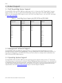
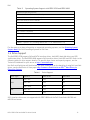
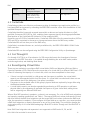
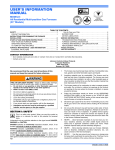
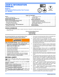
Dell PowerEdge RAID Controller Cards H700 and H800 Technical Guide Enterprise-class controllers designed for performance, reliability, and fault tolerance. Dell This document is for informational purposes only. Dell reserves the right to make changes without further notice to any products herein. The content provided is as is and without express or implied warranties of any kind. Dell, PowerEdge, PowerVault, and OpenManage are trademarks of Dell, Inc. Microsoft and Windows are either registered trademarks or trademarks of Microsoft Corporation in the United States and/or other countries. Red Hat is a registered trademark of Red Hat, Inc. in the United States and other countries. Linux is a registered trademark of Linus Torvalds. Other trademarks and trade names may be used in this document to refer to either the entities claiming the marks and names or their products. Dell disclaims proprietary interest in the marks and names of others. ©Copyright 2009–2011 Dell Inc. All rights reserved. Reproduction or translation of any part of this work beyond that permitted by U.S. copyright laws without the written permission of Dell Inc. is unlawful and strictly forbidden. Revision 3 March 2011 DELL PERC H700 and H800 Technical Guide 2 Dell Table of Contents 1 Product Comparison ........................................................................................... 5 1.1 Overview .................................................................................................. 5 1.2 PERC H700 Model Overview............................................................................. 6 1.3 PERC H800 Model Overview ............................................................................. 7 2 New Features ................................................................................................... 9 2.1 New Feature Overview .................................................................................. 9 2.2 6Gb/s SAS (SAS 2.0) Overview .......................................................................... 9 2.2.1 6Gb/s SAS Performance Benefit over 3Gb/s SAS ............................................ 10 2.2.2 6Gb/s SAS Expectation .......................................................................... 10 3 Product Support .............................................................................................. 3.1 PowerEdge™ Server Support .......................................................................... 3.2 Management Software Support....................................................................... 3.3 Operating System Support ............................................................................ 3.4 Drive Support ........................................................................................... 4 Product Overview ............................................................................................ 4.1 PERC H700 and PERC H800 Feature Overview ..................................................... 4.2 CacheCade .............................................................................................. 4.3 Cut-Through IO ......................................................................................... 4.4 Reconfiguring Virtual Disks ........................................................................... 4.5 Fault-Tolerance Features ............................................................................. 4.5.1 Non-Volatile Cache............................................................................... 11 11 11 11 12 13 13 15 15 15 16 17 4.5.2 Automatic Replace Member with Predicted Failure......................................... 17 4.5.3 Redundant Path with Load Balancing Support ............................................... 17 4.5.4 Failed Physical Disk Detection ................................................................. 17 4.5.5 Using Replace Member and Revertible Hot Spares .......................................... 17 4.5.6 Enclosure Affinity ................................................................................ 18 4.5.7 Battery Back-up of Controller Cache .......................................................... 18 4.6 Physical Disk Hot Swapping ........................................................................... 4.7 Disk Roaming............................................................................................ 4.8 Disk Migration ........................................................................................... 4.9 PERC H700 and H800 Security Key and RAID Management ....................................... 4.9.1 PERC H700 and H800 Security Key Implementation ......................................... 4.9.2 18 19 19 19 19 Configuring and Managing Secured RAID ...................................................... 19 4.10 Virtual Disk Write Cache Policies .................................................................... 4.11 Virtual Disk Read Cache Policies ..................................................................... 5 RAID Overview ................................................................................................ 5.1 About RAID .............................................................................................. 5.2 Advantages of RAID .................................................................................... 5.3 Supported RAID Levels................................................................................. 5.3.1 RAID 0 (Striped Virtual Disk without Fault Tolerance) ...................................... 20 20 21 21 21 21 21 5.3.2 RAID 1 (Mirroring) ................................................................................ 22 5.3.3 RAID 5 (Striping With Distributed Parity) ..................................................... 23 5.3.4 RAID 6 (Striping With Dual Distributed Parity) ............................................... 24 DELL PERC H700 and H800 Technical Guide 3 Dell 5.3.5 RAID 10 (Striping over Mirrored Sets) ......................................................... 25 5.3.6 RAID 50 (Striping Across RAID 5) ............................................................... 26 5.3.7 RAID 60 (Striping Across RAID 6) ............................................................... 27 Appendix A. Additional Resources.......................................................................... 29 Tables Table Table Table Table Table Table Table Table Table 1. 2. 3. 4. 5. 6. 7. 8. 9. Comparison of PERC H700 and PERC H800 to previous PERC 6/I and PERC 6/E .............. 5 6Gb/s SAS (SAS 2.0) Features ..................................................................... 10 SAS Performance Details ........................................................................... 10 PowerEdge Server Support with PERC H700 and PERC H800 .................................. 11 Operating System Support with PERC H700 and PERC H800 .................................. 12 Drive Support ........................................................................................ 12 PERC H700 and PERC H800 Features ............................................................. 13 RAID Level Migration ................................................................................ 16 Resource Contact Information and Descriptions ................................................ 29 Figures Figure Figure Figure Figure Figure Figure Figure Figure Figure Figure 1. 2. 3. 4. 5. 6. 7. 8. 9. 10. PERC H700 Integrated (Additional Sled for PCIe Slot) ........................................... 6 PERC H700 Modular ................................................................................... 7 PERC H800 Adapter ................................................................................... 8 Example of RAID 0 .................................................................................. 22 Example of RAID 1 (Mirroring) ..................................................................... 23 Example of RAID 5 (Single Virtual Disk with 5 drives).......................................... 24 Example of RAID 6 (Single Virtual Disk with 5 drives).......................................... 25 Example of RAID 10 (1 + 0) ........................................................................ 26 Example of RAID 50 (5 + 0) ........................................................................ 27 Example of RAID 60 (6 + 0) ........................................................................ 28 DELL PERC H700 and H800 Technical Guide 4 Dell 1 Product Comparison 1.1 Overview The PERC H700 (internal) and PERC H800 (external) RAID controllers mark the next stage in the evolution of the Dell™ PowerEdge™ RAID controller portfolio with the introduction of 6Gb/s SAS (SAS 2.0). PERC H700 and H800 will be supported in PowerEdge 11th Generation servers. The PERC H700 is follow-on to the PERC 6/I, and the PERC H800 is the follow-on to the PERC 6/E. Table 1. Comparison of PERC H700 and PERC H800 to previous PERC 6/I and PERC 6/E Feature/Spec NEW PERC H700 PERC 6/I NEW PERC H800 PERC 6/E Interface 6Gb (SAS 2.0) 3Gb (SAS 1.1) 6Gb (SAS 2.0) 3Gb (SAS 1.1) Bus support x8 PCIe 2.0 x8 PCIe 1.0 x8 PCIe 2.0 x8 PCIe 1.0 Ports / Channels 8 (2 x4) 8 (2 x4) 8 (2 x4) 8 (2 x4) Int/Ext Connectors 2 internal 2 internal 2 external 2 external Cache Memory 512MB BBU 512MB Non-Volatile Cache (800 MHz DDR2) 256MB (667 MHz DDR2) 512MB TBBU 512MB TNVC 1GB TNVC (800 MHz DDR2) 256MB / 512MB (667 MHz DDR2) Battery-Backed Cache Yes Yes Yes Transportable Yes Transportable RAID Levels 0, 1, 5, 6, 10, 50, 60 0, 1, 5, 6, 10, 50, 60 0, 1, 5, 6, 10, 50, 60 0, 1, 5, 6, 10, 50, 60 16 10 192 (8x MD1220) 144 (6x MD1120) HDD Support SAS and SATA SAS and SATA SAS only SAS and SATA SSD Support SAS and SATA SATA SAS only Not Supported SED Support Yes (Local Key Management) Not Supported Yes (Local Key Management) Not Supported Controller Firmware (latest rev) 7.1 6.2 7.1 6.2 Redundant Path No No Yes Yes I/O Load Balancing No No Yes Yes Cluster Support No No No No Storage Management OpenManage™ 6.2 (minimum rev) OpenManage™ 5.4 (minimum rev) OpenManage™ 6.2 (minimum rev) OpenManage™ 5.4 (minimum rev) Max physical drives in Large RAID volume (R10, R50, R60) DELL PERC H700 and H800 Technical Guide 5 Dell 1.2 PERC H700 Overview The PERC H700 internal host-RAID product offers three different models to support 11th Generation Dell PowerEdge servers: The PERC H700 Integrated card with two x4 internal mini-SAS ports supports the PCIe 2.0 x8 host interface. Cache options include standard 512 MB with battery backup unit (BBU), 512 MB non-volatile (NV) cache, or 1 GB non-volatile cache. The PERC H700 Integrated card is installed in the dedicated internal storage slot of the server. See Figure 1 for a view of the PERC H700 Integrated card. The PERC H700 Adapter with two x4 internal mini-SAS ports supports the PCIe 2.0 x8 host interface. Cache options include standard 512 MB with BBU, 512 MB non-volatile cache, or 1 GB non-volatile cache. The PERC H700 Adapter is installed in a PCIe slot in the server. See Figure 1 for a view of the PERC H700 Integrated card (adapter version is the same with the addition of a sled for adhering to the PCIe slot connection). The PERC H700 Modular card with one x4 internal SAS port and a BBU supports the PCIe 2.0 x4 host interface. The PERC H700 Modular card is installed in the integrated slot in the blade server platforms. See Figure 2 for a view of the PERC H700 Modular card. Figure 1. PERC H700 Integrated (Additional Sled for PCIe Slot) DELL PERC H700 and H800 Technical Guide 6 Dell Figure 2. PERC H700 Modular 1.3 PERC H800 Overview The PERC H800 external host-RAID product is supported with 11th Generation Dell PowerEdge servers for expanding storage to the Dell™ PowerVault™ MD1200 and MD1220 6Gb/s SAS enclosures. The PERC H800 Adapter with two x4 external mini-SAS ports supports the PCIe 2.0 x8 host interface. Cache options include the standard 512 MB transportable battery backup unit (TBBU) and the transportable 512 MB and 1 GB non-volatile cache. The PERC H800 Adapter is installed in a PCIe slot in the server. See Figure 3 for an angled view of the PERC H800 adapter. DELL PERC H700 and H800 Technical Guide 7 Dell Figure 3. DELL PERC H700 and H800 Technical Guide PERC H800 Adapter 8 Dell 2 New Features 2.1 Overview The PERC H700 and PERC H800 offer the new CacheCade feature: • Produces cost-effective performance scaling for database-type applications • Offloads Random Reads to Dell-qualified Enterprise SSD configured as CacheCade SSD • Has a standard feature of 1 GB NV cache (PERC H700/H800) The PERC H700 and PERC H800 continue to offer the following features: • 512 MB and 1 GB non-volatile cache (not supported on H700 modular) o Data retention in cache is extended from hours to years in the event of power interruption o Larger cache size of 1 GB • Cut-through IO (CTIO) o Performance boost of up to 2X IOPS performance o Optimized for superior IOPS of SSDs over HDDs o Ideal for small-block random workloads o Easy to enable • Physical disk power management o Conserve power by spinning down hot spares and unconfigured drives when not in use o Parameters are user-managed • PCI-Express Gen2.0 support • 6Gb/s SAS (SAS 2.0) host interface o Doubles the throughput performance o Support for Self Encrypting Drive (SED)—requires unique SED HDD part numbers • New LSI 2108 ROC (Raid-on-Chip) with increased I/O processor (IOP) performance • Increased internal drive support (up to 16 drives) • SAS SSD support for specific 11th Generation Dell PowerEdge servers • RAID volumes can be migrated from PERC 6/I, PERC 6/E, SAS 6/IR and PERC H200 controllers. Backwards migration is not supported. • Change in Virtual Disk default read cache policy (The default VD read cache policy has been changed to Adaptive Read Ahead from No Read Ahead.) • Display of expected and negotiated link rate for drives The PERC H800 also offers the following features for PowerVault MD1200 and MD1220 enclosures: • • • • Increased capacity and scalability—up to 192 drives on one host-RAID controller Increased flexibility o Mix of 2.5” (MD1220) and 3.5” (MD1200) enclosures behind a PERC H800 o Mix of 2.5” and 3.5” drives in the MD1200 SAS SSD support for Dell PowerVault MD1200 and MD1220 enclosures 22-drive RAID-10 can be configured with PERC H800 in the CTRL-R BIOS utility 2.2 6Gb/s SAS (SAS 2.0) Overview The 6Gb/s SAS 2.0 specification doubles the current 3Gb/s SAS data transfer rate. 6Gb/s SAS is designed for backward compatibility with 3Gb/s SAS and 3Gb/s SATA hard drives. Regardless of the drive speed, 6Gb/s controllers will deliver significant performance improvements in both read and write applications as compared to their 3Gb/s predecessors. DELL PERC H700 and H800 Technical Guide 9 Dell Other new features of the 6Gb/s SAS controllers will offer improved signal integrity and additional safeguards to enhance data protection with support for SED (Self-Encrypting Drive) technology. Table 2. 6Gb/s SAS (SAS 2.0) Features DAS-based Server Storage 2.2.1 6Gb/s Throughput 3Gb/s Compatible Standard Mini-SAS Connectors (SFF-8087 and SFF-8088) DFE (Decision Feedback Equalization) improved signaling SSC (Spread Spectrum Clocking) reduced radiated emissions Enhanced Security with SED (SelfEncrypting Drive) support Improved Scalability 6Gb/s SAS Performance Benefit over 3Gb/s SAS In small disk drive configurations (one to eight drives) the aggregate media rate of the disks (the speed at which the disk heads can read and write data) become the bottleneck for storage throughput. As business storage needs grow, IT centers can add more disk drives to their storage infrastructure, and the latest generation of SAS allows server performance to scale past the 3Gb/s SAS performance limitations: from 2.4 GB/s to 4.8 GB/s unidirectional. Table 3. SAS Performance Details SAS Generation PCI-Express Interface Approximate number of SAS HDDs required saturate bandwidth (RAID 0) 1.0 (3Gb) 1.0 8 to10 2.0 (6Gb) 2.0 16 to 20 In addition to the improvements in the SAS bandwidth, PCI Express 2.0 provides double the systemto-storage controller interconnect speed. The x8 PCI Express 1.0 interface linking the controller to the host platform limited throughput even further to a theoretical 2GB/s maximum, that limitation has been raised to 4GB/s (unidirectional). 2.2.2 6Gb/s SAS Expectation RAID controllers employing 6Gb/s SAS technology excel in both high IOP and high bandwidth applications. Applications and environments that benefit most range from traditional data center applications (such as random IOPs intensive email, web and database servers) to streaming and archival applications that will benefit from improved sequential read and write throughput. This means more users, more video streams, more email accounts, and faster backups are now possible. DELL PERC H700 and H800 Technical Guide 10 Dell 3 Product Support 3.1 Dell PowerEdge Server Support The Dell PERC H700 and PERC H800 are supported with 11th Generation Dell™ PowerEdge™ servers. Refer to Table 1 for the 11th Generation PowerEdge servers that support the PERC H700 and PERC H800. For the latest Dell PERC support matrix with Dell PowerEdge servers, visit the PERC web page at www.dell.com/PERC. Table 4. PowerEdge Server Support with PERC H700 and PERC H800 PERC H700 Internal Integrated PERC H700 Internal Adapter PERC H700 Internal Modular PERC H800 External Adapter R510 R610 T610 R710 T710 R715 R810 R815 R910 R310 T310 R410 T410 M610 M610x M710 M910 T310 R310 R410 T410 R510 R610 T610 M610x R710 T710 R715 R810 R815 R910 3.2 Management Software Support The Dell PERC H700 and H800 are supported with 11th Generation Dell PowerEdge servers and managed through common Dell OpenManage™ Storage Management software (minimum version 6.2). For pre-OS configuration, the PERC BIOS utility can also be used to configure and troubleshoot the PERC H700 and PERC H800 products. 3.3 Operating System Support The Dell PERC H700 and PERC H800 provide operating system support based on Dell 11th Generation PowerEdge support requirements as shown in Error! Reference source not found.. For the latest list of supported operating systems and driver installation instructions, see the system documentation on the Dell Support website at support.dell.com/manuals. For specific operating system service pack requirements, see the Drivers & Downloads page on the Dell Support website. DELL PERC H700 and H800 Technical Guide 11 Dell Table 5. Operating System Support with PERC H700 and PERC H800 Supported Operating Systems Microsoft® Windows Server® 2003 Family Microsoft Windows Server 2008 Family Microsoft Windows Server 2008 R2 Red Hat® Enterprise Linux® Version 4 and Version 5 RHEL 4.7 and later (32 and 64 bit) RHEL 5.3 and later (32 and 64 bit) Sun® Solaris™ 10 (64-bit) Novell® SUSE® Linux® Enterprise Server Version 10 (64-bit) and Version 11 (64-bit) SLES10 SP2 and later SLES11 GM and later VMware® vSphere™ 4.1 (including VMware ESX® 4.1 or VMware ESXi™ 4.1) For the most up-to-date information on supported operating systems, see the Operating System Support Matrix for Dell PowerEdge Systems on Dell.com. 3.4 Drive Support The Dell PERC H700 supports SAS and SATA interface drives, both HDD (hard-disk drive) and SSD (solid-state drive). The Dell PERC H800 supports SAS interface drives, both HDD and SSD. Refer to the following table for drive support details. For specific form-factor and capacity support, see the Technical Guidebook for your server at http://www.dell.com. Non Dell certified drives will be blocked. For more information on the benefits of using Dell certified drives, see the Dell Point of View paper Why Customers Should Insist on DELLTM Hard Drives for Enterprise Systems. Table 6. Drive Type HDD SSD Drive Support Interface PERC H700 PERC H800 6Gb/s SAS Yes Yes 3Gb/s SAS Yes Yes 3Gb/s SATA Yes No 3Gb/s SAS Yes Yes 3Gb/s SATA Yes No SATA interface drives are not supported with PERC H800 and the Dell PowerVault MD1200 and MD1220 enclosures. DELL PERC H700 and H800 Technical Guide 12 Dell 4 Product Overview 4.1 PERC H700 and PERC H800 Overview Table 7. PERC H700 and PERC H800 Features Feature PERC H700 Integrated/Adapter PERC H700 Modular PERC H800 Adapter RAID Levels 0, 1, 5, 6, 10, 50, 60 0, 1, 5, 6, 10 0, 1, 5, 6, 10, 50, 60 Ports 2 x4 internal mini-SAS wide ports 1 x4 integrated SAS wide port 2 x4 external mini-SAS wide ports Processor Dell adapter SAS RAID-onChip, 8-port with LSI 2108 chipset Dell adapter SAS RAID-onChip, 4 lanes with LSI 2108 chipset Dell adapter SAS RAID-onChip, 8-port with LSI 2108 chipset Hardware Exclusive OR (XOR) Assistance Yes Yes Yes Battery Backup (BBU) Yes Yes Yes, transportable Cache Memory 512MB BBU 512MB NVC 1GB NVC integrated DDR2 512MB integrated DDR2 512MB TBBU 512MB TNVC 1GB TNVC DDR2 Cache Function Write-Back, Write-Through, Adaptive Read Ahead, No-Read Ahead, Read Ahead Maximum number of drives per large RAID volume (R10, R50, R60) 16 drives 4 drives 192 drives (8 – MD1220) Maximum number of virtual disks (RAID volumes) per disk group 16 16 16 Multiple Virtual Disks (RAID volumes) per controller Up to 64 Up to 64 Up to 64 PCI-Express 2.0 Support x8 x4 x8 Cut-through IO Yes Yes Yes DELL PERC H700 and H800 Technical Guide 13 Dell Feature PERC H700 Integrated/Adapter PERC H700 Modular PERC H800 Adapter Physical Disk Power Management Yes Yes Yes RAID Level Migration Yes Yes Yes On-line Capacity Expansion Yes Yes Yes Non-Volatile Cache Yes No Yes SMART Support Yes Yes Yes Redundant Path Support N/A N/A Yes Dedicated and Global Hot Spares Yes Yes Yes Revertible Hot Spares Yes Yes Yes Hot Swap Devices Yes Yes Yes Disk Roaming Yes Yes Yes Disk Migration Yes Yes Yes SED Support Yes Yes Yes Mixed Capacity Physical Drive Yes Yes Yes Enclosures per Port N/A N/A Up to 4 per port (total of 8 enclosures per Adapter) Enclosure Hot-Add N/A N/A Yes SAS port connection LED LEDs used to determine the status of the SAS port Supported. Port State; LED State Power On State; Off Reset State; Off All links in port Connected; Green On 1 or more links not connected (only applicable in wide port configurations); Amber On All links in port disconnected or Cable disconnected; Off DELL PERC H700 and H800 Technical Guide 14 Dell Feature PERC H700 Integrated/Adapter Clustering Card and software stack enables High Availability Clusters PERC H700 Modular PERC H800 Adapter Not supported 4.2 CacheCade CacheCade provides cost-effective performance scaling for database-type application profiles in a host-based RAID environment by extending the PERC RAID controller cache with the addition of Dellqualified Enterprise SSDs. CacheCade identifies frequently-accessed areas within a data set and copies this data to a Dellqualified, Enterprise SSD (SATA or SAS), enabling faster response time by directing popular Random Read queries to the CacheCade SSD instead of to the underlying HDD. Supporting up to 512 GB of extended cache, CacheCade SSDs must all be the same interface (SATA or SAS) and will be contained in the server or storage enclosure where the RAID array resides. CacheCade SSDs will not be a part of the RAID array. CacheCade is a standard feature on, and only available with, the PERC H700/H800 1 GB NV Cache RAID controller. CacheCade SSDs can be configured using the PERC BIOS Configuration Utility or OpenManage. 4.3 Cut-Through IO Cut-through IO (CTIO) is an IO accelerator for SSD arrays that boosts the throughput of devices connected to the PERC Controller. It is enabled through disabling the write-back cache (enable write-through cache) and disabling Read Ahead. 4.4 Reconfiguring Virtual Disks There are two methods to reconfigure RAID virtual disks—RAID Level Migration (RLM) and Online Capacity Expansion (OCE). RLM involves the conversion of a virtual disk to a different RAID level. OCE refers to increasing the capacity of a virtual disk, which can be accomplished in three ways: If there is a single virtual disk in a disk group and free space is available, the virtual disk’s capacity can be expanded within that free space. If a virtual disk is created and it does not use the maximum size of the disk group, free space is available. Free space is also available when a disk group’s physical disks are replaced by larger disks using the Replace Member feature. A virtual disk's capacity can also be expanded by performing an OCE operation to add more physical disks by encompassing all available free space on a given virtual disk, adding drives and/or migrating to a different RAID level. When a RLM/OCE operation is complete, a reboot is not necessary. For a list of RAID level migrations and capacity expansion possibilities, see Table 1. The source RAID level column indicates the virtual disk level before the RAID level migration and the target RAID level column indicates the RAID level after the operation is complete. If you configure 64 virtual disks on a controller, you cannot perform a RAID level migration or capacity expansion on any of the virtual disks. The controller changes the write cache policy of all virtual disks undergoing a RLM/OCE to Write-Through until the RLM/OCE is complete. Note: RAID level migration and expansion is not supported on RAID levels 10, 50, and 60. DELL PERC H700 and H800 Technical Guide 15 Dell Table 8. RAID Level Migration Source RAID Level Target RAID Level # of Physical Drives (Beginning) # of Physical Drives (End) Capacity Expansion Possible Description RAID 0 RAID 1 1 2 No Converting nonredundant virtual disk into a mirrored virtual disk by adding one drive. RAID 0 RAID 5 1 or more 3 or more Yes At least one drive needs to be added for distributed parity data. 4 or more Yes At least two drives need to be added for dual distributed parity data. RAID 0 RAID 6 1 or more RAID 1 RAID 0 2 2 or more Yes Removes redundancy while increasing capacity. RAID 1 RAID 5 2 3 or more Yes Maintains redundancy while doubling capacity. RAID 1 RAID 6 2 4 or more Yes Two drives are required to be added for distributed parity data. RAID 5 RAID 0 3 or more 3 or more Yes Converting to a nonredundant virtual disk and reclaiming disk space used for distributed parity data. RAID 5 RAID 6 3 or more 4 or more Yes At least one drive needs to be added for dual distributed parity data. RAID 6 RAID 0 4 or more 4 or more Yes Converting to a nonredundant virtual disk and reclaiming disk space used for distributed parity data. RAID 6 RAID 5 4 or more 4 or more Yes Removing one set of parity data and reclaiming disk space used for it. 4.5 Fault-Tolerance Features Below is a list of features that provide fault tolerance to prevent data loss: Non-volatile cache: extends data retention from hours to years Support for SMART Redundant path support (for PERC H800 only) Physical disk failure detection DELL PERC H700 and H800 Technical Guide 16 Dell 4.5.1 Physical disk rebuild using hot spares Enclosure affinity Parity generation and checking (for RAID 5, 50, 6, and 60 only) Battery backup of controller cache to protect data Detection of batteries with low charge after boot up Non-Volatile Cache Dell PERC controllers with non-volatile (NV) cache use the standard battery as contained in the Dell PERC controllers with a battery back-up unit (BBU). The difference is in battery implementation: 4.5.2 The battery in the BBU offering retains the data in cache in the event of a power cycle for a guaranteed period of 24 hours (typically up to 72 hours). The battery in the NV cache offering will transfer the data from cache to flash in the event of a power cycle, where the data will be retained for up to ten years. Automatic Replace Member with Predicted Failure A Replace Member operation can occur when there is a SMART predictive failure reporting on a drive in a virtual disk. The automatic Replace Member is initiated when the first SMART error occurs on a physical disk that is part of a virtual disk. The target drive needs to be a hot spare that qualifies as a rebuild drive. The physical disk with the SMART error is marked as failed only after the successful completion of the Replace Member. This avoids putting the array in degraded status. If an automatic Replace Member occurs using a source drive that was originally a hot spare (that was used in a rebuild), and a new drive added for the Replace Member operation as the target drive, the hot spare reverts to the hot spare state after a successful Replace Member operation. To enable the automatic Replace Member, use the Dell OpenManage storage management application. 4.5.3 Redundant Path with Load Balancing Support The PERC H800 adapter can detect and use redundant paths to drives contained in enclosures. This provides the ability to connect two SAS cables between a controller and an enclosure for path redundancy. The controller is able to tolerate the failure of a cable or Enclosure Management Module (EMM) by using the remaining path. When redundant paths exist, the controller automatically balances I/O load through both paths to each disk drive. This load balancing feature increases throughput to each drive and is automatically turned on when redundant paths are detected. To set up your hardware to support redundant paths, see the Setting up Redundant Path Support on the PERC H800 Adapter section in the PERC H700 and PERC H800 User’s Guide (support.dell.com/manuals). 4.5.4 Failed Physical Disk Detection The controller automatically detects and rebuilds failed physical disks when you place a new drive in the slot where the failed drive resided or when an applicable hot spare is present. Automatic rebuilds can be performed transparently with hot spares. If you have configured hot spares, the controllers automatically try to use them to rebuild failed physical disks. 4.5.5 Using Replace Member and Revertible Hot Spares The Replace Member functionality allows a previously commissioned hot spare to be reverted back to a usable hot spare. When a drive failure occurs within a virtual disk, an assigned hot spare (dedicated or global) is commissioned and begins rebuilding until the virtual disk is optimal. After the failed drive is replaced (in the same slot) and the rebuild to the hot spare is complete, the controller automatically starts to copy data from the commissioned hot spare to the newly inserted drive. After the data is copied, the new drive is part of the virtual disk and the hot spare is reverted back to DELL PERC H700 and H800 Technical Guide 17 Dell being a ready hot spare. This allows hot spares to remain in specific enclosure slots. While the controller is reverting the hot spare, the virtual disk remains optimal. The controller automatically reverts a hot spare only if the failed drive is replaced with a new drive in the same slot. If the new drive is not placed in the same slot, a manual Replace Member operation can be used to revert a previously commissioned hot spare. 4.5.6 Enclosure Affinity Enclosure affinity is used to set the preference for a hot spare to be used to rebuild a physical disk that resides in the same physical enclosure. This does not preclude the hot spare from being provisioned to a second enclosure if there are no other hot spares present. For example, if there are two enclosures and each enclosure has a hot spare with affinity set, then upon a drive failure the hot spare will be provisioned from the same enclosure as the failed drive. Hot-spare enclosure affinity can be configured only if you are using an external storage enclosure. 4.5.7 4.5.7.1 Battery Back-up of Controller Cache Battery Management The transportable battery backup unit (TBBU) is a cache memory module with an integrated battery pack that enables you to transport the cache module with the battery in a new controller. The TBBU protects the integrity of the cached data on the PERC H800 adapter by providing backup power during a power outage. The battery backup unit (BBU) is a battery pack that protects the integrity of the cached data on the PERC H700 cards by providing backup power during a power outage. The battery provides up to 24 hours of backup power for the cache memory. 4.5.7.2 Battery Learn Cycle Learn cycle is a battery calibration operation performed by the controller periodically to determine the condition of the battery. This operation cannot be disabled. The time frame for completion of a learn cycle is a function of the battery charge capacity and the discharge/charge currents used. For PERC H700 or H800 cards, the expected time frame for completion of a learn cycle is approximately seven hours and consists of the following parts: • Learn cycle discharge cycle: approximately three hours • Learn cycle charge cycle: approximately four hours During the discharge phase of a learn cycle, the PERC H700 or H800 battery charger is disabled and remains disabled until the battery is discharged. After the battery is discharged, the charger is reenabled. 4.6 Physical Disk Hot Swapping Hot swapping is the manual replacement of a unit in a disk subsystem while the subsystem is performing its normal functions. The following requirements must be met before hot swapping a physical disk: • The system backplane or enclosure must support hot swapping. • The replacement drive must be of the same protocol and drive technology. For example, only a SAS HDD can replace a SAS HDD; only a SATA SSD can replace a SATA SSD. • The replacement drive must be of equal or greater capacity than the one it is replacing. DELL PERC H700 and H800 Technical Guide 18 Dell 4.7 Disk Roaming The PERC H700 and H800 cards support moving physical disks from one cable connection or backplane slot to another on the same controller. The controller automatically recognizes the relocated physical disks and logically places them in the proper virtual disks that are part of the disk group. Disk roaming can be performed only when the system is turned off. Disk roaming should not be performed during RAID level migration (RLM) or online capacity expansion (OCE). This causes loss of the virtual disk. 4.8 Disk Migration The PERC H700 and H800 cards support migration of virtual disks from one controller to another without taking the target controller offline. However, the source controller must be offline prior to performing the disk migration. The controller can import RAID virtual disks in optimal, degraded, or partially degraded states. A virtual disk cannot be imported if it is in an offline state. Disks cannot be migrated back to previous PERC RAID controllers. When a controller detects a physical disk with an existing configuration, it flags the physical disk as foreign, and it generates an alert indicating that a foreign disk was detected. Disk roaming should not be used during RLM or online capacity expansion OCE as it can cause loss of the virtual disk. Virtual disks that are created on the PERC 6 and H200 family of controllers can be migrated to the PERC H700 and H800 controllers without risking data or configuration loss. Migrating virtual disks from the PERC H700 and H800 cards to PERC 6 or PERC H200 is not supported. During the discharge phase of a learn cycle, the PERC H700 or H800 battery charger is disabled and remains disabled until the battery is discharged. After the battery is discharged, the charger is reenabled. 4.9 PERC H700 and H800 Security Key and RAID Management 4.9.1 PERC H700 and H800 Security Key Implementation The Dell PowerEdge RAID Controller (PERC) H700 and H800 cards support encryption of data on the drives when using Dell qualified self-encrypting drives (SEDs). This feature provides protection to the data at rest in the event of theft or loss of drives. There is one security key per controller which resides in the controller memory and it can be managed by the user (local key management). The security key is used by the controller to lock and unlock access to encryption-capable physical drives. In order to take advantage of this feature, you need to create a security key on your PERC H700 or PERC H800 controller and have Dell qualified SEDs. 4.9.2 Configuring and Managing Secured RAID Dell OpenManage storage management applications enable you to create and manage a security key, manage and configure the RAID system, create and manage multiple disk groups, control and monitor multiple RAID systems, and provide online maintenance. The management applications for PERC H700 and H800 include: • • Dell OpenManage Storage Management BIOS Configuration Utility DELL PERC H700 and H800 Technical Guide 19 Dell 4.10 Virtual Disk Write Cache Policies The write cache policy of a virtual disk determines how the controller handles writes to that virtual disk. Write-Back and Write-Through are the two write cache policies and can be set on virtual disks individually. All RAID volumes will be presented as Write-Through (WT) to the operating system (Windows and Linux) independent of the actual write cache policy of the virtual disk. The PERC cards manage the data in cache independently of the operating system or any applications. You can use OpenManage or the BIOS configuration utility to view and manage virtual disk cache settings. In Write-Through caching, the controller sends a data-transfer completion signal to the host system when the disk subsystem has received all the data in a transaction. In Write-Back caching, the controller sends a data transfer completion signal to the host when the controller cache has received all the data in a transaction. The controller then writes the cached data to the storage device in the background. The risk of using Write-Back cache is that the cached data can be lost if there is a power failure before it is written to the storage device. This risk is mitigated by using a BBU on PERC H700 or H800 cards. Write-Back caching has a performance advantage over Write-Through caching. The default cache setting for virtual disks is Write-Back caching. Certain data patterns and configurations perform better with a Write-Through cache policy. Write-Back caching is used under all conditions in which the battery is present and in good condition. Write-Through caching is used under all conditions in which the battery is missing or in a low-charge state. Low-charge state is when the battery is not capable of maintaining data for at least 24 hours in the case of a power loss. Write-Back mode is available when the user selects Force WB with no battery. When Forced WriteBack mode is selected, the virtual disk is in Write-Back mode even if the battery is not present. It is recommended that you use power backup system when forcing Write-Back to ensure there is no loss of data if the system suddenly loses power. 4.11 Virtual Disk Read Cache Policies The read policy of a virtual disk determines how the controller handles reads to that virtual disk. The read policies are: • Always Read Ahead—Read-Ahead capability allows the controller to read sequentially ahead of requested data and to store the additional data in cache memory, anticipating that the data is required soon. This speeds up reads for sequential data, but there is little improvement when accessing random data. • No Read Ahead—Disables the Read-Ahead capability. • Adaptive Read Ahead—When selected, the controller begins using Read-Ahead if the two most recent disk accesses occurred in sequential sectors. If the read requests are random, the controller reverts to No Read Ahead mode. Note: The default read cache setting for virtual disks is Adaptive Read Ahead. DELL PERC H700 and H800 Technical Guide 20 Dell 5 RAID Overview 5.1 About RAID RAID is a way of storing data on multiple independent physical disks for the purpose of enhanced performance and/or fault tolerance. The physical disks combine to make up what is called a virtual disk. This virtual disk appears to the host system as a single logical unit or drive. For example, if you have physical disk 1 and physical disk 2 forming a RAID virtual disk, those two disks appear to the host system as one disk. Virtual Disks are sometimes called volumes, containers, or arrays. There are several different RAID types or levels, which determine how the data is placed in the virtual disk. Each RAID level has specific data protection and system performance characteristics. The following are commonly used RAID levels: • • • RAID 0: Striping without parity, improved performance, additional storage, no fault tolerance RAID 1: Mirroring without parity, fault tolerance for disk errors, and single disk failures RAID 5: Striping with distributed parity, improved performance, fault tolerance for disk errors, and single disk failures • RAID 6: Striping with dual parity, fault tolerance for dual drive failures • RAID 10: Mirroring combined with striping, better performance, fault tolerance for disk errors, and multiple drive failure (one drive failure per mirror set) • RAID 50: Combines multiple RAID 5 sets with striping, improved performance, fault disk errors, and multiple drive failures (one drive failure per span) • RAID 60: Combines multiple RAID 6 sets with striping, improved performance, fault disk errors, and multiple drive failures (two drive failures per span) These RAID levels are discussed in more detail later in this document. You can manage RAID virtual disks with a RAID controller (hardware RAID) or with software (software RAID). 5.2 Advantages of RAID Depending on how you implement RAID, the benefits include one or both of the following: • • Faster performance—In RAID 0, 10, 50, or 60 virtual disks, the host system can access simultaneously. This improves performance because each disk in a virtual disk has to handle the request. For example, in a two-disk virtual disk, each disk needs to provide only its requested data. Data protection—In RAID 1, 10, 5, 6, 50, and 60 virtual disks, the data is backed up on disk (mirror). In the RAID 5, 50, 6, or 60 virtual disks, the data is also parity protected. RAID 10, 50, and 60 also allow the host to access disks simultaneously. 5.3 Supported RAID Levels Dell servers that use RAID controllers may support RAID 0, 1, 5, 6, 10, 50, and 60 depending upon the controller. The following is a brief explanation of these levels. 5.3.1 RAID 0 (Striped Virtual Disk without Fault Tolerance) RAID 0, also known as striping, maps data across the physical drives to create a large virtual disk. The data is divided into consecutive segments or stripes that are written sequentially across the drives in the virtual disk. See Figure 4. Each stripe has a defined size or depth in blocks. DELL PERC H700 and H800 Technical Guide 21 Dell For example, a four-drive virtual disk may be configured with 16 stripes (four stripes of designated space per drive). Stripes A, B, C and D are located on corresponding hard drives 0, 1, 2, and 3. Stripe E, however, appears on a segment of drive 0 in a different location than stripe A; stripes F through H appear accordingly on drives 1, 2 and 3. The remaining eight stripes are allocated in the same even fashion across the drives. RAID 0 provides improved performance because each drive in the virtual disk needs to handle only part of a read or write request. However, because none of the data is mirrored or backed up on parity drives, one drive failure makes the virtual disk inaccessible and the data is lost permanently. Data 1 Data 5 Data 9 Data 13 Drive 0 Data 2 Data 6 Data 10 Data 14 Drive 1 Figure 4. Data 3 Data 7 Data 11 Data 15 Drive 2 Data 4 Data 8 Data 12 Data 16 Drive 3 Example of RAID 0 Advantages of RAID 0 I/O performance is greatly improved by spreading the I/O load across many channels and drives (best performance is achieved when data is striped across multiple channels with only one drive per channel) No parity calculation overhead is involved Very simple design Easy to implement Disadvantages of RAID 0 5.3.2 Not a "true" RAID because the failure of just one drive will result in all data in a virtual disk being lost Should not be used for critical data unless another form of data redundancy is deployed RAID 1 (Mirroring) RAID 1 is achieved through disk mirroring to ensure data reliability or a high degree of fault tolerance. In a RAID 1 configuration, the RAID management software instructs the subsystem's controller to store data redundantly across a number of the drives (mirrored set) in the virtual disk. See Figure 5. In other words, if a disk fails, the mirrored drive takes over and functions as the primary drive. DELL PERC H700 and H800 Technical Guide 22 Dell Data 1 Data 2 = Data 3 Data 4 Drive 0 Figure 5. Data 1 Data 2 Data 3 Data 4 Drive 1 Example of RAID 1 (Mirroring) Advantages of RAID 1 High performance up to twice the read transaction rate of single disks, and the same write transaction rate as single disks 100 percent redundancy of data means no rebuild of data is necessary in case of disk failure, just a copy to the replacement disk Typically supports hot-swap disks Simplest RAID storage subsystem design Fastest recovery of data after a drive failure, no data has to be recreated from parity codes on retrieval Disadvantages of RAID 1 5.3.3 Highest disk overhead of all RAID types (100 percent) results in inefficient use of drive capacity Limited capacity since the virtual disk can only include two disk drives RAID 5 (Striping With Distributed Parity) RAID 5 maps the data across the drives and stores parity information for each data stripe on different drives in the virtual disk. Data redundancy is maintained with a technique called parity checking. With this technique, the RAID controller writes information called parity bits on the disks. Parity data is distributed across disks in the RAID 5 virtual disk such that any 1 disk failure within the virtual disk allows data to be recreated from the remaining disks. Parity is used to maintain data integrity and to rebuild lost data in case of drive failures. Parity bit data can be written on a single drive (this is RAID Level 3), but during periods of high write activity, the parity disk can become saturated with writes. This reduces the server’s write throughput. However, RAID Level 5 reduces parity write bottlenecks by allowing all of the drives in the virtual disk to assume part of the parity responsibilities. This alleviates the single drive bottleneck, improving overall subsystem throughput. Figure 6 shows how the parity data is distributed among five hard drives. A RAID 5 virtual disk can preserve data if one drive fails. However, if two drives fail, the virtual disk will fail. DELL PERC H700 and H800 Technical Guide 23 Dell Parity Data 1 Data 2 Data 3 Data 4 0 parity Generation Data 5 Data 6 Data 7 1 parity Data 8 Data 9 Data 10 2 parity Data 11 Data 12 Data 13 3 parity Data 14 Data 15 Data 16 Data 17 Data 18 Data 19 Data 20 Drive 3 Drive 4 Drive 5 4 parity Drive 1 Figure 6. Drive 2 Example of RAID 5 (Single Virtual Disk with 5 drives) Advantages of RAID 5 Most efficient use of drive capacity of all the redundant RAID configurations High read transaction rate Medium-to-high write transaction rate Disadvantages of RAID 5 5.3.4 Disk failure has a medium impact on throughput Most complex controller design Retrieval of parity information after a drive failure takes longer than with mirroring RAID 6 (Striping With Dual Distributed Parity) RAID 6 provides data redundancy by using data striping in combination with parity information. See Figure 7. Similar to RAID 5, the parity is distributed within each stripe. RAID 6, however, uses an additional physical disk to maintain parity, such that each stripe in the disk group maintains two disk blocks with parity information. The additional parity provides data protection in the event of two disk failures. Figure 7 depicts the RAID 6 data layout. The second set of parity drives are denoted by Q. The P drives follow the RAID 5 parity scheme. The parity blocks on Q drives are computed using Galois Field mathematics. There is no performance hit on read operations. However, as a second independent parity data needs to be generated for each write operation, there is a performance hit during write. Due to dual data protection, a RAID 6 VD can survive the loss of two drives or the loss of a drive when one of its drives is being rebuilt. DELL PERC H700 and H800 Technical Guide 24 Dell Parity Data 1 Data 2 Data 3 P parity Q parity Generation Data 5 Data 6 P parity Q parity Data 8 Data 9 P parity Q parity Data 11 Data 12 P parity Q parity Data 14 Data 15 Data 16 Q parity Data 17 Data 18 Data 19 P parity Drive 3 Drive 4 Drive 5 Drive 1 Figure 7. Drive 2 Example of RAID 6 (Single Virtual Disk with 5 drives) Advantages of RAID 6 Can survive the loss of two disks without losing data Data redundancy, high read rates, and good performance Disadvantages of RAID 6 5.3.5 Requires two sets of parity data for each write operation, resulting in significant decrease in write performance Additional costs because of the extra capacity required by using two parity blocks per stripe Retrieval of parity information after a drive failure takes longer than with mirroring RAID 10 (Striping over Mirrored Sets) RAID 10 combines striping and mirroring to produce large virtual disks with high performance and fault-tolerance. The performance gain comes from striping across mirror sets without the need for parity calculations. See Figure 8. Although this delivers the highest performance, the drive storage overhead is 100 percent because the entire virtual disk is mirrored. This is an excellent solution for sites that require the highest level of performance and redundancy, as well as the fastest recovery of data after a drive failure. DELL PERC H700 and H800 Technical Guide 25 Dell RAID 0 RAID 1 RAID 1 Data 1 Data 3 Data 5 = Data 7 Drive 0 Data 1 Data 2 Data 3 Data 4 Data 5 Data 6 Data 7 Data 8 Drive 1 Figure 8. Data 2 = Drive 2 Data 4 Data 6 Data 8 Drive 3 Example of RAID 10 (1 + 0) Advantages of RAID 10 RAID 10 has the same redundancy as RAID level 1 High I/O rates are achieved by striping RAID 1 segments Allows creation of largest RAID group with up to 192 drives connected to PERC H800 Disadvantages of RAID 10 5.3.6 Most expensive RAID solution Requires 2n where n > 1 disks RAID 50 (Striping Across RAID 5) RAID 50 is a variation of RAID 5 that maps data across two or more RAID 5 virtual disks. The RAID 5 subset must have at least three disks. Figure 9 illustrates how the parity data is stored. RAID 50 stripes data across each RAID 5 subset. RAID 50 provides a higher degree of fault tolerance since 1 drive per RAID 5 set may fail without data being lost. A performance increase over RAID 5 may be realized depending on the configuration due to fewer disks reads per parity calculation. For example, if a comparison of a RAID 5 virtual disk with 6 disks were made to a RAID 50 virtual disk with two 3 disk RAID 5 virtual disks, the parity calculation on the RAID 10 virtual disk would require reading all 6 disks each time, where the parity calculation on the RAID 50 may require only reading 3. This may vary depending on several factors such as cache and data block sizes. DELL PERC H700 and H800 Technical Guide 26 Dell RAID 0 RAID 5 RAID 5 Parity Generation 0 parity Data 1 Data 2 Data 5 1 parity Data 6 2 parity Data9 Data 10 Drive 1 Drive 2 Figure 9. Drive 3 Data 3 Data 4 0 parity Data 7 1 parity Data 8 Data 11 Data 12 Drive 5 Drive 6 2 parity Drive 4 Parity Generation Example of RAID 50 (5 + 0) Advantages of RAID 50 Allows creation of largest RAID groups, up to 256 drives (theoretical; large RAID volumes are allowed for up to 192 drives connected to PERC H800) High read transaction rate Higher degree of fault tolerance due to parity calculation being done for each RAID 5 subset Potential for faster read transaction rates over large RAID 5 virtual disks Medium-to-high write transaction rate Disadvantages of RAID 50 5.3.7 Disk failure has a medium impact on throughput One of the more complex RAID implementations Less space efficient than RAID 5 since separate parity calculations are done for each RAID 5 subset Retrieval of parity information after a drive failure takes longer than using a mirrored solution RAID 60 (Striping Across RAID 6) RAID 60 is striping over more than one span of physical disks that are configured as a RAID 6. The RAID 6 subset must have at least four disks. For example, a RAID 6 disk group that is implemented with four physical disks and then continues on with a disk group of four more physical disks would be a RAID 60. See Figure 10. RAID 60 stripes data across each RAID 6 subset. RAID 60 provides a higher degree of fault tolerance since 2 drives per RAID 6 set may fail without data being lost. A performance increase over RAID 6 may be realized depending on the configuration due to fewer disks reads per parity calculation. For example, if a comparison of a RAID 6 virtual disk with 8 disks were made to a RAID 60 virtual disk with two 4 disk RAID 6 virtual disks, the parity calculation on the RAID 10 virtual disk would require reading all 6 disks each time, where the parity calculation on the RAID 60 may require only reading 4. This may vary depending on several factors such as cache and data block sizes. DELL PERC H700 and H800 Technical Guide 27 Dell RAID 0 RAID 6 RAID 6 Parity Generation Data 1 Data 2 P parity Q parity Data 3 Data 4 P parity Q parity Data 5 P parity Q parity Data 6 Data 7 P parity Q parity Data 8 P parity Q parity P parity Q parity Data 11 Data 12 Q parity Data 9 Data 14 Data 10 Data 13 P parity Q parity Data 15 Data 16 P parity Drive 3 Drive 4 Drive 5 Drive 6 Drive 7 Drive 8 Drive 1 Drive 2 Parity Generation Figure 10. Example of RAID 60 (6 + 0) Advantages of RAID 60 Allows creation of largest RAID groups, up to 256 drives (theoretical); large RAID volumes are allowed for up to 192 drives connected to PERC H800 High degree of fault tolerance due to 2 parity calculations being done for each RAID 6 subset Medium-to-high write transaction rate Disadvantages of RAID 60 One of the more complex RAID implementations Less space-efficient than RAID 6 since separate parity calculations are done for each RAID 6 subset Retrieval of parity information after a drive failure takes longer than using a mirrored solution DELL PERC H700 and H800 Technical Guide 28 Dell Appendix A. Additional Resources Table 9. Resource Contact Information and Descriptions Type Of Information URL Description PERC Resources http://www.dell.com/PERC Support matrix, whitepapers, and important links PERC Hardware Owner’s Manual http://support.dell.com/manuals Specifications, feature overview and descriptions, installation, management, and troubleshooting OpenManage User Documentation http://www.support.dell.com/ manuals User Guide for OMSS questions and support Break/Fix First contact for product issues. www.support.dell.com (Customer tab) Troubleshooting issues DELL PERC H700 and H800 Technical Guide 29