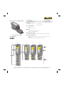
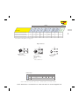
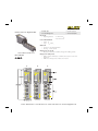
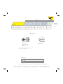
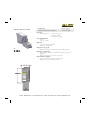
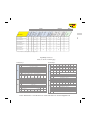
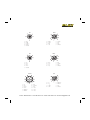
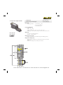
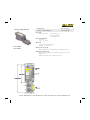
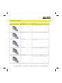
1
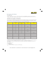
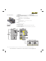
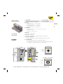
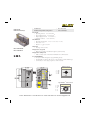
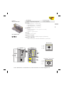
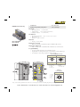
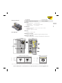
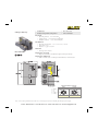
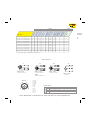
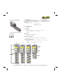
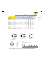
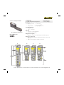
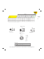
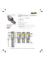
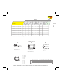
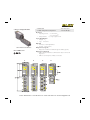
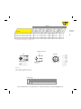
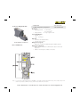
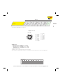
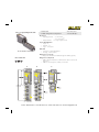
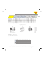
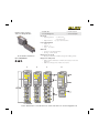
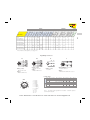
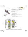
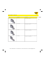
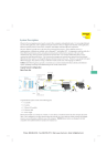
The BL67 Solution
BL67 combines all the flexibility of an in-the-cabinet PLC I/O system with modularity, ruggedness and
connectorization. BL67 complements the AIM™, BL20 and piconet ® product families to meet the needs of unique
applications, such as small machine or conveyor systems requiring IP 67 protection.
The BL67 modular concept is a very flexible approach to connectorized I/O. The gateway, base and electronic
modules provide many benefits to the user.
• The gateway provides communication between the fieldbus and I/O modules; modules are not dependent on the
fieldbus protocol.
• DIN-rail or frame mountable base modules are available with eurofast ® (M12), minifast ® (7/8-16UN), M23 and
picofast ® (M8) connectors.
• Electronic modules are hot swappable.
• Power distribution module (24 VDC) supplies the connected I/O signals.
BL67’s openness, flexibility, connectorization, compact housing and ruggedness provide a viable alternative to
in-the-cabinet I/O.
Maximum Size of a BL67 Station
BL67 stations consist of a gateway and a maximum of 32 modules (equivalent to 1 m station length). Some high-tech
and analog I/O modules may consume or produce large amounts of data, and therefore may limit the number of
modules that may be used per system. It is highly recommended that the I/Oassistant software is used when planning
and commissioning BL67 systems. This program allows you to build the BL67 node on your computer and verify that
all restrictions with regard to power and size are met. The free I/Oassistant software is available for download from
TURCK website.
Addressing
As a node on a network, BL67 stations are addressed dependent on the network system being used. Each network
gateway has a set of rotary switches used to set the address for the node.
DeviceNet™ and CANopen gateways may be addressed between 0 and 63 via two switches (one for the 10’s digit and
one for the 1’s digit). For example, to set the address to 37 you would set the 10’s switch to 3 and the 1’s switch to 7.
The third switch on the gateway may be used to set the communication rate of the network interface. PROFIBUS ®-DP
gateways may be set from 1 to 125 by using three switches (one for the 100’s, one for the 10’s and one for the 1’s).
Ethernet gateways allow different addressing schemes depending on the Ethernet addressing method being used in
the overall system. Dynamic addressing schemes include BootP and DHCP, while hard-coding a static address is also
allowed.
Phone: 800.894.0412 - Fax: 888.723.4773 - Web: www.clrwtr.com - Email: [email protected]
BL67
The BL67 Concept
BL67 Power Distribution
Power Overview
The power supply for a BL67 station is fed via the power connector on the PROFIBUS® gateway or directly from the
network on the DeviceNet™ gateway. Power feeder modules can be added to the system at any point to provide a fresh
isolated supply of power to all I/O connected to its right.
Internal Power Consumption via Module Bus
The amount of BL67 modules that may be supplied via the internal module bus depends on the respective nominal current
IMB of the individual modules on the module bus. The sum of the nominal current inputs of the connected BL67 modules
must not exceed 1.5 A. If the I/O assistant software is used, an error message is generated automatically via the <Station Verify> as soon as the system supply via the module bus is no longer sufficiently guaranteed.
Nominal 1)
Current at 5 V
IMB
Module
Effective Draw 2)
from Gateway at 24 VDC
IMB(24)
Nominal 3)
Current from
VI
Nominal 4)
Current from
VO
BL67-GW-DPV1
-
≤150 mA
BL67-GW-DN
-
≤100 mA
BL67-PF-24VDC
≤30 mA
≤9 mA
BL67-4DI-P
≤30 mA
≤9 mA
≤40 mA
BL67-8DI-P
≤30 mA
≤9 mA
≤40 mA
BL67-4DO-0.5A-P
≤30 mA
≤9 mA
≤100 mA
BL67-4DO-2A-P
≤30 mA
≤9 mA
≤100 mA
BL67-8DO-0.5A-P
≤30 mA
≤9 mA
≤100 mA
BL67-2AI-V
≤35 mA
≤10 mA
≤12 mA
BL67-2AI-I
≤35 mA
≤10 mA
≤12 mA
BL67-2AI-TC
≤35 mA
≤10 mA
≤30 mA
BL67-2AI-PT
≤45 mA
≤13 mA
≤45 mA
BL67-2AO-I
≤40 mA
≤12 mA
≤50 mA
BL67-2AO-V
≤60 mA
≤17 mA
≤50 mA
BL67-1RS232
≤100 mA
≤28 mA
BL67-8XSG-PD
≤30 mA
≤9 mA
BL67-1SSI
≤50 mA
≤15 mA
BL67-4DI-PD
≤30 mA
≤9 mA
≤100 mA
BL67-8DI-PD
≤30 mA
≤9 mA
≤100 mA
≤50 mA
≤100 mA
≤50 mA
To calculate current draw on DeviceNet: Add IMB(24) for all modules. Then add VI and VO for electronic modules to the left
of the first power feed module. Next, add the current draw of the I/O devices.
To calculate current draw on PROFIBUS gateway power connector for VI: Add IMB for all modules. Then add VI current for
all modules to the left of the first power feed module. Next, add the current draw of the input devices.
For VO, add the VO current for all modules to the left of the first power feed module. Next, add the current draw of the
output devices.
VMB = Module bus power
VI = Input power
VO = Output power
IMB = Module bus current
IMB(24) = Effective current draw from gateway at 24 VDC supply
Phone: 800.894.0412 - Fax: 888.723.4773 - Web: www.clrwtr.com - Email: [email protected]
Applying Power to BL67
PROFIBUS® , Ethernet and CANopen System
IMB(5V)
BL67
VMB(5V)
System Power
Isolation
4A
Field Power
VMB(24V)
IMB(24V)
4A
II
II
IO
IO
VI VO
VI VO
VI’ VO’ VMB from Power on Gateway
IMB(5V) < 1.5A
II
< 4A (protected)
IO
< 8A
VMB
VI
VO
= Module Bus Power
= Input Power
= Output Power
Isolation of Field Power VI’ VO
A power feeder module provides
a new isolated segment for all
modules to its right.
DeviceNet™ System
VMB(5V)
IMB(5V)
System Power
Isolation
4A
Field Power
VMB(24V)
IMB(24V)
4A
II
II
IO
IO
VI VO
VI VO
VI’ VO’ VMB from DeviceNet™
IMB(5V) < 1.5A
II
< 4A (protected)
IO
< 8A
VMB
VI
VO
= Module Bus Power
= Input Power
= Output Power
Isolation of Field Power VI’ VO
A power feeder module provides
a new isolated segment for all
modules to its right.
Phone: 800.894.0412 - Fax: 888.723.4773 - Web: www.clrwtr.com - Email: [email protected]
Environmental Conditions
Intended Application Environments
• BL67 does not need an enclosure
• Mount directly on machine or conveyor
• Rugged design provides protection against dirt, dust and liquids
Not intended for These Environments
• Continuous submersion
• 100 percent humidity
• High pressure washdown
Note: For higher levels of protection consider fully potted AIM stations
General Environmental
Potential isolation
Via optocoupler
Operating temperature
32° to +131°F (0° to +55°C)
Storage temperature
-13° to +185°F (-25° to +85°C)
Relative humidity
5 to 95% (indoor), noncondensing
Vibration
1.0 g 5-10 Hz
Shock
15 g
Protection class
IP 67, NEMA 1, 3, 4, 12, 13
Electromagnetic compatibility (EMC)
According to EN 61131-2
Housing material
PC-V0 (Lexan), Nickel plated brass
Approvals
CE
UL (pending)
CSA (pending)
Phone: 800.894.0412 - Fax: 888.723.4773 - Web: www.clrwtr.com - Email: [email protected]
DeviceNet Gateway
• Modular I/O
• IP 67 Protection
• Fieldbus Independent Configuration
• Various I/O Styles
Electrical
• Operating Current: <600 mA from VMB
• Supply Current: <8 A to I/O (from DeviceNet)
• Backplane Current: <1.5 A (from DeviceNet)
Mechanical
• Operating Temperature: 0 to +55°C (+32 to +131°F)
• Protection: IP 67
• Vibration: 5 g @ 10-500 Hz
Material
• Housing: PC-V0 (Lexan)
BL67-GW-DN
Diagnostics (Logical)
• Diagnostic information available through the DeviceNet I/O map
Diagnostics (Physical)
• LEDs to indicate status of DeviceNet and Module Bus communication
DeviceNet minifast ® Pinouts
Male
Female
5-Pin
5-Pin
1 = Shield
2 = V+
3 = V4 = CAN_H
5 = CAN_L
Note: Power feeding modules may be used for I/O current supply to prevent overloading the DeviceNet power supply.
Phone: 800.894.0412 - Fax: 888.723.4773 - Web: www.clrwtr.com - Email: [email protected]
ModBus TCP/IP
Ethernet Gateways
• Modular I/O
• IP 67 Protection
• Fieldbus Independent Configuration
• Various I/O Styles
Electrical
Operating Current: <600 mA from VMB
Input Supply Current: <4 A (from VI)
Output Supply Current: <8 A (from VO)
Backplane Current: <1.5 A (from VMB)
BL67
•
•
•
•
Mechanical
• Operating Temperature: -12 to +55°C (-13 to +131°F)
• Protection: IP 67
• Vibration: 5 g @ 10-500 Hz
Material
BL67-GW-EN
BL67-PG-EN
• Housing: PC-V0 (Lexan)
Diagnostics (Logical)
• Diagnostic information available through the system I/O map
Diagnostics (Physical)
• LEDs to indicate status of Network and Module Bus communication
Programmability
• PG in part number designates a programmable gateway
• Progammable according to IEC 61131.3 using CodeSys (includes ladder logic)
• Use CodeSys to create logic programs to control local I/O
Ethernet Pinout
Female
1 = TD+
2 = RD+
3 = TD4 = RD4-Pin
5-pin minifast ® Power Pinout
Male
1 = Gnd
2 = Gnd
3 = PE
4 = VI
5 = VO
5-Pin
Phone: 800.894.0412 - Fax: 888.723.4773 - Web: www.clrwtr.com - Email: [email protected]
Ethernet IP
Ethernet Gateways
• Modular I/O
• IP 67 Protection
• Fieldbus Independent Configuration
• Various I/O Styles
Electrical
•
•
•
•
Operating Current: <600 mA from VMB
Input Supply Current: <4 A (from VI)
Output Supply Current: <8 A (from VO)
Backplane Current: <1.5 A (from VMB)
Mechanical
• Operating Temperature: -12 to +55°C (-13 to +131°F)
• Protection: IP 67
• Vibration: 5 g @ 10-500 Hz
Material
BL67-GW-EN-IP
BL67-PG-EN-IP
• Housing: PC-V0 (Lexan)
Diagnostics (Logical)
• Diagnostic information available through the system I/O map
Diagnostics (Physical)
• LEDs to indicate status of Network and Module Bus communication
Programmability
• PG in part number designates a programmable gateway
• Progammable according to IEC 61131.3 using CodeSys (includes ladder logic)
• Use CodeSys to create logic programs to control local I/O
Ethernet Pinout
Female
1 = TD+
2 = RD+
3 = TD4 = RD4-Pin
5-pin minifast ® Power Pinout
Male
1 = Gnd
2 = Gnd
3 = PE
4 = VI
5 = VO
5-Pin
Phone: 800.894.0412 - Fax: 888.723.4773 - Web: www.clrwtr.com - Email: [email protected]
Profinet
Ethernet Gateways
• Modular I/O
• IP 67 Protection
• Fieldbus Independent Configuration
• Various I/O Styles
Electrical
Operating Current: <600 mA from VMB
Input Supply Current: <4 A (from VI)
Output Supply Current: <8 A (from VO)
Backplane Current: <1.5 A (from VMB)
BL67
•
•
•
•
Mechanical
• Operating Temperature: -12 to +55°C (-13 to +131°F)
• Protection: IP 67
• Vibration: 5 g @ 10-500 Hz
Material
BL67-GW-EN-PN
• Housing: PC-V0 (Lexan)
Diagnostics (Logical)
• Diagnostic information available through the system I/O map
Diagnostics (Physical)
• LEDs to indicate status of Network and Module Bus communication
Ethernet Pinout
Female
1 = TD+
2 = RD+
3 = TD4 = RD4-Pin
5-pin minifast ® Power Pinout
Male
1 = Gnd
2 = Gnd
3 = PE
4 = VI
5 = VO
5-Pin
Phone: 800.894.0412 - Fax: 888.723.4773 - Web: www.clrwtr.com - Email: [email protected]
PROFIBUS-DP Gateway
• Modular I/O
• IP 67 Protection
• Fieldbus Independent Configuration
• Various I/O Styles
Electrical
• Operating Current: <50 mA from VI
• Supply Current: <10 A to I/O (from VI and VO)
• Backplane Current: <1.5 A (from VI)
Mechanical
• Operating Temperature: -25 to +55°C (+32 to +131°F)
• Protection:IP 67
• Vibration: 5 g @ 10-500 Hz
Material
BL67-GW-DPV1
BL67-PG-DP
• Housing: PC-V0 (Lexan)
Diagnostics (Logical)
• Diagnostic information available through the PROFIBUS-DP interface
Diagnostics (Physical)
• LEDs to indicate status of PROFIBUS-DP and Module Bus communication
Programmability
• PG in part number designates a programmable gateway
• Progammable according to IEC 61131.3 using CodeSys (includes ladder logic)
• Use CodeSys to create logic programs to control local I/O
eurofast PROFIBUS Pinouts
Male
Female
5-Pin
5-Pin
1 = 5 VDC*
2 = BUS _A
3 = Gnd
4 = BUS_B
5 = Shield
* Female
connector only
minifast
Power Pinouts
Male
1 = Gnd
2 = Gnd
3 = PE
4 = VI
5 = VO
5-Pin
Note: Power feeding modules may be used for I/O current supply to prevent overloading the gateway power supply.
Phone: 800.894.0412 - Fax: 888.723.4773 - Web: www.clrwtr.com - Email: [email protected]
CANopen Gateway
• Modular I/O
• IP 67 Protection
• Fieldbus Independent Configuration
• Various I/O Styles
• Operating Current: <600 mA from VI
• Supply Current: <10 A to I/O (from VI and VO)
• Backplane Current: <1.5 A (from VI)
Mechanical
• Operating Temperature: -25 to +55°C (+32 to +131°F)
• Protection: IP 67
• Vibration: 5 g @ 10 to 500 Hz
Material
• Housing: PC-V0 (Lexan)
BL67-GW-CO
Diagnostics (Logical)
• Diagnostic information available through the CANopen interface
Diagnostics (Physical)
• LEDs to indicate status of CANopen and Module Bus communication
CANopen eurofast ® Pinouts
Male
1.
2.
3.
4.
5.
=
=
=
=
=
minifast ® Power Pinouts
Female
Shield
V+
VCAN_H
CAN_L
Male
1.
2.
3.
4.
5.
5-Pin
5-Pin
=
=
=
=
=
Gnd
Gnd
PE
VI
VO
5-Pin
Note: Power feeding modules may be used for I/O current supply to prevent overloading the gateway power supply.
Phone: 800.894.0412 - Fax: 888.723.4773 - Web: www.clrwtr.com - Email: [email protected]
BL67
Electrical
CANopen Gateway
• Modular I/O
• IP 67 Protection
• Fieldbus Independent Configuration
• Various I/O Styles
Electrical
• Operating Current: <600 mA from VMB
• Supply Current: <8 A to I/O (from CANopen)
• Backplane Current: <1.5 A (from CANopen)
Mechanical
• Operating Temperature: 0 to +55°C (+32 to +131°F)
• Protection: IP 67
• Vibration: 5 g @ 10-500 Hz
Material
• Housing: PC-V0 (Lexan)
BL67-GW-CO-T
Diagnostics (Logical)
• Diagnostic information available through the CANopen I/O map
Diagnostics (Physical)
• LEDs to indicate status of CANopen and Module Bus communication
Service
Address
BL67
IO
Set
CANopen minifast ® Pinouts
Male
Female
5-Pin
5-Pin
1 = Shield
2 = V+
3 = V4 = CAN_H
5 = CAN_L
Note: Power feeding modules may be used for I/O current supply to prevent overloading the CANopen power supply.
Phone: 800.894.0412 - Fax: 888.723.4773 - Web: www.clrwtr.com - Email: [email protected]
4 Discrete Input Modules
• Modular I/O
• IP 67 Protection
• Fieldbus Independent Configuration
• Various I/O Styles
Electrical
• Operating Current:
<30 mA from VMB
<40 mA from VI (...-P)
<1 mA from VI (...-N)
Power Distribution
• Inputs: VI
• Logic: VMB and VI
Material
Shown with BL67-B-4MB base
• Connectors: Nickel-plated brass
• Housing: PC-V0 (Lexan)
Diagnostics (Logical)
BL67-4DI-P
BL67-4DI-N
• Diagnostic information available through the fieldbus gateway
Diagnostics (Physical)
• LED to indicate module bus communication status as well as I/O
diagnostics
• LEDs for each I/O point to indicate on/off status
A
B
C
D
Phone: 800.894.0412 - Fax: 888.723.4773 - Web: www.clrwtr.com - Email: [email protected]
S
1
PNP
X
1
BL67-4DI-P with BL67-B-2M12*
B
4
0-1
2S
2
PNP
X
1
BL67-4DI-P with BL67-B-2M12-P*
B
4
0-1
2S
2
PNP
X
1
BL67-4DI-P with BL67-B-4M8*
D
4
0-3
PI
1
PNP
X
1
BL67-4DI-P with BL67-B-1M23*
C
4
0
M23-4I
4
PNP
X
1
BL67-4DI-N with BL67-B-4M12*
A
4
0-3
S
1
NPN
X
1
BL67-4DI-N with BL67-B-2M12*
B
4
0-1
2N
2
NPN
X
1
BL67-4DI-N with BL67-B-2M12-P*
B
4
0-1
2N
2
NPN
X
1
BL67-4DI-N with BL67-B-4M8*
D
4
0-3
PI
1
NPN
X
1
BL67-4DI-N with BL67-B-1M23*
C
4
0
M23-4I
4
NPN
X
1
Sen
nne
Co
I/O
Ma
p
0-3
BL67
le
Gro
u
Dia p
gno
stic
s
Ind
ivid
Dia ual
gno
stic
s
Wi
reDe Break
tec
tion
Sty
4
sor
A
Pin
out
BL67-4DI-P with BL67-B-4M12*
Part Number
ut C
Inp
Inp
u
C o ts per
nne
cto
r
Data
Dra
win
g
cto
oun
rs
t
Inputs
*Note: Base modules sold separately. See page G45.
Input Connectors
S
Mating cordset:
RK 4.4T-*-RS 4.4T
M23-4I
2S
2N
Mating cordset:
RK 4.4T-*-RS 4.4T
Splitter:
VBRS 4.4-2RK 4T-*/*
1=Input0
2=Input1
3=Input2
4=Input3
5=NC
6=NC
7=NC
8=NC
9=VI+
10=VI+
11=VI+
12=V-
PI
Mating cordset:
RK 4.5T-*-RS 4.5T
Mating cordset:
PSG 3M-*
I/O Data Map 1
Byte Bit 7
n–1
In
n
n+1
Bit 6
Bit 5
Bit 4
Bit 3
Bit 2
Bit 1
Bit 0
I-1
I-0
(Data from modules to the left)
Data from next discrete
modules
I-3
I-2
(Data from modules to the right)
Phone: 800.894.0412 - Fax: 888.723.4773 - Web: www.clrwtr.com - Email: [email protected]
8 Discrete Input Modules
• Modular I/O
• IP 67 Protection
• Fieldbus Independent Configuration
• Various I/O Styles
Electrical
• Operating Current:
<30 mA from VMB
<40 mA from VI (...-P)
<1 mA from VI (...-N)
Power Distribution
• Inputs: VI
• Logic: VMB
Mechanical
• Operating Temperature: 0 to +55°C (+32 to +131°F)
• Protection: NEMA 1,3,4,12,13 / IEC IP 67
• Vibration:
Shown with BL67-B-4M12 base
Material
BL67-8DI-P
BL67-8DI-N
• Connectors: Nickel-plated brass
• Housing: PC-V0 (Lexan)
Diagnostics (Logical)
• Diagnostic information available through the fieldbus gateway
Diagnostics (Physical)
• LED to indicate module bus communication status as well as I/O
diagnostics
• LEDs for each I/O point to indicate on/off status
A
B
C
D
Phone: 800.894.0412 - Fax: 888.723.4773 - Web: www.clrwtr.com - Email: [email protected]
2
PNP
X
1
BL67-8DI-P with
BL67-B-4M12-P*
B
8
0-3
2S
2
PNP
X
1
BL67-8DI-P with
BL67-B-8M8*
C
8
0-7
PI
1
PNP
X
1
BL67-8DI-P with
BL67-B-1M23
D
8
0
M23-8I
8
PNP
X
1
BL67-8DI-N with
BL67-B-4M12*
A
8
0-3
2N
2
NPN
X
1
BL67-8DI-N with
BL67-B-4M12-P*
B
8
0-3
2N
2
NPN
X
1
BL67-8DI-N with
BL67-B-8M8*
C
8
0-7
PI
1
NPN
X
1
BL67-8DI-N with
BL67-B-1M23
D
8
0
M23-8I
8
NPN
X
1
Sen
Co
I/O
Ma
p
2S
BL67
Gro
up
Dia
gno
stic
s
Ind
ivid
Dia ual
gno
stic
s
Wi
reDe Break
tec
tion
le
Sty
0-3
sor
8
Pin
out
A
nne
BL67-8DI-P with
BL67-B-4M12*
Part Number
ut C
Inp
Inp
ut
C o s per
nne
cto
r
Data
Dra
win
g
cto
oun
rs
t
Inputs
*Note: Base modules sold separately. See page G45.
Input Connectors
2N
2S
Mating cordset:
RK 4.4T-*-RS 4.4T
Splitter:
VBRS 4.4-2RK 4T-*/*
M23-8I
1 = Input0
2 = Input1
3 = Input2
4 = Input3
5 = Input4
6 = Input5
7 = Input6
8 = Input7
9 = VI+
10 = VI+
11 = VI+
12 = V-
PI
Mating cordset:
RK 4.5T-*-RS 4.5T
Mating cordset:
PSG 3M-*
Application:
TURCK splitter box: 8MB12Z-4PZ-CS12
Cable: CSWM CKWM 12-10-*/S101/BL67
I/O Data Map 1
Byte Bit 7
In
Bit 6
n–1
n
n+1
Bit 5
Bit 4
Bit 3
Bit 2
Bit 1
Bit 0
I-1
I-0
(Data from modules to the left)
I-7
I-6
I-5
I-4
I-3
I-2
(Data from modules to the right)
Phone: 800.894.0412 - Fax: 888.723.4773 - Web: www.clrwtr.com - Email: [email protected]
4 Discrete Output Modules
• Modular I/O
• IP 67 Protection
• Fieldbus Independent Configuration
• Various I/O Styles
Electrical
• Operating Current:
• Output Current:
<30 mA from VMB
<100 mA from VO
<0.5 A per output from VO
Power Distribution
• Outputs: VO
• Logic: VMB and VO
Material
Shown with BL67-B-4M12 base
BL67-4DO-0.5A-P
• Connectors: Nickel-plated brass
• Housing: PC-V0 (Lexan)
Diagnostics (Logical)
• Diagnostic information available through the fieldbus gateway
Diagnostics (Physical)
• LED to indicate module bus communication status as well as I/O
diagnostics
• LEDs for each I/O point to indicate on/off status
A
B
C
D
Phone: 800.894.0412 - Fax: 888.723.4773 - Web: www.clrwtr.com - Email: [email protected]
BL67-4DO-0.5A-P with BL67-B-4M12*
A
4
0-3
G
1
0.5 A
Source
1
BL67-4DO-0.5A-P with BL67-B-2M12*
B
4
0-1
2G
2
0.5 A
Source
1
BL67-4DO-0.5A-P with BL67-B-2M12-P*
B
4
0-1
2G
2
0.5 A
Source
1
BL67-4DO-0.5A-P with BL67-B-4M8*
D
4
0-3
PO
1
0.5 A
Source
1
BL67-4DO-0.5A-P with BL67-B-1M23*
C
4
0
M23-4O
4
0.5 A
Source
1
*Note: Base modules sold separately. See page G45.
Output Connectors
G
PO
2G
Mating cordset:
RK 4.4T-*-RS 4.4T
Mating cordset:
RK 4.4T-*-RS 4.4T
Splitter:
VBRS 4.4-2RK 4T-*/*
Mating cordset:
PSG 3M-*
1 = Output0
2 = Output1
3 = Output2
4 = Output3
5 = NC
6 = NC
7 = NC
8 = NC
9 = VI+
10 = VI+
11 = VI+
12 = V-
M23-4O
I/O Data Map 1
Byte Bit 7
Out
n–1
n
n+1
Bit 6
Bit 5
Bit 4
Bit 3
Bit 2
Bit 1
Bit 0
O-1
O-0
(Data for modules to the left)
Data for next discrete modules
O-3
O-2
(Data for modules to the right)
Phone: 800.894.0412 - Fax: 888.723.4773 - Web: www.clrwtr.com - Email: [email protected]
BL67
I/O
Ma
p
Ind
ivi
Dia dual
gno
stic
s
Sty
le
nt
rre
Pin
out
Cu
rs
cto
nne
Co
Ou
tp
Co ut
unt
Dra
win
g
Part Number
Data
Ou
tp
C o uts pe
nne
r
cto
r
Outputs
4 Discrete Output Modules
• Modular I/O
• IP 67 Protection
• Fieldbus Independent Configuration
• Various I/O Styles
Electrical
• Operating Current:
• Output Current:
<30 mA from VMB
<100 mA from VO
<2 A per output from VO
Power Distribution
• Outputs: VO
• Logic: VMB and VO
Material
• Connectors: Nickel-plated brass
• Housing: PC-V0 (Lexan)
Shown with BL67-B-2M12 base
Diagnostics (Logical)
• Diagnostic information available through the fieldbus gateway
BL67-4DO-2A-P
BL67-4DO-2A-N
Diagnostics (Physical)
• LED to indicate module bus communication status as well as I/O
diagnostics
• LEDs for each I/O point to indicate on/off status
A
B
C
D
Phone: 800.894.0412 - Fax: 888.723.4773 - Web: www.clrwtr.com - Email: [email protected]
BL67-4DO-2A-P with BL67-B-4M12*
A
4
0-3
H
1
2A
Source
1
BL67-4DO-2A-P with BL67-B-2M12*
B
4
0-1
2H
2
2A
Source
1
BL67-4DO-2A-P with BL67-B-2M12-P*
C
4
0-1
2H
2
2A
Source
1
BL67-4DO-2A-P with BL67-B-4M8*
D
4
0-3
PO
1
2A
Source
1
BL67-4DO-2A-P with BL67-B-1M23*
C
4
0
M23-4O
4
2A
Source
1
BL67-4DO-2A-N with BL67-B-4M12*
A
4
0-3
H
1
2A
Sink
1
BL67-4DO-2A-N with BL67-B-2M12*
B
4
0-1
2H
2
2A
Sink
1
BL67-4DO-2A-N with BL67-B-2M12-P*
C
4
0-1
2H
2
2A
Sink
1
BL67-4DO-2A-N with BL67-B-4M8*
D
4
0-3
PO
1
2A
Sink
1
BL67-4DO-2A-N with BL67-B-1M23*
C
4
0
M23-4O
4
2A
Sink
1
BL67
le
Sty
I/O
Ma
p
Ind
ivi
Dia dual
gno
stic
s
nt
rre
Pin
out
Cu
rs
cto
nne
Co
Ou
tp
Co ut
unt
Dra
win
g
Part Number
Data
Ou
tp
C o uts pe
nne
r
cto
r
Outputs
* Base modules sold separately. See page G45.
Output Connectors
Mating cordset:
RK 4.5T-*-RS 4.5T
M23-4O
PO
2H
H
Mating cordset:
RK 4.4T-*-RS 4.4T
Splitter:
VBRS 4.4-2RK 4T-*/*
1 = Output0
2 = Output1
3 = Output2
4 = Output3
5 = NC
6 = NC
7 = NC
8 = NC
9 = VI+
10 = VI+
11 = VI+
12 = V-
Mating cordset:
PSG 3M-*
I/O Data Map 1
Byte Bit 7
Out
n–1
n
n+1
Bit 6
Bit 5
Bit 4
Bit 3
Bit 2
Bit 1
Bit 0
O-1
O-0
(Data for modules to the left)
Data for next discrete modules
O-3
O-2
(Data for modules to the right)
Phone: 800.894.0412 - Fax: 888.723.4773 - Web: www.clrwtr.com - Email: [email protected]
8 Discrete Output Modules
• Modular I/O
• IP 67 Protection
• Fieldbus Independent Configuration
• Various I/O Styles
Electrical
• Operating Current:
• Output Current:
<30 mA from VMB
<100 mA from VO
<0.5 A per output from VO
Power Distribution
• Outputs: VO
• Logic: VMB and VO
Material
• Connectors: Nickel-plated brass
• Housing: PC-V0 (Lexan)
Diagnostics (Logical)
Shown with BL67-B-8MB base
• Diagnostic information available through the fieldbus gateway
BL67-8DO-0.5A-P
Diagnostics (Physical)
• LED to indicate module bus communication status as well as I/O
diagnostics
• LEDs for each I/O point to indicate on/off status
A
B
C
D
Phone: 800.894.0412 - Fax: 888.723.4773 - Web: www.clrwtr.com - Email: [email protected]
BL67-8DO-0.5A-P with BL67-B-4M12*
A
8
0-3
2G
2
0.5 A
Source
1
BL67-8DO-0.5A-P with BL67-B-4M12-P*
B
8
0-3
2G
2
0.5 A
Source
1
BL67-8DO-0.5A-P with BL67-B-8M8*
C
8
0-7
PO
1
0.5 A
Source
1
BL67-8DO-0.5A-P with BL67-B-1M23
D
8
0
M23-4O
4
0.5 A
Source
1
BL67
I/O
Ma
p
Ind
ivi
Dia dual
gno
stic
s
Sty
le
nt
rre
Cu
Pin
out
Data
Ou
tp
C o uts pe
nne
r
cto
r
cto
nne
Co
Part Number
Ou
tp
Co ut
unt
Dra
win
g
rs
Outputs
* Base modules sold separately. See page G45.
Output Connectors
PO
2G
Mating cordset:
RK 4.4T-*-RS 4.4T
Splitter:
VBRS 4.4-2RK 4T-*/*
M23-8O
1 = Output0
2 = Output1
3 = Output2
4 = Output3
5 = Output4
6 = Output5
7 = Output6
8 = Output7
9 = VI+
10 = VI+
11 = VI+
12 = V-
Mating cordset:
PSG 3M-*
Application:
TURCK splitter box: 8MB12Z-4PZ-CS12
Cable: CSWM CKWM 12-10-*/S101/BL67
I/O Data Map 1
Byte Bit 7
Out
Bit 6
n–1
n
n+1
Bit 5
Bit 4
Bit 3
Bit 2
Bit 1
Bit 0
O-1
O-0
(Data for modules to the left)
O-7
O-6
O-5
O-4
O-3
O-2
(Data for modules to the right)
Phone: 800.894.0412 - Fax: 888.723.4773 - Web: www.clrwtr.com - Email: [email protected]
16 Discrete Output Module
• Modular I/O
• IP 67 Protection
• Fieldbus Independent Configuration
• Valve Bank Module
Electrical
• Operating Current:
• Output Current:
<30 mA from VMB
<100 mA from VO
<0.5 A per output from VO
Power Distribution
• Outputs: VO
• Logic: VMB and VO
Material
• Connectors: Nickel-plated brass
• Housing: PC-V0 (Lexan)
Shown with BL67-8-1M23 base
Diagnostics (Logical)
• Diagnostic information available through the fieldbus gateway
BL67-16DO-0.1A-P
Diagnostics (Physical)
• LED to indicate module bus communication status as well as I/O
diagnostics
• LEDs for each I/O point to indicate on/off status
Note:
For connection to SMC valve blocks use CSM DB25 19-17-*/SMC (* indicates the length in meters). This cordset connects from
the BL67 19-pin base to a DB25 connector, and is wired for SMC valve connections.
Phone: 800.894.0412 - Fax: 888.723.4773 - Web: www.clrwtr.com - Email: [email protected]
0
M23-16O
16
0.1 A
Source
I/O
Ma
p
Ind
ivi
Dia dual
gno
stic
s
Sty
le
nt
rre
Cu
Pin
out
Ou
tp
C o uts pe
nne
r
cto
r
cto
nne
16
Data
1
BL67
A
BL67-16DO-0.1-P with BL67-B-1M23-19
Co
Part Number
Ou
tp
Co ut
unt
Dra
win
g
rs
Outputs
* Base modules sold separately. See page G45.
Output Connectors
M23-16O
1 = Output14
2 = Output10
3 = Output6
4 = Output3
5 = Output2
6 = V7 = Output1
8 = Output5
9 = Output9
10 = Output13
11 = Output12
12 = PE
13 = Output11
14 = Output7
15 = Output0
16 = Output4
17 = Output8
18 = Output15
19 = VI+
Applications:
• SMC Valve Blocks; CSM DB25 19-17-*/SMC
• MAC Valve Blocks; CSM DBK 25 19-17-*/MAC
• 16MB12-4P2-CS191; CSM CKM 19-19-0-*/S101
* Indicates lenght in meters.
1
Splitter box, refer to Connectivity Catalog for more information
Note: TURCK cannot guarantee pinout pinout of connecting devices. Please verify pinout is correct for your application.
I/O Data Map 1
Byte Bit 7
Bit 6
n–1
Out
Bit 5
Bit 4
Bit 3
Bit 2
Bit 1
Bit 0
(Data for modules to the left)
n
O-7
O-6
O-5
O-4
O-3
O-2
O-1
O-0
n+1
O-15
O-14
O-13
O-12
O-11
O-10
O-9
O-8
n+2
(Data for modules to the right)
Phone: 800.894.0412 - Fax: 888.723.4773 - Web: www.clrwtr.com - Email: [email protected]
Deluxe 4 Discrete Input Module
• Modular I/O
• IP 67 Protection
• Per Point Diagnostics
• Various I/O Styles
Electrical
• Operating Current:
<30 mA from VMB
<100 mA from VI
Power Distribution
• Inputs: VI
• Logic: VMB and VI
Material
• Connectors: Nickel-plated brass
• Housing: PC-V0 (Lexan)
Diagnostics (Logical)
• Diagnostic information available through the fieldbus gateway
Shown with BL67-B-4M8 base
Diagnostics (Physical)
• LED to indicate module bus communication status as well as I/O
diagnostics
• LEDs for each I/O point to indicate on/off status
BL67-4DI-PD
A
B
C
D
Phone: 800.894.0412 - Fax: 888.723.4773 - Web: www.clrwtr.com - Email: [email protected]
S
1
PNP
X
BL67-4DI-PD with BL67-B-2M12*
B
4
0-1
2S
2
PNP
X
1
BL67-4DI-PD with BL67-B-2M12-P*
C
4
0-1
2S
2
PNP
X
1
BL67-4DI-PD with BL67-B-4M8*
D
4
0-3
PI
1
PNP
X
1
X
Sen
Pin
out
Co
I/O
Ma
p
0-3
1
* Base modules sold separately. See page G45.
Input Connectors
S
PI
2S
Mating cordset:
RK 4.4T-*-RS 4.4T
Mating cordset:
PSG 3M-*
Mating cordset:
RK 4.4T-*-RS 4.4T
Splitter:
VBRS 4.4-2RK 4T-*/*
I/O Data Map 1
Byte Bit 7
n–1
In
n
n+1
Bit 6
Bit 5
Bit 4
Bit 3
Bit 2
Bit 1
Bit 0
I-1
I-0
(Data from modules to the left)
Data from next discrete
modules
I-3
I-2
(Data from modules to the right)
Note: I/O faults can be reported in the I/O map. Consult the product user manual for details.
Phone: 800.894.0412 - Fax: 888.723.4773 - Web: www.clrwtr.com - Email: [email protected]
BL67
Ind
ivi
Dia dual
gno
stic
s
Wi
reDe Break
tec
tion
4
sor
A
nne
BL67-4DI-PD with BL67-B-4M12*
Part Number
ut C
Inp
Sty
Inp
ut
C o s per
nne
cto
r
le
Data
Dra
win
g
cto
oun
rs
t
Inputs
Deluxe 8 Discrete Input Module
• Modular I/O
• IP 67 Protection
• Per Point Diagnostics
• Various I/O Styles
Electrical
• Operating Current:
<30 mA from VMB
<100 mA from VI
Power Distribution
• Inputs: VI
• Logic: VMB and VI
Material
• Connectors: Nickel-plated brass
• Housing: PC-V0 (Lexan)
Diagnostics (Logical)
• Diagnostic information available through the fieldbus gateway
Shown with BL67-B-4M12 base
Diagnostics (Physical)
BL67-8DI-PD
• LED to indicate module bus communication status as well as I/O
diagnostics
• LEDs for each I/O point to indicate on/off status
A
B
C
Phone: 800.894.0412 - Fax: 888.723.4773 - Web: www.clrwtr.com - Email: [email protected]
2S
2
PNP
X
BL67-8DI-PD with BL67-B-4M12-P*
B
8
0-3
2S
2
PNP
X
1
BL67-8DI-PD with BL67-B-8M8*
C
8
0-7
PI
1
PNP
X
1
X
Sen
nne
Co
I/O
Ma
p
0-3
1
*Note: Base modules sold separately. See page G45.
Input Connectors
PI
2S
Mating cordset:
PSG 3M-*
Mating cordset:
RK 4.4T-*-RS 4.4T
Splitter:
VBRS 4.4-2RK 4T-*/*
Note: Pins 1 & 2 must be jumpered together
for open circuit monitoring.
I/O Data Map 1
Byte Bit 7
In
Bit 6
n–1
n
n+1
Bit 5
Bit 4
Bit 3
Bit 2
Bit 1
Bit 0
I-1
I-0
(Data from modules to the left)
I-7
I-6
I-5
I-4
I-3
I-2
(Data from modules to the right)
Note: I/O faults can be reported in the I/O table. Consult the product user manual for details.
Phone: 800.894.0412 - Fax: 888.723.4773 - Web: www.clrwtr.com - Email: [email protected]
BL67
Ind
ivi
Dia dual
gno
stic
s
Wi
reDe Break
tec
tion
8
sor
A
Pin
out
BL67-8DI-PD with BL67-B-4M12*
Part Number
ut C
Inp
Sty
Inp
ut
C o s per
nne
cto
r
le
Data
Dra
win
g
cto
oun
rs
t
Inputs
Discrete Input/Output Module
• Modular I/O
• IP 67 Protection
• Fieldbus Independent Configuration
• Various I/O Styles
Electrical
• Operating Current:
• Output Current:
<30 mA from VMB
<100 mA from VO
<0.5 A per output from VO
Power Distribution
• Inputs: VI
• Outputs: VO
• Logic: VMB and VO
Material
• Connectors: Nickel-plated brass
• Housing: PC-V0 (Lexan)
Shown with BL67-B-4M12 base
Diagnostics (Logical)
• Diagnostic information available through the fieldbus gateway
Diagnostics (Physical)
BL67-8XSG-PD
• LED to indicate module bus communication status as well as I/O
diagnostics
• LEDs for each I/O point to indicate on/off status
A
B
C
Phone: 800.894.0412 - Fax: 888.723.4773 - Web: www.clrwtr.com - Email: [email protected]
Data
0-3
2X
2
PNP
X
8
0-3
2X
2
0.5 A
X
1
BL67-8XSG-PD
with BL67-B-8M8*
B
8
0-7
PI
1
PNP
X
8
0-7
PO
1
0.5 A
X
1
BL67-8XSG-PD
with BL67-B-1M23
C
8
0
M23
8
PNP
80 mA
each
8
0
M23
8
0.5 A
X
1
BL67-8XSG-PD
with BL67-B-1M23-VI*
C
8
0
M23
8
PNP
4A
total
8
0
M23
8
0.5 A
X
1
Cu
rre
Co
* Base modules sold separately. See page G45.
Input/Output Connectors
2X
PI
Mating cordset:
RK 4.4T-*-RS 4.4T
Splitter:
M23
1 = Output0
2 = Output1
3 = Output2
4 = Output3
5 = Output4
6 = Output5
7 = Output6
8 = Output7
9 = VI+
10 = VI+
11 = VI+
12 = V-
Mating cordset:
PSG 3M-*
VBRS 4.4-2RK 4T-*/*
Application:
TURCK splitter box: 8MB12Z-4PZ-CS12
Cable: CSWM CKWM 12-10-*/S101/BL67
I/O Data Map 1
Byte Bit 7
In
Bit 6
n–1
n
I-7
I-6
n+1
n
n+1
Bit 4
Bit 3
Bit 2
Bit 1
Bit 0
I-5
I-4
I-3
I-2
I-1
I-0
O-1
O-0
(Data from modules to the right)
n–1
Out
Bit 5
(Data from modules to the left)
(Data for modules to the left)
O-7
O-6
O-5
O-4
O-3
O-2
(Data for modules to the right)
Note: I/O faults can be reported in the I/O table. Consult the product user manual for details.
Phone: 800.894.0412 - Fax: 888.723.4773 - Web: www.clrwtr.com - Email: [email protected]
BL67
8
nt
A
nne
Inp
BL67-8XSG-PD
with BL67-B-4M12*
Part Number
ut C
Dra
win
g
Ind
iv
Dia idual
gno
stic
s
Wi
reDe Brea
tec
k
tion
I/O
Ma
p
rs
Pin
out
Inp
u
C o ts per
nne
cto
r
Sen
sor
Sty
le
V I+
A
v
a
Cu
rre ilable
nt
Ind
iv
Dia idual
gno
stic
s
Wi
reDe Brea
tec
k
tion
Ou
tp
Co ut
unt
Co
nne
cto
rs
Pin
out
Ou
tp
C o uts p
n n e er
cto
r
Outputs
cto
oun
t
Inputs
Deluxe 4 Discrete Input
• Modular I/O
• IP 67 Protection
4 Discrete Output Module
• Per Point Diagnostics
• Various I/O Styles
Electrical
• Operating Current:
• Output Current:
<30 mA from VMB
<100 mA from VO
<0.5 A per channel from VO
Power Distribution
• Inputs: VI
• Outputs: VO
• Logic: VMB and VO
Material
• Connectors: Nickel-plated brass
• Housing: PC-V0 (Lexan)
Diagnostics (Logical)
Shown with BL67-B-4M12 base
• Diagnostic information available through the fieldbus gateway
BL67-4DI4DO-PD
Diagnostics (Physical)
• LED to indicate module bus communication status as well as I/O
diagnostics
• LEDs for each I/O point to indicate on/off status
A
B
C
D
Phone: 800.894.0412 - Fax: 888.723.4773 - Web: www.clrwtr.com - Email: [email protected]
4
0-1
2S
2
PNP
X
4
2-3
2G
2
0.5 A
X
1
BL67-4DI4DO-PD
with BL67-B-4M12*
B
4
0-3
C
1
PNP
X
4
0-3
C
1
0.5 A
X
1
BL67-4DI4DO-PD
with BL67-B-8M8*
C
4
0-3
PI
1
PNP
X
4
4-7
PO
1
0.5 A
X
1
BL67-4DI4DO-PD
with BL67-B-1M23*
D
4
0
M23
4
PNP
80 mA
each
4
0
M23
4
0.5 A
1
BL67-4DI4DO-PD
with BL67-B-1M23*
D
4
0
M23
4
PNP
4A
total
4
0
M23
4
0.5 A
1
Co
nne
A
ut C
BL67-4DI4DO-PD
with
BL67-B-4M12-P*
Part Number
BL67
Ind
iv
Dia idual
gno
stic
s
Wi
reBre
ak
I/O
Ma
p
Ou
tp
C o uts p
n n e er
cto
r
Cu
rre
nt
cto
rs
Pin
out
Inp
u
C o ts per
nne
cto
r
Sen
sor
Sty
le
V I+
A
Cu vaila
rre
nt ble
Gro
u
Dia p
gno
stic
s
Ind
ivid
ual
Wi
reDe Brea
te
k
Ou ction
tpu
Co t
unt
Co
nne
cto
rs
Pin
out
Data
Inp
oun
Outputs
Dra
win
g
#
t
Inputs
* Base modules sold separately. See page G45.
Input/Output Connectors
2S
Mating cordset:
RK 4.4T-*-RS 4.4T
Splitter:
VBRS 4.4-2RK 4T-*/*
2G
PI
Mating cordset:
RK 4.4T-*-RS 4.4T
Splitter:
VBRS 4.4-2RK 4T-*/*
C
Mating cordset:
RK 4.4T-*-RS 4.4T
Splitter:
VB2-RS 4.4T-1/2RK 4.4T-*/*/S651
Mating cordset:
PSG 3M-*
I/O Data Map 1
Byte Bit 7
n–1
M23
1 = Input0
2 = Input1
3 = Input2
4 = Input3
5 = Output0
6 = Output1
7 = Output2
8 = Output3
9 = VI+
10 = VI+
11 = VI+
12 = V-
In
n
n+1
n–1
Out
n
n+1
Bit 6
Bit 5
Bit 4
Bit 3
Bit 2
Bit 1
Bit 0
I-1
I-0
O-1
O-0
(Data from modules to the left)
Data from next discrete
modules
I-3
I-2
(Data from modules to the right)
(Data for modules to the left)
(Data for next discrete
modules)
O-3
O-2
(Data for modules to the right)
Note: I/O faults can be reported in the I/O table. Consult the product
user manual for details.
Phone: 800.894.0412 - Fax: 888.723.4773 - Web: www.clrwtr.com - Email: [email protected]
CANopen Interface Module
• Modular I/O
• IP 67 Protection
• Fieldbus Independent Configuration
• Various I/O Styles
Electrical
• Operating Current:
<30 mA from VMB (SSI)
<50 mA from V (all)
<100 mA from V supply
Power Distribution
• I/O: VI
• Logic: VMB and VI
Material
• Connectors: Nickel-plated brass
• Housing: PC-V0 (Lexan)
BL67-1CVI
Diagnostics (Logical)
• Diagnostic information available through the fieldbus gateway
Diagnostics (Physical)
• LED to indicate module bus communication status as well as I/O
diagnostics
• LEDs for each I/O point to indicate on/off status
Functional Description
• Connect up to 8 CANopen slaves to this module
• Map the slaves into any available fieldbus
Phone: 800.894.0412 - Fax: 888.723.4773 - Web: www.clrwtr.com - Email: [email protected]
1 mbits/S
X
1
BL67
1
I/O
Ma
p
2S
Gro
u
Dia p
gno
stic
s
0
Ma
x.
Rat Baud
e
Pin
out
8
Data
Byt
es/
Sla
ve
Co
A
nne
Sla
ves
BL67-1CVI with BL67-B-1M12
Dra
win
g
Part Number
cto
rs
Inputs
* Base modules sold separately. See page G45.
Input Connectors
2S
Mating cordset:
RK 4.4T-*-RS 4.4T
Splitter:
VBRS 4.4-2RK 4T-*/*
I/O Data Map 1
Byte Bit 7 Bit 6 Bit 5
In
Out
Bit 4
Bit 3
Bit 2
Bit 1 Bit 0
1
Slave 2
Slave 1
2
Slave 4
Slave 3
3
Slave 6
Slave 5
4
Slave 7
Slave 8
5
Slave 2
Slave 1
6
Slave 4
Slave 3
7
Slave 6
Slave 5
8
Slave 7
Slave 8
Phone: 800.894.0412 - Fax: 888.723.4773 - Web: www.clrwtr.com - Email: [email protected]
Serial Communication Modules
• Modular I/O
• IP 67 Protection
• Fieldbus Independent Configuration
• Various I/O Styles
Electrical
• Operating Current:
<140 mA from VMB (RS232)
<60 mA from VMB (RS485/422)
<50 mA from VMB (SSI)
<50 mA from V (all)
Power Distribution
• I/O: V
• Logic: VMB and V
Material
• Connectors: Nickel-plated brass
• Housing: PC-V0 (Lexan)
BL67-1RS485/422
BL67-1RS232
BL67-1SSI
Diagnostics (Logical)
• Diagnostic information available through the fieldbus gateway
Diagnostics (Physical)
• LED to indicate module bus communication status as well as I/O
diagnostics
• LEDs for each I/O point to indicate on/off status
A
B
C
Phone: 800.894.0412 - Fax: 888.723.4773 - Web: www.clrwtr.com - Email: [email protected]
RS 485/422
X
1
0
B4
1
1
BL67-1RS485/422 with
BL67-B-1M12-8*
B
1
0
B4-8
1
RS 485/422
X
1
0
B4-8
1
1
BL67-1RS232 with
BL67-B-1M12*
A
1
0
B2
1
RS 232
X
1
0
B2
1
1
BL67-1RS232 with
BL67-B-1M12-8*
B
1
0
B2-8
1
RS 232
X
1
0
B2-8
1
1
BL67-1SSI with
BL67-B-1M23*
C
1
0
SSI-23
1
SSI
X
1
0
SSI-23
1
2
BL67-1SSI with
BL67-B-1M12-8*
B
1
0
SSI
1
SSI
X
1
0
SSI
1
2
Pin
out
Co
Sen
I/O
Ma
p
1
BL67
Ou
tp
C o uts p
n n e er
cto
r
B4
nne
0
sor
1
Pin
out
A
nne
BL67-1RS485/422 with
BL67-B-1M12*
Part Number
ut C
Co
cto
rs
Gro
u
Dia p
gno
stic
s
Ou
tpu
t
Co
unt
le
Data
Inp
Sty
Inp
u
C o ts per
nne
cto
r
Outputs
Dra
win
g
cto
oun
rs
t
Inputs
* Base modules sold separately. See page G45.
Input/Output Connectors
Pinouts are shown on following page.
I/O Data Map 1
I/O Data Map 2
Byte Bit 7 Bit 6 Bit 5
In
Bit 4
Bit 3
Bit 2
Bit 1 Bit 0
n–1
(Data from modules to the left)
n
Data Byte 5 (MSB)
n+1
Data Byte 4
n+2
Byte Bit 7 Bit 6 Bit 5 Bit 4 Bit 3 Bit 2 Bit 1 Bit 0
n–1
(Data from modules to the left)
n
STOP
X
X
ERR
PARA
UFLW
OFLW
ERR
SSI
SSI
DIAG
Data Byte 3
n+1
UP
DN
REL
CMP2
FLAG
CMP2
STS
CMP2
REL
CMP1
FLAG
CMP1
STS
CMP1
n+3
Data Byte 2
n+4
Data Byte 1
WR REG WR
n+2 REG
ACPT ACK
X
X
SSI
STS3
SSI
SSI
SSI
STS2 STS 1 STS0
n+5
Data Byte 0 (LSB)
n+6
Buf Frame HndSh
HW
Ovfl Err
Err Failure
n+7
TX_CNT_
STAT
ACK
In
Prm Reserved
Err
RX_CNT
RX_BYTE_
CNT
RD
n+3 REG
ABRT
X
REG_RD_ADR
n+4
REG_RD_DATA, Byte 0
n+5
REG_RD_DATA, Byte 1
n+6
REG_RD_DATA, Byte 2
n+8
(Data from modules to the right)
n+7
REG_RD_DATA, Byte 3
n–1
(Data for modules to the left)
n+8
(Data from modules to the right)
n
Data Byte 5 (MSB)
–1
n+1
Data Byte 4
n
n+2
Data Byte 3
n+3
Data Byte 2
Out n+4
Data Byte 1
n+5
n+8
RxBuf TxBuf
Flush Flush
Reserved
STAT RX_CNT_
Res
ACK
TX_CNT
X
n+2 REG WR
Data Byte 0 (LSB)
n+6
n+7
n+1
(Data for modules to the left)
STOP
TX_BYTE_
CNT
(Data for modules to the right)
Out n+3
n+4
X
X
X
X
X
X
X
X
X
CLR
CMP2
EN
CMP2
X
X
X
X
CLR
CMP1
EN
CMP1
REG_WR_ADR
REG_RD_ADR
REG_WR_DATA, Byte 0
n+5
REG_WR_DATA, Byte 1
n+6
REG_WR_DATA, Byte 2
n+7
REG_WR_DATA, Byte 3
n+8
(Data for modules to the right)
Phone: 800.894.0412 - Fax: 888.723.4773 - Web: www.clrwtr.com - Email: [email protected]
B2
B2-8
1 = NC
2 = TxD
3 = GndISO
4 = RxD
5 = Shield
B4
B4-8
1 = Tx
2 = Tx+
3 = Rx4 = Rx+
5 = Shield
5 = Rx6 = GndISO
7 = NC
5 = Shield
1 = Rx+
2 = Tx+
3 = Tx4 = NC
SSI-23
1 = V2 = VI+
3 = CLK+
4 = CLK5 = DATA+
6 = DATA-
5 = GndISO
6 = NC
7 = NC
5 = Shield
1 = RxD
2 = TxD
3 = RTS
4 = CTS
SSI
7 = NC
8 = Shield
9 = NC
10 = NC
11 = NC
12 = NC
1 = V2 = VI+
3 = CLK+
4 = CLK-
5 = DATA+
6 = DATA7 = NC
8 = Shield
Phone: 800.894.0412 - Fax: 888.723.4773 - Web: www.clrwtr.com - Email: [email protected]
2 Analog Input Modules
• Modular I/O
• IP 67 Protection
• Fieldbus Independent Configuration
• Various I/O Styles
Electrical
• Operating Current:
<35 mA from VMB
<12 mA from V
Power Distribution
• Inputs: VI
• Logic: VMB and VI
Material
• Connectors: Nickel-plated brass
• Housing: PC-V0 (Lexan)
BL67-2AI-V
BL67-2AI-I
BL67-4AI-V/I
Diagnostics (Logical)
• Diagnostic information available through the fieldbus gateway
Diagnostics (Physical)
• LED to indicate module bus communication status as well as I/O
diagnostics
• LEDs for each I/O point to indicate on/off status
BL67-4AI-V/I
Phone: 800.894.0412 - Fax: 888.723.4773 - Web: www.clrwtr.com - Email: [email protected]
BL67-2AI-V with BL67-B-2M12*
2
0-1
B-AI
1
-10/0 to 10 V
1
BL67-2AI-I with BL67-B-2M12*
2
0-1
B-AI
1
0/4 to 20 mA
1
BL67-4AI-V/I with BL67-B-4M12*
4
0-3
B-AI
1
-10/0 to 10 V
0/4 to 20 mA
2
* Base modules sold separately. See page G45.
Input Connectors
B-AI
Mating cordset:
Isolated Loop: RK 4.5T-*M-RS 4.5T/S653
Loop Powered: RK 4.5T-*M-RS 4.5T/LPS/S653
Applications:
TURCK Sensors: LU; RK 4.4T-*-RS 4.4T/S1118
LI; RK 4.4T-*-*RS 4.4T/S1120
I/O Data Map 1
Byte Bit 7
In
Bit 6
Bit 5
Bit 4
Bit 3
Bit 2
n–1
(Data from modules to the left)
n
Channel 0, LSB
n+1
Channel 0, MSB
n+2
Channel 1, LSB
n+3
Channel 1, MSB
n+4
Channel 2, LSB
n+5
Channel 2, MSB
n+6
Channel 3, LSB
n+7
Channel 3, MSB
n+8
(Data from modules to the right)
Bit 1
Bit 0
Phone: 800.894.0412 - Fax: 888.723.4773 - Web: www.clrwtr.com - Email: [email protected]
BL67
I/O
Ma
p
sor
Sty
Gro
up
Dia
gno
stic
s
Ind
ivi
Dia dual
gno
stic
s
Wi
reDe Break
tec
tion
le
Data
Sen
Inp
ut
C o s per
nne
cto
r
Pin
out
nne
Part Number
Co
Inp
ut C
cto
oun
rs
t
Inputs
2 Temperature Input Modules
• Modular I/O
• IP 67 Protection
• Thermocouple or RTD Inputs
• Various I/O Styles
Electrical
• Operating Current:
<35 mA from VMB (TC)
<45 mA from VMB (PT)
<30 mA from V (all)
Power Distribution
•
•
•
•
BL67-2AI-TC
BL67-2AI-PT
Inputs: VI
Logic: VMB and VI
Thermocouple Types: B, E, J, K, N, R, S and T (TC)
RTD Types: PT100, PT200, PT500, PT1000, Ni100, Ni1000 (PT)
Material
• Connectors: Nickel-plated brass
• Housing: PC-V0 (Lexan)
Diagnostics (Logical)
• Diagnostic information available through the fieldbus gateway
Diagnostics (Physical)
• LED to indicate module bus communication status as well as I/O
diagnostics
• LEDs for each I/O point to indicate on/off status
Phone: 800.894.0412 - Fax: 888.723.4773 - Web: www.clrwtr.com - Email: [email protected]
BL67-2AI-TC with BL67-B-2M12*
2
0-1
TC
1
TC
1
BL67-2AI-PT with BL67-B-2M12*
2
0-1
RTD
1
RTD
1
* Base modules sold separately. See page G45.
Input Connectors
TC
RTD
Mating Connector
(field wireable):
WAS5-THERMO (includes cold
junction compensation)
Isolated Loop: RK 4.5T-*M-RS 4.5T/S653
Loop Powered: RK 4.5T-*M-RS 4.5T/LPS/S653
Mating cordset:
RK 4.5T-*-RS 4.5T
Isolated Loop: RK 4.5T-*M-RS 4.5T/S653
Loop Powered: RK 4.5T-*M-RS 4.5T/LPS/S653
I/O Data Map 1
Byte Bit 7
In
Bit 6
Bit 5
Bit 4
Bit 3
Bit 2
n–1
(Data from modules to the left)
n
Channel 0, LSB
n+1
Channel 0, MSB
n+2
Channel 1, LSB
n+3
Channel 1, MSB
n+4
(Data from modules to the right)
Bit 1
Bit 0
Phone: 800.894.0412 - Fax: 888.723.4773 - Web: www.clrwtr.com - Email: [email protected]
BL67
I/O
Ma
p
Data
Gro
up
Dia
gno
stic
s
Ind
ivid
Dia ual
gno
stic
s
Wi
reDe Break
tec
tion
le
Sty
sor
Sen
Inp
ut
C o s per
nne
cto
r
Pin
out
nne
Part Number
Co
Inp
ut C
cto
oun
rs
t
Inputs
2 Analog Output Modules
• Modular I/O
• IP 67 Protection
• Voltage or Current Outputs
• Various I/O Styles
Electrical
• Operating Current:
<60 mA from VMB (V)
<40 mA from VMB (I)
<50 mA from VI (all)
Power Distribution
• Inputs: VI
• Logic: VMB and VI
Material
BL67-2AO-V
BL67-2AO-I
• Connectors: Nickel-plated brass
• Housing: PC-V0 (Lexan)
Diagnostics (Logical)
• Diagnostic information available through the fieldbus gateway
Diagnostics (Physical)
• LED to indicate module bus communication status as well as I/O
diagnostics
• LEDs for each I/O point to indicate on/off status
Phone: 800.894.0412 - Fax: 888.723.4773 - Web: www.clrwtr.com - Email: [email protected]
2
0-1
B-AOV
1
-10/0 to 10V
1
BL67-2AO-I with BL67-B-2M12*
2
0-1
B-AOI
1
0/4 to 20 mA
1
Typ
* Base modules sold separately. See page G45.
Output Connectors
B-AOI
B-AOV
Mating cordset:
RK 4.5T-*-RS 4.5T
Mating cordset:
RK 4.5T-*-RS 4.5T
I/O Data Map 1
Byte Bit 7
Bit 6
Bit 5
Bit 4
Bit 3
Bit 2
n–1
(Data for modules to the left)
n
Channel 0, LSB
Out n+1
Channel 0, MSB
n+2
Channel 1, LSB
n+3
Channel 1, MSB
n+4
(Data for modules to the right)
Bit 1
Bit 0
Phone: 800.894.0412 - Fax: 888.723.4773 - Web: www.clrwtr.com - Email: [email protected]
BL67
I/O
Ma
p
Wi
re
De -Brea
tec
k
tion
Ind
iv
Dia idual
gno
stic
s
BL67-2AO-V with BL67-B-2M12*
Part Number
e
Pin
out
Ou
tp
C o uts p
n n e er
cto
r
cto
nne
Data
Co
Ou
tp
Co ut
unt
rs
Outputs
Power Feeding Module
• Modular I/O
• IP 67 Protection
• Isolate Power Segments
• Various I/O Styles
Electrical
• Operating Current: <30 mA from VMB
• Output Current: <10 A for downstream I/O
Power Distribution
• Accepts 24 VDC supply to provide VI and VO for downstream
modules
Material
• Connectors: Nickel-plated brass
• Housing: PC-V0 (Lexan)
BL67-PF-24VDC
Diagnostics (Logical)
• Diagnostic information available through the fieldbus gateway
Diagnostics (Physical)
• LED to indicate module bus communication status as well as I/O
diagnostics
• LEDs to indicate power supply status
Phone: 800.894.0412 - Fax: 888.723.4773 - Web: www.clrwtr.com - Email: [email protected]
minifast Pinouts
minifast Pinouts
Male
Male
1 = Gnd
2 = Gnd
3 = PE
4 = VI
5 = VO
5-Pin
When used with BL67-B-1RSM base module
4-Pin
When used with BL67-B-1RSM-4 base module
Phone: 800.894.0412 - Fax: 888.723.4773 - Web: www.clrwtr.com - Email: [email protected]
BL67
1 = VO, VI
2 = NC
3 = NC
4 = Gnd
Base Modules for BL67 I/O
Style
Part Number
Description
Two eurofast ® Connectors
BL67-B-2M12
Base module with two eurofast connectors. When used
with 4 input or 4 output modules each connector has 2 I/O
points.
Two eurofast Connectors with Paired I/O
BL67-B-2M12-P
Base module with two eurofast connectors. Each connector
has 2 I/O points, paired so consecutive points are on the
same connector.
Four eurofast Connectors
BL67-B-4M12
Base module with four eurofast connectors. When used
with 8 input or 8 output modules each connector has 2 I/O
points.
Four eurofast Connectors with Paired I/O
BL67-B-4M12-P
Base module with four eurofast connectors. Each connector
has 2 I/O points, paired so consecutive points are on the
same connector.
Phone: 800.894.0412 - Fax: 888.723.4773 - Web: www.clrwtr.com - Email: [email protected]
Base Modules for BL67 I/O
Part Number
Description
One eurofast ® Connector (5-pin)
BL67-B-1M12
Base module with one eurofast 5-pin connector. Typically
used with serial I/O modules.
One eurofast Connector (8-pin)
BL67-B-1M12-8
Base module with one eurofast 8-pin connector. Typically
used with serial I/O modules.
Four picofast ® Connectors
BL67-B-4M8
Base module with four picofast connectors. Typically used
with 4-input or 4-output modules.
Eight picofast Connectors
BL67-B-8M8
Base module with eight picofast connectors. Typically used
with 8-input or 8-output modules.
Phone: 800.894.0412 - Fax: 888.723.4773 - Web: www.clrwtr.com - Email: [email protected]
BL67
Style
Base Modules for BL67 I/O
Style
Part Number
One M23 Connector (12-pin)
Description
BL67-B-1M23
Base module with one 12-pin M23 connector. Typically
used with 8-output or SSI modules.
BL67-B-1M23-VI
Base module that allows full 4 A available from V+ pins.
One M23 Connector (19-pin)
BL67-B-1M23-19
Base module with one 19-pin M23 connector. For use with
the 16-output module.
One minifast® Connector (5-pin)
BL67-B-1RSM
Base module with one 5-pin minifast connector. For use
with the power feeding module, five wire power scheme.
One minifast Connector (4-pin)
BL67-B-1RSM-4
Base module with one 4-pin minifast connector. For use
with the power feeding module, four wire power scheme.
Phone: 800.894.0412 - Fax: 888.723.4773 - Web: www.clrwtr.com - Email: [email protected]
Labels for labeling electronic modules
BL67-Label/DIN-A4-50-PCS
Programming Cable - For connecting the BL20/BL67 system to
the I/O Assistant software
XN-PS2-CABLE
Description
DIN A4 sheet size
Phone: 800.894.0412 - Fax: 888.723.4773 - Web: www.clrwtr.com - Email: [email protected]
BL67
Part Number