1
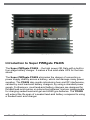
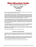
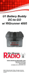
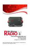
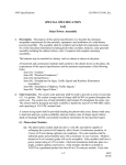
DC-to-GO Battery Box
w/ RIGrunner 4008 and
Super PWRgate PG40S
www.westmountainradio.com
1020 Spring City Drive
Waukesha, WI 53186
262-522-6503
[email protected]
©2015 West Mountain Radio, All rights reserved. All trademarks are
the property of their respective owners.
Thank you for choosing the West Mountain Radio DC-to-GO Battery Box w/
Rigrunner 4008 and Super PWRgate PG40S! You will enjoy powering your
equipment from a portable battery using Powerpole® connectors.
The DC-to-GO gives you convenient portable power. The case accepts
Group Size 24 batteries, providing up to 100 amp hours at 12 volts. Eight
devices may be plugged into the integrated RIGrunner 4008 power strip.
Each socket is fused for protection. Any blown fuse will be illuminated.
Correct and low voltage indicators show battery status. The battery may
be charged via the power strip.
Contents
•
•
•
•
•
•
•
Battery Box with strap
RIGrunner 4008 (mounted directly to battery box)
Super PWRgate PG40S (mounted directly to battery box)
Powerpole® Connection Cable
Battery Lead Cable (2ft. #10 wire, ring terminals to Powerpole®
12 pair pak of 30A Powerpole® connectors and contacts
DC-to-GO Operating Manual
Safety Information
A battery stores a large quantity of energy. A short circuit will release this
energy rapidly causing the wire to melt, and perhaps, catch on fire. Also,
the battery could explode. The fuse located near the battery terminal in the
RIGrunner may help prevent these types of catastrophes.
Batteries
The use of only SAFETY batteries is recommended, such as gelledelectrolyte and absorbed-glass mat (AGM) types. These batteries are sealed
and contain no dangerous gases. These types may be mounted in any
position, although vertical is preferred. They are also 100% maintenance
free.
Use of other types of batteries for portable use in the DC-to-GO is NOT
recommended. Automobile batteries and marine batteries may only be used
if the installation is fixed; where the battery box will not be turned over and
is located outdoors or in a welll-ventilated area.
West Mountain Radio carries high-quality gelled-electrolyte and AGM
batteries. They have posts and lugs with studs to match the ring terminals
on the supply cable provided.
Anderson Power Products® and Powerpole® is a registered trademark of Anderson Power Products, Inc.
West Mountain Radio
2
Operating Manual
DC-to-GO battery box will fit Group Size 24 batteries with the following
dimensions:
Length
10 7/8 in. (276mm)
Width
6 3/4 in. (171mm)
Height
9 7/8 in. (251mm)
Connecting to the Battery
The RED wire with the larger ring terminal is connected to the battery
POSITIVE lug and securely fastened down with the nut. The BLACK wire
with the smaller ring terminal is connected to the battery NEGATIVE lug
and securely fastened down with the nut. Ensure that RED is POSITIVE
and BLACK is NEGATIVE.
Bring the Battery Lead cable out through the front of the battery box to the
Super PWRgate PG40S. Plug into the farthest right connector marked “BAT”.
Neatly fold the excess wire into the box. Next, Plug the Power Connection
Cable into the middle connector on the PG40S marked “OUT” and plug the
other end into the farthest left connector on the RIGrunner 4008 marked
“DCIN”. Make sure the top is oriented so that the large vent is facing the
front. Snap the top into place.
West Mountain Radio carries post-to-stud lug sets. The positive lug matches
the larger size battery post and has a 3/8 inch stud. The negative lug
matches the smaller size battery post and has a 5/16 inc stud.
Using the Strap
The strap may be installed and used both to secure the battery box to the
floor and to restrain the top cover. It also provides the safety precaution in
the event the battery explodes, the plastic box with strap will likely prevent
flying debris and acid.
Note that the strap is easily installed between the RIGrunner and the battery
box.
RIGrunner 4008
There are some considerations to think about. Please read these instructions
carefully before setting up your RIGrunner.
Choosing a mounting location
Pick a location that is close, or central to, most of your radios and
accessories; especially those that draw large amounts of current. Locate
your power source as close as possible to the RIGrunner. Remember that
West Mountain Radio
3
Operating Manual
every wire has resistance, longer wires have more resistance. More than
a 10’ run of #10 wire is not quite adequate to supply the RIGrunner to full
output without a significant voltage drop.
Install in a cool dry place with good ventilation. For example, do not put
it on top of your amplifier or room heater, or cover it with something. It is
recommended to not put it in the engine compartment of your car, or directly
on the floor of a car; rain from open windows or snow covered boots may
cause water damage.
Connecting your equipment
Recognizing that RIGrunner comes standard with Powerpole®, updating
your cables that supply or use 12 volts DC with Powerpole® will improve the
convenience of quick connections and use of your equipment. Remember,
Powerpole® are genderless and the same connector arrangement works
for both supply and load. Powerpole® can be used to charge or power
batteries, all using the same connectors.
Powerpole® can be installed by soldering or crimping. Be sure to make
good connections. For detailed Powerpole® connector installation tips see
RIGrunner support pages at http://www.westmountainradio.com/supportrr.
IMPORTANT!! It is essential that assembly of the pairs is correct. Follow
the amateur radio standard used by the RIGrunner. DO NOT PLUG IN
without verifying that
RED + PLUS and BLACK – MINUS is correct.
The far left connector is labeled DCIN with a 40 amp fuse, and is normally
used to connect to the power supply; but, any output may be used as the
input with an appropriate fuse. Plug in your equipment starting with the
highest power connections to the left and the lower power drain units to the
right, notice the supplied fuse ratings next to the connector chosen. Typically
12 volt input amplifiers and 100 watt RF output transceivers should be first,
VHF radios next and smaller accessories last.
Multiple amplifiers and/or transceivers may be connected to the RIGrunner.
There is a 40 amp maximum that would be exceeded if trying to transmit all
connected units at once. Most radios and amplifiers draw less than 3 amps
in receive, but require many more amps in transmit. Therefore, the limiting
factor is total current draw while transmitting. To determine how many radios
may be used to transmit at one time, consult the radio manual for power
West Mountain Radio
4
Operating Manual
consumption specifications. In the event that the total current goes over the
40 amp maximum, a fuse will blow or make an undersized power supply
unhappy. The RIGrunner and any equipment plugged into the RIGrunner
should go unharmed.
Using the proper fuses
The RIGrunner comes supplied with a range of fuses installed. This assortment
should be suitable for most stations, but can be changed easily. Every RIGrunner
output is safe up to 40 amps, but the total allowable is also 40 amps.
A fuse MUST be in each position in use. ANY ATTEMPT TO BYPASS
OR SHORT ACROSS THE FUSES IS DANGEROUS AND VOIDS THE
RIGRUNNER WARRANTY. Since the maximum available automotive fuse
is 40 amps, the RIGrunner will be protected as long as any value ATC/ATO
fuse is installed. Choose the correct fuse for your equipment. Standard ATC/
ATO automotive blade fuses are used. These fuses are available in 10 values
ranging from 1 amp to 40 amps.
The DC input should have a fuse that is appropriate for the power supply rating.
If using a smaller power supply, consider using a lower value fuse than the 40
amp value supplied. Ideally all of the outlets should have a fuse that is the next
higher value above the maximum current draw of the unit on that fuse. If using a
power cord with a fuse, match that value or go one or two values higher. Sizing
each fuse for each unit is desirable, but not absolutely necessary. Having a
higher value than the minimum will offer less protection for that unit, too low a
value and the fuse will blow out prematurely.
Note that each fuse position has a LED blown fuse indicator that will conveniently
light up if an output fuse is blown. There must be power to the RIGrunner and
a load on the circuit that has the blown fuse for the blown fuse LED to light.
The voltage comparator and audible alert
A feature of the RIGrunner 4012 and 4008 is the precision expanded scale
voltage comparator display with audible alert. (The 4005 and 4004U models
do not have this feature.) A basic explanation of 12 volt systems will aid in
understanding this feature. Equipment commonly referred to as 12 volt is actually
a nominal 13.8 volts. For example, a lead acid battery is a nominal 12.6 volts
when charged and not under load, and approximately 14.0 volts under charge.
A quality 12 volt power supply will have its regulated output set to 13.8 volts.
Most radios are specified to require 13.8 volts +/- 15%. 12 volt automobile or
aircraft alternators have voltage regulation set between 13.5 and 14.3 volts.
West Mountain Radio
5
Operating Manual
The RIGrunner provides an accurate and unambiguous display of voltage. There
are three LEDs: red overvoltage, green normal, and yellow undervoltage. The
points at which the LEDs change are set accurately to 11.5 and 15.0 volts. The
selection of these points gives a reliable indication of proper and safe operation
of your power supply, battery or alternator. A green or normal indication is all
you need to look for.
An undervoltage indication, shown by the yellow LED, is less than 11.5 volts.
This should be safe for your radio, but may cause improper operation. Low
voltage on a modern radio can cause a loss of phase lock and a frequency
error. This is a definite indication of a problem with the power source; a bad
connection, an unregulated power supply, a bad alternator or dying battery. It
is normal with most cars to have less than 11.5 volts when cranking the starter
motor.
A normal indication with the green LED illustrates, everything is good and you
are between 11.5 and 15.0 volts, don’t worry about a thing.
A red overvoltage indication with the red LED is a warning, DISCONNECT OR
TURN OFF YOUR POWER SUPPLY IMMEDIATELY! It is possible to overheat
or damage a radio or other equipment. An overvoltage will sound an audible
alert; no need to watch the LEDs to signal a problem.
When running strictly on a 12 volt battery, an overvoltage condition will not
occur. The RIGrunner’s audible alert can be reconfigured for a low battery
warning. By removing the four cover screws and move the P14 jumper to the
“LO” position. Remember to move it back to “HI” when changing back operation
from power supply or alternator.
Note: Due to the characteristics of the comparator chip it is normal for the
undervoltage LED to glow very dimly with a normal or overvoltage indication.
It is also normal for the LEDs to change intensity while stepping through 10
precision points.
In the event of a bad power source or power connection, the yellow LED may
flash or come on during transmit. If this happens, check the power source
and connections. It is also possible for RF from a transmitter to cause
an electronically regulated power supply to lose regulation and cause an
overvoltage alert during transmit. The RIGrunner is extensively RF bypassed
and should actually cure this problem. If you do have an overvoltage condition
during transmit especially with a VHF high power amp, it is due to inadequate
RF filtering on the DC lead of the amplifier, or poor RF immunity of the power
supply regulator circuit.
West Mountain Radio
6
Operating Manual
RIGrunner Accessories
Order Sku#
Fuse Assortment Low Value (8pcs) #58537-1085
3- 1A, 3- 5A & 2- 10A
Fuse Assortment High Value (8pcs)
2 ea. of 15A, 20A, 30A, 40A
#58537-1086
Buss 10A ATC Circuit Breaker
Buss 15A ATC Circuit Breaker
Buss 20A ATC Circuit Breaker
Buss 25A ATC Circuit Breaker
Buss 30A ATC Circuit Breaker
#58537-1087
#58537-1088
#58537-1089
#58537-1090
#58537-1091
Powerpole® Extension Cable, 3 ft.
#12 Red/Black Wire w/ Powerpole® ends
#58531-1082
Powerpole® Extension Cable, 6 ft.
#12 Red/Black Wire w/ Powerpole® ends
#58531-1083
Powerpole® Extension Cable, 10 ft.
#12 Red/Black Wire w/ Powerpole® ends
#58531-1084
15A. Powerpole® Connector-12 Pair
#58257-1093
30A. Powerpole® Connector-12 Pair
#58257-1095
45A. Powerpole® Connector-12 Pair
#58257-1099
Powerpole® Retention Clips - 12 Pack
#58257-1092
PowerLock - RIGrunner Retainer Kit
#58512-1060
PWRcrimp Crimp Tool
#58568-1049
To purchase or view other accessories available,
call or go online at:
www.westmountainradio.com/shop
West Mountain Radio
7
Operating Manual
Introduction to Super PWRgate PG40S
The Super PWRgate PG40S….the high power OR Gate with a built-in
four-stage battery charger. It makes a true solid-state UPS for the ham
shack.
The Super PWRgate PG40S eliminates the danger of connecting a
power supply directly across a battery, which can damage many power
supplies. The PG40S also avoids introducing hum and RF interference,
caused by most lead-acid battery chargers, by using a standard power
supply. Furthermore, most lead-acid battery chargers are designed for
flooded lead-acid marine or automotive batteries, and are inappropriate
for charging sealed lead-acid gel and AGM type batteries. The PG40S
will extend the life span of a sealed lead-acid battery compared to using
a flooded lead- acid charger.
West Mountain Radio
8
Operating Manual
The PG40S transfers 40 amperes at 12 volts DC in a continuous safe
manner. It connects a battery and a power supply to a load, while
electrically isolating both the battery and the supply from each other.
Whenever the power supply is on, the supply feeds the load. It also
charges the battery with a high-current four-state safe battery charger.
Whenever the power supply is off, the battery will feed the load. If either
the power supply or the battery is malfunctioning, neither draws current
from the other. The switching is instantaneous.
A PG40S is very useful in the ham shack, and even more useful in a
repeater installation. Communication equipment will remain operative
during AC power blackouts and power supply failures. Power supplies
and batteries can be swapped out while equipment continues to be
powered and without glitches.
Additionally, the PG40S and a power supply may be used solely as a
permanently installed battery charger. This also may be configured to
run a radio station directly from the battery. (See the article by W1ZR in
QST, December 2003 at www.westmountainradio.com/. . . )
Please read the following instructions
BEFORE installing the PG40S
Choosing a Mounting Location
Pick a location that is close or central to the power supply, battery,
as well as the load or 12V distribution panel. Radios and many 12V
devices draw large amounts of current. All wires have resistance, so it
is good practice to keep them as short as possible and to use a larger
gauge wire to minimize voltage drop.
The PG40S can be installed in any orientation. It is recommend to
use in a cool dry location and preferably well ventilated. Do not tightly
enclose the unit as the heat sink can become quite warm under
maximum current. At 40A continuous current it will rise about 40
degrees Fahrenheit over ambient temperature in free air. If placed in
direct sunlight, it will absorb heat and get unnecessarily hot.
The Super PWRgate can be mounted using number 8 hardware in the
two mounting holes.
West Mountain Radio
9
Operating Manual
Connecting the power supply
Use a regulated power supply that is between 13.8 volts and 15 volts.
Anderson Powerpole® are used for all Super PWRgate connections.
See the section “Powerpole® connector installation tips”.
The power supply wire should be heavy gauge and as short as possible;
recommend #10 wire 3 feet to no longer than 6 feet long. Most power
supplies have 1/4 inch studs. Note that West Mountain Radio carries 3
and 6 feet long power supply cables, #10 red and black insulated wire
with ¼” in ring terminals on one end and Powerpole® on the other.
Be sure to connect the RED Powerpole® connects to the RED wire and
connect to the PLUS terminal on the supply. Similarly, make sure that
the BLACK Powerpole® connect to the BLACK wire and connect to the
NEGATIVE terminal on the supply. Check that the connections at the
power supply are well tightened.
Plug this cable from the power supply into the Super PWRgate
connector marked PS (power supply). Confirm that the Powerpole® are
plugged together securely, and that the wire is straight at the connection
point and is not under strain or bent over.
Transceiver
Super PWRgate PG40s
Power Supply
West Mountain Radio
Battery
10
Operating Manual
Connecting the Load or Power Strip
Anderson Powerpole® are used for all Super PWRgate connections. See
the section “Powerpole® connector installation tips”.
The load wire should be heavy gauge and as short as possible. If
connecting directly to a radio or other device, you will need to install
Powerpole® on those cords. Modern radios use RED wire for positive,
and BLACK wire for negative (or common or ground). Refer to the
equipment manual if you have non-standard equipment. Plug this wire
into the Super PWRgate terminal marked OUT.
If you are connecting the output to a power strip, such as a RIGrunner, it
is recommended to use #10 wire, 3 feet to 6 feet long. At least one end
will need Powerpole® installed; the other end can wire directly to the
power strip or use connectors. Note that West Mountain Radio carries 3
feet and 6 feet long extension cables, #10 red and black insulated wire,
with Powerpole® on both ends.
Plug this wire from the power strip or equipment into the Super PWRgate
connector marked OUT (output). Confirm that the Powerpole® are
plugged together securely, and that the wire is straight at the connection
and is not under strain or bent over.
At this point, check out the system operation with the power supply. Turn
on the power supply and turn on the radio or equipment. The radio or
equipment should properly work.
Connecting the Battery
Anderson Powerpole® are used for all Super PWRgate connections. See
the section “Powerpole® connector installation tips”.
The battery wire should be heavy gauge and as short as possible;
recommend #10 wire, 3 feet long. In addition, a fuse must be installed
in the positive lead directly at the battery terminal. Note, any short in
the battery wire, connector, or load could result in fire and battery
explosion.
West Mountain Radio
11
Operating Manual
Large batteries have side, post, or threaded terminals. Deep cycle,
marine, AGM, and others usually have 3/8 inch and 5/16 inch studs.
Therefore, it is recommended to use a short 3 feet #10 wire, Powerpole®
on one end, an in-line fuse (40 A max), and ring terminals for the
battery end. West Mountain Radio carries a battery fuse kit, wire, and
Powerpole®.
Batteries
Caution: Handle batteries with knowledge and appropriate care.
Batteries have dangerous chemicals that can seep out. Batteries can
emit extremely explosive hydrogen gas that is explosive. Batteries,
especially automotive and marine flooded lead acid, must be used in
a strong, ventilated enclosure. Sealed lead acid batteries are much
safer but must be correctly handled with care.
NEVER make the last connection directly to a battery causing a
spark that could cause the battery to explode, sending debris and
acid in all directions. Batteries can get very hot when improperly
charged or if a cell gets shorted. Batteries will explode during
charging or discharging for a variety of reasons. Batteries are safe
when handled properly.
Choose a 12 volt battery with an ampere-hour rating according to your
power needs. If the batteries are placed indoors they must be sealed for
safety reasons. Again, it is very important to place a fuse at the positive
battery terminal.
This manual does not cover all the types of batteries, but for use in the
ham shack a lead-acid types battery is recommended because they offer
the best price to power ratio. Gelled cells and absorbed glass mat (AGM)
batteries are sealed and are very safe. Some of these have a tiny positive
pressure vent. Gelled cells are best to use with the Super PWRgate
because the battery charging circuit comes configured properly and
matches a 13.8 volt power supply. If using AGM batteries, it is suggested
to slightly elevate the voltage for the power supply, and add a jumper
change inside the Super PWRgate. It is not recommended to use other
types of batteries, such as “starting”, “deep cycle” and “marine” batteries,
or automobile batteries.
For additional information on batteries visit this website:
www.windsun.com/batteries/battery_FAQ.htm
West Mountain Radio carries size 24 Gelled and AGM batteries.
West Mountain Radio
12
Operating Manual
System Checkout
When the power supply and battery are connected, and the Super
PWRgate is driving a radio, a quick checkout procedure should be followed:
· Run your radio, and unplug the power supply. The radio should
operate without interruption now from the battery.
· Plug the power supply back in, and the radio will now be powered
from the supply. If you have an ammeter on the supply it will show
current.
It is recommended to use and in-line meter, such the Power Analyzer sold
by West Mountain Radio. It measures volts, amperes, watts, amperehours, and watt-hours simultaneously.
Place the Power Analyzer in-line with the power supply to measure its
output. Unplug the load from the Super PWRgate to measure the battery’s
charging current. Plug the Power Analyzer into the Super PWRgate’s output
to measure either the power supply current if the supply is connected, or
the battery’s output current if the supply is disconnected or is turned off.
Refer to the charging circuit description to verify the different states when
measuring the charging current.
Voltages
Manufacturers list the lowest recommended DC supply voltage range for
the specific radio model. Some radios are listed as 13.8 VDC +- 15%, and
others as 13.8 VDC +-10%.
12 volt power supplies are regulated to provide 13.8 volts DC. The Super
PWRgate has a diode in series that has a voltage drop of 0.25 V for 50
ma to 0.30 V for 1 ampere and 0.50V at 40 amperes. Under normal load
the Super PWRgate output will be no less than13.5 volts.
Fully charged 12 volt batteries exhibit around 13.5 volts open circuit.
When supplying current, the battery’s internal resistance diminishes
the voltage. For instance, a 70 A-h battery will drop to 12.3 volts at 10
amperes at half discharge. The Super PWRgate will give a drop of 0.3
volts at 1 ampere, thereby providing 12.0 volts to the radio.
Additional voltage drops can easily occur due to the high current and
the resistance in the wires, the fuses, and the connectors. Therefore, it
is imperative to keep all wires as short as possible, as low of gauge as
practical, and as few connectors as possible. Also use a large fuse on
the battery, 30 or 40 amp to keep its voltage drop low. Use a voltmeter to
check the voltage at the radio when running on battery power.
West Mountain Radio
13
Operating Manual
Super PWRgate Charger
The charging circuit is a four-state high-current battery charger. The
charging circuit, which is always connected to the battery, uses the
power supply as the current source. It charges the battery automatically
by knowing the battery’s voltage. It also changes charging state if the
power supply goes from “off” to “on”, following a power outage, and it
also changes state if the battery voltage drops when supplying heavy
current. These conditions are interrelated to provide proper charging
automatically.
The charger is a safe battery charger. It supplies the rated current
if the battery is heavily discharged. Current drops in a smooth and
progressively diminishing manner as the battery nears full charge. Note,
that the charger is a feedback device and it cannot overcharge a 12 volt
battery. Also, it will not charge a battery that has a dead cell.
The charging circuit has four selectable charging current settings, 1A, 4A,
7A, and 10A, to be chosen appropriately for the battery’s rating.
Typical Charging Curve
GREEN LED
MAX
CURRENT
Check for
bad cell
GREEN & RED LED
GREEN & YELLOW LED
Switch to Float
@ 0.1 MAX
FLOAT CURRENT
TIME
West Mountain Radio
14
Operating Manual
The four charging states are:
Trickle charge…If the battery is below 10 volts, then a low current of
50 ma is supplied. This is a safe current if the battery has a dead cell.
But if the battery is good, the voltage will slowly rise to above 10 volts
and then the charger will switch to the bulk charge state.
Bulk Charge…. This is a high current state, selected by the maximum
current setting (Fuse Jumper), and controlled by the battery’s voltage.
The charger will provide up to maximum current, limited by the circuit,
the power supply voltage, and the battery’s impedance and voltage.
Peak Voltage…. This is often called the “absorption” state. The battery
is charged with the voltage limit elevated to 3.8 V or 14.2 V (see below),
until the current has diminished to a tenth of the maximum setting. At
this current, the charger will change to the float state.
Float….. This is the resting state of the charged battery, often called
the maintenance state. The charger will supply sufficient current, up to
the maximum selected current, to keep the battery at the float voltage of
13.5 V.
The states are switched as follows:
Turn-on…. If the power supply is turned on, and the battery had been
discharged below 10 volts, the charger will start in the trickle charge
state, and then, if the battery rises above 10 volts, it changes into the bulk
charge state. If the voltage rises to above 12 volts, then the peak voltage
state is entered. Then, when the current has diminished to one-tenth of
the maximum selected current, the float state is entered. If the battery
is charged to over 13 volts, turning on the power supply will cause the
charger to remain in the float state.
This turn on cycle occurs following a power outage.
West Mountain Radio
15
Operating Manual
Discharging Battery…. If a load is placed on the battery, and the charger
had been in the float state, and the battery voltage stays above 13 volts,
the charger will remain in the float state supplying up to full current. If
the battery voltage is discharged to less than 12 volts, and the load is
removed, the charger will enter the peak voltage and eventually the float
state as above.
If the radio station is connected directly to the battery and not through
the Super PWRgate output, then the battery will supply the load while
the battery is being charged. In fact, the current will be shared between
the load and the battery. This method of powering a radio station was
described by W1ZR in an article in QST, Dec 2003. See the diagram
below for aW1ZR configuration.
Transceiver
Super PWRgate PG40s
Power Supply
West Mountain Radio
Battery
16
Operating Manual
LED Indicators
Green (ON)…. Indicates that the charger is fully active and will provide
up to maximum current to the battery according to the battery’s state.
Note that this LED does not measure nor indicate current flow, only the
charger’s state, ie. “fully active state and would charge a battery if it were
connected.“
Green (ON) and RED (PK)…. Indicates that the charger is in the peak
voltage state (PK) and will provide up to maximum current to the battery.
As the current is diminishing the charger attempts to reach an elevated
battery voltage. When the current drops to one-tenth the maximum
current setting the state changes to float.
Green (ON) and Yellow (FL)…. Indicates that the charger is in the
float state (FL) and will provide up to maximum current to the battery to
maintain the battery at the float voltage of 13.5 volts.
A typical charging curve is shown in the figure.
Choosing and Setting the Maximum Charge Current
The charger has three internal current sensing resistors that can be
activated for determining the maximum current limit. 40A fuses are used
as the high current switch (need a high current jumper wire. The 40A fuse
has the lowest resistance of the ATC fuses and closely approximates a
true jumper.) Note that leaving the fuses out provides a charge current
of 1 ampere. To get different charging current values install the fuses as
follows.
1 Ampere….. No fuse
4 Amperes……Fuse in left socket
7 Amperes…….Fuse in right socket
10 Amperes……Fuse in both sockets
Use the following charging current for the listed lead-acid battery ratings.
Use 1 ampere for batteries from 3 to 12 Ah.
Use 4 amperes for batteries from 13 to 32 Ah.
Use 7 amperes for batteries from 33 to 50 Ah.
Use 10 amperes for batteries from 51 Ah up.
West Mountain Radio
17
Operating Manual
Advanced Charger Considerations
Gelled Cells
The battery charger uses the station power supply. For ham radio operators
this is usually a 13.8 volt supply. Because of circuit components, this limits
the peak charge voltage to around 13.6 volts, which is slightly less than
a desired 13.8 volts for a gelled cell’s peak. This results in a slightly low
absorption state. The battery’s charge, therefore, will be a few percent less
than maximum available ampere-hours.
To achieve optimum battery charging, the power supply should be
adjusted to 14.10 volts dc. The charger will now permit the battery to
reach a peak voltage of 13.8 volts during the peak voltage cycle. The float
state will remain at 13.5 Volts.
Note: Always use a accurate digital display voltmeter to assure accurate
readings.
AGM Cells
The charger can also be configured for an AGM type sealed battery.
To do this precisely, the power supply should be re-adjusted to provide
14.50 volts. In addition, a jumper must be installed at J1 inside the Super
PWRgate. Take the top cover off. The small blue jumper block should be
lifted off the pin and re-installed shorting out the two pins. The charger will
now permit the battery to reach a peak voltage of 14.2 volts during the
peak voltage cycle. The float state remains at 13.5 volts.
Note: Always use a accurate digital display voltmeter to assure accurate
readings.
Note that all major radio manufacturers specify that their radios will
operate up to 15 Volts DC. Therefore using the Super PWRgate at an
elevated voltage of 14.5 volts is fine.
West Mountain Radio
18
Operating Manual
Specifications
Maximum Voltage:
Maximum Current:
Circuit: Diodes:
Voltage Drop: Charging Circuit:
Connectors:
Size:
Weight:
Mounting Holes: 18 Volts DC
40 Amperes
Diode OR-Gate
Two Schottky 80 Ampere, 20 Volt
0.25 VDC Quiescent
0.50 VDC at 40 Amperes
Charging regulator IC
Field Effect Pass Transistor
Schottky Diode
Fuse switched for 1, 4, 7, or 10 Amperes (+2,-8%) maximum
Peak voltage limit: 13.8 (Gelled Cells),
14.2 (AGM), (+,-2%)
Peak voltage terminate point: 1/10 max. current
Float Voltage: 13.5 volts (+,-2%)
Reference voltages are temperature compensated
Anderson Powerpole®, 40A
5.25 x 3.90 x 1.65 in, 13.4 x 9.9 x 4.2 cm
0.9 lbs, 0.4 kg
Two, 0.175 d, at 4.875 in. distance, for #8 hardware
West Mountain Radio
19
Operating Manual
Powerpole® Wiring Guide
Powerpole® Series
Contact
Recommended Wire
Gauge
15 A
20-16 AWG
30A
20-12 AWG
45A
14-10 AWG
Additional Resources for Anderson Powerpole®
go to: www.andersonpower.com
Details and a video demonstration for using PWRcrimp Tool with
Powerpole®, go to:
www.westmountainradio.com/crimptool
DC-to-GO Battery Box w/ RIGrunner 4008
and Super PWRgate PG40S Warranty
DC-to-GO model is warranted against failure due to defects in workmanship or materials for
one year after the date of purchase from West Mountain Radio. Warranty does not cover
damage caused by abuse, accident, misuse, improper or abnormal usage, failure to follow
instructions, improper installation, alteration, lightning, or other incidence of excessive voltage
or current. If failure occurs within this period, return the DC-to-GO model or accessory to
West Mountain Radio at your shipping expense. The device or accessory will be repaired
or replaced, at our option, without charge, and returned to you at our shipping expense.
Repaired or replaced items are warranted for the remainder of the original warranty period.
You will be charged for repair or replacement of the Super PWRgate PG40S or accessory
made after the expiration of the warranty period.
West Mountain Radio shall have no liability or responsibility to customer or any other person
or entity with respect to any liability, loss, or damage caused directly or indirectly by use or
performance of the products or arising out of any breach of this warranty, including, but not
limited to, any damages resulting from inconvenience, loss of time, data, property, revenue,
or profit, or any indirect, special incidental, or consequential damages, even if West Mountain
Radio has been advised of such damages.
Except as provided herein, West Mountain Radio makes no express warranties and any
implied warranties, including fitness for a particular purpose, are limited in duration to the
stated duration provided herein.
www.westmountainradio.com
1020 Spring City Drive, Waukesha, WI 53186
tel 262-522-6503 fax 262-522-6504