1
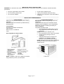
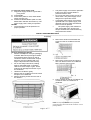
WINDOW
AIR CONDITIONER
INSTALLATION
AND
OPERATION
CATALOG NO.
WA18ZR
WA24ZR
PRODUCT CODE
420-0068
420-0071
950-0052-revB
CATALOG NO.
PRODUCT CODE
WA24ZM
420-0072
1-10-07
Page 1 of 17
TABLE OF CONTENTS
AIR CONDITIONER SAFETY………………………………………………….….2
INSTALLATION REQUIREMENTS………………………………………………3
INSTALLATION INSTRUCTIONS………………………………………………..5
THRU-THE-WALL CABINET INSTALLATION…………………………………9
AIR CONDITIONER USE…………………………………………………………11
AIR CONDITIONER CARE……………………………………………………….13
TROUBLESHOOTING………………………………………………………….…14
SPECIFICATIONS…………………………………………………………………16
WARRANTY………………………………………………………………………...17
TECHNICAL SUPPORT
IF YOU NEED TECHNICAL SUPPORT, PLEASE CALL (705) 504-8590 BETWEEN THE HOURS OF 8:00 A.M. and
5:00 P.M. EST.
PLEASE HAVE THE MODEL NUMBER AND SERIAL NUMBER OF YOUR EQUIPMENT AVAILABLE WHEN YOU
CALL.
AIR CONDITIONER SAFETY
Your safety and the safety of others is very important
We have provided many important safety messages in this manual and on your appliance.
Always read and follow all safety instructions.
This is the safety alert symbol.
This symbol alerts you to potential hazards that can kill or hurt you or others.
All safety messages will follow the safety alert symbol and the word “DANGER” or
“WARNING”.
These words mean:
You can be seriously injured if instructions are not
followed.
Bodily injury or damage to personal property may
occur if instructions are not followed.
All safety messages will tell you what the potential hazard is, tell you how to reduce the chance of
injury, and tell you what can happen if the instructions are not followed.
Page 2 of 17
IMPORTANT SAFETY INSTRUCTIONS
WARNING: To reduce the risk of fire, electrical shock or injury when using your air conditioner, follow these basic
precautions:
•
•
•
•
•
•
Plug into a grounded 3 prong outlet.
Do not remove ground prong.
Do not use an adapter.
Do not use an extension cord.
Unplug Air Conditioner before servicing.
Use two or more people to move and install air
conditioner.
___________________________________________________________________________________________
INSTALLATION REQUIREMENTS
________________________________________
________________________________________
Location Requirements
Tools and Parts
IMPORTANT: Observe all governing codes and
Gather the required tools and parts before starting
ordinances.
installation.
Check the location where air conditioner will be
Read and follow the instructions provided with any
installed. Proper installation is your responsibility.
tools listed here.
Make sure you have everything necessary for
correct installation.
Tools Needed:
The location should provide:
Flat-blade and Phillips Screwdrivers
Tape measure
• Grounded electrical outlet within 4 ft (122
Drill and 3/16” or smaller bit
cm) of where the power cord exits the air
Level
conditioner.
NOTE: Do not use an extension cord.
Parts supplied (on some models)
• Free movement of air in room to be cooled.
• A large enough opening for the air
conditioner.
• Adequate wall support for weight of air
conditioner. Air conditioner weights
between 145 and 200 lbs (65 to 96 kg).
NOTE: Cabinet louvers must not be obstructed.
Air must be able to pass freely through the
cabinet louvers.
NOTE: Installation parts are supplied for doublehung windows up to 40: (101.6cm) wide.
Page 3 of 17
_____________________________________
WINDOW INSTALLATION
_____________________________________
Window Opening Measurements:
• 30” min to 40” max. opening width.
• 20” Min. opening height.
_____________________________________
Electrical Requirements
_____________________________________
Recommended Grounding Method
This air conditioner must be grounded. This air
conditioner is equipped with a power supply
cord having a grounded 3 prong plug. To
minimize possible shock hazard, the cord must
be plugged into a mating, grounded 3 prong
outlet, grounded in accordance with all local
codes and ordinances. If a mating outlet is not
available, it is the customer’s responsibility to
have a properly grounded 3 prong outlet
installed by a qualified electrical installer.
It is the customer’s responsibility:
• To contact a qualified electrical
installer.
• To assure that the electrical
installation is adequate and in
conformance with National Electrical
Code, ANSI/NFPA 70- latest edition,
and all local codes and ordinances.
Copies of the standards listed may be obtained
from:
National Fire Protection Association
One Batterymarch Park
Quincy, MA 02269
_____________________________________
Power Supply Cord
_____________________________________
NOTE: Your unit’s device may differ from the
ones shown.
This room air conditioner is equipped with a
power supply cord required by UL. This power
supply cord contains state-of-the-art
electronics that sense leakage current. If he
cord is crushed, the electronics detect leakage
current and power will be disconnected in a
fraction of a second.
Page 4 of 17
To Test your power supply cord:
1. Plug power supply cord into a grounded 3
prong outlet.
2. Press RESET
3. Press TEST (listen for click, Reset button
will trip and pop out).
4. Press and release RESET (listen for click;
Reset button will latch and remain in). The
power supply cord is ready for operation.
NOTES:
• The reset button must be pushed in for
proper operation.
•
The power supply cord must be replaced if
it fails to trip when the test button is
pressed or fails to reset.
• Do not use the power supply cord as an
off/on switch. The power supply cord is
designed as a protective device.
• A damaged power supply cord must be
replaced with a new power supply cord
obtained from the product manufacturer
and must not be repaired.
•
The power supply cord contains no
user serviceable parts. Opening the
tamper-resistant case voids all warranty
and performance claims.
INSTALLATION INSTRUCTIONS
________________________________________________________________________________________
Unpacking
3. Remove the window lock bracket and
screw from the air conditioner and set
aside.
Remove packaging materials
• Remove and dispose of/recycle packaging
materials. Remove tape and glue residue
from surfaces before turning on the air
conditioner. Rub a small amount of liquid
dish soap over the adhesive with your
fingers. Wipe with warm water and dry.
• Do not use sharp instruments, rubbing
alcohol, flammable fluids, or abrasive
cleaners to remove tape or glue. These
products can damage the surface of your
air conditioner.
• Handle air conditioner gently.
1. Remove the air conditioner from the carton
and place it on cardboard.
2. Remove shipping screws from the rear of
the cabinet.
4. Remove the ground screw and ground
wire from the front of the air conditioner
base. Save the ground screw.
5. Pull on handles to slide air conditioner out
of cabinet. Place air conditioner on
cardboard.
NOTE: Do not push, pull or remove any expanded
polystyrene (foam) from inside the air conditioner. It is not
packing material.
Page 5 of 17
________________________________________________________________________________________
Window Installation (on some models)
NOTES:
• Handle air conditioner gently.
• Be sure your air conditioner cabinet does
not fall out of the opening during
installation or removal.
• The place where the power cord exits the
air conditioner should be no more than 4 ft
(122 cm) from a grounded 3 prong outlet.
• Do not block the louvers on the front panel.
• Do not block the louvers on the outside of
the air conditioner.
•
Attach Top Channel
NOTE: Attach top channel and side curtains to
air conditioner cabinet before placing cabinet
in window.
• Locate provided bag of screws.
• Place top channel on top of air conditioner
cabinet, lining up the 4 holes in top
channel with the 4 holes on top of air
conditioner cabinet.
• Using 4 - #10 x 3/8” washer-head Phillips
thread cutting screws, attach top channel
to air conditioner cabinet.
Extend right-hand curtain outward so you
may insert the first screw through the
middle hole of the curtain. Using #10 x ¼”
pan-head Philips screw, screw curtain to
middle hole in air conditioner cabinet.
NOTE: This screw is required to correctly
attach curtain (top to bottom) to the air
conditioner cabinet.
•
Attach Side Curtains
• Locate provided bag of screws.
• Insert top and then bottom of right-hand
curtain housing in top and bottom curtain
channels on air conditioner.
Page 6 of 17
While the right-hand curtain is still
extended, insert #10 x ¼” pan-head
Phillips screws into the top and bottom
slots of curtain. Screw curtain to the top
and bottom holes in the air conditioner
cabinet.
• Slide the curtain housing into the curtain
channels as far as it will go.
• Repeat above steps for the left hand
curtain.
Attach foam adhesive seal
Attach foam adhesive seal along the bottom of
the curtain bottom channel.
Install Cabinet into Window
Attach Side Curtains to Window Frame
•
•
1. Pull Left-hand curtain out until it fits into window
channel. Use a 3/32” drill bit to drill a starter hole
through the hole in the curtain housing and into the
lower window sash.
Handle air conditioner gently.
Be sure your air conditioner cabinet does
not fall out of the opening during
installation or removal.
• The place where the power cord exits the
air conditioner should be no more than 4 ft
(122 cm) from a grounded 3 prong outlet.
• Do not block the louvers on the front panel.
• Do not block the louvers on the outside of
the air conditioner.
1. Center empty cabinet in window. Check
that lower rail of air conditioner cabinet is
behind and against back side of windowsill.
Maintain a firm hold on the air conditioner
cabinet. Lower window sash to hold
cabinet in place.
2. Measure the distance between the righthand side of the cabinet and the inside of
the window channel.
3. Repeat for the left side. Adjust the cabinet
until the distance on each side is the same.
2. Insert one of the #10 x ¾” round-head screws
through the threaded hole in the top of the curtain.
4. use a 3/16” drill bit to drill 4 starter holes
3/8” deep- through the 4 holes in the
cabinet and into the windowsill.
5. Attach cabinet to windowsill with 4 - # 10 x
½” pan-head Phillips screws.
3. Repeat for right-hand curtain.
1.
Attach support Brackets
Attach support brackets to the cabinet by aligning
the holes in the bracket with the holes in the
cabinet.
6. Check that air conditioner cabinet is tilted
to the outside so that water will run to the
outside.
Page 7 of 17
2. Insert air conditioner into cabinet.
2. Using #10 x 7/8” pan-head Phillips screws,
attach bracket to cabinet. Repeat for other
bracket.
3. Turn the adjustment bolt for each bracket until
the bolt touches the wall.
4. Turn the locking nut on adjustment bolt to lock
in positions.
3. Connect green ground wire to cabinet base
with ground screw. Position ground wire
pointing straight up. Put excess ground wire
between coil and air conditioner cabinet.
4. Push Front panel straight on and then lower it
slightly to lock it into place.
Complete Installation
1. Insert seal behind the top of the lower window
sash and against the glass of the upper
window.
2. Place one window-lock bracket on top of lower
window and against upper window sash on
each side of window.
3. Use a 3/32” drill bit to drill starter holes through
the holes in each bracket into the window sash.
4. Attach both window-lock brackets to window
sash with a #10 x ¾” round-head screw to
secure window in place.
Final Installation
NOTE:
1.
Make sure the free end of the ground wire is
outside of the cabinet.
Page 8 of 17
5. Using 2 # 10 x 3/8” round head screws, attach
bottom of front panel.
Through-the-Wall Cabinet Installation
NOTES:
• Use 1” (2.5cm) or thicker lumber for wood
frame.
•
Handle air conditioner gently.
•
Be sure your air conditioner does not fall out of
4. Apply wood preservative to the outside
the opening during installation or removal.
exposed surfaces.
•
The place where the power cord exits the air
conditioner should be no more than 4 ft
(122cm) from a grounded 3 prong outlet.
•
It is the customer’s responsibility and
obligation to have this product installed by a
qualified technician familiar with through-thewall room air conditioner installations.
•
Do not block the louvers on the front panel.
•
Do not block the louvers on the outside of the
air conditioner.
Option 1 – Wood, Metal or Plastic molding
When using a wood, metal or plastic molding, the
5. Insert the frame in the wall opening. Square
wood frame should line up with inside wall as shown,
and level frame.
6. Attach frame securely to the wall.
INSTALL CABINET INTO WOOD FRAME
1. Remove top channel and both side channels
using a ¼” nut driver or socket wrench.
Discard top channel and both side channels.
Option 2 – Plastered wall with no molding
If the plastered wall is to be flush with the cabinet
and no molding used, the wood frame must be set
½” 913mm) into the inside wall.
Install Wood Frame
1. Construct wood frame. See “Location
Requirements” for dimensions.
2. Measure outside width and height of frame
to determine wall opening dimensions.
3. Cut opening through the wall. Remove and
save insulation.
• Dimension for depth depends on wall
thickness and type of molding.
• Do not block louvers in air conditioner
cabinet.
Page 9 of 17
2. Insert cabinet into the framed wall opening.
The top of the cabinet should extend ¾”
(19.1 mm) into the room. If there is trim, the
cabinet should extend ¾” (19.1mm) past the
trim.
3. Use a level to check that the unit is level side
to side.
4. Check that air conditioner cabinet is tilted to
the outside so that water will run to the
outside.
5. Reuse the insulation to seal opening
between cabinet and frame.
6. Use existing holes in sides and top of
cabinet and 7 #10 x 1” wood screws (not
provided) to attach cabinet to frame.
NOTE: Do not over-tighten screws or
cabinet will distort and provide a poor seal
between cabinet and air conditioner.
7. Caulk all outside wall openings around
cabinet.
Complete Installation
1. Insert seal behind the top of the lower
window sash and against the glass of the
upper window.
2. Place one window-lock bracket on top of
lower window and against upper window
sash on each side of window.
3. Use a 3/32” drill bit to drill starter holes
through the holes in each bracket into the
window sash.
4. Attach both window-lock brackets to window
sash with a #10 x ¾” round-head screw to
secure window in place.
Final Installation
NOTE:
5. Make sure the free end of the ground wire
is outside of the cabinet.
Page 10 of 17
6. Insert air conditioner into cabinet.
7. Connect green ground wire to cabinet
base with ground screw. Position ground
wire pointing straight up. Put excess
ground wire between coil and air
conditioner cabinet.
8. Push Front panel straight on and then
lower it slightly to lock it into place.
9. Using 2 # 10 x 3/8” round head screws,
attach bottom of front panel.
AIR CONDITIONER USE
1.
Operating your air conditioner properly helps you
obtain the best possible results.
This section explains proper air conditioner operation
IMPORTANT:
• If you turn off the air conditioner, wait at least
3 minutes before turning it back on. This
prevents the air conditioner from blowing a
fuse or tripping a circuit breaker.
• Do not try to operate your air conditioner in
the cooling mode when outside temperature
is below 65ºF. The inside evaporator coil will
freeze up, and the air conditioner will not
operate properly.
NOTE:
In the event of a power failure, your air conditioner
will operate at the previous settings when the power
is restored.
Touch Control Panel
Lights next to the touch pads on the air conditioner
control panel indicate the selected settings.
Air Conditioner Controls
Power pad – Turns the air conditioner on and
off. When turned on, the display will show the
room temperature.
2. Display – Shows the room temperature or time
remaining on the Delay timer. Shows the Set
temperature while setting the temperature in
Cool or Energy Saver modes. The Set light will
turn on while setting.
NOTE: The display will change to show the room
temperatures after settings have been made. To
recall the Set temperature, press the Temp Increase
or Decrease pads.
3. Increase “▲”pad – Used to increase set
temperature when in Cool or Energy Saver
mode. The Set light will turn on while setting.
Used to increase the delay time when using the
Timer function.
4. Decrease “▼” pad –Used to decrease set
temperature when in Cool or Energy Saver
mode. The Set light will turn on while setting.
Used to decrease the delay time when using the
Timer function.
5. Fan Speed pad – Used to select the fan speed.
The lights marked “High”, “Med”, or “Low” will
illuminate to indicate which fan speed is selected.
6. Mode pad – Used to select between Fan only or
Cool mode of operation. In the Fan only mode,
since Fan only settings do not provide cooling, a
Set temperature can not be entered. The display
will indicate the room temperature.
7. Circulaire pad – Used to turn on the side-to-side
air circulation. For fixed side-to-side air direction,
turn on until the desired air direction is obtained,
then turn off.
Model WA18ZR
8. Timer/Delay pad – Used to select the amount of
time before the air conditioner turns off (when
on), or the amount of time before the air
conditioner turns on (when off). Programmable in
1 hour increments from 1 to 24 hours.
How to set the Timer:
Delayed “ON”;
Air Conditioner must be off.
Press the Timer/Delay button.
The Timer/Delay light will turn on and the display will
indicate the number of hours before the air
conditioner will turn on. To change the time before
turn on, press the Increase “▲” or Decrease “▼”
pads until the desired number of hours before turn on
is reached (1 to 24 hrs).
Model WA24ZR
Page 11 of 17
Delayed “OFF”:
Air Conditioner must be on.
Press Timer/Delay button.
The Timer/Delay light will turn on and the display will
indicate the number of hours before the air
conditioner will turn off. To change the time before
turn off, press the Increase “▲” or Decrease “▼”
pads until the desired number of hours before turn on
is reached (1 to 24 hrs).
To review the amount of time remaining on the timer,
press the Timer/Delay pad one time. If you desire to
increase or decrease the amount of time remaining,
use the Increase “▲” or Decrease “▼” pads to set
a new time.
To cancel the Timer, press the Timer/Delay pad
until the Timer/Delay light extinguishes.
the Energy Saver mode off, and the fan runs all the
time, while the compressor cycles on and off.
10. Fan Only Mode:
Use the Fan Only Mode at Low, Med or High
fan speed to provide air circulation and filtering
without cooling, a Set temperature cannot be
entered. The room temperature will appear in the
display.
NOTE: Auto Fan Speed cannot be used when in
the Fan Only Mode.
11. Auto Fan Speed:
Set to Auto fan speed for the fan speed to
automatically set to the speed needed to provide
optimum comfort settings with the set
temperature.
If the room needs more cooling, the fan speed
will automatically increase. If the room needs
less cooling, the fan speed will automatically
decrease.
NOTE: Auto Fan Speed cannot be used when in the
Fan Only Mode.
9. Energy Saver pad – used to control the fan.
When the Energy Saver pad is pressed, the
Energy Saver light comes on, and the fan will
cycle on and off with the compressor. This
results in wider variations of room temperature
and humidity. Normally used when the room is
unoccupied.
NOTE: The fan may continue to run for a short
period of time after the compressor cycles off.
Pressing the Energy Saver pad a second time turns
____________________________________________________________________________________________
REMOTE CONTROL OPERATION
NOTE:
• Be sure that there are no obstructions between the receiver and the remote controller.
• Do not drop or throw the remote controller.
• Do not let any liquid in the remote controller or put the remote controller under direct sunlight or any
place where it is very hot.
• Replace two AAA batteries once a year, or as required.
Model WA18ZR
Model WA24ZR
Page 12 of 17
____________________________________________________________________________________________
Manual Controls
Features and appearance may vary.
Model WA24ZM
Controls
The air conditioner controls are located behind the
control panel doors. Press to open and close the
door.
For Quieter & Nighttime Cooling – Select Low
Cool with the TEMPERATURE control at midpoint.
TEMP Control
The TEMP control is used to maintain the room
temperature. The compressor will cycle off and on to
keep the room at the same level of comfort. When
you turn to the knob to a higher number, the indoor
air will become cooler. Turn the knob to a lower
number and the indoor air will become warmer.
Mode Control
High Cool, Med Cool and Low Cool
Provide cooling with different fan speeds.
High Fan and Low Fan settings provide air
circulation and filtering without cooling.
NOTE: if you move the mode control from a cool
setting to OFF or to a fan setting, wait at least 3
minutes before switching back to a cool setting.
CIRCULAIRE
Cooling Descriptions
For continuous side-to-side air circulation, set the
Circulair switch to ON.
For Normal Cooling – Select High Cool or Med
Cool with the TEMPERATURE control at midpoint.
For fixed side-to-side air direction, set the Circulaire
switch to ON until the desired air direction is obtained,
then move it to OFF.
For Maximum Cooling – Select High Cool with the
TEMPERATURE control at the highest number
available on you knob.
____________________________________________________________________________________________
AIR CONDITIONER CARE
Your new air conditioner is designed to give you
1. Turn off the air conditioner.
many years of dependable service. This section tells
2. Remove air filter by sliding filter out from either
you how to clean and care for your air conditioner
side of unit.
properly. Call your local authorized dealer for an
annual checkup. Remember, the cost of this service
call is your responsibility.
__________________________________________
Cleaning the Air Filter
The air filter is removable for easy cleaning. A clean
filter helps remove dust, lint, and other particles from
the air and is important for best cooling and
operating efficiency. Check the filter every 2 weeks
to see whether it needs cleaning.
NOTE: Do not operate the air conditioner without the
filter in place.
Page 13 of 17
3. Use a vacuum cleaner to clean air filter. If air
filter is very dirty, wash it in warm water with a
mild detergent. Do not wash air filter in the
dishwasher or use any chemical cleaners. Air dry
filter completely before replacing to ensure
maximum efficiency.
4. Replace air filter by sliding filter back into either
side of unit.
__________________________________________
Cleaning the Front Panel
1. Turn off the air conditioner
2. Remove the air filter and clean it separately. See
Cleaning the Air Filter.
3. Wipe the front panel with a soft damp cloth.
4. Air dry front panel completely.
Repairing Paint Damage
Check once or twice a year for paint damage. This is
very important, especially in areas near oceans or
where rust is a problem. If needed, Touchup with a
good grade enamel paint.
NOTE: To reduce paint damage during the winter,
install a heavy duty cover over the air conditioner
cabinet.
__________________________________________
Annual Maintenance
Your air conditioner needs annual maintenance to
help ensure steady, top performance throughout the
year. Call your local authorized dealer to schedule an
annual checkup. The expense of an annual
inspection is your responsibility.
____________________________________________________________________________________________
TROUBLESHOOTING
Before calling for service, try the suggestions below to see whether you can solve your problem without outside help.
__________________________________________
__________________________________________
Air conditioner will not operate
Air conditioner blows fuses or trips circuit
breakers
__________________________________________
Too many appliances are being used on the
same circuit. Unplug or relocate appliances that
share the same circuit.
Time-delay fuse or circuit breaker of the wrong
capacity is being used. Replace with a time-delay
fuse or circuit breaker of the correct capacity. See
“Electrical Requirements”.
An extension cord is being used. Do not use an
extension cord with this or any other appliance.
The power supply cord is unplugged. Plug into a
grounded 3 prong outlet. See “Electrical
Requirements”.
The power supply cord has tripped (Reset button
has popped out). Press and release RESET (listen
for click; Reset button will latch and remain in) to
resume operation.
A household fuse has blown, or a circuit breaker
has tripped. Replace the fuse or reset the circuit
breaker. If the problem continues, call an electrician.
See “Electrical Requirements”.
Depending on model, the Power button has not
been pressed or the Fan control is turned to OFF.
Press POWER or turn the Fan control to an active
setting.
The local power has failed. Wait for power to be
restored.
You are trying to restart the air conditioner too
soon after turning the unit off. Wait at least 3
minutes after turning the unit off before trying to
restart the air conditioner.
__________________________________________
Air Conditioner power supply cord trips (Reset
button pops out)
__________________________________________
Disturbances in your electrical current can trip
(Reset button will pop out) the power supply cord.
Press and release RESET (listen for click; Reset
button will latch and remain in) to resume operation.
Electrical overloading, overheating, pinched cord
can trip (Reset button will pop out) the power
supply cord.
After correcting the problem, press and release
RESET (listen for click; Reset button will latch and
remain in) to resume operation.
NOTE: a damaged power supply cord must be
replaced with a new power supply cord obtained
from the product manufacturer and must not be
repaired.
Page 14 of 17
__________________________________________
Air conditioner seems to run too much
__________________________________________
The current air conditioner replaced an older
model. The use of more efficient components may
cause the air conditioner to run longer than an older
model, but the total energy consumption will be less.
Newer air conditioners do not emit the blast of cold
air you may be accustomed to from older units, but
this is not an indication of lesser cooling capacity or
efficiency. Refer to the efficiency rating (EER) and
capacity rating (in BTU/hr.) marked on the air
conditioner.
The louvers are blocked. Install the air conditioner
in a location where the louvers are free from curtains,
blinds, furniture, etc.
The air conditioner is in a heavily occupied room,
or heat-producing appliances are in use in the
room. Use exhaust vent fans while cooking or
bathing and try not to use heat producing appliances
during the hottest part of the day. A higher capacity
air conditioner may be required, depending on the
size of the room being cooled.
__________________________________________
Air Conditioner cycles on and off too much, or
does not cool/heat room in cooling/heating mode
__________________________________________
The mode of Fan control is set to Power Saver
(on some models). Use Power Saver only when you
are asleep or away from home, since the fan does
not circulate the room air continuously. Use Low
Cool, High Cool, or Turbo Cool for your best comfort.
Windows or doors to the outside are open. Close
all windows and doors.
The air conditioner is not properly sized for your
room.
Check the cooling capabilities of your room air
conditioner. Room air conditioners are not designed
to cool multiple rooms.
The filter is dirty or obstructed by debris. Clean
the filter.
The inside evaporator and outside condenser
coils are dirty or obstructed by debris. See
“Annual Maintenance.
There is excessive heat or moisture (open
container cooking, showers, etc.) in the room.
Use a fan to exhaust heat or moisture from the room.
Try not to use heat-producing appliances during the
hottest part of the day.
The outside temperature is below 65ºF (18ºC). Do
not try to operate your air conditioner in the cooling
mode when the outside temperature is below 65ºF
(18ºC).
The temperature of the room you are trying to
cool is extremely hot. Allow extra time for the air
conditioner to cool off a very hot room.
The Vent control is set to OPEN (on some
models). Push the Vent control to CLOSED for
maximum cooling and/or heating.
The temperature set point or
Thermostat control is not at a cool enough
setting. Adjust the temperature set point to a cooler
setting by pressing the minus button to reduce the
temperature or adjust the Thermostat control to a
cooler setting by turning the knob clockwise. Turn the
Fan control to HIGH or Turbo Cool.
__________________________________________
Temperature on display does not match room
temperature
__________________________________________
When the compressor and fan motor turn off
during Power Saver mode, or after you turn off
the unit, a lower temperature reading than the
actual room temperature may be displayed for a
short period of time. This lower temperature
reading is caused by the temperature sensor being
located close to the cold evaporator coil. The actual
room temperature will display within a few minutes.
__________________________________________
Water drips from cabinet into your house
__________________________________________
The air conditioner is not properly leveled. The air
conditioner should slope slightly downward toward
the outside. Level the air conditioner to provide a
downward slope toward the outside to ensure proper
drainage. See the Installation instructions.
NOTE: Do not drill a hole into the bottom of the metal
base and condensate pan.
Page 15 of 17
TECHNICAL SPECIFICATIONS
MODEL
BTU Cooling
BTU Heating
EER
Dehumidification (Pints/Hour)
Airflow (cfm)
Voltage
Amps Cooling
Amps Heating
Watts Cooling
Watts Heating
Plug Type
Power Cord Rating (amps)
Power Cord Type
Power Cord Length
Refrigerant
Refrigerant Charge (oz. / lbs)
Sound Level (Inside / Outside)
dba (MAX)
4 Way Air Adjustment
2 Way Air Swing
Air Discharge
Motor Type
Motor Capacitor
Controls
Ambient Operating Temperature
Cabinet Size (Inches)
Width
Depth
Height
Window Opening
Thru Wall Max Thickness
Weight/Lbs (Gross / Net)
Approvals
WA18ZR
18,000
N/A
9.7
4.6
459
208/230 VAC
12.57
N/A
1810 / 1850
N/A
Type C
20
LCDI
6’
R22
27.84 / 1.74
56 / 61
WA24ZR
24,000
N/A
8.5
6.5
618
208/230 VAC
13.1/12.1
N/A
2710 / 2740
N/A
Type C
20
LCDI
6’
R22
33.44 / 2.09
56 / 61
WA24ZM
24,000
N/A
8.5
6.5
618
208/230 VAC
13.1/12.1
N/A
2710 / 2740
N/A
Type C
20
LCDI
6’
R22
33.44 / 2.09
56 / 61
YES
YES
SIDE
Ball Bearing
7 µfd
Remote
64ºF TO 109ºF
YES
YES
SIDE
Ball Bearing
7 µfd
Remote
64ºF TO 109ºF
YES
YES
SIDE
Ball Bearing
7 µfd
Mechanical
64ºF TO 109ºF
26”
27 7/8”
16 7/8”
30” – 46”
8 ½”
163 / 150
UL/CUL
26”
30 ½”
17”
30” – 46”
8 ½”
183 / 165
UL/CUL
26”
30 ½”
17”
30” – 46”
8 ½”
183 / 165
UL/CUL
Page 16 of 17
WARRANTY
International Refrigeration Products warrants that the product supplied is free from defects in
material and workmanship. This warranty is valid as long as this product is properly handled,
installed, operated and serviced in accordance with the Installation and Operating Instructions
shipped with this unit, and the warranty card is completed and mailed no later than 30 days after
date of purchase. All warranty claims must be made within one (1) year (five (5) years for
compressor) from date of purchase (unless national regulations require a longer registration
period).
This warranty provides free replacement of defective parts only. Labor, and replacement parts as a
result of normal wear and tear are not covered under this warranty.
Additional claims are excluded, unless required by national regulations. International Refrigeration
Products Inc. is not responsible for incidental, consequential, direct, or indirect damages or
expenses relating to the use of, or the inability to use the product for any purpose. Other implied
warranties are excluded.
This constitutes International Refrigeration Products warranty obligation and replaces any and all
prior warranties for this product.
INTERNATIONAL REFRIGERATION PRODUCTS INC.
11325 Nations Ford Rd., Charlotte, NC 28134-8393
(704) 504-8590 Phone (704) 504-3023 Fax
Copyright 2006 IRP Inc.
950-0052
Page 17 of 17