1
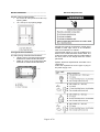
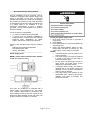
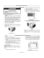
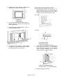
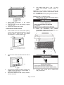
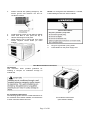
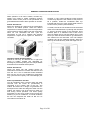
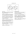
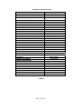
WINDOW
AIR CONDITIONER
INSTALLATION
AND
OPERATION
CATALOG NO.
WH12ZM
PRODUCT CODE
420-0074
950-0053-revA
11-09-06
Page 1 of 20
TABLE OF CONTENTS
AIR CONDITIONER SAFETY………………………………………………………………………………………….2
NORMAL CARE & MAINTENANCE………………………………………………………………………………….3
INSTALLATION REQUIREMENTS…………………………………………………………………………………..5
ELECTRICAL REQUIREMENTS……………………………………………………………………………………..6
INSTALLATION INSTRUCTIONS……………………………………………………………………………………8
THROUGH-THE-WALL CABINET INSTRUCTIONS-----------------------------------------------------------------------11
THRU-WALL INSTALLATION INSTRUCTIONS----------------------------------------------------------------------------13
GENERAL OPERATING INSTRUCTIONS…………………………………………………………………………16
TROUBLESHOOTING………………………………………………………………………………………………...18
SPECIFICATIONS……………………………………………………………………………………………………..19
WARRANTY………………………………………………………………………………………………………...….20
TECHNICAL SUPPORT
IF YOU NEED TECHNICQL SUPPORT, PLEASE CALL (705) 504-8590 BETWEEN THE HOURS OF 8:OO A.M.
TO 5:00 P.M. EST.
PLEASE HAVE YOUR EQUIPMENT MODEL NUMBER AND SERIAL NUMBER AVAILABLE WHEN YOU CALL.
AIR CONDITIONER SAFETY
Your safety and the safety of others are very important
We have provided many important safety messages in this manual and on your appliance.
Always read and follow all safety instructions.
This is the safety alert symbol.
This symbol alerts you to potential hazards that can kill or hurt you and others.
All safety messages will follow the safety alert symbol and word “DANGER”
Or “WARNING”
These words mean:
You can be seriously injured if instructions are not
followed.
Bodily injury or damage to personal property may
occur if instructions are not followed.
All safety messages will tell you what the potential hazard is, tell you how to reduce the
Chance of in jury, and tell you what can hap pen if the instructions are not followed.
Page 2 of 20
INSTALLATION
Complete step-by-step installation instructions are
furnished with your unit. These instructions will be
found on a separate page included with this manual
or in the mounting kit assembly. Follow these
instructions carefully. Keep these instructions with
this manual for future reference. Your unit will be one
of the following designs:
• Unit with a window mounting kit
These models are designed for mounting through an
opening in a wall. These units can be adapted to
window installation by using the optional window
mounting kit supplied with your unit.
Electrical Requirements
Grounding Instructions
This appliance is equipped with a three-prong
grounding plug for protection against possible shock
hazards. If a two-prong wall receptacle is
encountered, the customer is required to contact a
qualified electrician and have the two-prong wall
receptacle replaced with a properly grounded threeprong wall receptacle in accordance with the National
Electrical Code. Room air conditioners are designed
to operate according to the requirements on the
nameplate and as shown in Table 1.
Fuse or circuit breaker ratings must be according to
the fuse instruction label and as shown in Table 1. Do
not plug models marked “Use on Single Outlet Circuit
Only” into a circuit with another appliance or light
fixture.
Receptacle Wiring
Receptacle wiring must be of adequate size for unit.
Refer to unit identification plate for exact power
requirements.
Minimum size of wiring, based on power
requirements, is:
Units up to 20 amps: 12 gauge
20-30 amp units: 10 gauge
LCDI or AFCI Power Cords
Underwriters Laboratories (UL) and the National
Electric Code (NEC) now require power cords that
sense current leakage and can open the electrical
circuit to the unit. In the event the unit does not
operate, check the reset button located on or near
the head of the power cord as part of the normal
troubleshooting procedure.
Use copper wire only. The consumer’s responsibility
is to provide proper and adequate receptacle wiring
that conforms to all applicable codes. All wiring
should be installed by a qualified electrician.
• Unit without a window mounting kit
No window mounting kit is supplied with the unit.
These models are designed for mounting through an
opening in a wall. These units can be adapted to
window installation by purchasing an optional window
mounting kit. Consult your dealer to choose the kit
that is appropriate for your model and installation.
ROOM AIR CONDITIONER/HEATING UNITS
Heat model is by electric heating elements.
See specification sheet for electrical data information.
NORMAL CARE AND MAINTENANCE
Annual Inspection
It is suggested that your unit be inspected by your
dealer or contactor once a year. It is advisable to
have the outer case removed and the unit thoroughly
cleaned.
NOTE: The life of your unit may be greatly reduced if
you live in a salt air or other corrosive type
environment. Under these conditions, the unit should
be removed from its case and completely cleaned at
least once a year. At that time any scratches or
blisters on the painted surfaces should be sanded
and repainted. Placing an algaecide tablet in the
outdoor side of the unit’s base-pan is suggested in
humid areas where algae formation is common.
Page 3 of 20
Front Grill and Filter Removal
Fan Motor Care
The front contains an air filter that can be removed on
the left or right side of the front. To clean the filter use
the following method for filter removal:
The fan motor is permanently lubricated for long life.
There is no need to oil the motor.
Slide-out Chassis Removal from Outer Case
1. Remove two side Phillips screws attaching case
to chassis base-pan.
2. Remove two control knobs.
3. Remove two side Phillips screws attaching front
panel to case.
4. If the unit has a screw holding the base-pan clip
to the chassis, remove the screw.
5. Using base-pan handle, pull chassis straight out,
slowly and evenly, until approximately 9 – 12
inches extends from outer case. Use both hands
to grasp base-pan and pull remaining chassis
from outer case.
Grasp filter handle and slide filter out of unit.
NOTE: Base-pan clip is shipped in plastic bag with
mounting screw and condensate drain cup. Install clip
after reinserting chassis into outer case to prevent
accidental chassis removal.
Reinstall air filter by reversing removal procedure.
Front Grill and Cabinet Cleaning
Grill and cabinet may be cleaned with warm water
and mile soap or detergent. Cleaning and polishing
compounds are not recommended as they may
damage plastic surfaces.
Air Filter Cleaning
A dirty air filter reduces operating efficiency of unit.
Filter should be inspected at least once every week
during operation. Clean filter with vacuum cleaner or
wash in warm water and mild detergent. Filter should
be thoroughly dried before replacing in unit. Do not
operate unit without filter in place.
Page 4 of 20
IMPORTANT SAFETY INSTRUCTIONS
To reduce the risk of fire, electrical shock or injury when using your air conditioner,
follow these basic precautions:
• Plug into a grounded 3 prong outlet
• Do not use an extension cord.
• Do not remove ground prong.
• Unplug air conditioner when servicing
• Do not use an adapter
• Use two or more people to move and install
air conditioner.
WARNING:
________________________________________________________________________________________
INSTALLATION REQUIREMENTS
________________________________________________________________________________________
Tools and Parts
Gather the required tools and parts before
starting installation.
Read and follow the instructions provided with
any tools listed here.
Tools Needed
• Flat-blade and Phillips screwdriver
• Tape measure
• Drill and 3/16” or smaller bit
• Level
Through-the-wall installation:
In addition to the tools listed above, the following
tools are needed for through-the-wall installation:
• Saw
• Wood Preservative
• Caulk
• 1” (2.5cm) or thicker lumber
• 7 - #10 x 1” wood screws
Parts supplied (on some models)
Check that all parts are included in parts package
NOTE: Installation parts are supplied for doublehung windows up to 40” (101.6cm) wide.
Page 5 of 20
Location Requirements
IMPORTANT: observe all governing codes and
ordinances.
Check the location where air conditioner will be
installed. Proper installation is your responsibility.
Make sure you have everything necessary for
correct installation.
The location should provide:
• Grounded electrical outlet within 4 ft
(122cm) of where the power cord exits
the
air
conditioner.
Note: Do not use an extension cord.
• Free movement of air in room to be
cooled.
• A large enough opening for the air
conditioner.
• Adequate wall support for weight of air
conditioner. Air conditioner weighs
between 94 and 103 lbs (43 to 47kg).
NOTE: Cabinet louvers must not be obstructed.
Air must be able to pass freely through the
cabinet louvers.
_______________________________________
Window Installation
_______________________________________
Window opening measurements:
• 27” min to 38” max (68.6 cm to 95.5 cm)
opening width.
• 16 ¼ min (41.3 cm) opening height.
Electrical Requirements
_
______________________________________
Through-the-wall Installation
_______________________________________
The wall opening measurements should be:
• Height: 15 9/16” (39.5cm) plus twice the
thickness of wood used to build frame.
• Width: 22 13/16” (57.9 cm) plus twice the
thickness of wood used to build frame.
Page 6 of 20
Ground wire must be connected to ground screw
located in lower right corner of air conditioner
when air conditioner is in cabinet.
The electrical ratings for your air conditioner are
listed on the model and serial number label. The
model and serial number label is located behind
the front panel on the flange below the control
panel area.
Specific electrical requirements are listed in the
chart below.
Follow the requirements for the type of plug on
the power supply cord.
_______________________________________
Recommended grounding method
_______________________________________
This air conditioner must be grounded. This air
conditioner is equipped with a power supply cord
having a grounded 3 prong plug. To minimize
possible shock hazard, the cord must be plugged
into a mating, grounded 3 prong outlet, grounded
in accordance with all local codes and ordinances.
If a mating outlet is not available, it is the
customer’s responsibility to have a properly
grounded 3 prong outlet installed by a qualified
electrical installer.
It is the customer’s responsibility:
• To contact a qualified electrical installer
• To assure that the electrical installation is
adequate and in conformance with National
Electrical Code, ANSI/NFPA 70- latest
edition, and all local codes and ordinances.
Copies of the standards listed may be obtained
from:
National Fire Protection Association
One Batterymarch Park
Quincy, MA 02269
_______________________________________
Power Supply Cord
_______________________________________
NOTE: YOUR UNIT’S DEVICE MAY DIFFER
FROM THE ONES SHOWN.
This room air conditioner is equipped with a
power supply cord required by UL. This power
cord contains state-of-the-art electronics that
sense leakage current. If the cord is crushed, the
electronics detect leakage current and power will
be disconnected in a fraction of a second.
Page 7 of 20
To test your power supply cord:
1. Plug power supply cord into a grounded 3
prong outlet.
2. Press RESET
3. Press TEST (listen for click; Reset button will
trip and pop out).
4. Press and release RESET (listen for click;
Reset button will latch and remain in). The
power supply cord is ready for operation.
NOTES:
• The Reset button must be pushed in for
proper operation.
• The power supply cord must be replaced
if it fails to trip when the test button is
pressed or fails to reset.
• Do not use the power supply cord as an
off/on switch. The power supply cord is
designed as a protective device.
• A damaged power supply cord must be
replaced with a new power supply cord
obtained from the product manufacturer
and must not be repaired.
• The power supply cord contains no user
serviceable parts. Opening the tamperresistant case voids all warranty and
performance claims.
___________________________________________________________________________________________
INSTALLATION INSTRUCTIONS
___________________________________________________________________________________________
UNPACKING
3. Remove front panel by removing 2 Phillips
screws on both sides.
4. Remove both knobs from control panel.
5. Remove ground screw and ground wire from
front of air conditioner base. Save ground
screw.
Remove packaging materials.
• Remove and dispose or recycle all packaging
materials.
• Remove tape and glue residue from surfaces
before turning on the air conditioner. Rub a small
amount of liquid dish soap over the adhesive with
your fingers. Wipe with warm water and dry.
• Do not use sharp instruments, rubbing alcohol,
flammable fluids, or abrasive cleaners to remove
tape or glue. These products can damage the
surface of your air conditioner.
• Handle air conditioner gently.
6. Pull on handle to slide air conditioner out of
cabinet. Place air conditioner on cardboard.
1. Remove air conditioner from carton and place it
on cardboard.
2. Remove shipping screws from both sides of
cabinet.
NOTE: Do not lift, push, pull or remove any
expanded polystyrene (foam) from inside the air
conditioner. It is not packing material.
________________________________________________________________________________________
WINDOW INSTALLATION (on some models)
NOTES:
• Place top channel on top of air conditioner
• Handle air conditioner gently
cabinet, lining up the 3 holes in top channel
with 3 holes on top of air conditioner cabinet.
• Be sure your air conditioner cabinet does not
• Using 3 - #10 x 3/8” pan-head Phillips screws,
fall out of the opening during installation or
attach top channel to air conditioner cabinet.
removal.
• The location where the power cord exits the air
conditioner should be no more than 4 ft (122cm)
from a grounded 3 prong outlet.
• Do not block the louvers on the front panel.
• Do not block the louvers on the outside of the
air conditioner.
_________________________________________
Attach Top Channel
NOTE: Attach top channel and side curtains to air
conditioner cabinet before placing cabinet in
window.
•
Locate supplied bag of screws.
Page 8 of 20
Attach side curtains
1.
Locate provided bag of screws
2.
Insert top and then bottom of right-hand
curtain housing in top and bottom curtain guides on
air conditioner cabinet.
5.
Slide curtain housing into guides as far as it
will go.
6.
Repeat above steps for left-hand curtain.
_________________________________________
Attach Foam Adhesive Seal
Back View
Bottom View
3.
Extend right-hand curtain outward so you
may insert the first screw through the middle hole
of the curtain. Using #10 x ¼” pan-head Phillips
screw, screw curtain to middle hole in air
conditioner cabinet.
NOTE: This screw is required to correctly attach
curtain (top to bottom) to the air conditioner cabinet.
_________________________________________
Install Cabinet into Window
• Handle air conditioner gently.
• Be sure your air conditioner cabinet does not
fall out of the opening during installation or
removal.
• The location where the power cord exits the
air conditioner should be no more than 4 ft
(122cm) from a grounded 3 prong outlet.
• Do not block the louvers on the front panel.
• Do not block the louvers on the outside of the
air conditioner.
1. Center empty cabinet in window. Check that
lower rail of air conditioner cabinet is behind
and against back side of windowsill. Maintain
a firm hold on the air conditioner cabinet.
Lower window sash to hold cabinet in place.
Top channel must be on inside room of
window sash.
4.
While the right hand curtain is still extended,
insert #10 x ¼” pan-head Phillips screws into the
top and bottom slots of curtain. Screw Curtain to
the top and bottom holes in air conditioner cabinet.
NOTE: Some curtains may have 2 slots on each
end. You will be able to see a mounting hole
through the correct slot.
Page 9 of 20
2. Measure the distance between the right-hand
side of the cabinet and the inside of the
window channel
3. Repeat for left side. Adjust the cabinet until
the distance on each side is the same.
_______________________________________
Attach Side Curtains to Window Frame
1. Pull left-hand curtain out until it fits into
window channel. Use a 3/32” drill bit to drill a
starter hole through the hole in the curtain
housing and into the lower window sash.
Front View
4. Use a 3/16” drill bit to drill 3 starter holes ½”
deep through the 3 holes in the cabinet and
into the window sill.
5. Attach cabinet to windowsill with 3 - #10 x ½”
pan-head Phillips screws.
Top View
6. Check that the air conditioner cabinet is tilted
½ bubble on carpenters level to the outside
so that water will run to the outside.
2. Insert one of the #10 x ¾” round-head
screws through hole and into lower window
sash. Insert one of the #10 x ¾” round-head
screws through threaded hole in top of
curtain and one in bottom of curtain.
3. Repeat for right-hand curtain.
Page 10 of 20
Option 1 – Wood, metal or plastic molding
When you are using wood, metal or plastic
molding, the wood frame should line up with
inside wall as shown.
Complete Window Installation
1. Insert foam seal behind the top of the lower
window sash and against the glass of the
upper window.
2. Place window-lock bracket on top of lower
window and against upper window sash.
3. Use a 3/32” drill bit to drill a starter hole
through the hole in the bracket and into the
window sash.
4. Attach window-lock bracket to window sash
with #10 x ¾” round-head screw to secure
window in place.
Option 2 – Plastered wall with no molding
If the plastered wall is to be flush with the cabinet
and no molding is used, the wood frame must be
set ½” (13mm) into the inside wall.
_______________________________________
Through-the-wall Cabinet Installation
_______________________________________
NOTES:
• Handle air conditioner gently.
• Be sure your air conditioner cabinet does not
fall out of the opening during installation or
removal.
• The location where the power cord exits the
air conditioner should be no more than 4 ft
(122cm) from a grounded 3 prong outlet.
• Do not block the louvers on the front panel.
• Do not block the louvers on the outside of the
air conditioner.
• It is the customer’s responsibility and
obligation to have this product installed by a
qualified technician familiar with through-thewall room air conditioner installations.
Install Wood Frame
1. Construct wood frame. See “Location
Requirements” for dimensions.
2. Measure outside width and height of frame to
determine wall opening dimensions.
3. Cut opening through the wall. Remove and
save insulation.
NOTES:
• Dimension for depth depends on wall
thickness and type of molding.
• Do not block louvers in air conditioner
cabinet.
• Use 1” (2.5cm) or thicker lumber for wood
frame.
Page 11 of 20
5.
use existing holes and 6 - #10 x 1” wood
screws (not provided) to attach cabinet to
frame.
NOTE: Do not over-tighten screws or cabinet will
distort and provide a poor air seal between cabinet
and air conditioner.
6.
Caulk all outside wall openings around cabinet.
NOTE: Handle air conditioner gently.
1.
Make sure the free end of the ground wire is
outside of the cabinet.
4. Apply wood preservative to the outside
exposed surface.
5. Insert the frame in the wall opening. Square
and level frame.
6. Attach frame securely to the wall.
Install Cabinet into Wood Frame
1.
Insert cabinet into the framed wall opening.
The top of the cabinet should extend ½” (13mm)
into the room. If there is trim, the cabinet
should extend ½” (13mm) past the trim.
2.
Use a level to check that cabinet is level side to
side.
3.
Check that air conditioner cabinet is tilted to the
outside so that water will run to the outside. ½
bubble on carpenter’s level.
Reuse the insulation to seal opening between
cabinet and frame.
4.
2.
Insert
air
conditioner
into
cabinet.
REMEMBER: make sure the free end of the
ground wire is outside of the cabinet.
3.
Connect green ground wire to cabinet base
with ground screw.
Page 12 of 20
4.
Position Ground wire pointing straight up. Put
excess ground wire between coil and air
conditioner cabinet.
5.
6.
Install shipping screws on both sides of cabinet.
Insert front tabs of front panel into top of
cabinet and swing front into place.
Attach bottom front of panel with front panel
screws. Replace control knobs (on some
models).
7.
NOTE: For through-the-wall installations, if needed,
install molding around room side of cabinet.
8.
9.
Plug into a grounded 3 prong outlet.
Press RESET on the power supply cord.
___________________________________________________________________________________________
Thru-Wall Installation Instructions
Introduction
This instruction sheet provides guidelines for
installing a compact air conditioner through an
outside wall.
Air Conditioner Dimensions
The following figures show the outside dimensions of
air conditioner with chassis installed, and dimensions
of outer case with chassis removed.
Page 13 of 20
Air Conditioner Dimensions
(with chassis installed)
Dimensions of finished opening
Outer Case Dimensions
(chassis removed)
General Instructions
All compact room Air conditioners feature a slide-out
chassis. Chassis and front cover must be removed
from outer case for installation.
Masonry Construction
See CAUTION under General instructions. In
masonry walls, cut or build a finished opening 15
9/16 inches high by 22 13/16 inches wide. When
case is properly positioned in opening, secure it in
place with mortar or concrete nails driven through
holes in sides of outer case (shim case and pre-drill
holes before securing with nails).
Brick Veneer or Frame wall Construction
See CAUTION under General instructions. Cut or
build rough opening large enough to allow a framed,
finished opening 15 9/16 inches high and 22 13/16
inches wide. When case is properly positioned in
opening, secure it to framing material with nails or
screws driven through holes in sides of outer case
(shim case and pre-drill holes before securing).
A finished opening 22-13/16” wide x 15 9/16” high is
recommended. The lower left inside corner of
opening must be within 5 feet of an appropriate
electrical outlet. (see Use and Care manual for
electrical requirements).
When wall thickness exceeds 8-1/2 inches, opening
must be modified to allow air to enter side louvers on
case (see special instructions on back). Do not install
air conditioner in walls thicker than 11-3/4”.
Framed/Finished Opening
(brick veneer or frame wall construction)
Page 14 of 20
Placement of Outer Case in Opening
Place outer case in opening, flush against one side of
opening. Use carpenter’s level and ensure case is
level from side to side and has a 3/8 inch slope from
front to back (back of case must be 3/9 inch lower
than front to ensure proper condensate drainage). If
needed, use shims to level case (from side to side)
and to obtain proper back slope.
Installation in Wall Thicker than 8 – ½ Inches
The side louvers in outer case provide ventilation to
air conditioner compressor and fan motor and must
not be blocked. When installing unit in a wall over 9
3/8” thick, provisions must be made in wall opening to
ensure free air flow to the side louvers. This can be
accomplished by chamfering the vertical portions of
the outside opening as shown.
Front of case must project ¾ inch (minimum) beyond
inside wall in order to attach air conditioner front
frame. If framing indoor side of opening with wood
molding (or other decorative material), extend outer
case ¾ inch beyond molding.
Ventilation louvers on top of case must not be
obstructed. Do not attempt to install unit in walls
thicker than 11-3/4 inches.
When case is properly positioned in opening, use
wood shims to fill any gaps between case and
finished opening, especially in area where case will
be secured to opening. Take care not to warp or
distort case when installing shims. For condensate
drainage, install drainage cup in drain hoe on baseplate of case.
Installed Case
(brick veneer or frame wall construction shown)
Page 15 of 20
GENERAL OPERATING INSTRUCTIONS
___________________________________________________________________________________________
While operation of all units is similar, controls vary
slightly from model to model. Operating Controls
section shows control panel of unit purchased and
gives detailed information about operation of controls.
Airflow Around Unit
Select the highest fan speed and set temperature
control to its coldest position. When the desired
temperature is reached, slowly move the temperature
control toward a warmer setting until the compressor
shuts off. The thermostat will then cycle the
compressor on and off to maintain this selected
temperature. Adjust the fan speed for desired air
circulation.
However, in very humid conditions excess amounts
of water may drip off the unit chassis. If this proves to
be a problem, install the condensate drain cup
included with the unit to route excess water where it
would not be a problem (see illustration).
To install, remove the unit chassis from the outercase.
Insert the condensate drain cup through the recessed
½” hole on the back center of the outercase. Once
inserted, place a ½” diameter hose or tube on the
drain cup bottom spout. The hose allows you to route
where you want the excess water to go. Reinsert the
unit chassis into the outercase. The unit basepan
overflow hole will be positioned directly above the
drain cup and will catch any water that might run out.
Changing airflow Direction Baffles
Airflow on unit may be diverted left or right from
center by baffles. Upward and downward air
discharge is provided by tilting louvers. Adjust baffles
and tilt louvers for desired airflow pattern.
Airflow Around Unit
Check the indoor grill and outdoor louvers for
obstructions to airflow. Do not block the airflow to and
from the unit. If air is obstructed and/or deflected
back into the unit, the air conditioner’s compressor
may cycle off and on rapidly. This could damage your
unit.
Drain Cup Installation and Use
Your air conditioner uses a system where the water
removed from the indoor air (condensate) is
channeled to the outdoor side of the unit. The
outdoor fan blade has a “slinger” ring attached to it
that dips into the water and slings the water onto the
outdoor coil surface. This is the sound of water you
hear during normal operation. The water quickly
evaporates on this warm surface and improves the
efficiency of your air conditioner. In normal conditions
the unit can evaporate the water as fast as it is
removed from the indoor air.
Page 16 of 20
Operating Controls
Fan Control
OFF
Completely shuts off the unit. To prevent
blowing fuses, wait two minutes after turning the unit
off before turning it on again.
LOW COOL
Filters and circulates room air with
the fan running continuously on low speed. Also
cools and dehumidifies while the compressor is
running. Select this setting for quiet cooling operation.
HIGH COOL
Filters and circulates room air with
the fan running continuously on high speed. Also
cools and dehumidifies while the compressor is
running. Select this setting for maximum air
circulation and cooling effect.
LOW HEAT
Filters and circulates room air with
the fan running continuously on low speed. Also
heats while the compressor or electric heat is running.
Select this setting for quiet heating operation.
Temperature Control
Turn this control to the left for a warmer room
temperature, to the right for a cooler temperature.
Vent Control (On Some Models)
Choose one of the following two settings by sliding
the vent control under the appropriate marking:
EXHAUST
Exhausts room air to the outdoors.
Also circulates and filters room air. This position can
be used to exhaust stale or smoky air. To conserve
energy, it is advised that the Fan Control be in the
Fan Only setting when using this feature.
CLOSED
Exhaust damper is closed. Unit
circulates and filters room air. This position should be
used for normal cooling operation.
HIGH HEAT
Filters and circulates room air with
the fan running continuously on high speed. Also
heats while the compressor or electric heater is
running. Select this setting for maximum air
circulation and heating effect.
FAN ONLY
Select this setting for circulating or
exhausting room air without cooling.
Page 17 of 20
TROUBLESHOOTING
The following is a list of problems that are sometimes encountered when using a room air conditioner.
Possible cause and suggested remedies are given for each problem.
• UNIT WILL NOT RUN
Push reset button on power cord.
Set Fan control to position other than OFF.
Make sure plug is firmly seated in outlet.
Check for blown fuses, tripped circuit breakers.
•
LITTLE OR NO COOLING OR HEATING,
(Fan and Compressor run)
Set vent to CLOSED
Remove obstruction from indoor grill or outdoor
louvers.
Dirty air filter. Clean or replace as needed.
Check with dealer to determine proper capacity
unit for application.
•
LITTLE OR NO COOLING OR HEATING,
(only fan runs)
For cooling, turn Temperature Control to cooler
setting.
For heating, turn Temperature Control to warmer
setting.
• NOISY UNIT
Tighten any loose parts
Provide additional support for unit.
Normal in high humidity. Stop noise by removing
drain plug or adding condensate drain cup.
Check with dealer to determine proper capacity
unit for application.
Page 18 of 20
• MOUNTING SUPPORT NOT INSTALLED
Some models require removal of storm window
frame before installation.
• FROST ON INDOOR COIL
Clean air filter by vacuuming or washing with
water and mild soap.
Turning Temperature Control to warmer setting
reduces occurrence and duration of frost.
• ODORS IN COOLING
To reduce algae growth, use an algaecide tablet
in base pan; remove drain plug; add condensate
drain cup and hose.
Thoroughly clean unit.
• ODORS IN HEATING
Caused by dust accumulation during unused
months. Odor dissipates quickly with heater use.
TECHNICAL SPECIFICATIONS
MODEL
BTU COOLING
BTU HEATING
EER RATING
WH12ZM
11600 – 11200
10700 – 8500
9.8
DEHUMIDIFICATION (pints/hour)
AIRFLOW (CFM)
VOLTAGE
FREQUENCY
AMPS COOLING
AMPS HEATING
WATTS COOLING
WATTS HEATING
PLUG TYPE
POWER CORD RATING (amps)
POWER CORD TYPE
POWER CORD LENGTH
REFRIGERANT
REFRIGERANT CHARGE (oz. / lbs)
SOUND (INSIDE/OUTSIDE) dba (MAX)
4 WAY AIR ADJUSTMENT
2 WAY AIR SWING
AIR DISCHARGE
MOTOR TYPE
MOTOR CAPACITOR
CONTROLS
THERMOSTAT TEMP ºF
CABINET SIZE (INCHES)
WIDTH
DEPTH
HEIGHT
WINDOW OPENING
THRU WALL MAX THICKNESS
WEIGHT / lbs (GROSS/NET)
APPROVALS
TABLE 1
Page 19 of 20
2.6
310 (MAX)
230 - 208 VAC
60 HZ
5.2 – 5.7
14.84 – 13.42
1164 – 1133
3500
Type B
20
LCDI
6’
R22
32.32 / 2.02
58 / 62
YES
YES
TOP
BALL BEARING
4 µfd
MECHANICAL
61ºF to 89ºF
11 ½”
23 ½”
15 ⅜”
28” – 44”
5½
114 / 97
UL/ CUL
WARRANTY
International Refrigeration Products warrants that the product supplied is free from defects in
material and workmanship. This warranty is valid as long as this product is properly handled,
installed, operated and serviced in accordance with the Installation and Operating Instructions
shipped with this unit, and the warranty card is completed and mailed no later than 30 days after
date of purchase. All warranty claims must be made within one (1) year (five (5) years for
compressor) from date of purchase (unless national regulations require a longer registration
period).
This warranty provides free replacement of defective parts only. Labor and replacement parts as
a result of normal wear and tear are not covered under this warranty.
Additional claims are excluded, unless required by national regulations. International
Refrigeration Products Inc. is not responsible for incidental, consequential, direct, or indirect
damages or expenses relating to the use of, or the inability to use the product for any purpose.
Other implied warranties are excluded.
This constitutes International Refrigeration Products warranty obligation and replaces any and
all prior warranties for this product.
INTERNATIONAL REFRIGERATION PRODUCTS INC.
11325 Nations Ford Rd., Charlotte, NC 28134-8393
(704) 504-8590 Phone (704) 504-3023 Fax
Copyright 2006 IRP Inc.
950-0053
Page 20 of 20