1
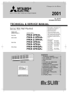
SPLIT-TYPE, HEAT PUMP AIR CONDITIONERS
No. OC153
TECHNICAL & SERVICE MANUAL
Series PEH Ceiling Concealed
Indoor unit
[Models]
PEH-2.5EKHA
PEH-3EKHA
PEH-4EKHSA
PEH-5EKHSA
[Service Ref.]
PEH-2.5EKHA2.TH
PEH-3EKHA2.TH
PEH-4EKHSA2.TH
PEH-5EKHSA2.TH
This manual does not cover the following
outdoor units. When servicing them,
please refer to the service manual
No.OC128,150 and this manual in a set.
[Service Ref.]
PUH-2.5VKA2
PUH-3VKA2,3YKA2
PUH-4YKSA3
PUH-5YKSA3
PUH-2.5VKA2.UK
PUH-3VKA2.UK
PUH-3YKA2.UK
PUH-4YKSA2.UK
PUH-5YKSA2.UK
CONTENTS
Indoor unit
FILTER
CHECK MODE
TEST RUN
1. FEATURES ···········································2
2. PART NAMES AND FUNCTIONS ········3
3. SPECIFICATIONS·································6
4. DATA ·····················································8
5. OUTLINES AND DIMENSIONS··········14
6. WIRING DIAGRAM·····························18
7. REFRIGERANT SYSTEM DIAGRAM ······19
8. OPERATION FLOW-CHART ··············20
9. MICROPROCESSOR CONTROL·······24
10. TROUBLESHOOTING ························41
11. DISASSEMBLY PROCEDURE ···········49
12. PARTS LIST········································51
13. OPTIONAL PARTS ·····························55
The Slim Line.
From Mitsubishi Electric.
Remote controller
1
FEATURES
Series PEH Ceiling Concealed
FILTER
CHECK MODE
TEST RUN
Indoor unit
Remote controller
Outdoor unit
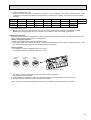
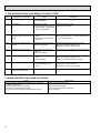
Cooling capacity / Heating capacity (with Heater)
Service Ref.
W
Btu / h
PEH-2.5EKHA2.TH
6,400/6,700 (8,800)
21,800/22,900 (30,000)
PEH-3EKHA2.TH
7,700/8,300 (10,400)
26,300/28,300 (35,500)
PEH-4EKHSA2.TH
9,700/10,400(12,800)
33,100/35,500 (43,700)
PEH-5EKHSA2.TH
12,400/13,000(16,000)
42,300/44,400 (54,600)
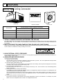
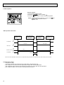
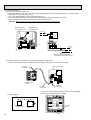
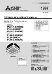
1. TOTALLY INVISIBLE INDOOR UNIT BEHIND THE CEILING
The totally hidden indoor unit that lies above the ceiling surface enables you to utilize full floor space while allowing for flexible interior design. This new feature is recommended for stores and offices where the user´s own image is allowed to be
incorporated.
2. MOST SUITABLE FOR SIMULTANEOUS TWO ROOMS AIR CONDITIONING
Using air ducts for cooling / heating airflow that matches with the structure and purpose of the room enables you to provide
two air outlets for simultaneous cooling / heating of two rooms.
Air outlet duct
air outlet
air outlet
Air intake duct
air intake
3. HIGH EXTERNAL STATIC PRESSURE
The acceptable external static pressure of 127Pa (12.7mmAq) allows long ducts to be used more extensively to achieve convenient location of indoor units.
4. ADVANCED MICROPROCESSOR
(1) Easy to use microprocessor
1) Ultra-thin remote controller
The streamlined, square controller is designed to blend well with any interior. Also, the sophisticated microprocessor
allows you to easily carry out a wide range of operations.
2) Attractive liquid crystal display (LCD)
The unit´s operation mode, set temperature, room temperature, timer setting, and fan speed are displayed on the remote
controller´s easy-to-read Liquid Crystal Display (LCD).
3) Convenient 24-hour ON-OFF timer
The timer switches Mr. SLIM on and off automatically at the time you set. Once the timer is set, the remaining time is
shown on the LCD.
4) Self-diagnostic feature indicates faults instantly
If a problem occurs, the unit will stop operating and the set temperature indicator will change to a self-diagnostic indicator, which shows the location of the trouble.
If the check switch is pressed twice, the unit stops operating and the check mode is initiated. The location of the most
recent problem that was stored in the memory is displayed on the LCD. This is extremely useful for maintenance purposes.
5) Useful memory feature for storing instructions
The previous set value is memorized so that constant temperature control can be achieved. For example, if a power
failure occurs, the temperature will not have to be readjusted afterwards.
2
(2) Non- polar two-wire remote controller cable
The slim, non-polar, two-wire remote controller cable makes installation simple and troublefree. Also, the remote controller wire can be extended up to 500m.
(3)Automatic cooling / heating changeover operation
An automatic cooling and heating changeover operation system allows you to easily control comfortable year-round air
conditioning.
Once the desired temperature is set, unit operation switches automatically between cooling and heating, in accordance
with the room temperature. In addition, the use of an outdoor unit fan speed controller allows cooling even when outdoor temperatures are as low as -5 °C.
5. INNOVATIVE MICROPROCESSOR CONTROL SYSTEM
The most significant feature of PEH-EKH(S)A series is the advanced microprocessor control. The development of this system is due to the recent world-wide trend in the air conditioning of larger buildings. They are moving away form centralized
duct systems to using individual split type units instead. There are a number of reasons for this change. First of all, the duct
´s costly and troublesome installation is eliminated. Second, the overall air conditioning balance is excellent in split type units.
Lastly, the operation costs are low due to the flexible control of each unit. This system was developed exclusively by
Mitsubishi Electric because of high demand. The microprocessor control makes individual control, group control, control
using two remote controllers, remote on / off control and individual control possible without troublesome equipment modifications.
2
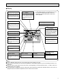
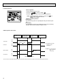
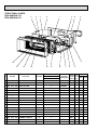
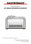
PART NAMES AND FUNCTIONS
● Indoor (Main) Unit
Air intake duct flange
Air intake
(sucks the air inside the room into the unit)
Air outlet
Air outlet duct flange
3
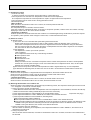
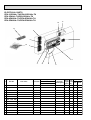
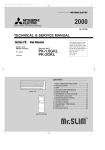
● Remote controller
● Once the operation of the unit is
set, subsequent operations can
only be performed by pressing
the ON/OFF button repeately.
● Operation buttons
w button
q button
This switches between
continuous operation and
the timer operation.
l button
This sets of switches the
current time. start time and
stop time.
This sets the ventilation fan
speed.
ON/OFF button
a button
This switches between the
operation and stop modes
each time it is pressed. The
lamp on this butoon lights
during operation.
Press this button to switch
the cooler electronic dry
(dehumidify) automatic and
heater modes.
FILTER
CHECK MODE
TEST RUN
i TEMP button
button
This adjusts the vertical
angle of the ventilation.
(This button does not operate in this model)
This sets the room temparature. The temparature
setting can be performed in
1°C units
Setting range
Cooler 19°C to 30°C
Heater 17°C to 28°C
050
This model name of the
remote controller is indicated.
FILTER button
This resets the filter service
indication display.
(This button does not operate in this model)
k button
This switches the horizontal fan motion ON and OFF.
(This button does not operate in this model)
4
CHECK-TEST RUN button
Only press this button to
perform an inspection
check or test operation. Do
not use it for nomal operation.
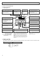
● Display
CENTRALLY
CONTROLLED display
This indicates when the unit is controlled by optional features such as
central control type remote controller.
r display
The current time , start time and stop
time can be displayed in tensecond
intervals by pressing the time switch
button. The start time or stop time is
always displayed during the timer
operation.
In this display example on the bottom left, a condition where all display lamps light is shown for
explanation purposes although this differs from
actual operation.
w display
l display
This indicates when the continous
operation and time operation modes
are set.
It also display the time for the timer
operation at the same time as when
it is set.
The selected fan speed is displayed.
—88°C display
OPERATION MODE display
FILTER
CHECK MODE
This indicates the operation mode.
TEST RUN
Operation lamp
STANDBY display
This indicates when the standby
mode is set from the time the sleep
operation starts until the heating air
is discharged.
The temperature of the suction air is
displayed during operation. The display range is 8° to 39°C. The display
flashes 8°C when the actual temperature is less than 8° and flashes
39°C when the actual temperature is
greater than 39°C.
This lamp lights during operation,
goes off when the unit stops and
flashes when amalfunction occurs.
050
DEFROST display
This indicates when the defrost operation is performed.
CHECK MODE
CHECK display
This indicates when a malfunction
has occurred in the unit which should
be checked.
—88°C display
This displays the selected setting
temperature.
/ display
This lamp lights when electricity is
supplied to the unit.
TEST RUN
display
This display lights in the check mode
or when a test operation is performed.
Caution
● Only the display lights when the unit is stopped and power supplied to the unit.
● When power is turned ON for the first time the (CENTRAL CTRL) display appears to go off momentarily but this is not a
malfunction.
● When the central control remote control unit, which is sold separately, is used the ON-OFF button, a button and
i TEMP button do not operate.
● “NOT AVAILABLE” is displayed when the k button and j button are pressed.This indicates that this room unit is not
equipped with the fan direction adjustment function and the louver function.
5
3
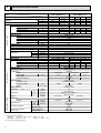
SPECIFICATIONS
Item
Service Ref.
Function
PEH-2.5EKHA2 .TH
PEH-3EKHA2 .TH
Heating
Cooling Heating Cooling Heating
Cooling
22,900
28,300
28,300
26,300 (35,500) 26,300 (35,500)
21,800
(30,000)
Capacity
w1
6,700
8,300
8,300
7,700 (10,400) 7,700 (10,400)
6,400
(8,800)
2.62
3.33
3.33
Total input
3.54 (5.43) 3.54 (5.43)
2.85
(4.72)
PEH-2.5EKHA2 .TH
PEH-3EKHA2 .TH
Service Ref.
Single, 50Hz, 220-240V
Single, 50Hz, 220-240V
Power supply(phase, cycle,voltage)
0.39
0.39(2.49)
0.39 0.39(2.49) 0.39 0.39(2.49)
Input
kW
1.66
1.66(10.41)
1.66 1.66(10.41) 1.66 1.66(10.41)
Running current
A
2.30
2.30(11.1)
2.30 2.30(11.1) 2.30 2.30(11.0)
Starting current
A
Galvanized sheets
External finish
Plate fin coil
Heat exchanger
Centrifugal (direct)
Fan(drive) o No.
0.23
Fan motor output
kW
22-27<780-950>
Airflow(Low-High)
K/min,<CFM>
127 (12.7) at Hi-notch
External static pressure
Pa(mmAq)
2.1
Booster heater
kW
Remote control & built-in
Operation control & Thermostat
52 - 55
Noise level(Low-High) w2
dB(A)
32 <1-1/4>
Cond. drain connection O.D.
mm,(in)
785 <31>
mm,(in)
W
690 <27-1/6>
Dimensions
mm,(in)
D
428 <16-7/8>
mm,(in)
H
47<104>
48<106>
Weight
kg,(lbs)
PUH-3VKA2 (.UK) PUH-3YKA2 (.UK)
PUH-2.5VKA2 (.UK)
Service Ref.
Single, 50Hz, 220-240V 3,50Hz, 380-415V (4wires)
Single, 50Hz, 220-240V
Power supply (phase, cycle, voltage)
2.46
2.23
3.15
2.94
3.15
2.94
Input
kW
10.68
9.78
13.82 12.89 5.16
4.81
Running current
A
52
52
58
58
37
37
Starting current
A
External finish
Munsell 5Y 7/1
Refrigerant control
Capillary tube
Compressor
Hermetic
NH52YDA
NH41VMD
NH52VND
Model
2.4
2.0
2.2
Motor output
kW
Starter type
Line start
Thermal relay, Thermal switch,
Protection devices
Internal thermostat,HP switch Internal thermostat,HP switch HP
switch,Anti-phase protector.
Plate fin coil
Heat exchanger
Propeller (direct)o1
Fan(drive) o No.
Fan motor output
kW
0.085
0.085
Airflow
K/min,<CFM>
50<1.764>
Defrost method
Reverse cycle
Noise level
w2
dB(A)
52
W
mm,(in)
870 <32-1/4>
D
Dimensions
mm,(in)
295+24 <11-5/8 add 1>
H
mm,(in)
850 <33-7/16>
Weight
kg,(lbs)
68 <150>
75 <165>
Refrigerant
R-22
Charge
kg,(lbs)
2.8 <6.2>
3.2 <7.1>
Liquid
9.52 <3/8>
mm,(in)
Pipe size O.D.
Gas
15.88 <5/8>
mm,(in)
Indoor side
Flared
Connection method
Outdoor side
Flared
Height difference
Between the indoor &
Max. 50m
Piping length
outdoor unit
Max. 50m
REFRIGERANT PIPING
OUTDOOR UNIT
INDOOR UNIT
Btu/h
W
kW
w1 Rating condition <JIS B 8616>
(INDOOR)
Cooling : 27: D.B.,19:W.B.
(OUTDOOR) Cooling : 35: D.B.
w2 Noise level : Sound pressure level
6
Heating : 20: D.B.
Heating : 7: D.B.,6: W.B.
Item
Service Ref.
PEH-4EKHSA2.TH
PEH-5EKHSA2.TH
Heating
Cooling
Cooling
Heating
35,500
44,400
33,100
42,300
(43,700)
(54,600)
Capacity
w1
10,400
13,000
9,700
12,400
(12,800)
(16,000)
3.63
4.81
3.64
4.86
Total input
(6.03)
(7.81)
PEH-4EKHSA2.TH
PEH-5EKHSA2.TH
Service Ref.
Single, 50Hz, 220-240V
Power supply(phase, cycle,voltage)
0.44
0.44(2.84)
0.65
0.65(3.65)
Input
kW
1.87(11.87)
2.76
2.76(15.20)
1.87
Running current
A
2.60(12.6)
3.20
3.20(15.7)
2.60
Starting current
A
Galvanized sheets
External finish
Plate fin coil
Heat exchanger
Centrifugal (direct) o2
Fan(drive) o No.
0.24
0.28
Fan motor output
kW
27-34(950-1200)
34-42(1200-1480)
Airflow(Low-High)
K/min,<CFM>
127 (12.7) at Hi-notch
External static pressure
Pa(mmAq)
(3.0)
(2.4)
Booster heater
kW
Remote control & built-in
Operation control & Thermostat
54 - 58
Noise level(Low-High) w2
dB(A)
32 <1-1/4>
Cond. drain connection O.D.
mm,(in)
1055<41-1/2>
1255<49-7/16>
mm,(in)
W
690 <27-1/6>
Dimensions
mm,(in)
D
428 <16-7/8>
mm,(in)
H
61<134>
75<165>
Weight
kg,(lbs)
PUH-5YKSA3(2.UK)
PUH-4YKSA3 (2.UK)
Service Ref.
3,50Hz,380-415V(4wires)
Power supply (phase, cycle, voltage)
4.16
4.21
3.19
3.20
Input
kW
6.81
6.89
5.22
5.24
Running current
A
53
53
40
40
Starting current
A
External finish
Musell 5Y 7/1
Refrigerant control
Capillary tube
Compressor
Hermetic
NH56YDA
ZR61K3-TFD
Model
2.7
3.5
Motor output
kW
Starter type
Line start
Protection devices
Thermal relay, Thermal switch,HP switch, Anti-phase protector Internal thermostat,Thermal switch,HP switch, Anti-phase protector
Heat exchanger
Plate fin coil
Fan(drive) o No.
Propeller(direct)o2
Fan motor output
kW
0.065+0.065
0.085+0.085
Airflow
K/min,<CFM>
95<3.350>
Defrost method
Reverse cycle
Noise level
w2
54
55
dB(A)
W
870<34-1/4>
970<38-3/16>
mm,(in)
D
Dimensions
295+24<11-5/8 add 1>
345+24<13-9/16 add 1>
mm,(in)
H
mm,(in)
1,258 <49-1/2>
Weight
94<207>
114<251>
kg,(lbs)
Refrigerant
R-22
Charge
4.2<9.27>
5.4<11.9>
kg,(lbs)
Liquid
9.52 <3/8>
mm,(in)
Pipe size O.D.
Gas
19.5 <3/4>
mm,(in)
Indoor side
Flared
Connection method
Outdoor side
Flared
Height difference
Between the indoor &
Max. 50m
Piping length
outdoor unit
Max. 50m
Function
REFRIGERANT PIPING
OUTDOOR UNIT
INDOOR UNIT
Btu/h
W
kW
w1 Rating condition <JIS B 8616>
(INDOOR)
Cooling : 27: D.B.,19:W.B. Heating : 21: D.B.
Heating : 7: D.B.,6: W.B.
(OUTDOOR) Cooling : 35: D.B.
w2 Noise level : Sound pressure level
7
4
DATA
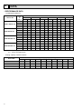
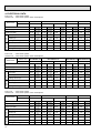
1 PERFORMANCE DATA
1) COOLING CAPACITY
Service Ref.
PEH-2.5EKHA2.TH
PEH-3EKHA2.TH
Indoor
Intake
air
W.B.°C
Outdoor intake air D.B.°C
CA
PEH-5EKHSA2.TH
CA
CA
P.C.
P.C.
CA
P.C.
CA
P.C.
CA
P.C.
16
6,457 2.28
6,280 2.38
6,049 2.56
5,804 2.75
5,545 2.93
5,271 3.12
18
6,875 2.33
6,694 2.43
6,450 2.62
6,194 2.82
5,926 3.01
5,646 3.20
20
7,297 2.37
7,126 2.48
6,871 2.68
6,606 2.88
6,330 3.09
6,043 3.30
22
7,724 2.42
7,576 2.53
7,314 2.74
7,040 2.95
6,756 3.18
6,461 3.41
16
7,768 2.84
7,555 2.96
7,278 3.19
6,983 3.41
6,671 3.64
6,342 3.88
18
8,271 2.89
8,053 3.02
7,760 3.26
7,452 3.50
7,130 3.74
6,793 3.98
20
8,779 2.95
8,573 3.08
8,267 3.33
7,948 3.58
7,616 3.84
7,270 4.10
22
9,293 3.00
9,115 3.14
8,799 3.40
8,470 3.67
8,128 3.95
7,773 4.23
9,786 2.92
9,518 3.04
9,168 3.28
8,797 3.51
8,426 3.75
8,018 3.98
18
10,419 2.98 10,145 3.10
9,775 3.35
9,388 3.60
8,994 3.84
8,577 4.09
20
11,060 3.03 10,800 3.17 10,414 3.42 10,012 3.68
9,596 3.94
9,168 4.21
22
11,707 3.09
11,085 3.50 10,670 3.77 10,230 4.06
9,791 4.35
16
12,510 3.90 12,167 4.06
18
13,319 3.97 12,969 4.14 12,496 4.47 12,001 4.80
20
14,138 4.05 13,806 4.23 13,313 4.57 12,799 4.92 12,266 5.27
22
14,965 4.12 14,679 4.31 14,170 4.67 13,640 5.04 13,078 5.41 12,516 5.81
16
PEH-4EKHSA2.TH
P.C.
45
40
35
30
25
20
11,482 3.23
11,720 4.37
11,245 4.69 10,771 5.00 10,249 5.32
11,497 5.13 10,964 5.46
11,720 5.62
Note CA : Capacity (W)
P.C. : Power consumption (kW)
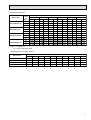
Cooling capacity correction factors
Service Ref.
8
Refrigerant piping length (one way)
5m
10m
15m
20m
25m
30m
35m
40m
45m
50m
PEH-2.5EKHA2.TH
1.00
0.989
0.980
0.970
0.960
0.950
0.940
0.930
0.920
0.910
PEH-3EKHA2.TH
1.00
0.981
0.968
0.952
0.940
0.925
0.913
0.900
0.886
0.874
PEH-4EKHSA2.TH
1.00
0.989
0.980
0.970
0.960
0.950
0.940
0.930
0.920
0.910
PEH-5EKHSA2.TH
1.00
0.981
0.968
0.952
0.940
0.925
0.913
0.900
0.886
0.874
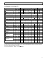
2) HEATING CAPACITY
Service Ref.
PEH-2.5EKHA2.TH
PEH-3EKHA2.TH
PEH-4EKHSA2.TH
PEH-5EKHSA2.TH
Indoor
Intake
air
W.B.°C
Outdoor intake air D.B.°C
CA
P.C.
CA
P.C.
CA
P.C.
CA
15
10
5
0
-5
-10
P.C.
CA
P.C.
CA
P.C.
15
4,588 1.79
5,259 1.98
5,994 2.18
6,792 2.39
7,653 2.61
8,576 2.85
20
4,393 1.93
5,052 2.13
5,768 2.34
6,539 2.57
7,366 2.81
8,247 3.07
25
4,222 2.04
4,847 2.27
5,539 2.51
6,297 2.75
7,121 3.02
8,011 3.29
15
5,684 2.27
6,514 2.51
7,425 2.76
8,414 3.03
9,481 3.32 10,624 3.62
20
5,443 2.45
6,259 2.71
7,145 2.98
8,101 3.27
9,125 3.58 10,217 3.90
25
5,230 2.60
6,004 2.88
6,861 3.19
7,801 3.50
8,822 3.83
15
7,122 2.48
8,163 2.74
9,303 3.01 10,543 3.31
11,880 3.62 13,312 3.95
20
6,820 2.67
7,842 2.95
8,953 3.25 10,150 3.56
11,434 3.90 12,802 4.25
25
6,554 2.83
7,524 3.14
9,774 3.82
11,054 4.18 12,435 4.56
15
8,903 3.28 10,203 3.63
11,629 3.99 13,179 4.38 14,850 4.80 16,640 5.23
20
8,524 3.54
9,803 3.91
11,191 4.30 12,688 4.72 14,292 5.16 16,002 5.63
25
8,192 3.75
9,404 4.17 10,747 4.60 12,218 5.06 13,817 5.54 15,544 6.04
8,597 3.47
9,924 4.18
Note CA :Capacity (W)
P.C. :Power consumption (kW)
Heating capacity correction factors
Service Ref.
Refrigerant piping length (one way)
5m
10m
15m
20m
25m
30m
35m
40m
45m
50m
PEH-2.5EKHA2.TH
1.00
1.00
1.00
1.00
1.00
1.00
0.998
0.995
0.993
0.990
PEH-3EKHA2.TH
1.00
1.00
1.00
1.00
1.00
1.00
0.998
0.995
0.993
0.990
PEH-4EKHSA2.TH
1.00
1.00
1.00
1.00
1.00
1.00
0.998
0.995
0.993
0.990
PEH-5EKHSA2.TH
1.00
1.00
1.00
1.00
1.00
1.00
0.998
0.995
0.993
0.990
9
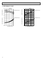
2. PERFORMANCE CURVE
Cooling
Heating
1.4
1.2
1.0
22
20
18
16
0.8
TOTAL INPUT (RATIO)
1.2
1.0
0.8
1.4
22
20
18
16
1.2
1.0
0.8
0.6
0.4
-5
15
20
25 INDOOR D.B. (°C)
0.6
0.6
1.4
10
CAPACITY (RATIO)
INDOOR W.B.(°C)
5
15
25 35 46
OUTDOOR D.B.(°C)
INDOOR W.B.(°C)
TOTAL INPUT (RATIO)
CAPACITY (RATIO)
1.4
25
20
15
1.2
1.0
0.8
0.6
0.4
-12-10
-5
0
5
10 15
OUTDOOR W.B.(°C)
INDOOR D.B. (°C)
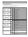
3. FAN PERFORMANCE AND CORRECTED AIR FLOW
(1) PEH-2.5EKHA2.TH
PEH-3EKHA2.TH
Corrected Air flow
Capacity
Input
Cooling
1.05
Correction factor
Fan Performance
Recommended range
Hi
150
0.95
0.9
17 20
1.2
100
50
0
15 17 20
25
30
Air flow (CMM)
Lo
Correction factor
External static pressure(Pa)
(1Pa = 0.1mmAq)
200
1.0
25
30
35
Heating
1.15
1.1
1.05
1.0
Air flow (CMM)
0.95
17 20
25
30
Air flow (CMM)
(2) PEH-4EKHSA2.TH
Corrected Airflow
Cooling
Fan Performance
Correction factor
1.05
Recommended range
Hi
150
1.0
0.95
0.9
20 23 25
30
35
40
Air flow (CMM)
100
Lo
1.15
0
Capacity
Input
Heating
1.1
50
20 23 25
30
35
Correction factor
External static pressure(Pa)
(1Pa = 0.1mmAq)
200
40
Air flow (CMM)
1.05
1.0
0.95
20 23 25
30
35
40
Air flow (CMM)
(3) PEH-5EKHSA2.TH
Corrected Air flow
Cooling
1.05
Correction factor
Fan Performance
Recommended range
Hi
150
1.0
0.95
0.9
28 30
100
1.15
50
0
25 28 30
35
35
40
45
50
Air flow (CMM)
Lo
40
Air flow (CMM)
45
50
Correction factor
External static pressure(Pa)
(1Pa = 0.1mmAq)
200
Capacity
Input
Heating
1.1
1.05
1.0
0.95
28 30
35
40
45
50
Air flow (CMM)
11
4. ELECTRICAL DATA
Indoor unit ········220V 50Hz 1phase
Outdoor unit ·····220V 50Hz 1phase / 380V 50Hz 3phase
Service Ref.
Indoor unit
Outdoor unit
Mode
PEH-2.5EKHA2.TH
PUH-2.5VKA2(.UK) PUH-3VKA2(.UK)
Heat
Capacity (W)
6,300
Total Input (kW)
2.76
Outdoor unit Indoor unit
Cool
Input (kW)
0.35
Current (A)
1.62
Starting current (A)
2.1
6,600
(8,400)
2.51
(4.31)
0.35
(2.15)
1.62
(9.80)
2.1
(10.3)
Input (kW)
2.41
Current (A)
Starting current (A)
PEH-3EKHA2.TH
Cool
Heat
2.1
8,100
(9,860)
3.27
(5.03)
0.35
(2.11)
1.62
(9.58)
2.1
(10.1)
2.16
3.13
11.18
10.02
52
52
PEH-4EKHSA2.TH PEH-5EKHSA2.TH
PUH-3YKA2(.UK) PUH-4YKSA3(2.UK) PUH-5YKSA3(2.UK)
Cool
Heat
2.1
8,100
(9,860)
3.27
(5.03)
0.35
(2.11)
1.62
(9.58)
2.1
(10.1)
2.92
3.13
14.67
13.69
54
54
7,500
3.48
0.35
1.62
Cool
Heat
2.4
10,200
(12,200)
3.56
(5.56)
0.40
(2.40)
1.86
(10.95)
2.4
(11.6)
2.92
3.17
5.23
4.88
34
34
7,500
3.48
0.35
1.62
Cool
Heat
3.0
12,800
(15,300)
4.65
(7.15)
0.52
(3.02)
2.47
(13.7)
3.0
(14.4)
3.16
4.19
4.13
5.29
5.28
7.32
7.21
37
37
49
49
9,500
3.57
0.40
1.86
12,200
4.71
0.52
2.47
Indoor unit ········230V 50Hz 1phase
Outdoor unit ·····230V 50Hz 1phase / 400V 50Hz 3phase
Service Ref.
Indoor unit
Outdoor unit
Mode
PEH-2.5EKHA2.TH
PUH-2.5VKA2(.UK) PUH-3VKA2(.UK)
Heat
Capacity (W)
6,350
Total Input (kW)
2.81
Outdoor unit Indoor unit
Cool
Input (kW)
0.37
Current (A)
1.64
Starting current (A)
2.2
6,650
(8,550)
2.57
(4.47)
0.37
(2.27)
1.64
(9.90)
2.2
(10.5)
Input (kW)
2.44
Current (A)
Starting current (A)
PEH-3EKHA2.TH
Cool
Heat
2.2
8,200
(10,130)
3.30
(5.23)
0.37
(2.30)
1.64
(9.90)
2.2
(10.6)
2.20
3.14
10.94
9.86
52
52
PEH-4EKHSA2.TH PEH-5EKHSA2.TH
PUH-3YKA2(.UK) PUH-4YKSA3(2.UK) PUH-5YKSA3(2.UK)
Cool
Heat
2.2
8,200
(10,130)
3.30
(5.23)
0.37
(2.30)
1.64
(9.90)
2.2
(10.6)
2.93
3.14
14.22
13.27
56
56
7,600
3.51
0.37
1.64
Cool
Heat
2.5
10,300
(12,500)
3.60
(5.80)
0.42
(2.62)
1.86
(11.43)
2.5
(12.1)
2.93
3.19
5.21
4.86
36
36
7,600
3.51
0.37
1.64
Cool
Heat
3.1
12,900
(15,600)
4.73
(7.43)
0.58
(3.28)
2.60
(14.30)
3.1
(14.8)
3.18
4.20
4.15
5.23
5.22
7.05
6.97
39
39
51
51
9,600
3.61
0.42
1.86
12,300
4.78
0.58
2.60
Indoor unit ········240V 50Hz 1phase
Outdoor unit ·····240V 50Hz 1phase / 415V 50Hz 3phase
Service Ref.
Indoor unit
Outdoor unit
Cool
Heat
Capacity (W)
6,400
Total Input (kW)
2.85
Input (kW)
0.39
Current (A)
1.66
Starting current (A)
2.3
6,700
(8,800)
2.62
(4.72)
0.39
(2.49)
1.66
(10.41)
2.3
(11.1)
Input (kW)
2.46
Current (A)
12
Starting current (A)
PEH-3EKHA2.TH
PUH-2.5VKA2(.UK) PUH-3VKA2(.UK)
Outdoor unit Indoor unit
Mode
PEH-2.5EKHA2.TH
Cool
Heat
2.3
8,300
(10,400)
3.33
(5.43)
0.39
(2.49)
1.66
(10.41)
2.3
(11.1)
2.23
3.15
10.68
9.78
52
52
PEH-4EKHSA2.TH PEH-5EKHSA2.TH
PUH-3YKA2(.UK) PUH-4YKSA3(2.UK) PUH-5YKSA3(2.UK)
Cool
Heat
2.3
8,300
(10,400)
3.33
(5.43)
0.39
(2.49)
1.66
(10.41)
2.3
(11.1)
2.94
3.15
13.82
12.89
58
58
7,700
3.54
0.39
1.66
Cool
Heat
2.6
10,400
(12,800)
3.63
(6.03)
0.44
(2.84)
1.87
(11.87)
2.6
(12.6)
2.94
3.20
5.16
4.81
37
37
7,700
3.54
0.39
1.66
Cool
Heat
3.2
13,000
(16,000)
4.81
(7.81)
0.65
(3.65)
2.76
(15.20)
3.2
(15.7)
3.19
4.21
4.16
5.24
5.22
6.89
6.81
40
40
53
53
9,700
3.64
0.44
1.87
12,400
4.86
0.65
2.76
5. STANDARD OPERATION DATA
PEH-2.5EKHA2.TH
Service Ref.
Total
Mode
Capacity
W
6,400
6,700
(8,800)
Input
kW
2.85
2.62
(4.72)
Electrical circuit
Volts
V
Amperes
A
Outdoor unit Service Ref.
Electrical circuit
10,400
13,000
3.33
(5.43)
3.54
3.33
(5.43)
3.54
3.63
(6.03)
3.64
4.81
(7.81)
4.86
1.50
1.50
1.50
1.50
240
240
240
240
1.66
(10.41)
1.66
1.66
(10.41)
1.66
PEH-4EKHSA2.TH PEH-5EKHSA2.TH
1.66
(10.41)
1.66
1.87
(11.87)
1.87
2.76
(15.20)
2.76
PUH-2.5VKA2(UK) PUH-3VKA2 (.UK) PUH-3YKA2 (.UK) PUH-4YKSA3 (2.UK) PUH-5YKSA3 (2.UK)
V
Amperes
Discharge
Pressure
Suction
Pressure
Discharge
Temperature
Condensing
Temperature
Suction
Temperature
Ref. pipe
length
8,300
PEH-3EKHA2.TH
Phase, Hz
Volts
8,300
7,700 (10,400) 7,700 (10,400) 9,700 (12,800) 12,400 (16,000)
PEH-2.5EKHA2.TH
Phase, Hz
Indoor side
PEH-4EKHSA2.TH PEH-5EKHSA2.TH
Cooling Heating Cooling Heating Cooling Heating Cooling Heating Cooling Heating
Indoor unit Service Ref.
Outdoor side
PEH-3EKHA2.TH
1.50
1.50
3.50
3.50
3.50
240
240
415
415
415
A
10.68
MPa·G 2.00
(Of/F·G) (20.4)
MPa·G 0.55
(Of/F·G) (5.6)
12.89
4.81
5.22
6.81
9.78
1.57
(16.0)
0.36
(3.7)
13.82
2.05
(20.9)
0.49
(5.0)
1.74
(17.8)
0.35
(3.6)
5.16
2.05
(20.9)
0.05
(5.1)
1.75
(17.9)
0.36
(3.7)
5.24
1.80
(18.4)
0.54
(5.5)
1.53
(15.6)
0.38
(3.9)
6.89
1.97
(20.1)
0.48
(4.9)
1.59
(16.2)
0.36
(3.7)
:
79.6
68.5
85.1
76.4
83.7
75.9
76.7
67.5
78.9
69.9
:
52.9
—
53.7
—
54.0
—
48.3
—
52.0
—
:
8.0
-1.9
6.2
-2.2
6.2
-2.1
7.1
-0.6
4.6
-1.4
m
5
5
5
5
5
5
5
5
5
5
D.B.:
27
20
27
20
27
20
27
20
27
20
W.B.:
19
15
19
15
19
15
19
15
19
15
D.B.:
17.3
33.0
16.0
36.9
16.0
36.9
14.6
37.2
14.6
37.1
D.B.:
35
7
35
7
35
7
35
7
35
7
W.B.:
24
6
24
6
24
6
24
6
24
6
SHF
0.79
—
0.78
—
0.78
—
0.80
—
0.74
—
BF
0.31
—
0.25
—
0.25
—
0.12
—
0.21
—
Intake
air temperature
Discharge air
temperature
Intake air
temperature
The unit of pressure has been changed to Mpa based on SI (International System of Units) in accordance with I.S.O.
(International Organization for Standardization).
Of/F
F•G)
The conversion factor is : 1(Mpa • G) =10.2 (O
13
5
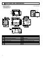
OUTLINES AND DIMENSIONS
Unit : mm (inch)
1. INDOOR UNITS
PEH-2.5EKHA2.TH
PEH-3EKHA2.TH
4 672(26 1/2)
600(24)
11
5
710(27 15/16)
(11 13/16)
300
1
3
900(36)
345(13 5/8)
2
155
155
59
(3 9/16)
15
22.5
145
562(22 1/8)
130
175
187
125
125
25
21
25
35
85
85
381(15)
730(28 3/4)
40
650(25 5/8)
300(11 13/16)
235(9 1/4)
25
10(3/8)
40
14
220
(8 11/16)
128
(5 1/16)
3.2
286
15
25
171
15
25.5
(2 3/4)
70
130
250
530(20 7/8)
20
690(27 3/16)
200(7 7/8)
457
508
200(7/8)
118
20
145
11
155
339(13 3/8)
15
40
9
10(3/8)
418(16 1/2)
20
(13/16)
24.5
90
70
8
50
44
(2 3/8)
75 60 265(10 1/2)
(3)
35
510(20 1/8)
92
7
105
(4 3/16)
20
(13/16)
6
100
(2 3/4)
530(7 7/8)
70
11
1
2
3
4
5
6
7
8
9
10
11
14
Refrigerant-pipe flared connection [9.52 (3/8)
Refrigerant-pipe flared connection [15.88 (5/8)
Electrical parts box
Drainage pan
Drainage pipe connection 1BSP (male)
Service panel (Indoor coil thermistor)
Room temperature thermistor
Heat insulator t10 (3/8)
Air intake duct flange
Air intake
Wiring entry (3-[22 (7/8) holes)
12
13
14
15
16
17
18
19
20
21
22
Suspension bolt holes (4-[12 (1/2))
14-[3 (1/8) holes
For air outlet duct connection (12-[3 (1/8) holes)
Air outlet
Mounting plate
Air outlet duct flange
Heat insulator t10 (3/8)
Service space (opening) in the ceiling
Service panel (Room temperature thermistor)
Service panel (booster heater)
Mounting plate (option)
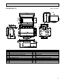
Unit : mm (inch)
PEH-4EKHSA2.TH
600(24)
(11 13/16)
300
4 942(37 1 16)
980(38 9 16)
11
1
3
35
118
175
200(7 7/8)
187
250
200(7 7/8)
4✕65(=260)
286
65
27.5 3✕65(=195) 27.5
381(15)
1000(3 15 16)
920(36 1 4)
500(19 11 16)
40
Refrigerant-pipe flared connection [9.52 (3/8)
Refrigerant-pipe flared connection [19.05 (3/4)
Electrical parts box
Drainage pan
Drainage pipe connection 1BSP (male)
Service panel (Indoor coil thermistor)
Room temperature thermistor
Heat insulator t10 (3/8)
Air intake duct flange
Air intake
Wiring entry (3-[22 (7/8) holes)
12
13
14
15
16
17
18
19
20
21
22
210(8 1 4)
10(3/8)
14
250(9 13 16)
98
(3 7/8)
3.2
40
21
22.5
7✕65(=455)
35
15
65 65 65 65 65 65 65
15
22.5
8
171
(2 3/4)
70
130
530(20-7/8)
20
960(37 13 16)
65
11
(3 9/16)
90
15
15
20
10(3/8)
39.5
63
55
457
25.5
508
418(16 1/2)
339(13 3/8)
20(13/16)
65 65 65 65 65 65 65 65 65 65 65 40
9
44
11✕65(=715)
70 40
(9 5/8)
245
562(22 1/8)
795(31 5 16)
42.5
(3 3/8) (2 3/4)
85 70
92
7
90
130
6
(3 9/16)
20
(13/16)
345(13 5/8)
2
(2 3/4)
530(7 7/8)
70
900(36)
5
100
1
2
3
4
5
6
7
8
9
10
11
Suspension bolt holes (4-[12 (1/2))
34-[3 (1/8) holes
For air outlet duct connection (24-[3 (1/8) holes)
Air outlet
Mounting plate
Air outlet duct flange
Heat insulator t10 (3/8)
Service space (opening) in the ceiling
Service panel (Room temperature thermistor)
Service panel (booster heater)
Mounting plate (option)
15
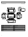
Unit : mm (inch)
PEH-5EKHSA2.TH
600(24)
(11 13/16)
300
1180(46 7 16)
4 1142(44 15 16)
11
11
1
(2 3/4)
530(7 7/8)
70
900(36)
20
11
4✕65(=260)
118
187
27.5
35
110(4 5 16)
1200(47 1 4)
1120(44 1 8)
900(35 7 16)
21
65
27.5
27.5 3✕65(=195) 27.5
381(15)
40
14
250(9 13/16)
98
(3 7/8)
3.2
40
13✕65(=855)
15
65 65 65 65 65 65 65 65 65 65 65 65 65
286
(2 3/4)
70
8
171
15
25.5
130
1160(45 11 16)
65
562(22 1/8)
20
10(3/8)
339(13 3/8)
39.5 39.5
40
15
65 65 65 65 65 65 65 65 65 65 65 65 65 65
15
40
418(16 1/2)
20(13/16)
(3 9/16)
90
70
63
55
457
44
35
42.5
14✕65(=910)
9
508
995(39 3 16)
130
(9 5/8)
245
200(7 7/8) 200(7/8)
530(20 7/8)
(3 3/8) (2 3/4)
85 70
175
7
250
6
(3 9 16) 90
20
(13/16)
345(13 5/8)
2
3
92
5
100
1
2
3
4
5
6
7
8
9
10
11
16
Refrigerant-pipe flared connection [9.52 (3/8)
Refrigerant-pipe flared connection [19.05 (3/4)
Electrical parts box
Drainage pan
Drainage pipe connection 1BSP (male)
Service panel (Indoor coil thermistor)
Room temperature thermistor
Heat insulator t10 (3/8)
Air intake duct flange
Air intake
Wiring entry (3-[22 (7/8) holes)
12
13
14
15
16
17
18
19
20
21
22
Suspension bolt holes (4-[12 (1/2)
40-[3 (1/8) holes
For air outlet duct connection (36-[3 (1/8) holes)
Air outlet
Mounting plate
Air outlet duct flange
Heat insulator t10 (3/8)
Service space (opening) in the ceiling
Service panel (Room temperature thermistor)
Service panel (booster heater)
Mounting plate (option)
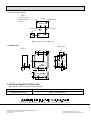
Unit : mm (inch)
2. REMOTE CONTROLLER
FILTER
CHECK MODE
TEST RUN
TEST RUN
120
FILTER
CHECK MODE
050
18
130
83.5
Rear side wiring arrangement opening.
46
CAUTION
SW18
SW17
17
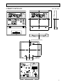
6
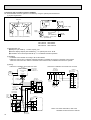
WIRING DIAGRAM
PEH-2.5/3/4/5EKH(S)A2.TH
SYMBOL
C
CN1<R.B>
CN2<R.B>
CN2L<I.B>
CN51<I.B>
F<I.B>
FS
H
I.B
LCD
MF
R.B
SW1<I.B>
SW2<I.B>
SW3<I.B>
SW5<I.B>
SW6<I.B>
NAME
FAN MOTOR CAPACITOR
PROGRAM TIMER CONNECTOR
REMOTE SWITCH CONNECTOR
LOSSNAY CONNECTOR
CENTRALLY CONTROL CONNECTOR
FUSE 16.3A 250V
THERMAL FUSE
ELECTRIC HEATER
INDOOR CONTROLLER BOARD
LIQUID CRYSTAL DISPLAY
INDOOR FAN MOTOR
REMOTE CONTROLLER BOARD
MODE SELECTOR
ADDRESS SELECTOR
EMERGENCY OPERATION SWITCH
MODEL SELECTOR
MODEL SELECTOR
REMOTE CONTROLLER
NAME
ADDRESS SELECTOR
FUNCTION SELECTOR
TRANSFORMER
POWER SUPPLY TERMINAL BLOCK
INDOOR/OUTDOOR CONNECTING WIRE
TERMINAL BLOCK
REMOTE CONTROLLER TRANSMISSION
LINE TERMINAL BLOCK
ROOM TEMPERATURE THERMISTOR
(0:/15kΩ. 25 :/5.4kΩ)
INDOOR COIL THERMISTOR
(0:/15kΩ. 25 :/5.4kΩ)
FAN MOTOR AUXILIARY RELAY
FAN MOTOR AUXILIARY RELAY
FAN MOTOR AUXILIARY RELAY
VARISTOR
ELECTRIC HEATER CONTACTOR
SYMBOL
SW17<R.B>
SW18<R.B>
T
TB2
TB4
TB5.6
RT1
RT2
X4<I.B>
X5<I.B>
X6<I.B>
ZNR<I.B>
88H
NAME
OVER HEAT PREVENTION THERMAL
SWITCH
SYMBOL
26H
RT1
INDOOR UNIT
RT2
R.B
DRAIN CN50
X6 X5 X4
X6
TB4
TB2
BLU
T
R
C
6
88H
YLW
6 5 4 3 2 1
6 5
MF
RED
26H
BLU
RED
GRN/YLW
3
88H
5
RED
BLU
FS
H
1
2
240
230
220
YELLOW
ORANGE
RED
2. Since the outdoor side electric wiring may change be sure to check the outdoor unit electric wiring
for servicing.
3. Indoor and outdoor connecting wires are made with polarities,make wiring matching terminal numbers (1 and 2).
:Connector,
:PC board
4. Symbols used in wiring diagram above are. /:Terminal block.
insertion tab.
5. Emergency operation
If a trouble occurs with either the remote controller or the indoor microcomputer and no other truble
exists. emergency operation for cooling or heating can be performed by changing the setting of dip
switch (SW3<I.B>) on the indoor controller board.
(emergency dry operation is not possible.)
[Check items]
(1)Make sure that no other trouble exists with the outdoor unit .Trouble with the outdoor unit prevents emergency operation. (If any trouble exists with the outdoor unit error code “P8”will be displayed on the remote
controller and the trouble position will be shown on the outdoor controller board LED. See electric wiring
diagram of the outdoor unit for details.)
(2)Make sure that there is no trouble with the indoor fan.
Emergency operation will be a continuous run with the power ON/OFF (ON/OFF with the remote controller
is not possible).
[Emergency operation procedure]
(1) Set the dip switch (SW3<I.B>) on the indoor controller board to 1•2•3 on and 4 off for cooling, and
2•3•4 on and 1 off for heating.
(2) Turn on the outdoor unit side circuit breaker.
(3) During emergrncy operation indoor fan runs at High speed.
(4) Thermostat will not function. Cold air blows out for defrosting during heating thus do not operate defrosting for a long time.
(5) Emergency cooling should be limited to 10 hours maximum(the indoor unit heat exchanger may freeze).
18
S
YLW
YLW
M2 M1 M0
RED
M3
1. Since the indoor transformer (T) is connected with 240V power, if 220, 230V power is used.
Change the wiring connection showing fig : W1.
when power supply is fig :W1
230V
220V
CN51
CN20 CN21 CENTRALLY
INTAKE PIPE
CONTROL
HEATER
CN24
ZNR
2 1
F
TRANS
ORN
YLW
X4
2 1
ORN
RED
BLK
BLU
BRN
WHT
BRN
X5
2 1
WHT
BLU
TRANS
CN4T
4 3 2 1
YLW
BLU
1
N
OFF
ON
TO
REMOCON
REMOCON POWER OUTDOOR
CN22
CN40
CN30
4 3 2 1
3 2 1
3
TO OUTDOOR UNIT
CONNECTING WIRES 2
DC 12V(polar)
1
AC220~240V
50Hz
5 4 3 2 1
56 4321 432 1 4 3 2 1 1 0 9 8 7 6 5 4 3 2 1 4 3 2 1
2
L
SW3
CN2L
LOSSNAY
TB5
POWER SUPPLY
~ (1 PHASE)
SW1
WHT
CN2
3 2 1
SW5 SW6
14.5VAC RED
RED
BRN
BRN
10.8VAC
OFF
ON
SW2
YLW
ORN
RED
CN1
5 4 3 2 1
SW17
87654321
TB6
BRN
ORN
YLW
OFF
ON
4321
I.B
BO2
TRANSMISSION WIRES DC12V
AO1
SW18
7
REFRIGERANT SYSTEM DIAGRAM
Unit : mm
PEH-2.5EKHA2.TH/PUH-2.5 VKA2(.UK)
PEH-3EKHA2.TH/PUH-3 VKA2(.UK)
PUH-3 YKA2(.UK)
Refrigerant flow in cooling
Refrigerant flow in heating
R.V.coil
Heating:ON
Cooling:OFF
High pressure
control switch
Oil separator
Refrigerant pipe
(option)
15.88mm( 5/8¨)
(With heat insulator)
Indoor unit
Flexible tube
Indoor
heat
exchanger
4-way valve
Service
port
Outdoor unit
Outdoor heat exchanger
Ball Valve
Strainer
Thermistor
RT
Service
port
Flared
connection
Strainer
Bypass valve
Accumulator
Thermistor
TH2
Capillary
tube
Restrictor
valve
Restrictor
valve
Compressor
Distributor
with strainer
Refrigerant pipe
(option)
9.52 mm( 3/8¨)
(With heat insulator)
Capillary
tube
PEH-2.5 (O.D. 3.2✕ I.D. 1.8 -R430)
PEH-3 (O.D. 4.2✕ I.D. 2.0 -R400)
Ball Valve
(with service port)
Strainer
PUH-2.5
(O.D. 4.0✕ I.D.2.4 -R1550)
PUH-3
(O.D. 4.0✕ I.D.2.4 -R1070)
PEH-4EKHSA2.TH/PUH-4YKSA3(2.UK)
High pressure
control switch
Oil separator
Refrigerant pipe
(option)
19.05mm( 3/4¨)
(With heat insulator)
Indoor unit
Flexible tube
Indoor
heat
exchanger
4-way valve
Service
port
Outdoor unit
Outdoor heat exchanger
Ball Valve
Strainer
Thermistor
RT
Restrictor
valve
Service
port
Strainer
Flared
connection
Bypass valve
Capillary
tube
Accumulator
Thermistor
TH2
Restrictor
valve
Compressor
Flexible tube
Distributor
with strainer
Capillary
tube
PEH-4 (O.D. 4.0✕ I.D. 2.4 -R550)
Refrigerant pipe
(option)
9.52 mm( 3/8¨)
(With heat insulator)
Ball Valve
(with service port)
Strainer
PUH-4
(O.D. 3.2✕ I.D. 2.0
-R820)✕ 2pcs
PEH-5EKHSA2.TH/PUH-5YKSA3(2.UK)
High pressure
control switch
Oil separator
Refrigerant pipe
(option)
19.05mm( 3/4¨)
(With heat insulator)
Indoor unit
Flexible tube
Indoor
heat
exchanger
4-way valve
Service
port
Outdoor unit
Outdoor heat exchanger
Ball Valve
Strainer
Thermistor
RT
Restrictor
valve
Service
port
(check)
Strainer
Flared
connection
Bypass valve
Capillary
tube
Accumulator
Thermistor
TH2
Restrictor
valve
Distributor
with strainer
Capillary
tube
PEH-5 (O.D. 4.0✕ I.D. 3.0 -R330)
Capillary tube
Compressor
Flexible tube
Refrigerant pipe
(option)
9.52 mm( 3/8¨)
(With heat insulator)
Ball Valve
(with service port)
THERMAL
SWITCH
Strainer
PUH-5
(O.D. 4.0✕ I.D. 2.4
-R840)✕ 2pcs
19
8
OPERATION FLOW-CHART
MAIN OPERATION
START
NO
Power circuit
breaker
1
YES
YES
Check SW
ON twice
NO
Operation SW
ON
w1
YES
NO
“OFF” timer
YES
NO
NO
Set time
complete
“ON” timer
YES
YES
Set time
complete
NO
YES
w2
NO
Trouble
NO
Remote controller
operation display
YES
STOP
Trouble STOP
Operating mode YES
(COOL)
PROTECTION DEVICE
SELF HOLD RELEASE
PROTECTION DEVICE
SELF HOLD
NO
Remote controller
indicator lamp OFF
w3
Remote controller
trouble display
NO
w4
Auxiliary heater OFF
w6
Operating mode YES
w7
(FAN)
FAN
operation
NO
Auto COOL/HEAT
operation
Outdoor side
Compressor OFF
w5
Fan STOP
Four-way valve OFF
w1 In addition, the centralized control and remote control can be operated.
w2 The modes which indicate the sources of trouble are listed below.
● EO-Signal transmitting/receiving error
● P1-Room temperature thermistor malfunction
● P2-Indoor coil thermistor malfanction
● P4-Drain sensor malfunction
● P5-Drain overflow
● P6-Coil frost/overheat protection
● P7-System error
● P8-Outdoor unit trouble
w3 The CHECK swich will show if an error has occurred in the past.
w4 Fan runs on low speed for 1 minute in order to remove overheat air.
w5 The 3-minute (6 minutes … heating mode) time-delay functions after compressor stops.
w6 FAN or AUTO mode is selected by the indoor dipswitch setting.
w7 In FAN mode, fan speed depend 3 on the remote controller setting. (Compressor is OFF.)
20
DRY operation
Operating mode YES
(HEAT)
HEAT operation
NO
Indoor side
Fan STOP
COOL operation
Operating mode YES
(DRY)
COOLING OPERATION
COOL operation
Four-way valve/OFF
w9
NO
Compressor
thermostat
ON
YES
NO
Allowance
cancel
NO
YES
3-minute
time delay
YES
6-minute
time delay
NO
NO
6 minute
time delay
NO
NO
3-minute
compressor
operation
w10
YES
Aliowance
period
Allowance set
Coil frost protection
YES
YES
Coil frost
prevention
NO
w11
NO
Cooling area
YES
NO
10-minute
compressor
operation
NO
YES
YES
Allowance cancel
FAN speed
LOW
YES
Coil frost
protection
NO
NO
NO
Indoor coil
temperature is
10°C or higher
16-minute
compressor
operation
YES
YES
Indoor pipe
YES
temperature is
1°C or lower
NO
Coil frost
prevention
Compressor ON
1 min.continue
FAN speed YES
LOW 5 min.
elapse
NO
Outdoor unit
trouble
3-minute
time delay
Coil frost
prevention release
Compressor OFF
1
w8 When operating TEST RUN, the thermostat will be continuously ON.
w9 After 3 minute compressor operation, if the indoor coil thermistor reads -15: or below for 3 minutes, the compressor will
stop for 6 minutes.
w10Cooling area : Indoor coil temperature is more than 5 degrees above the room temperature.
Heating area : Indoor coil temperature is more than 5 degrees below the room temperature.
FAN area : Indoor coil temperature is within 5 degrees either way of the room temperature.
21
DRY OPERATION
DRY
operation
Four-way valve / OFF
YES
Room tempereature is
18°C or lower
w12
NO
NO
During
compressor ON
YES
3-minute
compressor
operation
NO
NO
YES
NO
w11
Compressor &
thermostat ON
YES
Compressor &
thermostat
ON
NO
Compressor ON
time completes
10-minute
compressor
OFF
w13
10-minute compressor
OFF timer start
Compressor ON
time set
Compressor OFF
Compressor ON
w14
w14
Fan speed LOW
1
w13
w14
22
NO
YES
YES
w11
w12
w11
NO
YES
Fan STOP
YES
3-minute
time delay
Refer to page 26~27.
When room temperature is 18: or below, the compressor cannot operate.
When room temperature rises over 18:, the compressor starts after a 3-minute time delay.
Compressor ON time is decided by room temperature. Refer to page 26~27.
In dry operation, compressor ON makes the fan speed LOW and compressor OFF stops the fan.
It is not possible to set the fan speed with the remote controller
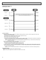
HEATING OPERATION
w11
Heat operation
Heating area
YES
NO
Defrpsting
Defrost release
NO
Defrost
30 min. elapse
YES
2
YES
Outdoor unit trouble
NO
Four-way valve ON
1
YES
Hor adjust
in process
NO
YES
Compressor
ON
NO
w9
YES
Compressor
thermostat ON
3 min.restart
prevention
YES Indoor piping
35°C or higher
10-minute
compressor
operation
YES
NO
Allowance cancel
YES
Allowance cancel
YES 6 min. restart
prevention
2
NO Indoor piping
-15°C or lower
Indoor piping YES
55°C or lower
w11
NO
NO Auxiliary heater
ON
Compressor ON
FAN SPEED
Very low airflow
w11
Airflow area YES
20 min.elaspe
Overheat remote
START
NO
w11
Compressor OFF
FAN SPEED
setting nitch
Hot adjust
release
YES
Outdoor unit
trouble
Airflow area
Heating area
YES
Auxiliary heater
ON
FAN SPEED NO
Low 2 min.
elapse
YES
Auxiliary heater
OFF
NO w10
YES
NO Auxiliary heater
thermostat ON
YES
NO Indoor piping
60°C or higher
FAN STOP
FAN SPEED
very low
FAN SPEED
Low
NO
YES
Heating
area
NO
Hot adjust start
YES
Outdoor unit
trouble
NO
HOT adjust NO
6 min. elapse
FAN setting notch
NO
Airflow area
Cooling area
NO
Indoor unit
70°C or higher
YES
YES
Defrost operation
START
Allowance
period
Four-way valve
OFF
YES
Overload protect
NO
6-minute restart
prevention
Allowance set
1
Compressor OFF
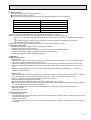
AUTOMATIC COOLING/HEATING OPERATION
Auto COOL/HEAT
operation
w16
NO
1
Initial mode
w17
YES
NO
T1 >
= T0
YES
COOL mode
COOL mode
HEAT mode
NO
YES
NO
NO
T1 < (T0 - 3)
YES
After 15min.
T1<(T0-2)
YES
YES
After 15min.
T1>(T0 + 2)
YES
NO
NO
COOL operation
T1>(T0 + 2)
HEAT operation
1
HEAT operation
Cool mode
set
1
w15 ( i ) Until Low airflow is set while in hot adjustment
( ii )While defrosting (FAN STOP)
(iii)When thermostat is OFF
In the case of( i ), (ii) and (iii) above, airflow is horizontal regardless the VANE setting.
w16 When AUTO operation is started, COOL or HEAT mode is selected automatically.
w17 T1 : Room temperature.
To : Set temperature
23
9
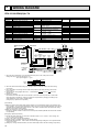
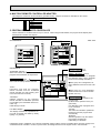
MICROPROCESSOR CONTROL
1.OUTLINE OF MICROPROCESSOR CONTROL
INPUT to remote controller
● OFF-ON switching.
● COOL/DRY-AUTO-HEAT selector switching.
● Thermostat setting.
● TIMER mode selector-switching and Timer
setting.
● HIGH-LOW fan speed switching.
● TEST RUN switching.
● CHECK mode switching.
(Self diagnostic trouble shooting)
Remote controller board
● Processes and transmits
orders.orders.
OUTPUT to remore controller
Remote controller
● LCD indicator
FILTER
CHECK MODE
TEST RUN
Indoor
unit
12VDC
Non-polar, two-wire cable
maximum length 500 meters
INPUT from indoor unit
● Room temperature thermistor (RT1)
● Indoor coil thermistor (RT2)
● Drain sensor
OUTPUT to indoor unit
Signal
Indoor controller board
● Receives orders from remote controller and
temperature data from indoor unit.
● Processes orders and data.
● Controls indoor and outdoor operation.
● Self diagnostic function.
w System control operation.
w Emergency operation.
w Set by dipswitch on indoor controller board.
● Transmits the power to remote controller.
Independent Control of
Outdoor Unit
● Compressor protection
device working
● Defrosting
START-STOP
● Fan speed control.
● Crankcase heater control
ON-OFF.
● Self diagnostic function
24
Polar three-wire cable
Outdoor unit
12VDC
● Autovane’s angle setting.
● Booster heater ON-OFF Control.
● Drain pump : ON-OFF.
● Emergency stop.
1
2
3
OUTPUT to outdoor unit
1 2 3
● Compressor and
outdoor fan : ONOFF
● Operation mode
change :COOLHEAT.
2. INDOOR UNIT CONTROL
2-1COOL operation
<How to operate>
1 Press POWER ON/OFF button.
2 Press the
button to display “
FILTER
”
3 Press the
TEMP button to set the desired temperature.
NOTE: Set temperature changes 1°C when the
or
button is pressed one time.
Cooling 19 to 30°C
CHECK MODE
TEST RUN
<COOL operation time chart>
Operation starts by
POWER button
ON.
Room temperature
becomes equal to
set temperature.
Room temperature
rises above set
temperature.
Operation stops by
POWER button
OFF.
ON
Thermostat
OFF
ON
Indoor fan
LOW or HIGH
LOW or HIGH
OFF
ON
Booster heater
OFF
ON
Compressor
OFF
OFF
Minimum 3 minutes w1
w1 Even if the room temperature rise above the set temperature during this period, the compressor will not start until this period has ended.
(1) Compressor control
1 3-minute time delay
To prevent overload, the compressor will not start within 3 minutes after stop.
2 The compressor runs when room temperature is higher than set temperature.
The compressor stops when room temperature is equal to or lower than the set temperature.
3 The compressor stops in check mode or during protective functions.
4 Coil frost prevention
To prevent indoor coil frost, the compressor will stop when the indoor coil thermistor (RT2) reads 1: or below after the
compressor has been continuously operated for at least 16 minutes or more. When the indoor coil temperature rises to
10°C or above, the compressor will start after a 3-minute time delay.
NOTE : By turning OFF the dipswitch SW1-5 on indoor controller board, the start temperature of coil frost prevention
changes from 1: to -3:.
5 Coil frost pretection
When indoor coil temperature becomes -15: or below,coil frost protection will proceed as follows.
<Start condition>
After the compressor has been continuously operated for 3 minutes or more,and the indoor coil temperature has been 15: or below for 3 minutes,the coil frost protection will start.
<Coil frost protection>
Compressor stops for 6 minutes,and then restarts.
If the start condition is satisfied again during the first 10 minutes of compressor operation,both the indoor and outdoor units
stop,displaying a check code of “P8”on the remote controller.
<Termination conditions>
Coil frost protection is released when the start condition is not satisfied again during the allowance,or when the COOL
mode stops or changes to another mode.
(2) Indoor fan control
Indoor fan speed LOW/HIGH depends on the remote controller setting.
However,if an outdoor unit abnormality is detected,the indoor fan speed will be LOW, regardless of the remote controller
setting.
25
2-2 DRY operation
<How to operate>
1 Press POWER ON/OFF button.
2 Press the
button to display “
FILTER
3 Press the
CHECK MODE
TEST RUN
”
TEMP button to set the desired temperature.
NOTE: The set temperature changes 1°C when the
button is pressed one time.
Dry 19 to 30°C
<DRY operation time chart>
Operation starts by
POWER button
ON.
Room temperature
becomes equal to
set temperature.
Room temperature
rises above set
temperature.
Operation stops by
POWER button
OFF.
ON
Thermostat
OFF
LOW speed
Low speed
ON
Indoor fan
OFF
ON
Booster heater OFF
ON
Compressor
OFF
OFF
Minimum 3 minutes w1
w1 Even if the room temperature rises above the set temperature during this period, the compressor will not start until this period has ended.
(1) Compressor control
13-minute time delay
To prevent overload, the compressor will not start within 3 minutes after stop.
2The compressor runs when the room temperature is higher than the set temperature.
The compressor stops when the room temperature is equal to or lower than the set temperature.
3The compressor stops in check mode or during protective functions.
26
or
4The compressor will not start when the room temperature is below 18°C.
The compressor starts intermittent operation when the power is turned ON with room temperature above 18°C. The compressor ON/OFF time depends on the thermostat ON/OFF and the following room temperatures.After 3-minute compressor operation,
● If the room temperature thermistor reads above 28°C with thermostat ON, the compressor will operate for 6 more minutes and then stop for 3 minutes.
● If the room temperature thermistor reads 26°C~28°C with thermostat ON, the compressor will operate for 4 more minutes and then stop for 3 minutes.
● If the room themperature thermistor reads 24°C~26°C with thermostat ON, the compressor will operate for 2 more
minutes and then stop for 3 minutes.
● If the room temperature thermistor reads below 24°C with thermostat ON, the compressor will stop for 3 minutes.
● If the thermostat is OFF regardless of room temperature, the compressor will stop for 10 minutes.
5Coil frost protection
Coil frost protection in DRY operation is the same as in COOL operation.
6Coil frost prevention
Coil frost prevention does not operate in DRY operation.
(2) Indoor fan control
The indoor fan runs on LOW speed during compressor operation. The fan speed can not be changed with the remote controller. Also, the indoor fan does not run during compressor OFF.
(3) Detecting abnormalities in the outdoor unit
An abnormality in the outdoor unit can not be detected in DRY operation.
27
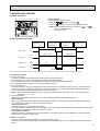
2-3 HEAT operation
<How to operate>
1 Press POWER ON/OFF button.
2 Press the
button to display “
”
FILTER
3 Press the
CHECK MODE
TEST RUN
TEMP button to set the desired temperature.
NOTE: The set temperature changes 1°C when the
button is pressed one time.
Heating 17°C to 28°C
<Display in HEAT operation>
or
[DEFROST]
The [DEFROST] symbol is only displayed during the defrost operation.
[STANDBY]
The [STANDBY] symbol is only displayed from the time the heating
operation starts until the heated air begins to blow.
<HEAT operation time chart>
Operation starts by
POWER button
ON.
Room temperature
becomes equal to
set temperature.
Room temperature
falls below set temperature.
Operation stops by
POWER button
OFF.
ON
Thermostat
OFF
Extra LOW w1
ON
Indoor fan
LOW
LOW or HIGH
Extra LOW w1
LOW or HIGH
OFF
ON
Booster heater
OFF
Hot adjustment
Hot adjustment
w1 Changeable by indoor
dipswitch SW1- 7
and SW1- 8.
OFF during thermostat OFF
hot adjustment
defrosting
ON
Compressor
OFF
Minimum 3 minutes w2
w2 Even if the room temperature falls below the set temperature during this period, the compressor will not start until this period has ended.
28
(1) Compressor control
13-minute time delay
To prevent overload, the compressor will not start within 3, minutes after stop.
2The compressor runs when the room temperature is lower than the set temperature.
The compressor stops when the room temperature is equal to or higher than the set temperature.
3The compressor stops in check mode or during protective functions.
4Overheat protection
<Start condition>
When the indoor coil thermistor reads 70°C or above, the overheat protection will start.
<Overheat protection>
The compressor stops for 6 minutes, and then restarts.
If the start condition is satisfied again within 10 minutes of compressor operation, both the indoor and outdoor units stop,
displaying a check code of “P6” on the remote controller.
<Termination conditions>
Overheat protection is terminated when the start condition is not satisfied again during the allowance (10-minute compressor operation), when operation mode changes to other mode, or when thermostat turns OFF.
(2) Indoor fan control
(a) Normal control
( i )The indoor fan runs on EXTRA-LOW speed during the thermostat OFF.
EXTRA-LOW speed can be changed to LOW or HIGH speed by setting the dipswitch SW1-7 and SW1-8.
If the indoor coil temperature becomes more than 5 degrees below the room temperature during the thermostat
OFF, the indoor fan will stop. After, when the indoor coil temperature becomes within 5 degrees of room temperature, the indoor fan will run on EXTRA-LOW speed.
( ii )Hot adjustment
Hot adjustment is a warm-up for HEAT operation
<Start conditions>
The hot adjustment works under any of the follwing conditions.
● HEAT operation starts.
● Defrosting ends.
● Thermostat turns ON.
[Hot adjustment]
Initially, the indoor fan runs on EXTRA-LOW speed. When 5 minutes have passed or the indoor coil temperature
exceeds 35°C, the fan speed changes to LOW. Two minutes later, the hot adjustment ends. Then, the fan speed
depends on the remote controller setting.
(iii)The indoor fan stops when the indoor coil temperature is within 5 degrees either way of room temperature.
(iv)To eliminate the remaining heat, the indoor fan runs for the first 1 minute after the booster heater is turned OFF.
(3) Booster heater control
When the room temperature is 3 degrees below the set temperature, the booster heater will turn ON.
When the room temperature is equal to the set temperature, booster heater will turn OFF.
During the hot adjustment, the booster heater will not work.
<Overheat prevention>
When the indoor coil thermistor rises to 60°C or above, the booster heater cannot work.
When the indoor coil thermistor falls to 55°C or below, the booster heater can work.
(4) Detecting abnormalities in the outdoor unit
When the outdoor unit is determined to be abnormal by the following causes, the compressor will stop and the check code
“ P8 ” will appear on the remote controller display.
1 During compressor ON after hot adjustment
1 If the difference between the indoor coil temperature and room temperature is in the RANGE B, the indoor fan will stop.
2 Within 20 minutes after entering RANGE B (except for the first 10 seconds),
w1(See the next page.)
a) If the temperature difference enters RANGE A, the hot adjustment stasrts,
b) If the temperature difference is still in RANGE B, the outdoor unit is deemed abnormal.
c) If the temperature difference enters RANGE C, defrosting starts.
Within 20 minutes after entering RANGE C,
●If the temperature difference does not return to RANGE B,the outdoor unit is deemed abnormal.
●If the temperature difference returns to RANGE B, the next 20 minutes is an allowance period. If the difference enter
RANGE A during the allowance, defrosting ends and the hot adjustment starts. If the difference does not enter
RANGE A during the allowance, the outdoor unit is deemed abnormal.
2 During compressor ON in hot adjustment
After 20 minutes of defrosting in hot adjustment, if the temperature difference is still in RANGE C, the outdoor unit is
determined to be abnormal.
3 During compressor OFF
After 20 minutes of thermostat OFF, if the indoor coil thermistor reads -25°C or below, the outdoor unit is determined to
be abnormal.
29
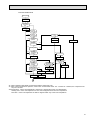
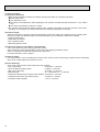
(5) Indoor coil thermistor abnormality detection
An abnormality can be detected during compressor ON, except for the following.
●For the first 20 minutes after the temperature difference between the indoor coil temperature and room temperature
enters the RANGE C.
●When the temperature difference enters the RANGE C until it moves to the RANGE B.
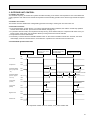
(6) Defrosting operation
After the outdoor unit starts the defrosting operation, when the temperature difference beetween the indoor coil temperature and room temperature gets out of RANGE A and into RANGE B, the indoor unit starts the defrosting mode. After the
outdoor unit stops the defrosting operation, when the temperature difference returns to the RANGE A, the indoor unit stops
the defrosting mode. While the indoor unit is in the defrosting mode, the indoor fan and the booster heater stop.
w1 RANGE A : Indoor coil temperature is more than 5 degrees above room temperataure.
RANGE B : Indoor coil temperature is within 5 degrees either way of room temperature.
RANGE C : Indoor coil temperature is more than 5 degrees below room temperature
Indoor coil temperature
minus room temperature
(degree)
+5
RANGE A
0
RANGE B
-5
30
RANGE C
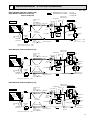
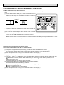
2-4 AUTO operation (Automatic COOL/HEAT change over operation)
<How to operate>
1 Press POWER ON/OFF button.
2 Press the
button to display “
FILTER
3 Press the
CHECK MODE
TEST RUN
”
TEMP button to set the desired temperature.
NOTE: The set temperature changes 1°C when the
or
button is pressed one time.
Automatic 19 to 28°C
●“AUTOMATIC” works to change by itself the operation
mode either to cooling or heating according to the room
temperature.
(1) Initial mode
1 When AUTO operation starts after unit OFF.
● If the room temperature is higher than the set temperature, operation starts in COOL mode.
● If the room temperature is equal to or lower than the set temperature, operation starts HEAT mode.
2 When AUTO operation starts after COOL or HEAT operation, the previous mode continues.
(2) Mode change
1 HEAT mode changes to cool mode when 15 minutes have passed since the room temperature became 2 degrees
above the set temperature.
2 COOL mode changes to HEAT mode when 15 minutes have passed since the room temperature became 2 degrees
below the set temperature.
To:Set temperature (19
(degree)
28
When room temperature becomes2degrees above the set temperature,the operation mode can not be changed
for 15 minutes.
)
1Mode change (HEAT
COOL)
To + 2
To + 1
To
To - 1
To - 2
15 minutes
Start
15 minutes
Minimum 3 minutes
COOL mode
HEAT mode
Compressor
2Mode change
(COOL HEAT)
HEAT mode
ON
OFF
Minimum 3 minutes
(3) Temperature range
AUTO operation is available under the outside air temperatures as follows.
-9
0
10
20
30
40
46
(Outside air temperature)
-5
-8.5
Cooling range
Heating range
31
2-6 TIMER operation
<Timer function>
AUTO STOP ·········The air conditioner stops after the set time lapses.
AUTO START ········The air conditioner starts after the set time lapses.
AUTO OFF ············Timer is not active.
<How to operate>
1. Press POWER ON/OFF button.
FILTER
CHECK MODE
TEST RUN
2. Press “ ” button to select AUTO STOP or AUTO START.
3. Press “
” button to set desired time.
Time setting is in 1 hour units for up to 24 hours.
Each time HOURS button is pressed, set time increases by 1 hour.
When HOURS button is pressed and held, the set time increases
by 1 hour every 0.5 seconds.
4. To cancel the timer operation, press POWER ON/OFF button.
<Timer setting example>
OFF
This setting will stop the air conditioner in 8 hours.
With the lapse of time, time display changes in 1 hour units, showing remaining time.
2-7 Test run
<Before test run>
● After installing, wiring, and piping the indoor and outdoor units, check for refrigerant leakage, looseness in power supply or
contorol wiring, and mistaken polarity.
● Use a 500-volt megger to check the resistance between the power supply terminal block and ground to make sure that it is
at least 1.0MΩ.
Attention:
Do not use the air conditioner if resistance is less than 1.0MΩ.
Remote controller
FILTER
1
Turn on main switch.12 hours before proceeding to step 2 to allow
for crankcase heater operation.
2
Push the TEST RUN button twice and indication of TEST RUN will
be shown on the liquid crystal display.
3
Press the
button to display
, COOL/DRY(or HEAT)to
confirm that cool (or warm) air is blown out.
(At heating operation, there may be a short delay before warm air
begins to blow out.)
4
Push
properly.
5
Check the operation of outdoor unit fans.This unit controls the rotation speed and performance capacity of fans.ln some cases,it may
rotate at low speed as the condition of outside air requires and the
speed will be kept unless the performance has become deficient.
Therefore,when the condition of outside air demands,there may be
such cases as the fan stops or rotates reversely.
Please note that these symptoms are not mulfunction.
6
After the check is finished leave the test run mode, push the power
ON/OFF button.
It can also be stopped by pushing the timer MODE button.
CHECK MODE
TEST RUN
TEST RUN button
TEST RUN Display
Indoor coil temperature code Display
*The above figure shows the state of TEST
RUN at cooling operation.
button LOW/HIGH to check that the fan speed changes
●When a TEST RUN is started,the timer shall be set to 2 hours. The unit will automatically turn off after 2 hours.
32
(1) Indoor coil temperature code
During the test run, the indoor coil temperature code from 1 to 15 is displayed on the remote controller instead of room
temperature. The code should fall with the lapse of time in normal COOL operation, and should rise in normal HEAT
operation.
1
2
3
4
5
6
7
8
-40~1:
-10:
~15:
~20:
~25:
~30:
~35:
~40:
9
10
11
12
13
14
15
~45:
~50:
~55:
~60:
~70:
~90:
Themistor
abnormality
Code
Indoor coil
temperature
Code
Indoor coil
temperature
(2) Trouble during test run
● If the unit malfunctions during the test run, refer to section 10 in this manual entitled “TROUBLESHOOTING.”
● When the optional program timer is connected to the conditioner, refer to its operating instructions.
2-8 Emergency operation
When the remote controller or microprocessor malfunctions but all other parts are normal, emergency operation is available by setting dipswitch SW3 on indoor controller board.
<Before emergency operation>
1. Make sure compressor and indoor fan operate normally.
2. Locate defect point with self-diagnostic function. When the self-diagnostic function indicates “protective function is working”, release the protective function before starting emergency operation.
<How to operate>
1. For emergency cooling, set dipswitch SW3-1,2,3 to ON.
For emergency heating, set dipswitch SW3-2,3,4 to ON.
emergency
heating
emergency
cooling
2 .3 .4 ON
1 .2 .3 ON
normal
operation
1 - 4 OFF
microprocessor board
2. Turn ON the outdoor unit breaker and then turn ON the indoor unit breaker.
Now,emergency operation starts.
3. During emergency operation the indoor fan operates at high speed, but the swing louver does not work.
4. To stop emergency operation turn OFF the indoor unit breaker.
NOTE: The remote controller POWER ON/OFF button is not available to start/stop emergency operation.
33
2-9 Interlock with ventilation system (LOSSNAY)
Mr. SLIM/LOSSNAY interlock operation is available by using the optional parts listed below.
(1) System organization
Relay box (PZ-12RB-E)
Relay box
Mr. SLIM
LOSSNAY
LOSSNAY
Power supply
Mr. SLIM
Power
supply
Remote
controller
Remote display
adapter
(PAC-SA88HA-E)
LOSSNAY control switch (PZ-05SLB2-E)
Remote
controller
LOSSNAY control switch
(PZ-05SLB2-E)
(2) LOSSNAY models connectable to Mr. SLIM are:
LGH-15RS-E LGH-50RS-E
LGH-25RS-E LGH-80RS-E
LGH-35RS-E LGH-100RS-E
(3) Reqired parts are:
● Relay box (PZ-12RB-E)…Contact capacity 10A
● Remote display adapter (PAC-SA88HA-E)…An optional part for Mr. SLIM
● LOSSNAY control switch (PZ-05SLB2-E)…For LOSSNAY individual operation
(4) Operation
1LOSSNAY turns ON/OFF according to Mr. SLIM ON/OFF
2While Mr. SLIM is OFF, LOSSNAY individual operation is available by using the LOSSNAY control switch.
When Mr. SLIM turns OFF with the LOSSNAY control switch at ON, LOSSNAY will continue to operate.
(5) Wiring.
2When the LOSSNAY control switch is not used:
1When the LOSSNAY control switch is used
Mr. SLIM
Indoor controller
board
Remote
controller
Relay box
(PZ-12RB-E)
Power supply
for Mr. SLIM
220 240V AC
LOSSNAY
Terminal block
Terminal block
A
B
L
N
HIGH
N
Connector
CN51
GRN
YLW
ORN
RED
BRN
ORN
LOW
RED
10m
Insulation
is needed
HIGH
Relay box
(PZ-12RB-E)
A
B
Connecting wire
0.13mm 2 or over
Connecting wire
solid wire,
1.6 or 2.0
(field supplied)
YLW
L
N
WHT
HIGH
8
ORN
RED
RED
WHT
N
7
6
2
5
WHT
Mr.SLIM
CN51
12V DC
Circuit
breaker
N
RED
DAMPER
L
N
4
Power supply
220 240V AC
ORN
DAMPER
WHT
3
1
Circuit breaker
(field supplied)
L
Power
supply
N
50Hz
220 240V
LOSSNAY
Terminal
block
N
L
ORN
LOW
LOW
PL
HIGH
N HIGH
N
DAMPER
DAMPER
DAMPER
LOSSNAY control switch
(PZ-05SLB 2-E)
34
Junction box
(field supplied)
RED
WHT
RED
ORN
WHT
NOTE: For further information, refer to the
LOSSNAY technical & service manual.
2-10 Dip switch functions
Each figure shows the initial factory setting.
1 On remote controller board
(1) SW17(Address selector)
1 2 3 4 5 6 7 8
ON
OFF
SW17-1~6) For address setting
SW17-7) When two remote controllers are used,this switch sets the controller function.
OFF:The remote controller is set as a main controller.
ON :The remote controller is set as a sub controller.
SW17-8) Switch for system back-up (This switch is unavailable for PEH-EKHA.Keep this switch at OFF.)
OFF:Without back-up
ON :With back-up
(2) SW18(Function selector)
SW18-1) Switch for timer
1 2 3 4
OFF :Single day ON:timer every day
ON
SW18-2) Switch for filter sign
OFF
OFF :filter sign adsent
ON :filter sign present
SW18-3) Switch for filter sign time setting.
OFF :100Hr ON:2500Hr
SW18-4) Not yet used.
2 On indoor controller board
(1) SW1 (Mode selector)
1 2 3 4 5 6 7 8 9 10
ON
OFF
SW1-1) Switch that changes between FAN mode and AUTO mode
OFF :Fan mode for models without heat pump
ON :AUTO mode for models with heat pump
SW1-2) Switch for indication on LCD of remote controller.
OFF :The sigh to indicate Right/Left is displayed atkbutton.
ON :The sigh to indicate Rotate is displayed atkbutton.
SW1-3) Switch for auto vanes
OFF :Unit without auto vanes
ON :Unit with auto vanes
SW1-4) Switch for drain pump
OFF :The drain pump works in only COOL operation.
ON :The drain pump works in both COOL and HEAT operation.
SW1-5) Switch to change the temperature to start coil frost prevention
OFF :-3°(For previous special models)
ON :1°(For all current models)
SW1-6) Switch for set temperature adjustment in HEAT mode
During HEAT operation,warm air collects near the ceiling.When the indoor unit is installed near the ceiling,the
temperature read by room temperature thermistor differs from the actual living-space temperature by about 4
degrees. Therefore,the room temperature read by room temperature thermistor must be lowered by 4 degrees.
OFF :4-degree adjustment
ON :NO adjustment
SW1-7) Switch for fan speed during thermostat OFF in HEAT operation
OFF :EXTRA LOW
ON :LOW
SW1-8) Switch for fan speed during thermostat OFF in HEAT operation
OFF :EXTRA LOW or LOW(set with SW1-7)
ON :LOW or HIGH(set with remote controller)
SW1-9) Switch for detecting abnormalities in the outdoor unit abnoamality detection
OFF :When an abnormality occurs,it is detected.
ON :Even if an abnormality occurs,it can not be detected.
SW1-10) Switch for auto restart function
OFF :This function does not work
ON :This function works.
35
(2) SW2 (Address selector)
OFF
ON
SW2-1
0
2 0 (1)
SW2-2
0
2 1 (2)
SW2-3
0
2 2 (4)
SW2-4
0
2 3 (8)
SW2-5
0
2 4 (16)
SW2-6
0
2 5 (32)
1 2 3 4 5 6
ON
OFF
Used in setting the unit-address for
group control.
(3) SW3 (Emergency operation switch)
Normal operation
For emergency cooling
1 2 3 4
ON
OFF
For emergency heating
1 2 3 4
1 2 3 4
ON
OFF
ON
OFF
SW3-1)Drain pump
SW3-2)Fan(extra high)
SW3-3)Compressor
SW3-4)4-way
(4) SW5 (Model selector)
1 2 3 4
ON
OFF
SW5-1) OFF :For models without Auto swing function.
ON :For models with Auto swing function.
SW5-2) OFF :For models with heat pump
ON :For models without heat pump
SW5-3) OFF :Auto vane angle 35˚→45˚→55˚→65˚
ON :Auto vane angle 20˚→35˚→45˚→65˚
SW5-4)
This switch is unavailable for PEH-EKHA.Keep this switch at OFF.
(5) SW6 (Model selector)
1 2 3 4
ON
OFF
36
Single control
Twin control
Triple control
SW6-1
OFF
ON(Twin NO.1) ON(Triple NO.1)
SW6-2
OFF
ON(Twin NO.2) ON(Triple NO.2)
SW6-3
OFF
OFF
ON(Triple NO.3)
SW6-4
OFF
OFF
ON
3. OUTDOOR UNIT CONTROL
3-1 Outdoor fan control
The rotational frequency of outdoor fan is phase-controlled according to the outdoor coil temperature. This control allows the
cooling operation even with the low outside-air temperature and the heating operation even with the high outside-air temperature.
3-2 Outdoor unit control
The outdoor unit turns ON/OFF the cooling/heating operation according to orders given from the indoor unit.
3-3 Protective functions
1 If an reversed-phase, an open phase, or an indoor controller abnormality is detected, the outdoor unit will stop operation
and the check mode will start. (For the check mode details, see page 59.)
2 If a protective function works, the compressor will stop running. Three minutes later, the compressor will restart. If the protective function works again, the compressor will stop running and the check mode will start.
3 The protective function is memorized.
4 The memory is cleared when the POWER ON/OFF button on the remote controller is turned OFF. However, the check
mode display continues until the outdoor unit receives the “operation ON” command from the indoor unit.
3-4 COOL/HEAT operation time chart
Operation starts by
P O W E R b u t t o n ON.
Room temperature
becomes equal to set
temperature.
Room temperature
becomes different from
set temperature.
Operation stops by
POWER but t o n OFF.
ON
Thermostat
OFF
ON
Compressor
OFF
60 minutes
Crankcase heater
(with jumper wire
J3)
Crankcase heater
(without jumper
wire J3)
4-way valve
(COOL)
4-way valve
(HEAT)
60 minutes
ON
OFF
ON
60 minutes 60 minutes 60 minutes 60 minutes 60 minutes Repeats 60-minute
ON/OFF
OFF
ON
OFF
10 minutes
10 minutesw1
3 minutes
3 minutes
ON
OFF
ON
Bypass valve
OFF
ON
Outdoor fan
OFF
w1 If compressor restarts within 10 minutes, 4-way valve remains ON.
37
3-5 Defrosting in HEAT mode
<Defrosting time chart>
Defrosting
starts.
Indoor unit
Defrosting
stops.
ON
Indoor fan
OFF
Auto vane
35degrees(SW5-3 OFF)or 20degrees(SW5-3:ON)discharge direction
ON
OFF
Set direction
(Remote controller still displays set direction.)
Set direction
Outdoor unit
ON
4-way valve
OFF
Bypass valve
ON
OFF
Outdoor fan
ON
OFF
Compressor
ON
OFF
(1) Start conditions
A. When all of the following conditions are satisfied, defrosting will start. However, when the bypass valve turns OFF,
defrosting starts 10 minutes later.
(a) More than seven minutes have passed since the compressor start-up.
(b) The outdoor coil thermistor reads -5°C or below.
(c) The outdoor fan motor output step is 100%
(d) Total time of compressor operation exceeds 30 minutes, and the outdoor coil temperature has fallen by 8 degrees or
more in comparison with that of 10 minutes after the compressor start-up.
NOTE: The outdoor coil temperature of 10 minutes after the compressor start-up is memorized until the defrosting
operation has ended.
B. When all of the following conditions are satisfied, defrosting will start.
(a) ~ (c) The same as above (a) ~ (c) in item A
(d) Total time of compressor operation exceeds “defrost interval”.
Further information on the defrost interval is described in (3).
C. After the total time of compressor operation exceeds the defrost interval, the thermostat repeats ON/OFF three times.
Two minutes after the fourth “ON” of the thermostat, if the outdoor coil thermistor reads -5°C or below and the fan output is 100%, defrosting will start.
NOTE: The count of the thermostat ON/OFF is cleared by the compressor-OFF command or defrosting start-up.
(2) During defrosting
● Even if the thermostat turns OFF, defrosting continues.
● The 4-way valve, bypass valve, outdoor fan, and indoor fan are OFF.
38
(3) Defrost interval
The defrost interval time is determined as follows.
● Initial defrost interval is 50 minutes.
● The defrost interval after defrosting depends on the preceding defrosting time as shown below.
Defrosting operation time
3 minutes or below
Next defrost interval
120 minutes
3 to 7 minutes
80 minutes
7 to 10 minutes
60 minutes
10 to 15 minutes
40 minutes
15 minutes (Maximum)
30 minutes
NOTE1:If the unit stops during defrosting , the next defrost interval will be 50 minutes.
NOTE2:If a protection function works for the first time during defrosting, the compressor will stop.
After a 3-minute time delay, defrosting will restart. In this case, a 3-minute time delay is included with the defrosting
time.
If the protection function works for the second time, the unit stops operation and displays the check code.
The next defrost interval will be 30 mimutes.
NOTE3:When the defrosting has ended, the total time of the compressor operation is cleard.
(4) Termination conditions
Defrosting finishes when any of the following conditions are satisfied.
1Defrosting has continued for 15 mimutes.
2Outdoor coil thermistor reads 22°C or above for the first 75 seconds after defrosting start-up.
3Outdoor coil thermistor reads 8°C or above after the 75-second defrosting.
4Power ON/OFF button is turned OFF during defrosting.
3-6 Actuators
(1) Bypass valve control
<Cooling mode>
1When the unit stops due to the coil frost prevention, the bypass valve turns ON. When one hour ahs passed since the
compressor stopped, the bypass valve returns to OFF.
2When the compressor operates with the bypass valve at ON for more than 30 minutes, the bypass valve turns OFF.
3When the compressor stops with the bypass valve at OFF, the bypass valve turns ON and remains ON for three minutes.
wPUH-6YKSA’s bypass valve cannot open or close during cooling mode, therefore, the paragraph 1 ~ 3 cannot be
applied to the PUH-6YKSA.
<Heating mode>
1When the unit starts for the first time after the circuit breaker has been turned ON, or when it starts after the compressor
OFF of 30 minutes or more, if the outdoor coil thermistor reads 12°C or more, the bypass valve turns ON.
2When the high pressure switch (63H1) works, the bypass valve turns ON.
3When the bypass has been ON for 30 minutes:
● If the high pressure switch has already returned, the bypass valve turns to OFF.
● If not, the fan output step keeps 70 for three minutes. Meanwhile, if the high pressure switch returns, the bypass valve
turns OFF. Otherwise the normal fan control starts.
4When the operation mode changes or stops, the bypass valve turns ON and remains ON for three minutes.
<Defrosting operation>
1The bypass valve is OFF.
(2) Crankcase heater control
1With jumper wire J3
The crankcase heater is ON from when the power is turned ON until the compressor starts, and then turns ON one hour
after the compressor stops.
2Without jumper wire J3
The crankcase heater is ON from when the power is turned ON until the compressor starts, and repeats 1-hour ON and
1-hour OFF.
39
3-7 Service functions
(1) Compulsory defrosting
1When all of the following conditions are satisfied, pressing SW2 starts the compulsory defrosting.
● During HEAT mode
● The compressor is ON.
● The outdoor coil temperature is being displayed by LED. (Outdoor controller board dip switch SW3-1 : OFF, SW3-2 :
ON)
● The outdoor coil thermistor reads 8°C or below.
2The operation state and the termination conditions of the compulsory defrosting are the same as those of the normal
defrosting. As an exception, the defrost interval after the defrosting completion is 50 minutes.
(2) Fixed fan-output
While the compressor is operating (exept during defrosting) and the fan output step is indicated by LED, pressing SW2
fixes the fan output. The fixed fan-output can be released when any of the following conditions are satisfied.
1SW2 is pressed again.
2SW3 setting is changed.
3The compressor stops.
4Defrosting operation starts.
(3) Function of switches on the outdoor controller board
SW1: Clears the check code memory (push-button switch)
SW2: Switches the output state indication and the check code display (push-button switch)
SW3-1,2: Switches the output state indication items (dip swtich)
For further information, refer to page 47.
(4) 100% fan output
Fan output is fixed to 100% by shorting the connector CN22. However, the fan stops during compressor OFF or defrosting.
Open-circuit of CN22 restarts the normal fan control.
(5) Time shorterning
Short circuit of the connector CN21 shortens the time as follows
1Fan control period
: 30 seconds → 3 seconds
2Three-minutes time delay function
: 3 minites → 3 seconds
3Max. time of defrosting
: 15 minites → 15 seconds
4Defrost interval
: 30 ~ 120 minutes → 3 ~ 12 seconds
5Compressor ON/OFF time for bypass valve ON/OFF : 30 minutes → 3 seconds
6Compressor ON time to start other functions
: x minutes → x seconds
7Crankcase heater operation
: 1 hour → 6 seconds
40
10
TROUBLESHOOTING
1.TROUBLES IN TEST RUN
Symptom
Cause
Check points
The display “CENTRALLY
CONTROLLED” on remote
controller dose not disappear.
1) Wrong address setting of remote controller/indoor controller board.
2) Timer adapter is connected to the
remote controller.
3) Singnal transmission error between
indoor unit and remote controller.
1) Check the address setting of remote controller
and indoor controller.
2) Make sure the timer adapter is used correctly.
3) 1 Turn another remote controller’s DIP SW177 ON to make it sub controller.
2 Connect the sub controller to the unit, and
turn circuit breaker ON.
● If the display “centrally controlled” disappears, replace the original remote controller.
● If the display remains the same, replace the
indoor controller board.
When remote controller
POWER button is turned
ON, the check code
“EO”appears.
1) Signal transmission error between
indoor unit and remote controller
1) 1 Connect a sub remote controller.
2 Turn circuit breaker ON.
If the display “centrally controlled” remains,
replace the indoor controller board.
3 If the display disappears, turn the remote
controller POWER button ON and check as
follows.
Remote controller
Sub remote controller
1 Operating Display
EO Display
2 Operating Display
Operating Display
3 NO Display
EO Display
4 NO Display
Operating Display
Malfunction
Malfunction of
indoor Unit
Malfunction of
Remote controller
Malfunction of
indoor Unit and
Remote Controller
Malfunction of
Remote controller
When remote controller
POWER button is turned
ON, operating display
appears, but disappears
soon.
1) Short circuit of indoor/outdoor connecting wire
2) Short circuit of transmission wire.
3) Short circuit of drain sensor heater circuit.
4) Wrong operation of remote controller
due to noise wave emitted by other
appliances.
1), 2) Check the wire
3) Measure the resistance of the drain sensor
connector CN50 1 ~ 3. Normal resistance
should be 82Ω.
4) Turn the circuit breaker OFF, and then turn
ON.
If the remote controller remains abnormal,
despite the above measures, replace the indoor
controller board.
Despite turning POWER
button ON, the remote
controller display does not
appear.
1) Damaged remote controller.
2) Short circuit of transmission wire.
3) Bad contact of indoor CN40.
4) CN40 is attached to a sub unit.
5) Damaged transformer.
6) Bad contact of CN4T.
7) Blown fuse.
8) Circuit breaker OFF.
1) Measure the voltage between terminals of
remote controller. If no voltage, remove the
terminals and measure the voltage between
wires. If the voltage is between 6VDC and
12V, replace the remote controller.
2) ~ 8) Check each point.
If it is not defective, replace the indoor
controller board.
41
2. SELF DIAGNOSTIC FUNCTION WITH REMOTE CONTROLLER
2-1 When malfunction occurs during operation
When a malfunction occurs, the indoor and outdoor units stop and the malfunction is displayed on the LCD of the remote controller.
(1) ON the set temperature display part, “CHECK” appears, and the unit
address and the check code are diplayed alternately at one-second
intervals. (Check mode)
Example
CHECK
°C
Unit address
Altenately
displayed
FILTER
CHECK MODE
CHECK
TEST RUN
°C
Check code
(2) When one remote controller controls several units in the group control, the LCD shows the unit address and check code of the first malfunctioning unit.
(3) To cancel the check mode, press the [ ON/OFF button. In remote
ON/OFF control, press the remote [ ON/OFF switch. In centralized
control, turn OFF the [ ON/OFF button of centralized controller.
NOTE: The latest check code is memorized, even if the check mode is cancelled by the way mentioned above. It takes
60 seconds maximum to display the memorized check code.
2-2 How to use the self diagnostic function for service
A. For normal control with one unit and one remote controller
(1) Pressing the
CHECK button on the remote controller twice starts the self diagnostic function.
(2) During the self diagnostic function, “CHECK” appears at two positions on the remote controller display. Then, at least
10 seconds later, the unit address and the check code is alternately displayed at one-second intervals.
(3) Check and repair the unit according to the check code. (Refer to the next page.)
2-3 For group control using one remote controller
(1) Press the
TEMP. or
TEMP. button on the remote controller to advance or go back to the unit address. Each time
TEMP. button is pressed, the unit address advances by one. Each time
TEMP. button is pressed, the unit
address goes back by one.
The check code and the unit address, appear alternately.
(2) The check code “U8” means no malfunction has occurred since installation.
The check code “EO” means the following conditions:
● The unit address displayed on the remote controller does not apply to any unit.
● power is not supplied to the unit.
● Signal transmitting/receiving circuit is abnormal.
(3) Check and repair the unit according to the check code. (Refer to the next page.)
42
Check
Diagnosis of malfunction
Cause
Check points
code
EO
Signal transmitting/receiving During individual unit control
1) Check the transmission wire.
error
1) Bad contact of transmission
2) Check with another remote controller. If “EO” is
(Indoor controller does not
wire
still indicated, replace the indoor controller
respond to remote controller 2) Signal transmitting/receiving cirboard.
signal.)
cuit is abnormal.
If other check code appears. replace the original remote controller.
P1
Abnormality of room temper- 1) Bad contact of thermistor
ature thermistor (RT1)
2) Damaged thermistor
1) Check the thermistor.
2) Measure the resistance of the thermistor.
Normal resistance should be as follows.
0 C ···15kΩ
30 C·····4.3kΩ
10 C······9.6kΩ 40 C ·····3.0kΩ
20 C······6.3kΩ
If the resistance is normal, replace the indoor
controller board.
P2
Abnormality of indoor coil
thermistor (RT2)
P3
Signal transmission error
(Remote controller does not
respond to indoor controller
signal.)
1) Bad contact of transmission
1) Check the transmission wire.
wire
2) Check with another remote controller.
2) Signal transmitting/receiving cirIf “P3” is still indicated, replace the indoor
cuit is abnormal.
board.
3) Wrong operation due to noise
If other check code appears, replace the origiwave emitted by other applinal remote controller.
ances
3) Short-circuit between 1 and 2 of CN40 and
attach CN40 to the following units.
● Second unit in twin control
● Second and third units in triple control
● Sub units in group control
P4
Abnormality of drain sensor
1) Bad contact of transmission
wire
2) Damaged thermistor
1) Check the connector.
2) Measure the resistance of the thermistor 4 ~
5.
As for the normal resistance, refer to the case
of P1.
If the resistance is normal, replace the indoor controller board.
P5
Malfunction of drain pump
1) Malfunction of drain pump
2) Damaged drain sensor
1) Check the drain pump.
2) ● Check the drain sensor.
● Check the drain sensor heater. Normal resistance should be 82Ω.
If the resistance is normal, replace the indoor controller board.
P6
Coil frost protection is working.
1) Short cycle of air cycle
2) Dirty air filter
3) Damaged fan
4) Abnormal refrigerant
1)
2)
3)
4)
P7
System error
1) Wrong address-setting
1)
2) Signal transmitting/receiving cir- 2)
cuit of remote controller is
abnormal.
3) Wrong SW6-setting
3)
Check the address-setting.
Check with another remote controller. If check
code other than “P7” appears, replace the original remote controller.
Check SW6 setting.
P8
Abnormality in outdoor unit
1) Wrong wiring of indoor/outdoor
connecting wire
2) Reversed phase
3) Protection device is working
4) Damaged outdoor coil thermistor
Check the indoor/outdoor connecting wire.
Change the connection of electric wiring.
Check the protection device.
Measure the resistance of the outdoor coil thermistor. If the resistance is normal, replace the
outdoor controller board.
1)
2)
3)
4)
Clear obstructions from the air cycle.
Clean the air filter
Check the fan.
Check the refrigerant temperature.
43
3. SERVICE DATA INDICATION BY SWITCHES ON OUTDOOR CONTROLLER BOARD
Setting dip switchs SW2 and SW3 on the outdoor controller board enables LED to show the output state and check code.
Output state is shown by LED lighting, and check code by blinking.
SW1 : Turning SW1 ON clears the check code. If SW1 is turned ON while the check code is blinking , the indication
changes to output state indication.
NOTE : SW1 is usually available independant of SW3 setting. As an exception, when the check code shows a
reversed phase or an open phase during the power-on-reset state, SW1 is not available.
SW2 : SW2 is turned ON by pressing, and OFF by releasing.
When SW3-1 and SW3-2 are OFF, pressing SW2 changes indication between output state and check code
alternately.
When SW2 is turned On with SW3-1 OFF and SW3-2 ON, the compulsory defrosting starts.
SW3 : Output state indication items depend on the combination of SW3-1 ON/OFF and SW3-2 ON/OFF.
Changed alternately by pressing SW2.
Check code
Output state
Outdoor coil
temperature
(bit)
Fan Output
step
(bit)
Total time of
compressor
operation(Hr)
SW3-1
OFF
OFF
OFF
ON
ON
SW3-2
OFF
OFF
ON
OFF
ON
1
1
256
2
2
512
LED
Lighting
Blinking
Compressor ON command
from indoor controller
Heating operation command
from indoor controller
LD1
Reversed phase
LD2
Open phase
LD3
Outdoor coil thermistor is
abnormal.
During 63H1 function
4
4
1024
LD4
63H2 function
Compressor ON
8
8
2048
LD5
51C function
Outdoor fan ON
16
16
4096
LD6
26C function
4-way valve ON
32
32
8192
LD7
Overtheat protection
Bypass valve ON w
64
64
16384
LD8
Input circuit on controller
board abnormal
Crankcase heater ON
128
128
32768
wRegarding PUH-6YKSA, eventhough the LD7 is blinking during the cooler operation, the bypass valve cannot open
44
3-1 Outdoor coil temperature
To obtain data on the outdoor coil temperature, add the number of bits of lighting LEDs, and see the graph below to find
the temperature.
C
100
(Short 238 bits)
80
60
Temperature
40
20
0
-20
-40 (Open 8 bits)
0
50
100
150
200
255
Number of bits
3-2 Fan output step
To obtain data on the fan output step, add the number of bits of lighting LEDs, and see the graph below to find the fan
rotational frequency.
1PUH-4K type
2PUH-3/5K type
Type
<50Hz>
Fan rotational frequency (rpm)
Fan rotational frequency (rpm)
<50Hz>
800
600
400
200
0
50
100
150
200
Fan output step (bit)
250
Type
800
600
400
200
0
50
100
150
200
250
Fan output step (bit)
3-3 Total time of compressor operation
Compressor operation time is indecated in 256 hour units. To obtain the compressor operation time, add the hours of lighting LEDs. During the compressor operation time indication, SW2 is not available.
3-4 Check code indication
● When a protection function works for the first time during operation, the operation stops and restarts after the 3-minutes
time delay mode. When the protection function works again, the operation stops. (Check mode) When both SW3-1 and
SW3-2 are OFF, the check code is indicated.
● If the outdoor controller board receives the compressor ON command from the indoor controller board during check
mode the indication changes to output state indication.
● By pressing SW2 during normal operation. operation will continue.
● The latest check code is indicated.
45
4. TROUBLESHOOTING ACCORDING TO CHECK CODE
Blinking
Diagnosis of malfunction
LED
LD1 Reversed phase
Cause
Check point
Phases A1, A2, and A3 are con- Check the power supply connection.
nected improperly.
LD2
Open phase
LD3
Outdoor coil thermistor is
● Outdoor coil thermistor is
abnormal. (Open circuit or short
broken.
circuit)
● Thermistor was connected
incorrectly.
LD4
High pressure switch (63H2)
function
● 62H2 was badly connected.
● 63H2 was working.
● Check 63H2 and the outdoor fan motor.
● Check if refrigerant supply is low.
● Check if air cycle is short-cycled.
LD5
Thermal relay (51C) function
● 51C was connected incorrectly.
● 51C was working.
● Check 51C, the compressor, and power supply.
LD6
Thermal switch (26C) function.
● 26C was connected incorrectly.
● 26C is working.
● Check 26C.
● Check if refrigerant supply is low.
● Check if the capillary tube is clogged.
LD7
Over heat protection
● The thermistor is broken.
● Coil temperature is over
67°C.
● Measure the resistance of the thermistor.
● Check the outdoor fan motor.
● Check if air cycle is short-cycled.
LD8
Input circuit of outdoor controller board is abnormal.
● Pulse input is abnormal.
● Replace the outdoor controller board.
● Phase A2 is open.
● Check the power supply.
● Contact of protector, such as ● Check each protector.
thermal switch, opened when
power was turned on.
● Measure the resistance of the thermistor.
● Check the thermistor. If normal, replace the outdoor controller board.
5. WHEN OUTDOOR UNIT DOES NOT WORK
Cause
1) Indoor/outdoor connecting wires are poorly connected.
(Refer to next page.)
2) Power supply is poorly connected.
3) Connector or transformer is broken.
4) Fuse (6.3A) in the outdoor controller board is blown.
46
Check points
1) Check the connecting wires.
2) Check the power supply.
3) Check connectors and transformers.
4) Check the fuse.
6. WRONG WIRING ON SITE
6-1 Between remote controller and indoor unit
If the wire is disconnected between the remote controller and the indoor unit, nothing is displayed on the remote controller
when the POWER button is pressed. The beep sound will also not be heard.
6-2 Phenomenon due to wrong wiring between indoor and outdoor units
Wrong wiring
Mode Thermostat
Indoor
Outdoor
1
1
2
2
3
3
OFF
COOL
ON
OFF
HEAT
Indoor
Outdoor
1
1
2
2
3
3
Outdoor
1
1
2
2
3
3
Outdoor
1
1
2
2
3
3
OFF
Outdoor unit stops.
ON
Operation stops. 9 minutes later, check code “P8” appears on
remote controller display.
OFF
Operation stops.
ON
Operation stops. 27 minutes later, check code “P8” appears on
remote controller display.
OFF
Outdoor unit stops.
ON
Operation stops. 9 minutes later, check code “P8” appears on
remote controller display.
OFF
Operation stops.
ON
Operation stops. 27 minutes later, check code “P8” appears on
remote controller display.
OFF
Outdoor unit stops.
ON
Operation stops. 9 minutes later, check code “P8” appears on
remote controller display.
OFF
Operation stops.
ON
Operation stops, 27 minutes later, check code “P8” appears on
remote controller display.
OFF
Outdoor unit stops.
ON
Operation stops. 9 minutes later, check code “P8” appears on
remote controller display.
OFF
Operation stops.
ON
Operation stops. 27 minutes later, check “P8” appears on remote
controller display.
OFF
Operation stops.
ON
Operation stops. 9 minutes later, check code “P8” appears on
remote controller display.
OFF
Operation stops. 4-way valve turns OFF.
ON
27 minutes later, check code “P8” appears on remote controller
display.
COOL
COOL
COOL
HEAT
Indoor
Outdoor
1
1
2
2
3
3
COOL
HEAT
Disconnection between 1 and 1 or 2
and 2.
COOL
HEAT
Disconnection between 3 and 3.
COOL
4-Way valve turns ON. 9 minutes later, check code “P8” appears
on remote controller display.
Cooling operation. Several minutes later, check code “P8” appears
on remote controller display.
Normal operation.
HEAT
Indoor
Operation stops.
ON
HEAT
Indoor
Phenomenon
–
Normal operation.
OFF
Operation stops. 4-way valve turns ON.
ON
Operation stops. 27 minutes later check code “P8” appears on
remote controller display.
HEAT
47
7. OTHER TROUBLES AND CAUSES
Unit stops after 5 to
20 seconds operation
Power ON/OFF button
is not available.
Refer to check code on remote controller display.
See page 43.
Protection function is working.
Beep sound is heard,
but display is turned
OFF.
Beep sound is not heard,
and display remains
OFF.
Indoor/outdoor connecting wire is connected
incorrectly.
Indoor/outdoor connecting wire shorts.
Compressor protector is
damaged.
Deicer is broken.
Remote controller is
damaged.
Transmission wire is
poorly connected
“CENTRALLY CONTROLLED” is displayed.
Transmission wire is
damaged.
Connector is poorly
connected.
Indoor terminal block is
poorly connected.
Remote controller terminal block is poorly
connected.
8. MR. SLIM/LOSSNAY INTERLOCK OPERATION
<Symptoms that are not malfunctions>
If any of the following symptoms occur, they are not malfunctions.
Symptom
Cause
LOSSNAY control switch does not work.
LOSSNAY control switch can not work during interlock operation.
LOSSNAY control switch is effective only while Mr. SLIM is not
operating.
LOSSNAY air speed can not be controlled in interlock operation.
LOSSNAY fan speed is fixed to HIGH during interlock operation.
LOSSNAY fan speed LOW/HIGH can be switched only during
LOSSNAY individual operation with the LOSSNAY contorl
switch.
For LOSSNAY, troubleshooting refer to the LOSSNAY technical & service manual.
48
11
DISASSEMBLY PROCEDURE
1. INDOOR UNIT (PEH-3EKHA2.TH)
OPERATING PROCEDURE
1. Removing the drain pan
(1) Unscrew each set screw on the right and left, and
remove the drain pan pushing it toward the back.
(See Photo 1.)
PHOTOS
Photo 1
Room temperature
thermistor
Drain pan
2. Removing the electrical parts
(1) Remove the 2 screws and the electrical parts cover.
(See Photo 2.)
● Indoor controller board
● Transformer
● Run capacitor
● Fuse (1A, 2A, 5A)
● Surge absorber
● Terminal block
● Thermistor (for indoor temperature)
(See Photo 3.)
Set screw
(for drain pan)
Photo 2
Electrical
parts cover
Set
screw
Photo 3
Fuse
Connector
Terminal
block
Surge
absorber
Transformer
Indoor
controller board
Run capacitor
Photo 4
3. Removing the indoor coil thermistor
(1) Remove the drain pan.
(See Photo 1.)
Indoor coil
thermistor
(2) Remove the electrical parts cover.
(See Photo 2.)
(3) Remove the set wire of thermistor.
(See Photo 4.)
Fan motor
49
OPERATING PROCEDURE
PHOTOS
4. Removing the fan
Note : Perform the following with the indoor unit lowered
down to the floor.
(1) Remove the drain pan.
(See Photo 1.)
(2) Disconnect the connector for the fan motor.
(See Photo 3.)
(3) Take out the fan assembly after removing the 7 set
screws of the fan plate.
(See Photo 5 or 6.)
(4) Unscrew four set screws of the bell mouth and remove it.
(See Photo 7.)
(5) Loosen the set screw of the fan to pull out the sirocco
fan.
(See Photo 7.)
(6) Unscrew the four set screws of the motor fittings, and
remove the fan motor.
(See Photo 8.)
Photo 5
Fan plate
Set screw
Photo 7
Bell mouth
Photo 6
Fan casing
Sirocco fan
Fan motor
Fan plate
Fan casing
Set screw
Fixture set screw
Fan plate
5. Removing the heater
(1) Remove the drain pan.
(See Photo 1.)
(2) Disconnect the connector of the heater.
(3) Unscrew the set screw of the heater.
(See Photo 9.)
(4) Pull out the heater.
Photo 8
Fixture set screw
Photo 9
Set screw
Set screw (for heater)
Heater
Fittings
50
Fan motor
12
PARTS LIST
STRUCTURAL PARTS
PEH-2.5EKHA1.TH
4
PEH-2.5EKHA2.TH
PEH-3EKHA1.TH
3
PEH-3EKHA2.TH
5
7
2
5
6
8
11
10
12
16
17
18
15
9
14
13
1
Q'ty/set
No.
Part No.
Part name
1 E07 035 300 INDOOR FAN MOTOR
Price
Wiring RecomSpecification PEH-2.5
Remarks Diagram mended
PEH-3
Unit Amount
(Drawing No.) Symbol Q'ty
EKHA
2
.TH
EKHA1.TH ,
PA4V200-EB
1
1
MF
2
—
CASING
1
1
(R300B098F04)
3
—
BELL MOUTH
1
1
(R302D730H01)
4 E07 018 500 SIROCCO FAN
1
1
5 E07 018 808 LEG
2
2
—
FAN PLATE
1
1
(BA02G745G10)
7
—
CABINET ASSY
1
1
(BG00T021B02)
8
—
AIR OUTLET DUCT FLANGE
1
1
(BA00H896G08)
9
—
AIR INTAKE DUCT FLANGE
1
1
(BB02R503G04)
10
—
MOTOR LEG
1
1
(BB02R403G01)
11
—
MOTOR BEAM
1
1
(BA02L499G04)
12 E07 018 505 RUBBER MOUNT
2
2
2PCS/SET
13 E07 018 700 DRAIN PAN
1
1
6
14
1
E07 018 620 INDOOR HEAT EXCHANGER
1
E07 020 620 INDOOR HEAT EXCHANGER
15 E07 018 526 HEATER ELEMENT
240V 2.1kW
1
1
H
16 E07 018 305 THERMAL SWITCH
OFF ON
50: 35:
1
1
26H
17 E07 018 306 THERMAL FUSE
250V 96:15A
1
1
FS
1
1
18
—
INSULATOR
(BA84D384H01)
51
STRUCTURAL PARTS
PEH-4EKHSA1.TH
PEH-4EKHSA2.TH
9
6
3
8
7
9 10
5
16
17
18
15
12
14
13
1
2
4
Q'ty/set
No.
Part No.
Part name
Price
Wiring RecomSpecification
Remarks Diagram mended
PEH-4
Unit Amount
(Drawing No.) Symbol Q'ty
EKHSA1.TH , EKHSA2.TH
1 E07 037 300 INDOOR FAN MOTOR PA4V310-EB
1
2 E07 018 505 RUBBER MOUNT
2
3 E07 022 500 SIROCCO FAN
1
2PCS/SET
MF
4
—
MOTOR LEG
1
(BB00L212G04)
5
—
MOTOR BEAM
1
(BB02T248G02)
6
—
BELL MOUTH
1
(R302D730H01)
7
—
CASING
1
(BA00N328G08)
8
—
CABINET ASSY
1
(BG00T022B03)
9 E07 018 808 LEG
2
10
—
FAN PLATE
1
(BA02G686G05)
11
—
AIR OUTLET DUCT FLANGE
1
(BA00H896G09)
12
—
AIR INTAKE DUCT FLANGE
1
(BB02G810G05)
13 E07 022 700 DRAIN PAN
1
14 E07 022 620 INDOOR HEAT EXCHANGER
1
15 E07 022 526 HEATER ELEMENT
240V 2.4kW
1
H
16 E07 022 305 THERMAL SWITCH
OFF ON
60: 45:
1
26H
17 E07 022 306 THERMAL FUSE
250V 109:15A
1
FS
18
52
—
11
INSULATOR
1
(BA84D384H01)
STRUCTURAL PARTS
PEH-5EKHSA1.TH
PEH-5EKHSA2.TH
5
6
12
2
13
8
1
3
10
9
11
4
12
17
14
18
19
16
20
15
7
5
Q'ty/set
No.
Part No.
Part name
Specification
1 E07 038 300 INDOOR FAN MOTOR PA4V400-EC
Price
Wiring RecomRemarks Diagram mended
Unit Amount
(Drawing No.) Symbol Q'ty
EKHSA1.TH , EKHSA2.TH
PEH-5
1
MF
2
—
MOTOR LEG
1
(BB00L212G04)
3
—
MOTOR BEAM
1
(BB02L182G04)
2
2PCS/SET
2
(R302D730H01)
4 E07 018 505 RUBBER MOUNT
5
—
BELL MOUTH
6 E07 018 500 SIROCCO FAN
1
7 E07 023 500 SIROCCO FAN
1
—
CASING
1
(R300B098F04)
9
—
CASING
1
(R300B098F05)
10
—
FAN PLATE
1
(BA02N472G05)
11
—
AIR OUTLET DUCT FLANGE
1
(BA00H896G10)
8
12 E07 018 808 LEG
2
13
1
—
CABINET ASSY
14 E07 023 700 DRAIN PAN
1
15 E07 023 620 HEAT EXCHANGER
1
(BG00T022B06)
16 E07 023 526 HEATER ELEMENT
240V 3kW
1
H
17 E07 022 305 THERMAL SWITCH
OFF ON
60: 45:
1
26H
18 E07 022 306 THERMAL FUSE
250V 109:15A
1
19
20
FS
—
INSULATOR
1
(BA84D384H01)
—
AIR INTAKE DUCT FLANGE
1
(BB02L116G07)
53
ELECTRICAL PARTS
PEH-2.5EKHA1.TH/PEH-2.5EKHA2.TH
PEH-3EKHA1.TH/PEH-3EKHA2.TH
PEH-4EKHSA1.TH/PEH-4EKHSA2.TH
PEH-5EKHSA1.TH/PEH-5EKHSA2.TH
10
11
13
6
9
5
12
4
1
3
2
7
8
Q'ty/set
No.
Part No.
Part name
Specification
1 E07 018 447 INDOOR CONTROLLER BOARD
2 E07 006 382 FUSE
3
—
250V 6.3A
CONTROLLER CASE
Price
Wiring RecomRemarks Diagram mended
Unit Amount
(Drawing No.) Symbol Q'ty
EKH(S)A1.TH , EKH(S)A2.TH
PEH-2.5,3,4,5
1
I.B
1
F<I.B>
1
(BA25V886H03)
4 E07 006 375 TERMINAL BLOCK
3P (L,N,;)
1
TB2
5 E07 018 375 TERMINAL BLOCK
3P (1,2,3)
1
TB4
6 E07 007 375 TERMINAL BLOCK
2P (1,2)
1
TB5
7 E07 018 308 ROOM TEMPERATURE THERMISTOR
1
RT1
8 E07 018 307 INDOOR COIL THERMISTOR
1
RT2
9 E07 018 351 FAN MOTOR CAPACITOR 8+ 440V
1
C
10 E07 018 340 RELAY
1
88H
11 E07 018 339 TRANSFORMER
1
T
12 E07 018 426 REMOTE CONTROLLER
1
R.B
13 E07 018 089 REMOTE CONTROLLER CABLE 12m
1
54
JC-1A DC12V
13
OPTIONAL PARTS
1. REFRIGERANT PIPES
Service Ref. : PEH-2.5EKHA2.TH,PEH-3EKHA2.TH
Part No.
PAC-05FFS-E
PAC-07FFS-E
PAC-10FFS-E
Pipe length
5m
7m
10m
Pipe size O.D.
Liquid : {9.52 Gas : {15.88
Connection method
Indoor unit : Flared Outdoor unit : Flared
Service Ref .: PEH-4EKHSA2.TH,PEH-5EKHSA2.TH
Part No.
PAC-SC51PI-E
PAC-SC52PI-E
PAC-SC53PI-E
Pipe length
5m
7m
10m
Pipe size O.D.
Liquid : {9.52 Gas : {19.05
Connection method
Indoor unit : Flared Outdoor unit : Flared
PAC-15FFS-E
15m
PAC-SC54PI-E
15m
Note 1. How to connect refrigerant pipes.
Factory supplied optional refrigerant pipings contain refrigerant at the above atmospheric pressures. As long
as the connection takes no more than 5 minutes, no air will enter, and there will be no need for air purging.
Remove the blind caps and make the connections within 5 minutes. After the connecitons for the indoor and
outdoor units are made, open the stop valve on the outdoor unit to allow refrigerant gas to flow.
If piping length exceeds 5m, an additional charge of refrigerant is needed.
Note 2. The following main parts are contained in the optional refrigerant piping kit.
Heat insulating cover, vinyl tapes, nipples, sleeve and flange (for wall hole), connecting cables.
2. TIMER
When using a program timer, a program timer adapter (PAC-825AD) is also needed.
Part No.
PAC-SC32PTA
Model Name
Program timer
2-1 Program timer specifications
Parts name
Program timer
Parts No.
PAC-SC32PTA
Exterior dimensions(inch)
5-4/32o4-23/32o23/32(130o120o18mm)
Installation
Wall mount
Type of clock
Quartz
Clock accuracy
i50 second / month at 25:
Display -Time
Liquid crystal display
-Week
Liquid crystal display
-Timer setting
Liquid crystal display
Program cycle
24 hours
Timer setting unit
30 minutes
No. of set points
48 /day
Power rating
5V DC i5%(Supplyed by Remote Controller)
2-2 Feature of program timer
! Daily timer function
Daily timer can be set in 30 minutes units for up to 24 hours.
Each unit can be set for unit ON, unit OFF, or setback operation.
@ Setback operation
Set back operation is useful for reducing running costs.
e.g. At a hotel with a 24-hour system
8:00~23:00 Cooling operation with set temperature at 26˚C
23:00~8:00 Setback operation with 2 degrees of setback
As shown in the chart on the right, the set temperature rises 2
degrees automatically during the setback operation. When the
setback operation ends, normal operation will begin.
# Weekly timer function
Daily timer function can apply to each day of the week.
28˚C
26˚C
8:00
Normal
operation
23:00
Setback
operation
8:00
Normal
operation
55
2-3. How to connect program timer
2-4. Names and functions
<PAC-SC32PT>
WEEKLY TIMER SETTING DISPLAY
CURRENT TIME DISPLAY
Used for selection of if or not the day operation pattern set by PATTERN SETTING is to
be applied in weekly day unit,
setting.
During MONITOR status, current time is display.
During Daily timer setting,a time
desire for timer setting is displayed.
SET BACK DISPLAY
DAILY TIMER SETTING DISPLAY
Indicates the setting set
back range.
24 hours is divided into 48 blocks and each
block express 30 minutes.
The block display consists of 3 pattern.
Set back can be done in the range of 1,2,4,6
and 8°C.
SET BACK SETTING SW
SET
SET/MONITOR DISPLAY
SET
MONITOR
During SET is display, clock adjustment,
change of weekly day, daily and weekly timer
setting can be performed.
During MONITOR is display, all switches
except SET/MONITOR SW are invalidated.
This is normal status.
SET/MONITOR
BACK
S M T W T F S
TODAY
WEEKLY
SETTING
0
3
6
12
15
12
15
18
21
24
SET BACK
ON
ON
DAILY
SETTING
Used for set back setting.
ON/SET BACK/OFF SW
SET BACK
Used to specify the time setting pattern.
CLOCK
OFF
DAILY TIMER
OFF
PROERAN TIMER
PAC-SC32PTA
WEEK DAY SETTING SW
DAILY TIMER SW
Used for week day setting.
Used for timer setting in 30 minutes unit.
MODE SELECTOR SW
CLOCK ADJUSTMENT SW
WEEKLY TIMER SW
Using this switch select “MONITOR” or “SET”
Mode.
Used for adjustment of the current time.
Used for setting timer in day of week unit.
Push
SW to advance the time. Each time the button is
pushed the time advance by 1 minute, pushing continuously
advances by 1 minute at 0.5 second interval, and when the
lower digit of minute becomes 0 indication advances in 10 minutes unit.
SW is used for reversing the time. Each time the button is
pushed the time reverses by 1 minute, pushing continuously
reverses the time by 1 minute at 0.5 second interval, and when
the lower digit of minute becomes 0 indication reverses in 10
minutes unit.
Pushing
SW moves the week day light
display in order of
S→M→T→W…
“MONITOR” :Indicates the current timer setting. All switch expect MODE
SELECTOR SW are invalidated
then.This is the normal status.
“SET”: Set to “SET” mode for clock adjustment, charge of week day, daily and
weekly timer setting.
enabling to set the week day.
3. TIMER ADAPTER
This adapter is needed for system control and for operation via external contacts. Adapter connection is described on page
59.
Part No.
56
PAC-SA89TA-E
ORN
1
BRN
2
RED
3
4. MULTIPLE REMOTE CONTROLLER ADAPTER
This adapter is needed for remote indication (operation/check). Adapter connection is described on No. OCT01.
Part No.
PAC-SA88HA-E
BRN
RED
ORN
YLW
GRN
1
2
3
4
5
5. CENTRALIZED REMOTE CONTROLLER
Allows individual or combined control of up to 16 units. When using the PAC-805RC, the program timer adapter (PAC825AD)is also needed. See page 59.
Part No.
PAC-805RC
5-1. Dimensions
Unit : mm
113
56.3
12
23.5
POWER
ON/OFF
ENGAGED
11
POWER
ON/OFF
ENGAGED
GROUP
PROGRAM
TIMER
DUAL CENTRAL
CONTROLLER
OPERATION
AHEAD
ACTIVE
BYPASS
1 2 3 4 5 6 7 8 9 10
DUAL
CENTRAL
GROUP
SELECTION
BACK
ACTIVE BYPASS
PROGRAM
TIMER
DUAL CENTRAL
CONTROLLER
OPERATION
AHEAD
ACTIVE
BYPASS
113
ACTIVE BYPASS
BACK
8
GROUP
SELECTION
117
1 2 3 4 5 6 7 8 9 10
GROUP
DUAL
CENTRAL
MITSUBISHI ELECTRIC
10 9 8 7 6 5 4 3 2 1
117
5-2. Functions
POWER ON/OFF switch
Operation ON/OFF switch.
"ENGAGED" indicator
When this indicator is lit, transmission is in
progress and all switches are inoperative.
DUAL/CENTRAL switch
This change-over switch governs the operation of the accessory remote controller.
▲BACK ▼AHEAD buttons
These buttons are used to designate
the attached unit(s). (They designate
the unit to be centrally controlled.)
POWER
ON/OFF
ENGAGED
GROUP
1 2 3 4 5 6 7 8 9 10
"DUAL"
Instructions from both the accessory
remote controller and the centralized
remote controller are valid. (Priority given
to the last instruction received.)
"CENTRAL"
ON/OFF switching by the accessory
remote controller is invalidated. Operation
is controlled by the centralized remote controller only.
Initial setting is "DUAL".
LCD Matrix Display
This display indicates the operational status of all connected units either by steady
lighting or by flashing.
GROUP
SELECTION
ACTIVE BYPASS
PROGRAM
TIMER
DUAL CENTRAL
CONTROLLER
OPERATION
BACK
AHEAD
●When group “00” is designated; collective ON/OFF instruction is sent to all
units.
ACTIVE
BYPASS
DUAL
CENTRAL
MITSUBISHI ELECTRIC
●When group “01”-“16“ is designated;
ON/OFF instruction is sent to the designated units only.
ACTIVE/BYPASS switch
This is a change-over switch for the
program timer.
(It selects timer operation on the program timer.)
Use “BYPASS” when a program timer
is not connected.
“ACTIVE”
The switch tums ON/OFF operational
instructions from the program timer
automatically.
“BYPASS”
ON/OFF Operation is by the centralized remote controller only.
Initial setting is “BYPASS”.
Independent “DUAL / CENTRAL” and “ACTIVE / BYPASS” setting of all the groups is possible. When the power supply to the
centralized remote controller is cut due to power failure, all settings will return to the original “DUAL” and “BYPASS”.
57
5-3 Connection method
! Connections in the power supply cord.
1. Connect the power supply cord to the power supply terminal-block and fix it in-place with a tie-lap. Connect a single
phase 200V AC (220, 230, 240V) to AN.
As E is the GND terminal, be sure to ground the earth wire.
2. Connect the transmission line to the transmission terminal-block and fix it in-place with a tie-lap.
Use a [1.6 (AWG 14) or above two-wire cable for the transmission line.
CAUTION : Never connect the power supply cord to the transmission terminal-block.
TERMINAL-BLOCK
FOR TRANSMISSION
TERMINAL-BLOCK
OF POWER SUPPLY
Transmission
A
T
N
230
240
(Y)
(O)
220
(R)
200
E
(W) (BR)
Tie-lap
5A
TRANSFORMER
Fuse(5A)
L
POWER
SUPPLY
N
Tie-lap
Wiring has to be changed when
a 200,230 or 240V power is used.
@ Connection method of centralized remote controller and power supply board.
1. Connect the centralized remote controller and power supply board with a non-polar, two-wire cable.
Power supply board box
To adaptor's
terminal-block
POWER
ON/OFF
ENGAGED
GROUP
1 2 3 4 5 6 7 8 9 10
GROUP
SELECTION
ACTIVE BYPASS
PROGRAM
TIMER
DUAL CENTRAL
CONTROLLER
OPERATION
BACK
AHEAD
ACTIVE
BYPASS
DUAL
CENTRAL
10 9 8 7 6 5 4 3 2 1
Centralized remote
controller
To adaptor's
terminal-block
Non-polar,
two-wire cable
3. Be sure to set the maximum address number with the dipswitch
SW17 on the centralized remote controller.
2. Wiring diagram
POWER
ON/OFF
ENGAGED
GROUP
1 2 3 4 5 6 7 8 9 10
Centralized
remote controller
GROUP
SELECTION
ACTIVE BYPASS
PROGRAM
TIMER
DUAL CENTRAL
CONTROLLER
OPERATION
BACK
AHEAD
ACTIVE
BYPASS
DUAL
CENTRAL
Power supply
board
10 9 8 7 6 5 4 3 2 1
58
Dip switch
SW17
6. PROGRAM TIMER ADAPTER
This adapter is needed when a program timer(PAC-SK65PT)or a centralized remote controller(PAC-805RC)is used.
Part No.
PAC-825AD
6-1 Parts included
1 ADAPTER ·························1P
2 3-core cable···························1P
3 3-core cable···························1P
Length : 2m (6' 7")
Length : 2m (6' 7")
4 4-core cable···························1P
5 5-core cable···························1P
Length : 2m (6' 7")
Length : 2m (6' 7")
6-2 Connection method
Connection and wiring methods differ with the type of the indoor unit used. Confirm the type before carrying out the work.
! Connections in the adapter box
1. Connect the power supply cord to the terminal-block and fix it in-place with a tie-lap.
Connect a single phase 200V (220, 230, 240V) AC to AN.
As E is the GND terminal, be sure to ground the earth wire.
2. Connect the transmission line to the transmission terminal-block and fix it in-place with a tie-lap (when a
centralized remote controller is being used).
CAUTION : Never connect the power supply cord to the transmission terminal-block
Fig-1
CN22
Dip switch
(AG)
CN1 CN21 CN51 CN30 CN42 CN50 CN40
A
N
Tie-lap
TERMINAL-BLOCK
(W)
FOR POWER
SUPPLY
Terminal block for
E
Tie-lap
Transmission cord
SW1
TRANS
Fuse(5A)
TRANSFORMER
tr ans m i s s i on to
program timer or
centralized remote
controller
T
(B)
(Y)
220
240
TRANS
SW1
200
CN22
TERMINAL-BLOCK
FOR
TRANSMISSION
Fig-2
5A
L
POWER
SUPPLY
N
POWER SUPPLY CORD
Wiring has to be changed when 200V power supply is used.
(2) When the centralized remote controller is used, set the address number with the dipswitch SW1 of the program timer adapter.
59
# Connections from adaptor
Fig. 3
To program timer or
centralized remote
controller
Adaptor
200-240V AC
CN30 CN50
3-core cable 2
5-core cable 5
CN51
Indoor unit
Remote controller
Maximum length of each cable is 10m.
6-3 Dimensions
(Unit : mm)
Fig. 4
86
200
95
4 Fixing screw holes
15 s
e
hol
3 holes
27
22
22
5.5
15
65
18
35
230
40 27
15
80
70
40
35
12
2✕ 2 holes
2.9
7
74
120
8
30 200
7. OPTIONAL REMOTE CONTROLLER
This is for the control using two remote controllers.
Part No.
PAR-JH050KA
Applicable Service Ref.
PEH-2.5~5EKH(S)A2.TH
HEAD OFFICE MITSUBISHI DENKI BLDG.MARUNOUCHI TOKYO100 TELEX J24532 CABLE MELCO TOKYO
© Copyright 1997 MITSUBISHI ELECTRIC ENGINEERING CO.,LTD.
Issued in Sep. 1997. NO. OC153 560
Printed in Japan
New publication, effective Sep. 1997
Specifications subject to change without notice