1
OC155-B--1.qxp
7/26/00 4:42 PM
Page 1
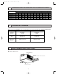
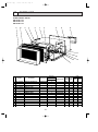
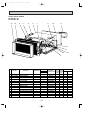
SPLIT-TYPE, AIR CONDITIONERS
No. OC155
REVISED EDITION-B
TECHNICAL & SERVICE MANUAL
Series PE Ceiling Concealed
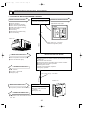
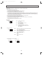
<Indoor unit>
[Model names]
[Service Ref.]
PE-3EJA2.TH
PE-3EJA3.TH
PE-4EJSA2.TH
PE-5EJSA2.TH
PE-6EJSA2.TH
PE-3EJA
PE-4EJSA
PE-5EJSA
PE-6EJSA
PE-3EJA3.TH added in REVISED
EDITION-B.
Please destroy OC155 REVISED
EDITION-A.
This manual does not cover the
following outdoor units.
When servicing them, please refer
to the following service manual and
this manual in a set.
[Service Ref.]
OC152 REVISED EDITION-A
PU-3VJA1.TH, 3YJA1.TH
PU-4VLJSA1.TH, 4YJSA1.TH
PU-5YJSA.TH
PU-6YJSA.TH
OC127 REVISED EDITION-A
PU-3NJA1
PU-4TJSA2
OC199
PU-5TJSA1
PU-6TJSA1
OC206
PU-3VJC.TH, 3YJC.TH
CONTENTS
Indoor unit
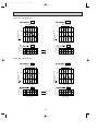
TIMER
TEMP
12
29
11
28
COOL
10
27
DRY
9
26
8
25
7
24
6
23
5
22
4
21
3
20
2
19
1
18
TIMER/TEMP.
POWER
FAN
UP
HIGH
LOW
ON/OFF
MODE
SELECT
FAN
SPEED
DOWN
AUTO
STOP
START
TIMER
MODE
MITSUBISHI ELECTRIC
Remote controller
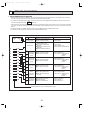
1. COMBINATION OF AND OUTDOOR UNIT···3
2. TECHNICAL CHANGE···························3
3. PART NAMES AND FUNCTIONS··········3
4. SPECIFICATIONS ··································5
5. DATA·······················································9
6. OUTLINES AND DIMENSIONS ···········20
7. WIRING DIAGRAM·······························24
8. REFRIGERANT SYSTEM DIAGRAM ········25
9. OPERATION FLOW-CHART················27
10. MICROPROCESSOR CONTROL ········30
11. TROUBLE SHOOTING·························36
12. DISASSEMBLY PROCEDURE·············39
13. PARTS LIST··········································41
14. OPTIONAL PARTS·······························45
OC155-B--1.qxp
7/26/00 4:42 PM
Page 2
OC155-B--1.qxp
1
7/26/00 4:42 PM
Page 3
COMBINATION OF INDOOR AND OUTDOOR UNITS
Change points
Service Ref.
PE-3EJA2.TH.
PE-3EJA3.TH.
PE-4EJSA2.TH.
PE-5EJSA2.TH.
PE-6EJSA2.TH.
2
3
VJA1.TH YJA1.TH VJC.TH YJC.TH
—
—
—
—
—
—
—
—
—
—
—
—
—
—
—
—
NJA1
—
—
—
Outdoor unit
4
5
6
VLJSA1.TH YJSA1.TH TJSA2 YJSA.TH TJSA1 YJSA.TH TJSA1
—
—
—
—
—
—
—
—
—
—
—
—
—
—
—
—
—
—
—
—
—
—
—
—
—
—
—
—
TECHNICAL CHANGE
Differences with PE-3EJA2.TH / PU-3VJA1.TH, PU-3YJA1.TH (OC155 REVISED EDITION-A)
Change points
PE-3EJA2.TH
PE-3EJA3.TH
COOLING
CAPACITY
24,600 Btu/h
7,200 W
25,600 Btu/h
7,500 W
OUTDOOR
UNIT
PU-3VJA1.TH
PU-3YJA1.TH
PU-3VJC.TH
PU-3YJC.TH
COMPRESSOR
OUTPUT
2.2kW(PU-3YJA1.TH)
2.4kW(PU-3YJC.TH)
3
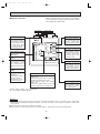
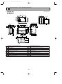
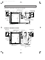
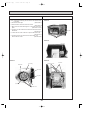
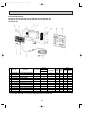
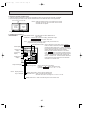
PART NAMES AND FUNCTIONS
● Indoor (Main) Unit
Air intake duct flange
Air intake
(sucks the air inside the room into the unit)
Air outlet
Air outlet duct flange
3
OC155-B--1.qxp
7/27/00 8:48 AM
Page 4
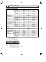
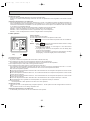
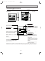
● Remote controller
Settings remain in effect until changed. Air conditioner
can be operated by simply pushing ON /OFF button
once settings have been made.
Display Panel
Operating Panel
TIMER / TEMP.
ON / OFF button
This button is used to
change between display of
room temperature and display of remaining timer during "AUTO STOP" operation. Green lamps light in
selected display mode.
Pushing button starts operation. Pushing again stops
operation.
Green lamp
remains lit during operation
Lamps display remaining timer time or room
temperature.
Remaining timer time
display
TIMER
TEMP
12
29
11
28
COOL
10
27
DRY
9
26
FAN
8
25
7
24
6
23
5
22
4
21
3
20
2
19
1
18
TIMER/TEMP.
UP
POWER
HIGH
LOW
ON/OFF
MODE
SELECT
FAN
SPEED
DOWN
Lamps
indicate
time
remaining until timer stops
timed operation. Green
lamps corresponding to
remaining number of hours
light.
AUTO
STOP
START
TIMER
MODE
This button is used to
change between cooling,
ventilation and DRY operation modes. One of three
green lamps lights to indicate mode in effect.
FAN SPEED button
MITSUBISHI ELECTRIC
Room Temperature
display
Lamps display temperature
settings and actual room
temperatures.
● Temperature settings;
Green lamps light.
● Temperature in room;
Green lamps flash.
MODE SELECT button
This button is used to
change between low and
high fan speeds. One of
two green lamps lights to
indicate fan speed in effect.
UP and DOWN buttons
● Temperature control (While "TEMP" green
lamps is lit.)
Use UP and DOWN buttons to set desired
temperature between 18 and 29°C.
● Timed operation (While green "TIMER"
lamp is lit.)
Use UP and DOWN buttons to set timed
operation between one and twelve hours.
TIMER MODE button
Used for selecting timed
starting or stopping. Green
lamps lights to indicate
timer mode selected.
(Example display readings are for explanations
only ; actual display readings will differ.)
Attention :
● Pushing UP and Down buttons together for more than two seconds will initiate "trial run" or "inspection" mode. Avoid pushing
these buttons simultaneously during normal operation. Push ON / OFF button to cancel trial run or inspection mode if initiated by accident.
● All green lamps turn off when air conditioner is stopped.
● Avoid operation of buttons with fingernails or other sharp objects. Sharp objects may scratch operating panel.
4
OC155-B--1.qxp
7/26/00 4:43 PM
4
Page 5
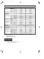
SPECIFICATIONS
1. STANDARD SPECIFICATIONS
Service Ref.
Item
50Hz
Cooling capacity W1
60Hz
Cooling capacity W2
60Hz
Total input (50/60Hz) W3
Service Ref.
External finish
Fan motor output
50Hz
INDOOR UNIT
PE-3EJA 2.TH
7,200
24,600
8,100
27,600
6,700
23,000
3.41 / 3.76
PE-3EJA 2.TH
kW
m3/min
CFM
m3/min
CFM
Pa (mmAq)
Pa (mmAq)
0.2
19 - 22
671 - 777
22 - 26
777 - 918
49 (5)
69 (7)
PE-4EJSA 2.TH
9,800
33,400
10,900
37,200
9,400
32,000
3.59 / 4.69
PE-4EJSA 2.TH
Galvanized sheets
Airflow Lo - High
OUTDOOR UNIT
W
Btu/h
W
Btu/h
W
Btu/h
kW
60Hz
0.3
27 - 34
953 - 1,200
27 - 34
953 - 1,200
62 (6.35)
62 (6.35)
Remote controller & built-in
46 - 48
54 - 58
48 - 50
54 - 58
R1
R1
785 (31)
1,055 (41-1/2)
690 (27-1/6)
690 (27-1/6)
428 (16-7/8)
428 (16-7/8)
46 (101)
58 (128)
W7 PU-3JA type
W7 PU-4JSA type
Munsell 5Y 7/1
Capillary tube
2.2
2.7
W6
32 / 38
32 / 38
0.085
0.065 + 0.065
50 (1,765)
95 (3,352)
50 (1,765)
95 (3,352)
52 / 53
54 / 55
870 (34-1/4)
870 (34-1/4)
295 + 24 (11-5/8 add 1)
850 (33-7/16)
1,258 (49-1/2)
73 (161)
94 (207)
Ex. static pressure at
50Hz
Hi - notch
60Hz
Operation control & thermostat
50Hz
dB
Noise level Low - High W5
60Hz
dB
in.
Unit drain thread
W
mm (in.)
D
mm (in.)
Dimensions
H
mm (in.)
kg (lbs)
Weight
Service Ref.
External finish
Refrigerant (R-22) control
Compressor output
kW
Protection devices
Crankcase heater W4 50/60Hz
W
Fan motor output
kW
50Hz m3/min(CFM)
Airflow
60Hz m3/min(CFM)
50/60Hz
Noise level W5
dB
W
mm (in.)
D
Dimensions
mm (in.)
H
mm (in.)
Weight
kg (lbs)
NOTE : W1 Rating conditions (JIS B 8616)
Indoor : D.B. 27°C (80°F), W.B.19°C (86°F)
Outdoor : D.B. 35°C (95°F), W.B. 24°C (75°F)
NOTE : W2 Rating conditions (SSA 385, 386)
Indoor : D.B. 29°C (84°F), W.B.19°C (86°F)
Outdoor : D.B. 46°C (115°F), W.B. 24°C (75°F)
NOTE : W3 Total input based on indicated voltage.
(Indoor / Outdoor)
PE-4EJSA2.TH
Service Ref. PE-3EJA2.TH
1ph 220V / 1ph 220V 1ph 220V / 3ph 380V
50Hz
1ph 220V / 1ph 220V 1ph 220V / 3ph 220V
60Hz
Rating conditions (JIS B 8616)
NOTE : W4 Capacity of crankcase heater (W) based on 220 volts.
NOTE : W5 Noise level is measured in an unacoustic room based on JIS conditions.
NOTE : W6 V , N ···Inner thermostat, HP switch, LP switch
VL ···Inner thermostat, HP switch, LP switch, thermal switch.
T, Y···Thermal switch, Reversed - phase protector, HP switch, LP switch
NOTE : W7 PU-3JA type···PU-3VJA1.TH, 3YJA1.TH, 3NJA1
PU-4JSA type···PU-4VLJSA1.TH, 4YJSA1.TH, 4TJSA2
5
OC155-B--1.qxp
7/26/00 4:43 PM
Page 6
Service Ref.
Item
50Hz
Cooling capacity W1
60Hz
Cooling capacity W2
60Hz
Total input (50/60Hz) W3
Service Ref.
External finish
Fan motor output
50Hz
OUTDOOR UNIT
INDOOR UNIT
Airflow Lo - High
60Hz
W
Btu/h
W
Btu/h
W
Btu/h
kW
kW
m3/min
CFM
m3/min
CFM
Pa (mmAq)
Pa (mmAq)
Ex. static pressure at
50Hz
Hi - notch
60Hz
Operation control & thermostat
50Hz
dB
Noise level Low - High W5
60Hz
dB
in.
Unit drain thread
W
mm (in.)
D
mm (in.)
Dimensions
H
mm (in.)
kg (lbs)
Weight
Service Ref.
External finish
Refrigerant (R-22) control
Compressor output
kW
Protection devices
Crankcase heater
50/60Hz
W
Fan motor output
kW
50Hz m3/min(CFM)
Airflow
60Hz m3/min(CFM)
Noise level W5
50/60Hz
dB
W
mm (in.)
Dimensions
D
mm (in.)
H
mm (in.)
Weight
kg (lbs)
PE-5EJSA2.TH
12,100
41,300
13,500
46,100
11,000
37,500
5.10 / 6.06
PE-5EJSA2.TH
Galvanized sheets
0.4
0.4
34 - 42
34 - 42
1,200 - 1,482
1,200 - 1,482
34 - 42
34 - 42
1,200 - 1,482
1,200 - 1,482
62 (6.35)
62 (6.35)
62 (6.35)
62 (6.35)
Remote controller & built-in
54 - 58
54 - 58
54 - 58
54 - 58
R1
R1
1,255 (49-7/16)
1,255 (49-7/16)
690 (27-1/6)
690 (27-1/6)
428 (16-7/8)
428 (16-7/8)
72 (159)
72 (159)
PU-5YJSA.TH, 5TJSA1
PU-6YJSA.TH, 6TJSA1
Munsell 5Y 7/1
Capillary tube
3.5
4.2/4.0
W6
W6
–
–
0.10 + 0.10
0.10 + 0.10
100(3,530)
100(3,530)
100(3,530)
100(3,530)
55 / 55
56/56
970 (38-3/16)
970 (38-3/16)
345 + 24 (13-9/16 add 1)
1,258 (49-1/2)
1,258 (49-1/2)
114 (282)
117 (313)
NOTE : W1 Rating conditions (JIS B 8616)
Indoor : D.B. 27°C (80°F), W.B. 19°C (86°F)
Outdoor : D.B. 35°C (95°F), W.B. 24°C (75°F)
NOTE : W2 Rating conditions (SSA 385, 386)
Indoor : D.B. 29°C (84°F), W.B. 19°C (86°F)
Outdoor : D.B. 46°C (115°F), W.B. 24°C (75°F)
NOTE : W3 Total input based on indicated voltage.
(Indoor / Outdoor)
Service Ref. PE-5/6EJSA2.TH
50Hz
60Hz
PE-6EJSA2.TH
14,000
47,800
15,200
51,900
13,400
45,700
5.65 / 6.58
PE-6EJSA2.TH
1ph 220V / 3ph 380V
1ph 220V / 3ph 220V
Rating conditions (JIS B 8616)
NOTE : W4 Capacity of crankcase heater (W) based on 220 volts.
NOTE : W5 Noise level is measured in an unacoustic room based on JIS conditions.
NOTE : W6 Y : Inner thermostat, HP switch, Thermal switch
T : Inner thermostat, HP switch, LP switch, Thermal switch
6
OC155-B--1.qxp
7/26/00 4:43 PM
Page 7
Service Ref.
Item
50Hz
Cooling capacity W1
60Hz
Cooling capacity W2
60Hz
Total input (50/60Hz) W3
Service Ref.
External finish
Fan motor output
50Hz
OUTDOOR UNIT
INDOOR UNIT
Airflow Lo - High
60Hz
PE-3EJA 3.TH
7,500
25,600
8,100
27,600
6,700
23,000
3.41 / 3.76
PE-3EJA 3.TH
Galvanized sheets
0.2
19 - 22
671 - 777
22 - 26
777 - 918
49 (5)
69 (7)
Remote controller & built-in
46 - 48
48 - 50
R1
785 (31)
690 (27-1/6)
428 (16-7/8)
46 (101)
PU-3VJC.TH, 3YJC.TH, 3NJA1
Munsell 5Y 7/1
Capillary tube
(V)2.2, (Y)2.4 / (N)2.2
W6
32 / 38
0.085
50 (1,765)
50 (1,765)
52 / 53
870 (34-1/4)
295 + 24 (11-5/8 add 1)
850 (33-7/16)
73 (161)
W
Btu/h
W
Btu/h
W
Btu/h
kW
kW
m3/min
CFM
m3/min
CFM
Pa (mmAq)
Pa (mmAq)
Ex. static pressure at
50Hz
Hi - notch
60Hz
Operation control & thermostat
50Hz
dB
Noise level Low - High W5
60Hz
dB
in.
Unit drain thread
W
mm (in.)
D
mm (in.)
Dimensions
H
mm (in.)
kg (lbs)
Weight
Service Ref.
External finish
Refrigerant (R-22) control
kW
Compressor output
Protection devices
W
Crankcase heater W4 50/60Hz
kW
Fan motor output
50Hz m3/min(CFM)
Airflow
60Hz m3/min(CFM)
50/60Hz
Noise level W5
dB
W
mm (in.)
D
Dimensions
mm (in.)
H
mm (in.)
Weight
kg (lbs)
NOTE : W1 Rating conditions (JIS B 8616)
Indoor : D.B. 27°C (80°F), W.B. 19°C (86°F)
Outdoor : D.B. 35°C (95°F), W.B. 24°C (75°F)
NOTE : W2 Rating conditions (SSA 385, 386)
Indoor : D.B. 29°C (84°F), W.B. 19°C (86°F)
Outdoor : D.B. 46°C (115°F), W.B. 24°C (75°F)
NOTE : W3 Total input based on indicated voltage.
(Indoor / Outdoor)
Service Ref.
PE - 3EJA 3.TH
50Hz
1ph 220V / 1ph 220V, 3ph 380V
1ph 220V / 1ph 220V
60Hz
Rating conditions (JIS B 8616)
NOTE : W4 Capacity of crankcase heater (W) based on 220 volts.
NOTE : W5 Noise level is measured in an unacoustic room based on JIS conditions.
NOTE : W6 V , N ···Inner thermostat, HP switch, LP switch
Y···Thermal switch, Reversed - phase protector, HP switch, LP switch
7
OC155-B--1.qxp
7/26/00 4:43 PM
Page 8
2. POWER SUPPLY & MODEL NAMES
Power supply
50Hz
60Hz
1ph.
3ph.
1ph.
3ph.
Service Ref.(Indoor unit)
220, 230, 240V
380/220, 400/230, 415/240V
220V
220V
PE - 3EJA 2.TH
PU-3VJA1.TH
PU-3YJA1.TH
PU-3NJA1
—
Service Ref.(Outdoor unit)
PE - 3EJA 3.TH PE - 4EJSA 2.TH PE - 5EJSA 2.TH PE - 6EJSA 2.TH
PU-3VJC.TH
PU-4VLJSA1.TH
—
—
PU-3YJC.TH
PU-5YJSA.TH
PU-4YJSA1.TH
PU-6YJSA.TH
PU-3NJA1
—
—
—
PU-5TJSA1
PU-4TJSA2
—
PU-6TJSA1
NOTE : 1. Power supply key N ········1ph, 220V, 60Hz
V (L) ···1ph, 220, 230, 240V, 50Hz
Y ··· 3ph, 380 / 220, 400 / 230,
T ·········3ph, 220V, 60Hz
415 / 240V, 50Hz, 4wires
2. Primary power supplies for all indoor units are single - phase.
3. ELECTRICAL SPECIFICATIONS
Rating conditions — JIS B 8616
Indoor : D.B. 27°C (80°F), W.B. 19°C (66°F)
Outdoor : D.B. 35°C (95°F), W.B. 24°C (75°F)
Series PE Indoor Unit (Single Phase)
V : 220V 50Hz
V : 230V 50Hz
V : 240V 50Hz
N : 220V 60Hz
PE-3EJA2.TH
PE-3EJA2.TH
PE-3EJA2.TH
PE-3EJA2.TH
PE-3EJA3.TH PE-4EJSA2.TH PE-3EJA3.TH PE-4EJSA2.TH PE-3EJA3.TH PE-4EJSA2.TH PE-3EJA3.TH PE-4EJSA2.TH
A
1.41
1.07
1.07
1.40
1.07
1.39
1.47
1.95
kW
0.30
0.23
0.24
0.31
0.25
0.32
0.32
0.42
A
2.6
2.4
2.5
2.6
2.6
2.6
2.1
2.6
PU-4
PU-3
PU-3
PU-4
PU-3
PU-4
PU-3
PU-4
Power supply (1 phase)
Service Ref.
Current
Input
Starting current
Outdoor unit
Power supply (1 phase)
Y : 220V 50Hz
Y : 230V 50Hz
Y : 240V 50Hz
T : 220V 60Hz
Service Ref.
PE-5EJSA2.TH PE-6EJSA2.TH PE-5EJSA2.TH PE-6EJSA2.TH PE-5EJSA2.TH PE-6EJSA2.TH PE-5EJSA2.TH PE-6EJSA2.TH
Current
2.50
2.50
2.53
2.53
2.58
2.58
1.99
1.99
A
Input
0.54
0.54
0.57
0.57
0.60
0.60
0.43
0.43
kW
Starting current
4.1
4.1
4.1
4.1
4.1
4.1
3.1
3.1
A
Outdoor unit
PU-5
PU-6
PU-5
PU-6
PU-5
PU-6
PU-5
PU-6
8
OC155-B--1.qxp
7/26/00 4:43 PM
5
Page 9
DATA
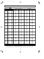
1. PERFORMANCE DATA
Cooling capacity 50Hz
Service Ref.
Temperature
Outdoor D.B.
21°C
(69.8°F)
25°C
(77°F)
30°C
(86°F)
32.2°C
(90°F)
35°C
(95°F)
40°C
(104°F)
40.6°C
(105°F)
45°C
(113°F)
46°C
(115°F)
50°C
(122°F)
52°C
(125.5°F)
PE-3EJA2.TH
16°C
18°C
19°C
19.4°C
20°C
22°C
16°C
18°C
19°C
19.4°C
20°C
22°C
16°C
18°C
19°C
19.4°C
20°C
22°C
16°C
18°C
19°C
19.4°C
20°C
22°C
16°C
18°C
19°C
19.4°C
20°C
22°C
16°C
18°C
19°C
19.4°C
20°C
22°C
16°C
18°C
19°C
19.4°C
20°C
22°C
16°C
18°C
19°C
19.4°C
20°C
22°C
16°C
18°C
19°C
19.4°C
20°C
22°C
16°C
18°C
19°C
19.4°C
20°C
22°C
16°C
18°C
19°C
19.4°C
20°C
22°C
Evaporator airflow (m3/min)
Bypass factors
S.H.F. at rating conditions
Notes :
T.C.
7.2
7.7
7.9
8.0
8.2
8.7
7.1
7.5
7.8
7.9
8.0
8.5
6.8
7.3
7.5
7.6
7.7
8.2
6.7
7.1
7.4
7.5
7.6
8.1
6.5
7.0
7.2
7.3
7.4
7.9
6.2
6.7
6.9
7.0
7.1
7.6
6.2
6.6
6.9
6.9
7.1
7.6
5.9
6.4
6.6
6.7
6.8
7.3
5.9
6.3
6.5
6.6
6.7
7.2
5.6
6.0
6.2
6.3
6.5
6.9
5.5
5.9
6.1
6.2
6.3
6.8
Indoor D.B.
(60.8°F)
(64.4°F)
(66.2°F)
(67°F)
(68°F)
(71.6°F)
(60.8°F)
(64.4°F)
(66.2°F)
(67°F)
(68°F)
(71.6°F)
(60.8°F)
(64.4°F)
(66.2°F)
(67°F)
(68°F)
(71.6°F)
(60.8°F)
(64.4°F)
(66.2°F)
(67°F)
(68°F)
(71.6°F)
(60.8°F)
(64.4°F)
(66.2°F)
(67°F)
(68°F)
(71.6°F)
(60.8°F)
(64.4°F)
(66.2°F)
(67°F)
(68°F)
(71.6°F)
(60.8°F)
(64.4°F)
(66.2°F)
(67°F)
(68°F)
(71.6°F)
(60.8°F)
(64.4°F)
(66.2°F)
(67°F)
(68°F)
(71.6°F)
(60.8°F)
(64.4°F)
(66.2°F)
(67°F)
(68°F)
(71.6°F)
(60.8°F)
(64.4°F)
(66.2°F)
(67°F)
(68°F)
(71.6°F)
(60.8°F)
(64.4°F)
(66.2°F)
(67°F)
(68°F)
(71.6°F)
PE-4EJSA2.TH
C.F.
(T.I.)
0.81
0.82
0.83
0.83
0.84
0.86
0.84
0.85
0.86
0.86
0.87
0.89
0.90
0.92
0.93
0.93
0.94
0.96
0.93
0.95
0.96
0.97
0.97
0.99
0.96
0.99
1.00
1.00
1.01
1.04
1.03
1.06
1.07
1.08
1.08
1.11
1.04
1.06
1.08
1.08
1.09
1.12
1.10
1.12
1.14
1.15
1.16
1.20
1.11
1.14
1.15
1.16
1.17
1.21
1.16
1.19
1.21
1.22
1.23
1.28
1.19
1.22
1.24
1.25
1.26
1.31
T.C.
9.8
10.5
10.8
10.9
11.1
11.8
9.6
10.2
10.6
10.7
10.9
11.6
9.3
9.9
10.2
10.3
10.5
11.2
9.1
9.7
10.0
10.2
10.3
11.0
8.9
9.5
9.8
10.1
10.1
10.8
8.5
9.1
9.4
9.5
9.7
10.3
8.4
9.0
9.3
9.5
9.6
10.3
8.1
8.6
8.9
9.1
9.3
9.9
8.0
8.6
8.9
9.0
9.2
9.8
7.6
8.2
8.5
8.6
8.8
9.4
7.4
8.0
8.3
8.4
8.6
9.2
22
0.26
0.69
.
3
1. T.C : Total capacity ( ✕ 10 W) ... (Btu / h) =. (W) ✕ 3.4, (kcal / h) = (W) ✕ 0.86
C.F (T.I.) : Correction factors of Total input (Indoor unit input + Outdoor unit input)
2. (°F) = 32 + 9 / 5 (°C)
Lower limit ... Indoor : D.B. 21°C (70°F), W.B. 15.5°C (60°F),
3. Guaranteed operating range (cooling)
Upper limit ... Indoor : D.B. 35°C (95°F), W.B. 22.5°C (72.5°F),
{
9
34
0.21
0.76
Outdoor : D.B. 21°C (70°F)
Outdoor : D.B. 52°C (125.5°F)
WVL ... Outdoor : D.B. 46°C (115°F)
C.F.
(T.I.)
0.81
0.82
0.83
0.83
0.84
0.86
0.84
0.85
0.86
0.86
0.87
0.89
0.90
0.92
0.93
0.93
0.94
0.96
0.93
0.95
0.96
0.97
0.97
0.99
0.96
0.99
1.00
1.00
1.01
1.04
1.03
1.06
1.07
1.08
1.08
1.11
1.04
1.06
1.08
1.08
1.09
1.12
1.10
1.12
1.14
1.15
1.16
1.20
1.11
1.14
1.15
1.16
1.17
1.21
1.16
1.19
1.21
1.22
1.23
1.28
1.19
1.22
1.24
1.25
1.26
1.31
OC155-B--1.qxp
7/26/00 4:43 PM
Page 10
Cooling capacity 50Hz
Service Ref.
Temperature
Outdoor D.B.
21°C
(69.8°F)
25°C
(77°F)
30°C
(86°F)
32.2°C
(90°F)
35°C
(95°F)
40°C
(104°F)
40.6°C
(105°F)
45°C
(113°F)
46°C
(115°F)
50°C
(122°F)
52°C
(125.5°F)
PE-3EJA3.TH
T.C.
7.5
8.0
8.3
8.4
8.5
9.0
7.4
7.8
8.1
8.2
8.4
8.9
7.1
7.6
7.8
7.9
8.1
8.6
7.0
7.4
7.7
7.8
7.9
8.4
6.8
7.3
7.5
7.6
7.7
8.3
6.5
6.9
7.2
7.3
7.4
7.9
6.5
6.9
7.1
7.2
7.4
7.9
6.2
6.6
6.8
6.9
7.1
7.6
6.1
6.5
6.8
6.9
7.0
7.5
5.8
6.3
6.5
6.6
6.7
7.2
5.7
6.1
6.4
6.5
6.6
7.1
Indoor D.B.
16°C
18°C
19°C
19.4°C
20°C
22°C
16°C
18°C
19°C
19.4°C
20°C
22°C
16°C
18°C
19°C
19.4°C
20°C
22°C
16°C
18°C
19°C
19.4°C
20°C
22°C
16°C
18°C
19°C
19.4°C
20°C
22°C
16°C
18°C
19°C
19.4°C
20°C
22°C
16°C
18°C
19°C
19.4°C
20°C
22°C
16°C
18°C
19°C
19.4°C
20°C
22°C
16°C
18°C
19°C
19.4°C
20°C
22°C
16°C
18°C
19°C
19.4°C
20°C
22°C
16°C
18°C
19°C
19.4°C
20°C
22°C
(60.8°F)
(64.4°F)
(66.2°F)
(67°F)
(68°F)
(71.6°F)
(60.8°F)
(64.4°F)
(66.2°F)
(67°F)
(68°F)
(71.6°F)
(60.8°F)
(64.4°F)
(66.2°F)
(67°F)
(68°F)
(71.6°F)
(60.8°F)
(64.4°F)
(66.2°F)
(67°F)
(68°F)
(71.6°F)
(60.8°F)
(64.4°F)
(66.2°F)
(67°F)
(68°F)
(71.6°F)
(60.8°F)
(64.4°F)
(66.2°F)
(67°F)
(68°F)
(71.6°F)
(60.8°F)
(64.4°F)
(66.2°F)
(67°F)
(68°F)
(71.6°F)
(60.8°F)
(64.4°F)
(66.2°F)
(67°F)
(68°F)
(71.6°F)
(60.8°F)
(64.4°F)
(66.2°F)
(67°F)
(68°F)
(71.6°F)
(60.8°F)
(64.4°F)
(66.2°F)
(67°F)
(68°F)
(71.6°F)
(60.8°F)
(64.4°F)
(66.2°F)
(67°F)
(68°F)
(71.6°F)
Evaporator airflow (m3/min)
Bypass factors
S.H.F. at rating conditions
Notes :
22
0.26
0.72
C.F.
(T.I.)
0.81
0.82
0.83
0.83
0.84
0.86
0.84
0.85
0.86
0.86
0.87
0.89
0.90
0.92
0.93
0.93
0.94
0.96
0.93
0.95
0.96
0.97
0.97
0.99
0.96
0.99
1.00
1.00
1.01
1.04
1.03
1.06
1.07
1.08
1.08
1.11
1.04
1.06
1.08
1.08
1.09
1.12
1.10
1.12
1.14
1.15
1.16
1.20
1.11
1.14
1.15
1.16
1.17
1.21
1.16
1.19
1.21
1.22
1.23
1.28
1.19
1.22
1.24
1.25
1.26
1.31
.
3
1. T.C : Total capacity ( ✕ 10 W) ... (Btu / h) =. (W) ✕ 3.4, (kcal / h) = (W) ✕ 0.86
C.F (T.I.) : Correction factors of Total input (Indoor unit input + Outdoor unit input)
2. (°F) = 32 + 9 / 5 (°C)
Lower limit ... Indoor : D.B. 21°C (70°F), W.B. 15.5°C (60°F),
Outdoor : D.B. 21°C (70°F)
3. Guaranteed operating range (cooling)
Upper limit ... Indoor : D.B. 35°C (95°F), W.B. 22.5°C (72.5°F), Outdoor : D.B. 52°C (125.5°F)
{
10
OC155-B--1.qxp
7/26/00 4:43 PM
Page 11
Cooling capacity 50Hz
Service Ref.
Temperature
Outdoor D.B.
21°C
(69.8°F)
25°C
(77°F)
30°C
(86°F)
32.2°C
(90°F)
35°C
(95°F)
40°C
(104°F)
40.6°C
(105°F)
45°C
(113°F)
46°C
(115°F)
50°C
(122°F)
52°C
(125.5°F)
PE-5EJSA2.TH
Indoor D.B.
16°C
18°C
19°C
19.4°C
20°C
22°C
16°C
18°C
19°C
19.4°C
20°C
22°C
16°C
18°C
19°C
19.4°C
20°C
22°C
16°C
18°C
19°C
19.4°C
20°C
22°C
16°C
18°C
19°C
19.4°C
20°C
22°C
16°C
18°C
19°C
19.4°C
20°C
22°C
16°C
18°C
19°C
19.4°C
20°C
22°C
16°C
18°C
19°C
19.4°C
20°C
22°C
16°C
18°C
19°C
19.4°C
20°C
22°C
16°C
18°C
19°C
19.4°C
20°C
22°C
16°C
18°C
19°C
19.4°C
20°C
22°C
Evaporator airflow (m3/min)
Bypass factors
S.H.F. at rating conditions
(60.8°F)
(64.4°F)
(66.2°F)
(67°F)
(68°F)
(71.6°F)
(60.8°F)
(64.4°F)
(66.2°F)
(67°F)
(68°F)
(71.6°F)
(60.8°F)
(64.4°F)
(66.2°F)
(67°F)
(68°F)
(71.6°F)
(60.8°F)
(64.4°F)
(66.2°F)
(67°F)
(68°F)
(71.6°F)
(60.8°F)
(64.4°F)
(66.2°F)
(67°F)
(68°F)
(71.6°F)
(60.8°F)
(64.4°F)
(66.2°F)
(67°F)
(68°F)
(71.6°F)
(60.8°F)
(64.4°F)
(66.2°F)
(67°F)
(68°F)
(71.6°F)
(60.8°F)
(64.4°F)
(66.2°F)
(67°F)
(68°F)
(71.6°F)
(60.8°F)
(64.4°F)
(66.2°F)
(67°F)
(68°F)
(71.6°F)
(60.8°F)
(64.4°F)
(66.2°F)
(67°F)
(68°F)
(71.6°F)
(60.8°F)
(64.4°F)
(66.2°F)
(67°F)
(68°F)
(71.6°F)
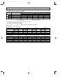
T.C.
12.1
12.9
13.3
13.5
13.7
14.6
11.9
12.7
13.1
13.2
13.5
14.3
11.4
12.2
12.6
12.8
13.0
13.8
11.2
12.0
12.4
12.5
12.8
13.6
11.0
11.7
12.1
12.3
12.5
13.3
10.5
11.2
11.6
11.7
12.0
12.8
10.4
11.1
11.5
11.7
11.9
12.7
10.0
10.7
11.0
11.2
11.4
12.2
9.9
10.6
10.9
11.0
11.2
12.1
8.9
9.6
9.9
10.0
10.3
10.6
7.9
8.5
8.8
8.9
9.1
9.4
42
0.18
0.82
C.F.
(T.I.)
0.81
0.82
0.83
0.83
0.84
0.86
0.84
0.85
0.86
0.86
0.87
0.89
0.90
0.92
0.93
0.93
0.94
0.96
0.93
0.95
0.96
0.97
0.97
0.99
0.96
0.99
1.00
1.00
1.01
1.04
1.03
1.06
1.07
1.08
1.08
1.11
1.04
1.06
1.08
1.08
1.09
1.12
1.10
1.12
1.14
1.15
1.16
1.20
1.11
1.14
1.15
1.16
1.17
1.21
1.16
1.19
1.21
1.22
1.23
1.28
1.19
1.22
1.24
1.25
1.26
1.31
PE-6EJSA2.TH
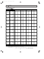
T.C.
14.1
15.0
15.4
15.6
15.9
16.8
13.7
14.6
15.1
15.3
15.6
16.6
13.2
14.1
14.6
14.8
15.0
16.0
13.0
13.9
14.3
14.5
14.8
15.7
12.7
13.5
14.0
14.2
14.5
15.4
12.1
13.0
13.4
13.6
13.8
14.8
12.1
12.9
13.3
13.5
13.8
14.7
11.5
12.4
12.8
13.0
13.2
14.1
11.4
12.2
12.6
12.7
13.0
14.0
10.3
11.1
11.5
11.6
11.9
12.3
9.1
9.8
10.2
10.3
10.5
10.9
42
0.16
0.77
.
3
Notes : 1. T.C : Total capacity ( ✕ 10 W) ... (Btu / h) =. (W) ✕ 3.4, (kcal / h) = (W) ✕ 0.86
C.F (T.I.) : Correction factors of Total input (Indoor unit input + Outdoor unit input)
2. (°F) = 32 + 9 / 5 (°C)
Lower limit ... Indoor : D.B. 21°C (70°F), W.B. 15.5°C (60°F),
Outdoor : D.B. 21°C (70°F)
3. Guaranteed operating range (cooling)
Upper limit ... Indoor : D.B. 35°C (95°F), W.B. 22.5°C (72.5°F), Outdoor : D.B. 52°C (125.5°F)
WVL ... Outdoor : D.B. 46°C (115°F)
{
11
C.F.
(T.I.)
0.81
0.82
0.83
0.83
0.84
0.86
0.84
0.85
0.86
0.86
0.87
0.89
0.90
0.92
0.93
0.93
0.94
0.96
0.93
0.95
0.96
0.97
0.97
0.99
0.96
0.99
1.00
1.00
1.01
1.04
1.03
1.06
1.07
1.08
1.08
1.11
1.04
1.06
1.08
1.08
1.09
1.12
1.10
1.12
1.14
1.15
1.16
1.20
1.11
1.14
1.15
1.16
1.17
1.21
1.16
1.19
1.21
1.22
1.23
1.28
1.19
1.22
1.24
1.25
1.26
1.31
OC155-B--1.qxp
7/26/00 4:43 PM
Page 12
Cooling capacity 60Hz
Service Ref.
Temperature
Outdoor D.B.
21°C
(69.8°F)
25°C
(77°F)
30°C
(86°F)
32.2°C
(90°F)
35°C
(95°F)
40°C
(104°F)
40.6°C
(105°F)
45°C
(113°F)
46°C
(115°F)
50°C
(122°F)
52°C
(125.5°F)
Indoor D.B.
16°C
18°C
19°C
19.4°C
20°C
22°C
16°C
18°C
19°C
19.4°C
20°C
22°C
16°C
18°C
19°C
19.4°C
20°C
22°C
16°C
18°C
19°C
19.4°C
20°C
22°C
16°C
18°C
19°C
19.4°C
20°C
22°C
16°C
18°C
19°C
19.4°C
20°C
22°C
16°C
18°C
19°C
19.4°C
20°C
22°C
16°C
18°C
19°C
19.4°C
20°C
22°C
16°C
18°C
19°C
19.4°C
20°C
22°C
16°C
18°C
19°C
19.4°C
20°C
22°C
16°C
18°C
19°C
19.4°C
20°C
22°C
Evaporator airflow (m3/min)
Bypass factors
S.H.F. at rating conditions
Notes :
PE-3EJA2.TH, PE-3EJA3.TH
C.F.
T.C.
(T.I.)
8.1
0.81
8.7
0.82
8.9
0.83
9.0
0.83
9.2
0.84
9.7
0.86
7.9
0.84
8.5
0.85
8.7
0.86
8.9
0.86
9.0
0.87
9.6
0.89
7.7
0.90
8.2
0.92
8.4
0.93
8.5
0.93
8.7
0.94
9.3
0.96
7.5
0.93
8.0
0.95
8.3
0.96
8.4
0.97
8.6
0.97
9.1
0.99
7.3
0.96
7.8
0.99
8.1
1.00
8.2
1.00
8.4
1.01
8.9
1.04
7.0
1.03
7.5
1.06
7.8
1.07
7.9
1.08
8.0
1.08
8.5
1.11
7.0
1.04
7.5
1.06
7.8
1.08
7.9
1.08
8.0
1.09
8.5
1.12
6.7
1.10
7.5
1.12
7.4
1.14
7.5
1.15
8.0
1.16
8.2
1.20
6.6
1.11
7.1
1.14
7.3
1.15
7.4
1.16
7.6
1.17
8.1
1.21
6.3
1.16
6.8
1.19
7.0
1.21
7.1
1.22
7.3
1.23
7.8
1.28
6.2
1.19
6.6
1.22
6.9
1.24
7.0
1.25
7.1
1.26
7.6
1.31
26
0.35
0.67
(60.8°F)
(64.4°F)
(66.2°F)
(67°F)
(68°F)
(71.6°F)
(60.8°F)
(64.4°F)
(66.2°F)
(67°F)
(68°F)
(71.6°F)
(60.8°F)
(64.4°F)
(66.2°F)
(67°F)
(68°F)
(71.6°F)
(60.8°F)
(64.4°F)
(66.2°F)
(67°F)
(68°F)
(71.6°F)
(60.8°F)
(64.4°F)
(66.2°F)
(67°F)
(68°F)
(71.6°F)
(60.8°F)
(64.4°F)
(66.2°F)
(67°F)
(68°F)
(71.6°F)
(60.8°F)
(64.4°F)
(66.2°F)
(67°F)
(68°F)
(71.6°F)
(60.8°F)
(64.4°F)
(66.2°F)
(67°F)
(68°F)
(71.6°F)
(60.8°F)
(64.4°F)
(66.2°F)
(67°F)
(68°F)
(71.6°F)
(60.8°F)
(64.4°F)
(66.2°F)
(67°F)
(68°F)
(71.6°F)
(60.8°F)
(64.4°F)
(66.2°F)
(67°F)
(68°F)
(71.6°F)
PE-4EJSA2.TH
T.C.
10.9
11.7
12.0
12.2
12.4
13.1
10.7
11.4
11.8
11.9
12.1
12.9
10.3
11.0
11.3
11.5
11.7
12.5
10.1
10.8
11.2
11.3
11.5
12.3
9.9
10.5
10.9
11.0
11.3
12.0
9.4
10.1
10.4
10.6
10.8
11.5
9.4
10.0
10.4
10.5
10.7
11.4
9.0
9.6
10.0
10.1
10.3
11.0
8.9
9.5
9.9
10.0
10.2
10.9
8.5
9.1
9.5
9.6
9.8
10.5
8.3
8.9
9.2
9.4
9.6
10.3
34
0.23
0.74
C.F.
(T.I.)
0.81
0.82
0.83
0.83
0.84
0.86
0.84
0.85
0.86
0.86
0.87
0.89
0.90
0.92
0.93
0.93
0.94
0.96
0.95
0.96
0.97
0.97
1.00
0.99
0.96
0.99
1.00
1.00
1.01
1.04
1.03
1.06
1.07
1.08
1.08
1.11
1.04
1.06
1.08
1.08
1.09
1.12
1.10
1.12
1.14
1.15
1.16
1.20
1.11
1.14
1.15
1.16
1.17
1.21
1.16
1.19
1.21
1.22
1.23
1.28
1.19
1.22
1.24
1.25
1.26
1.31
.
3
1. T.C : Total capacity ( ✕ 10 W) ... (Btu / h) =. (W) ✕ 3.4, (kcal / h) = (W) ✕ 0.86
C.F (T.I) : Correction factors of Total input (Indoor unit input + Outdoor unit input)
2. (°F) = 32 + 9 / 5 (°C)
Lower limit ... Indoor : D.B. 21°C (70°F), W.B. 15.5°C (60°F),
Outdoor : D.B. 21°C (70°F)
3. Guaranteed operating range (cooling)
Upper limit ... Indoor : D.B. 35°C (95°F), W.B. 22.5°C (72.5°F), Outdoor : D.B. 52°C (125.5°F)
{
12
OC155-B--1.qxp
7/26/00 4:43 PM
Page 13
Cooling capacity 60Hz
Service Ref.
Temperature
Outdoor D.B.
21°C
(69.8°F)
25°C
(77°F)
30°C
(86°F)
32.2°C
(90°F)
35°C
(95°F)
40°C
(104°F)
40.6°C
(105°F)
45°C
(113°F)
46°C
(115°F)
50°C
(122°F)
52°C
(125.5°F)
PE-5EJSA2.TH
Indoor D.B.
16°C
18°C
19°C
19.4°C
20°C
22°C
16°C
18°C
19°C
19.4°C
20°C
22°C
16°C
18°C
19°C
19.4°C
20°C
22°C
16°C
18°C
19°C
19.4°C
20°C
22°C
16°C
18°C
19°C
19.4°C
20°C
22°C
16°C
18°C
19°C
19.4°C
20°C
22°C
16°C
18°C
19°C
19.4°C
20°C
22°C
16°C
18°C
19°C
19.4°C
20°C
22°C
16°C
18°C
19°C
19.4°C
20°C
22°C
16°C
18°C
19°C
19.4°C
20°C
22°C
16°C
18°C
19°C
19.4°C
20°C
22°C
Evaporator airflow (m3/min)
Bypass factors
S.H.F. at rating conditions
Notes :
T.C.
13.6
14.4
14.9
15.1
15.3
16.2
13.2
14.1
14.6
14.8
15.0
16.0
12.8
13.6
14.0
14.2
14.5
15.4
12.5
13.4
13.8
14.0
14.3
15.2
12.2
13.1
13.5
13.7
13.9
14.9
11.7
12.5
12.9
13.1
13.4
14.3
11.6
12.4
12.9
13.0
13.3
14.2
11.1
11.9
12.3
12.5
12.7
13.6
11.0
11.8
12.1
12.3
12.5
13.5
9.9
10.7
11.1
11.2
11.4
11.8
8.8
9.4
9.8
9.9
10.1
10.5
(60.8°F)
(64.4°F)
(66.2°F)
(67°F)
(68°F)
(71.6°F)
(60.8°F)
(64.4°F)
(66.2°F)
(67°F)
(68°F)
(71.6°F)
(60.8°F)
(64.4°F)
(66.2°F)
(67°F)
(68°F)
(71.6°F)
(60.8°F)
(64.4°F)
(66.2°F)
(67°F)
(68°F)
(71.6°F)
(60.8°F)
(64.4°F)
(66.2°F)
(67°F)
(68°F)
(71.6°F)
(60.8°F)
(64.4°F)
(66.2°F)
(67°F)
(68°F)
(71.6°F)
(60.8°F)
(64.4°F)
(66.2°F)
(67°F)
(68°F)
(71.6°F)
(60.8°F)
(64.4°F)
(66.2°F)
(67°F)
(68°F)
(71.6°F)
(60.8°F)
(64.4°F)
(66.2°F)
(67°F)
(68°F)
(71.6°F)
(60.8°F)
(64.4°F)
(66.2°F)
(67°F)
(68°F)
(71.6°F)
(60.8°F)
(64.4°F)
(66.2°F)
(67°F)
(68°F)
(71.6°F)
42
0.19
0.77
C.F.
(T.I.)
0.81
0.82
0.83
0.83
0.84
0.86
0.84
0.85
0.86
0.86
0.87
0.89
0.90
0.92
0.93
0.93
0.94
0.96
0.93
0.95
0.96
0.97
0.97
0.99
0.96
0.99
1.00
1.00
1.01
1.04
1.03
1.06
1.07
1.08
1.08
1.11
1.04
1.06
1.08
1.08
1.09
1.12
1.10
1.12
1.14
1.15
1.16
1.20
1.11
1.14
1.15
1.16
1.17
1.21
1.16
1.19
1.21
1.22
1.23
1.28
1.19
1.22
1.24
1.25
1.26
1.31
PE-6EJSA2.TH
T.C.
15.3
16.2
16.8
17.0
17.3
18.3
14.9
15.9
16.4
16.6
16.9
18.0
14.4
15.3
15.8
16.0
16.3
17.4
14.1
15.1
15.5
15.7
16.0
17.1
13.8
14.7
15.2
15.4
15.7
16.7
13.2
14.1
14.6
14.7
15.0
16.0
13.1
14.0
14.5
14.7
15.0
16.0
12.5
13.4
13.9
14.1
14.4
15.3
12.4
13.3
13.7
13.8
14.1
15.2
11.2
12.0
12.4
12.6
12.9
13.3
9.9
10.6
11.0
11.2
11.4
11.8
42
0.19
0.73
C.F.
(T.I.)
0.81
0.82
0.83
0.83
0.84
0.86
0.84
0.85
0.86
0.86
0.87
0.89
0.90
0.92
0.93
0.93
0.94
0.96
0.93
0.95
0.96
0.97
0.97
0.99
0.96
0.99
1.00
1.00
1.01
1.04
1.03
1.06
1.07
1.08
1.08
1.11
1.04
1.06
1.08
1.08
1.09
1.12
1.10
1.12
1.14
1.15
1.16
1.20
1.11
1.14
1.15
1.16
1.17
1.21
1.16
1.19
1.21
1.22
1.23
1.28
1.19
1.22
1.24
1.25
1.26
1.31
.
3
1. T.C : Total capacity ( ✕ 10 W) ... (Btu / h) =. (W) ✕ 3.4, (kcal / h) = (W) ✕ 0.86
C.F (T.I) : Correction factors of Total input (Indoor unit input + Outdoor unit input)
2. (°F) = 32 + 9 / 5 (°C)
Lower limit ... Indoor : D.B. 21°C (70°F), W.B. 15.5°C (60°F),
Outdoor : D.B. 21°C (70°F)
3. Guaranteed operating range (cooling)
Upper limit ... Indoor : D.B. 35°C (95°F), W.B. 22.5°C (72.5°F), Outdoor : D.B. 52°C (125.5°F)
{
13
OC155-B--1.qxp
7/26/00 4:43 PM
Page 14
Cooling capacity correction factors 50Hz
Service Ref.
PE-3EJA2.TH
PE-3EJA3.TH
PE-4EJSA2.TH
PE-5EJSA2.TH
PE-6EJSA2.TH
Refrigerant piping length (one way)
5m (16ft) 10m (33ft) 15m (49ft) 20m (66ft) 25m (82ft) 30m (98ft) 35m (115ft) 40m (131ft) 45m (148ft) 50m (164ft)
1.0
0.978
0.962
0.948
0.934
0.921
—
—
—
—
1.0
1.0
1.0
0.984
0.978
0.971
0.974
0.962
0.950
0.964
0.948
0.931
0.954
0.934
0.912
0.944
0.921
0.896
0.935
0.908
0.880
0.926
0.896
0.864
—
0.884
0.850
—
0.875
0.840
Cooling capacity correction factors 60Hz
Service Ref.
PE-3EJA2.TH
PE-3EJA3.TH
PE-4EJSA2.TH
PE-5EJSA2.TH
PE-6EJSA2.TH
Refrigerant piping length (one way)
5m (16ft) 10m (33ft) 15m (49ft) 20m (66ft) 25m (82ft) 30m (98ft) 35m (115ft) 40m (131ft) 45m (148ft) 50m (164ft)
1.0
0.971
0.950
0.931
0.913
0.896
—
—
—
—
1.0
1.0
1.0
0.980
0.971
0.960
0.966
0.950
0.933
0.952
0.931
0.908
0.939
0.913
0.885
0.926
0.896
0.894
0.914
0.880
0.845
0.902
0.864
0.828
—
0.850
0.812
—
0.840
0.800
14
OC155-B--1.qxp
7/26/00 4:43 PM
Page 15
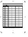
2. STANDARD OPERATION DATA
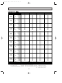
Service Ref.
PE-3EJA 2.TH
Total
Mode
Cooling
Cooling
Cooling
Cooling
Capacity
W
7,200
8,100
9,800
10,900
Input
kW
3.41
3.76
3.59
4.69
PE-3EJA 2.TH
Indoor unit Service Ref.
Electrical Circuit
Phase, Hz
1, 50
1, 60
1, 50
1, 60
V
220
220
220
220
Amperes
A
1.07
1.41
1.41
1.95
PU-3VJA1.TH
PU-3NJA1
PU-4YJSA1.TH
PU-4TJSA2
1, 50
1, 60
3, 50
3, 60
V
220
220
380
220
A
MPa
(kgf/F)
MPa
(kgf/F)
15.1
2.04
(20.8)
0.465
(4.7)
17.6
2.20
(22.4)
0.44
(4.5)
5.7
1.91
(19.5)
0.54
(5.5)
12.2
2.14
(21.8)
0.51
(5.2)
:
64.1
73.2
77.4
77.5
:
52.4
54.2
50.3
54.9
:
4.5
1.3
9.2
6.7
m
5
5
5
5
D.B.
:
27
27
27
27
temperature W.B.
:
19
19
19
19
Discharge air
temperature D.B.
:
13.1
14.2
14.6
15.3
D.B.
:
35
35
35
35
temperature W.B.
:
24
24
24
24
Outdoor unit Service Ref.
Phase, Hz
Amperes
Refrigerant Circuit
PE-4EJSA 2.TH
Volts
Volts
Outdoor side Indoor side
PE-4EJSA 2.TH
Discharge
pressure
Suction
pressure
Discharge
temperature
Condensing
temperature
Suction
temperature
Ref. pipe
length
Intake air
Intake air
The unit of pressure has been changed to Mpa based on SI (International System of Units) in accordance with I.S.O.
(International Organization for Standardization).
Of/F
F)
The conversion factor is : 1(Mpa) =10.2 (O
15
OC155-B--1.qxp
7/26/00 4:43 PM
Page 16
Service Ref.
PE-5EJSA 2.TH
Total
Mode
Cooling
Cooling
Cooling
Cooling
Capacity
W
12,100
13,500
14,000
15,200
Input
kW
5.10
6.06
5.65
6.58
PE-5EJSA2.TH
Indoor unit Service Ref.
Electrical Circuit
Phase, Hz
1, 50
1, 60
1, 50
1, 60
V
220
220
220
220
Amperes
A
2.50
1.99
2.50
1.99
PU-5YJSA.TH
PU-5TJSA1
PU-6YJSA.TH
PU-6TJSA1
3, 50
3, 60
3, 50
3, 60
V
380
220
380
220
A
MPa
(kgf/F)
MPa
(kgf/F)
8.15
1.86
(19.0)
0.48
(4.9)
16.83
1.98
(20.2)
0.43
(4.4)
8.63
1.95
(19.9)
0.44
(4.5)
18.70
2.01
(20.5 )
0.40
(4.1)
:
72.2
78.3
77.8
81
:
49.3
51.9
50.8
52.1
:
- 0.9
1.6
1.7
- 0.5
m
5
5
5
5
D.B.
:
27
27
27
27
temperature W.B.
:
19
19
19
19
Discharge air
temperature D.B.
:
15.5
14.9
14.5
14.1
D.B.
:
35
35
35
35
temperature W.B.
:
24
24
24
24
Outdoor unit Service Ref.
Phase, Hz
Amperes
Refrigerant Circuit
PE-6EJSA2.TH
Volts
Volts
Outdoor side Indoor side
PE-6EJSA 2.TH
Discharge
pressure
Suction
pressure
Discharge
temperature
Condensing
temperature
Suction
temperature
Ref. pipe
length
Intake air
Intake air
The unit of pressure has been changed to Mpa based on SI (International System of Units) in accordance with I.S.O.
(International Organization for Standardization).
Of/F
F)
The conversion factor is : 1(Mpa) =10.2 (O
16
OC155-B--1.qxp
7/26/00 4:43 PM
Page 17
Service Ref.
PE-3EJA 3.TH
Total
Mode
Cooling
Cooling
Capacity
W
7,500
8,100
Input
kW
3.41
3.76
PE-3EJA 3.TH
Indoor unit Service Ref.
Electrical Circuit
Phase, Hz
V
220
220
Amperes
A
1.07
1.41
PU-3VJC.TH
PU-3NJA1
1, 50
1, 60
V
220
220
A
MPa
(kgf/F)
MPa
(kgf/F)
15.1
2.04
(20.8)
0.46
(4.7)
17.6
2.20
(22.4)
0.44
(4.5)
:
88.1
73.2
:
52.4
54.2
:
4.5
1.3
m
5
5
:
27
27
:
19
19
:
15.0
14.2
:
35
35
:
24
24
Outdoor unit Service Ref.
Phase, Hz
Amperes
Refrigerant Circuit
1, 60
Volts
Volts
Outdoor side Indoor side
1, 50
Discharge
pressure
Suction
pressure
Discharge
temperature
Condensing
temperature
Suction
temperature
Ref. pipe
length
D.B.
Intake air
temperature W.B.
Discharge air
temperature D.B.
D.B.
Intake air
temperature
W.B.
The unit of pressure has been changed to Mpa based on SI (International System of Units) in accordance with I.S.O.
(International Organization for Standardization).
Of/F
F)
The conversion factor is : 1(Mpa) =10.2 (O
17
OC155-B--1.qxp
7/26/00 4:43 PM
Page 18
3. FAN PERFORMANCE AND CORRECTED AIRFLOW
Service Ref. : PE-3EJA2.TH
PE-3EJA3.TH
50Hz
60Hz
Recommended range
Recommended range
150
150
100
Hi
Lo
50
0
16
Hi
External static pressure(Pa)
(1Pa = 0.1mmAq)
External static pressure(Pa)
(1Pa = 0.1mmAq)
Airflow (m /min)
(1m /min = 35.3CFM)
18
20
100
Lo
50
0
22
19 20
22
24
60Hz
1.0
0.95
Capacity
Input
0.9
16
18
20
22
Correction factor
Correction factor
50Hz
26
1.0
0.95
0.9
19 20
Airflow (m /min)
22
24
Airflow (m /min)
Service Ref. : PE-4EJSA 2.TH
50Hz
60Hz
Recommended range
Recommended range
150
150
External static pressure(Pa)
(1Pa = 0.1mmAq)
External static pressure(Pa)
(1Pa = 0.1mmAq)
Hi
100
Lo
50
0
20 22 25
30 35 37 40
Hi
100
Lo
50
0
Airflow (m /min)
20 22 25
60Hz
Capacity
0.95
0.9
Input
20 22 25
30 35 37
Airflow (m /min)
Correction factor
Correction factor
50Hz
1.05
1.0
30 35 37 40
Airflow (m /min)
1.05
1.0
0.95
0.9
20 22 25
30 35 37
Airflow (m /min)
18
26
OC155-B--1.qxp
7/26/00 4:43 PM
Page 19
Service Ref. : PE-5EJSA 2.TH
50Hz
60Hz
Recommended range
Recommended range
150
150
Hi
50
0
External static pressure(Pa)
(1Pa = 0.1mmAq)
External static pressure(Pa)
(1Pa = 0.1mmAq)
Hi
100
Lo
27 30
35
40
45 4850
100
Lo
50
0
Airflow (m /min)
27 30
35
1.0
Capacity
0.95
Input
27 30
35
40
45
50
60Hz
45 48
Correction factor
Correction factor
50Hz
1.05
0.9
40
Airflow (m /min)
1.05
1.0
0.95
0.9
Airflow (m /min)
27 30
35
40
45
Airflow (m /min)
Service Ref. : PE-6EJSA 2.TH
50Hz
60Hz
Recommended range
Recommended range
150
150
Hi
50
0
External static pressure(Pa)
(1Pa = 0.1mmAq)
External static pressure(Pa)
(1Pa = 0.1mmAq)
Hi
100
Lo
27 30
35
40
45 48 50
100
Lo
50
0
Airflow (m /min)
27 30
35
1.05
1.0
Capacity
0.95
Input
27 30
35
40
45
60Hz
45 48
Airflow (m /min)
Correction factor
Correction factor
50Hz
0.9
40
Airflow (m /min)
1.05
1.0
0.95
0.9
27 30
35
40
Airflow (m /min)
19
45
50
OC155-B--1.qxp
6
7/27/00 10:22 AM
Page 20
OUTLINES AND DIMENSIONS
Unit : mm (inch)
1. INDOOR UNIT
PE-3EJA2.TH
PE-3EJA3.TH
672(26 1/ 2)
11
600(24)
339(13 3/8)
20(13/16)
40
155
155
155
22.5
24.5
145
(3·9/16)
90
15
145
25
125
35
125
25
175
15
15
(2 3/4)
70
130
250
20
690(27 3/16)
530(20 7/8)
20
200(7 7/8)
200(7/8)
59
50
44
15
70
11
(2 3/8)
75 60 265(10 1/2)
10(3/8)
418(16 1/2)
(4 3/16)
100
(2 3/4)
530(7 7/8)
70
35
20
(13/16)
510(20 1/8)
105
900(36)
345(13 5/8)
(11 13/16)
300
11
25
85
85
25
381(15)
10(3/8)
730(28 3/4)
650(25 5/8)
40
300(11 13/16)
14
220
(8 7/16)
128
235(9 1/4)
(5 1/16)
3.2
40
1
Refrigerant-pipe flared connection [9.52 (3/8)
12
Suspension bolt holes (4-[12 (1/2))
2
Refrigerant-pipe flared connection [15.88 (5/8)
13
14-[3 (1/8) holes
3
Electrical parts box
14
For air outlet duct connection (12-[3 (1/8) holes)
4
Drainage pan
15
Air outlet
5
Drainage pipe connection R1 (male)
16
Mounting plate
6
Service panel (Indoor coil thermistor)
17
Air outlet duct flange
7
Room temperature thermistor
18
Heat insulator t10 (3/8)
8
Heat insulator t10 (3/8)
19
Service space (opening) in the ceiling
9
Air intake duct flange
20
Service panel (Room temperature thermistor)
10
Air intake
21
Duct earth
11
Wiring entry (2-[22 (7/8) holes)
20
OC155-B--1.qxp
7/27/00 10:22 AM
Page 21
Unit : mm (inch)
PE-4EJSA 2.TH
(11 13/16)
300
600(24)
980(38 9/16)
11
345(13 5/8)
339(13·3/8)
4 65(=260)
39.5
65
15
40
175
200(7/8)
22.5
7 65(=455)
35
15
65
15
22.5
(2 3/4)
70
130
250
530(20 7/8)
20
960(27 3/16)
200(7 7/8)
20
11
(3·9/16)
90
15
65
63
55
40
10(3/8)
418(16·1/2)
20(13/16)
11 65(=715)
70
44
35
(3·9/16)
(9 5/8)
245
20
(13/16)
795(31 5/16)
90
(3 3/8) (2 3/4)
85 70
100
(2 3/4)
530(7 7/8)
70
900(36)
11
65
27.5 3 65(=195)
381(15)
40
27.5
10(3/8)
14
250(6 13/16)
(3 7/8)
210(8 1/4)
1000(3 15/16)
920(36 1/4)
500(19 11/16)
98
3.2
40
1
Refrigerant-pipe flared connection [9.52 (3/8)
12
Suspension bolt holes (4-[12 (1/2))
2
Refrigerant-pipe flared connection [19.05 (3/4)
13
34-[3 (1/8) holes
3
Electrical parts box
14
For air outlet duct connection (24-[3 (1/8) holes)
4
Drain pan
15
Air outlet
5
Drain pipe connection R1 (male)
16
Mounting plate
6
Service panel (Indoor coil thermistor)
17
Air outlet duct flange
7
Room temperature thermistor
18
Heat insulator t10 (3/8)
8
Heat insulator t10 (3/8)
19
Service space (opening) in the ceiling
9
Air intake duct flange
20
Service panel (Room temperature thermistor)
10
Air intake
21
Duct earth
11
Wiring entry (2-[22 (7/8) holes)
21
OC155-B--1.qxp
7/27/00 10:22 AM
Page 22
PE-5EJSA 2.TH
PE-6EJSA 2.TH
Unit : mm (inch)
(11 13/16)
300
600(24)
1142(44 15/16)
11
339(13 3/8)
40
65
(3 9/16)
90
15
15
175
200(7 7/8)
13 65(=845)
27.5
15
65
15
27.5
(2 3/4)
70
130
250
530(20 7/8)
20
1160(15 11/16)
200(7 7/8)
20
4 65(=260)
39.5
63
55
65
11
14 65(=910)
70 40
10(3/8)
418(16 1/2)
20(13/16)
(9 5/8)
245
44
35
70
345(13 5/8)
995(39 3/16)
90
20
(13/16)
(3 9/16)
(3 3/8) (2 3/4)
85 70
100
530(7 7/8)
900(36)
11
65
27.5 3 65(=195)
35
10(3/8)
40
14
250(6 13/16)
(3 7/8)
110(4 5/16)
27.5
381(15)
98
3.2
40
1200(47 1/4)
1120(44 1/8)
900(35 7/16)
1
Refrigerant-pipe flared connection [9.52 (3/8)
12
Suspension bolt holes (4-[12 (1/2))
2
Refrigerant-pipe flared connection [19.05 (3/4)
13
40-[3 (1/8) holes
3
Electrical parts box
14
For air outlet duct connection (36-[3 (1/8) holes)
4
Drain pan
15
Air outlet
5
Drain pipe connection R1 (male)
16
Mounting plate
6
Service panel (Indoor coil thermistor)
17
Air outlet duct flange
7
Room temperature thermistor
18
Heat insulator t10 (3/8)
8
Heat insulator t10 (3/8)
19
Service space (opening) in the ceiling
9
Air intake duct flange
20
Service panel (Room temperature thermistor)
10
Air intake
21
Duct earth
11
Wiring entry (2-[22 (7/8) holes)
22
OC155-B--1.qxp
7/27/00 10:22 AM
Page 23
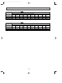
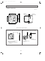
2. REMOTE CONTROLLER
Unit : mm
12
96.5
90.5
3
Upper side wiring
arrangement
opening
3.6
12
8
6
Rear side wiring
arrangememt opening
10
27
9
26
8
25
7
24
6
23
5
22
4
21
3
20
2
19
1
18
TIMER/TEMP.
POWER
COOL
DRY
FAN
UP
HIGH
LOW
ON/OFF
46
28
MODE
SELECT
FAN
SPEED
DOWN
AUTO
STOP
START
TIMER
MODE
4.6
29
11
83.5
TEMP
12
108
117
69
TIMER
3
75
3
3
11.6
9.2
MITSUBISHI ELECTRIC
108
117
Fixing hole
Remote controller cable installation
●For exposed remote controller cable installation
●For recessed remote controller cable installation
Exposed remote controller
cable
Remote controller cable
Conduit tube
(local arrangement)
TIMER
TEMP
12
29
11
28
COOL
10
27
DRY
9
26
8
25
7
24
6
23
5
22
4
21
3
20
2
19
1
18
TIMER/TEMP.
POWER
FAN
UP
HIGH
LOW
ON/OFF
MODE
SELECT
FAN
SPEED
DOWN
AUTO
STOP
START
TIMER
MODE
MITSUBISHI ELECTRIC
Switch box
(local arrangement)
Cable can be connected only to the
top of the remote controller.
(Right side, left side, and buttom are
not possible.)
Set screw (match with switch box),
local arrangement.
Note : The cable for the remote controller has 10m (39ft) length and 12-core with connectors O.D. 5.8.
23
OC155-B--1.qxp
7/26/00 4:43 PM
7
Page 24
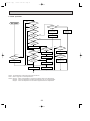
WIRING DIAGRAM
PE-3EJA2.TH / PE-3EJA3.TH / PE-4EJSA2.TH / PE-5EJSA2.TH / PE-6EJSA2.TH
SYMBOL
NAME
SYMBOL
C1
FAN MOTOR CAPACITOR
CN120<I.B>
REMOTE CONTROLLER TRANSMISSION WIRE
CONNECTOR
NAME
SYMBOL
TEMPERATURE / TIMER REMAINING TIME
INDICATOR LED
LD13-24<R.B>
MF1
NAME
R.B
REMOTE CONTROLLER BOARD
T
TRANSFORMER
TB1
POWER SUPPLY TERMINAL BLOCK
TB2
INDOOR / OUTDOOR CONNECTING WIRE TERMINAL BLOCK
RT1
ROOM TEMPERATURE THERMISTOR
(0°C / 15kΩ, 25°C / 5.4kΩ DETECT)
RT2
INDOOR COIL THERMISTOR
( 0°C / 15kΩ, 25°C / 5.4kΩ DETECT)
INDOOR FAN MOTOR
CN51<I.B>
REMOTE INDICATOR CONNECTOR
REMOTE CONTROLLER TRANSMISSION WIRE SW1<I.B>
CONNECTOR
SW2<I.B>
FUNCTION SWITCH
CNR120<R.B>
FI,2<I.B>
FUSE (6.3A 250V)
SW3<I.B>
EMERGENCY OPERATION SWITCH
I.B
INDOOR CONTROLLER BOARD
SW1<R.B>
ON / OFF SWITCH
LD1<R.B>
RUN INDICATOR LED
SW2<R.B>
OPERATION MODE SWITCH
LD3<R.B>
COOLING INDICATOR LED
SW3<R.B>
FAN HIGH / LOW SWITCH
X5<I.B>
FAN MOTOR AUXILIARY RELAY
LD4<R.B>
FAN MODE INDICATOR LED
SW5<R.B>
INDICATOR SWITCH
X6<I.B>
FAN MOTOR AUXILIARY RELAY
LD5<R.B>
FAN HIGH INDICATOR LED
ZNR<I.B>
VARISTOR
LD7<R.B>
INDICATOR MODE TEMPERATURE LED
JR
FUNCTION SELECTOR JUMPER RESISTORS
LD8<R.B>
INDICATOR MODE TIMER LED
LD9<R.B>
DRY INDICATOR LED
LD10<R.B>
FAN LOW INDICATOR LED
LD11<R.B>
OFF TIMER INDICATOR LED
LD12<R.B>
ON TIMER INDICATOR LED
UNIT SWITCH
SW6<R.B>
TEMPERATURE TIMER SETTING UP SWITCH
SW7<R.B>
TEMPERATURE TIMER SETTING DOWN
SWITCH
SW8<R.B>
TIMER CONTINUOUS ON / OFF SWITCH
TB1
RED
BLU
GRN/YLW
MF1
10.6VAC
220V
230V
240V
POWER SUPPLY
~ (1 PHASE)
220-240V
220V
50Hz
60Hz
14.5VAC
RED
ORN
YLW
BLK
BLU
YLW
WHT
RED
ORN
2 3 4 1 5 6
L
N
T
123
123
1234
JR
CN20
INTAKE
CN2A
TWIN-1
1 2
ON
OFF
CN21
PIPE
12
1
TO.RC
CN120
01 02 03 04 05 06
1 2 3
R.B
HEATER
CN31
ON
OFF
SW3
Remote control transmission line
DC 12V with 12 core connector
LD8 LD7
ORN
YLW
TIMER
CN2
SW2
1 2 3 4 5
DRAIN
CN50
SW1
Remote controller
RED
RED
BRN
BRN
1 2 3 4
CN4T
TRANS
ZNR
X6 X5
CN2B
TWIN-2
CNT
TRANS
TB2
L.TEST
CN28
X5
X6
1 3
OUTDOOR
MULTIPLE
CN30
CN51
1 2 3
CND 1 3
POWER
F2
F1
1 2
C1
FAN1 1 3 5 7
WHT
YLW
RED
BLU
BLK
BLU
Indoor unit
I.B
1 2
LD13
LD14
LD15
LD16
LD17
LD18
LD19
LD20
LD21
LD22
LD23
LD24
CNR120
LD1
LD3
LD9
LD4
SW6 LD5
LD10
SW1
SW5
SW2
SW3
SW7
LD11
TO OUTDOOR UNIT
SW8
CONNECTING WIRES
LD12
RT1
RT2
DC 12V(non-polar)
NOTES:
1. Since the indoor transformer (T) is connected with 220V wiring, if 230V or 240V power is used, change the wiring connection as shown fig : 1 w.
When power supply is
fig w1
240V
240 YELLOW
230 ORANGE
230V
220 RED
Since the indoor fan motor (MF1) is connected with 220V 60Hz power, if 200V~240V 50Hz power is used, change the wiring connection as shown fig : 2 w.
fig w2
Indoor fan motor (MF1)
for 200V ~ 240V 50Hz.
BLUE
LD 200—220 230—240 YELLOW
LD
220
BLUE
2. Be sure to refer the outdoor unit electric wiring diagram before wiring of outdoor side unit.
3. Symbols used in wiring diagram above are. / : Terminal block,
: Connector.
4. Emergency operation
If remote controller or microcomputer fails but there is no other trouble, emergency operation is possible by setting dip switch [SW3<I. B>] on the indoor controller board.
[Check items]
(1) Compressor and fan.
(2) Check the trouble position using self diagnostic function. If the result of self diagnosis indicates protective device such as freeze protection is functioning emergency operation is not possible unless the cause is removed.
(3) In emergency operation, the operation made by only ON / OFF circuit breaker manually [ON / OFF with remote controller is not possible].
[Emergency operation procedure]
(1) Cooling is possible by setting 1 . 2 ON and 3 OFF for the dip switch (SW3<I.B>) at indoor controller board.
(2) Turn on outdoor unit side circuit breaker, then indoor unit side circuit breaker in this order.
(3) During emergency operation indoor fan runs at high.
(4) Thermostat will not function.
(5) Do not cooling for more than 10 hours (the indoor unit heat exchanger can freeze).
24
DWG NO. BG79N636H01
OC155-B--1.qxp
7/26/00 4:43 PM
8
Page 25
REFRIGERANT SYSTEM DIAGRAM
Unit : mm
PE-3EJA2.TH / PU-3VJA1.TH, PU-3YJA1.TH, PU-3NJA1
PE-3EJA3.TH, / PU-3NJA1
Refrigerant pipe [15.88(5/8")
(With insulation) option
PE-3EJA 2.TH
Low pressure
switch
Frexible tube
Ball
Valve
Indoor heat
exchanger
High pressure
switch
Check
plug
Charge
plug
Strainer
Flared
connection
Muffier
Indoor coil
thermistor
RT2
PU-3A type
Flared
connection
Outdoor heat
exchanger
Accumulator
Compressor
Capillary tube
For injection
Distributor
with strainer
Capillary tube
(O.D. 3.2 I.D. 1.8
- L800) 2pcs
Ball Valve
(With service port)
Refrigerant pipe [9.52(3/8")
(With insulation) option
Flow of refrigerant
PE-3EJA3.TH / PU-3VJC.TH, PU-3YJC.TH
PE-3EJA3.TH
Indoor heat
exchanger
Refrigerant pipe [15.88(5/8")
(With insulation) option
Low pressure
Flexible tube
strainer
switch
Ball
valve
Indoor heat
exchanger
Charge
pIug
PU-3C type
High pressure
switch
Outdoor heat
exchanger
Check
pIug
Flared
connection
strainer
Flared
connection
Indoor coil
thermistor
RT2
Accumulator
Compressor
Distributor
with strainer
Capillary tube
(O.D. 3.2 oI.D. 1.8 o L800)
o2pcs
Ball valve
(with service port)
Refrigerant pipe [9.52(3/8")
(with heat insulator) option
Flow of refrigerant
25
D.P.R.
(Discharge pressure regulator)
OC155-B--1.qxp
7/26/00 4:43 PM
Page 26
Unit : mm
PE-4EJSA2.TH / PU-4VLJSA1.TH, PU-4YJSA1.TH, PU-4TJSA2
Refrigerant pipe [19.05(3/4")
(With insulator) option
PE-4EJSA2.TH
Low pressure
switch
Flexible tube
Ball
Valve
Charge
plug
High pressure
switch
Check
plug
Strainer
Flared
connection
Indoor heat
exchanger
PU-4 type
Outdoor heat
exchanger
Muffler
Indoor coil
thermistor
RT2
Flared
connection
Accumulator
Compressor
Capillary tube
For injection
(Only PU-4TJSA,
4YJSA)
Distributor
with strainer
Ball Valve
(With service port)
Refrigerant pipe [9.52(3/8")
(With insulator) option
Capillary tube
(O.D.3.2 I.D.1.8
- L1360) 2pcs
Flow of refrigerant
PE-5EJSA2.TH / PU-5YJSA.TH, PU-5TJSA1
PE-6EJSA2.TH / PU-6YJSA.TH, PU-6TJSA1
INDOOR UNIT
PE-5EJSA2.TH
PE-6EJSA2.TH
OUTDOOR UNIT
Refrigerant pipe [19.05 (3/4")
(With insulator) option
Low pressure switch
(only PU-5,6TJSA1)
Flexible tube
PU-5 type
PU-6 type
Check plug
Charge
plug
High
pressure
switch
Ball
valve
Thermal switch
Indoor heat
exchanger
Indoor coil
thermistor
RT2
Flared
connection
Outdoor heat
exchanger
Flared
connection
Distributor
with strainer
Accumulator
Compressor
Capillary tube
PU-5Y·TJSA
(O.D. 4.0 oI.D. 2.4 – L840)o2pcs
PU-6YJSA
(O.D. 4.0 oI.D. 2.4 – L1200)o2pcs
PU-6TJSA
(O.D. 4.0 oI.D. 2.4 – L740)o2pcs
Ball valve
(with service port)
Refrigerant pipe [9.52 (3/8")
(With insulator) option
Strainer
DPR
Capillary tube
PU-5Y·TJSA (O.D. 4.0 oI.D. 2.4 – L400)
PU-6Y·TJSA (O.D. 4.0 oI.D. 2.4 – L200)
Flow of refrigerant
26
OC155-B--1.qxp
9
7/26/00 4:43 PM
Page 27
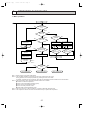
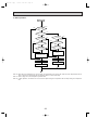
OPERATION FLOW-CHART
1. Main operation
NO
POWER SUPPLY
Live
YES
<Note 1>
TIMER MODE
button ON
YES
NO
During
operation
<Note 2>
NO
Protection device
Self hold reset
ON/OFF
button ON
YES
YES
<Note 3>
YES
Protection device
Self hold
Abnormal
operation mode
NO
NO
NO
AUTO STOP lamp ON
AUTO START lamp ON
Auto stop timer
Press
/ 1 12Hr up
Press
/ 12 1Hr down
Auto start timer
Press / 1 12Hr up
Press / 12 1Hr down
Set time Elapsed time=0
Set time Elapsed time=0
YES
POWER lamp ON
YES
Self-diagnostic function
Indicate & Memory
EMERGENCY
ALL STOP
<Note 4>
<Note 5>
FAN
MODE SELECT
button
DRY
COOL
FAN OPERATION
COOL OPERATION
DRY OPERATION
Note 1. Refer to page 33 for timer mode details.
Note 2. The unit starts operation by pressing the ON / OFF switch when unit is OFF.
During operation, the unit stops operation by pressing the ON / OFF switch.
In addition, operation can be turned ON / OFF with the centralized remote controller or the remote switch.
Note 3. The factors which cause "abnormal operation mode" are as follows.
● Outdoor unit abnormal operation.
● Fault of room temperature thermistor (RT1).
● Fault of indoor coil thermistor (RT2).
● Indoor coil frost protection mode.
● Drain water overflow prevention mode.
Note 4. The indoor fan runs on the low speed for 1 minute to eliminate remaining heat.
Note 5. The compressor will not start for 3 minutes after the stop to protect the compressor.
27
NO
OC155-B--1.qxp
7/26/00 4:43 PM
Page 28
2. COOL operation
YES
3-minute
time delay
YES
6-minute
time delay
NO
NO
NO
NO
YES
Allowanse
Compressor start
3 minutes elapse
Coil frost
protection
check mode
6-minute time delay
<Note 7>
YES
Coil frost
protection
<Note 8>
YES
Allowanse set
NO
Range C
NO
YES
NO
Compressor
start 10 minutes
elapse
YES
Allowance release
NO
Indoor coil
temperature 10 °C
or more
Coil frost
prevention
YES
NO
Continue
1 minute
YES
YES
Fan speed LOW
3-minute time delay
NO
<Note 6>
Compressor
thermostat ON
NO
YES
NO
Compressor
start 16 minutes
elapse
Coil frost
prevention release
YES
NO
Allowance release
Indoor coil
temperature
1°C or below
Fan speed LOW
5 minutes elapse
YES
YES
Outdoor unit abnormality check mode
Coil frost
prevention set
NO
Compressor ON
Compressor OFF
Note 6. The thermostat is continuously ON during the test run.
Note 7. Refer to page 31 for coil frost protection.
Note 8. Range A : Indoor coil temperature is more than 5 degrees above room temperature.
Range B : Indoor coil temperature is within 5 degrees either way of room temperature.
Range C : Indoor coil temperature is more than 5 degrees below room temperature.
28
OC155-B--1.qxp
7/26/00 4:43 PM
Page 29
3. DRY operation
<Note 10>
YES
Room temperature
18 C or below
NO
NO
Compressor ON
YES
YES
3-minute
time delay
NO
Compressor ON
3 min.elapse
NO
YES
NO
<Note 6>
<Note 6>
Compressor
themostat ON
YES
Compressor
thermostat ON
NO
YES
NO
Compressor ON
time completed
Compressor OFF
10 minutes completed
YES
YES
<Note 11>
Compressor ON
time set
Compressor OFF
10-minute timer start
YES
Compressor ON
Compressor OFF
<Note 12>
<Note 12>
Fan speed LOW
Fan stop
Note 10. When the room temperature is 18°C or below, the compressor can not turn ON. When the room temperature rises to
19°C or above, the compressor will start operation after a 3-minute time delay.
Note 11. Refer to page 32 for the compressor operation time.
Note 12. In DRY operation, the indoor fan runs on the low speed during the compressor ON and stops during the compressor
OFF.
29
OC155-B--1.qxp
7/26/00 4:43 PM
10
Page 30
MICROPROCESSOR CONTROL
1. OUTLINE OF MICROPROCESSOR CONTROL
REMOTE CONTROLLER
INPUT to remote controller
OUTPUT to remote controller
● Transmits and receives orders.
● ON-OFF switching.
● COOL-FAN selector switching.
● HIGH-LOW fan speed switching.
● TIMER mode selector switching.
● Thermostat setting.
● Timer setting.
● Self-diagnostic troubleshooting.
● Test run switching.
● Indication lamps lights.
12
TIMER
TEMP
12
29
11
28
COOL
10
27
DRY
9
26
FAN
8
25
7
24
6
23
5
22
4
21
3
20
2
19
1
18
TIMER/TEMP.
UP
POWER
HIGH
LOW
ON/OFF
MODE
SELECT
FAN
SPEED
DOWN
AUTO
STOP
START
TIMER
MODE
MITSUBISHI ELECTRIC
Indoor unit
12V DC
Polar, twelve (12) - core cable
Maximum length 50m (164ft)
INPUT from indoor unit
INDOOR CONTROLLER BOARD
● Room temperature thermistor (RT1)
● Indoor coil thermistor (RT2)
● Receives orders from remote controller and temperature data from
indoor unit.
● Processes orders and data.
● Transmits the power of indication lamp to remote controller.
● Controls indoor and outdoor operation.
● Self-diagnostic function.
W System control operation.<Optional>
W Emergency operation.
OUTPUT to indoor unit
● Fan : ON-OFF.
● Fan speed : HIGH-LOW.
● Emergency stop.
12V DC
Non - polar, two (2) - core cable
INPUT from outdoor unit
● Compressor protection device working
Outdoor unit
OUTDOOR UNIT
● Receives order from indoor
controller.
● Emergency stop.
OUTPUT to outdoor unit
● Compressor motor and outdoor fan motor :
ON - OFF
30
OC155-B--1.qxp
7/26/00 4:43 PM
Page 31
2. INDOOR UNIT CONTROL
2-1 COOL operation
TIMER
TEMP
12
29
11
28
COOL
10
27
DRY
9
26
FAN
8
25
7
24
6
23
5
22
4
21
3
20
2
19
1
18
TIMER/TEMP.
UP
POWER
HIGH
LOW
<How to operate>
1 Press POWER ON / OFF button.
2 Press MODE SELECT button to set operation mode to COOL.
TEMP
3 Check
lamp is ON and set desired temperature with UP or DOWN button.
ON/OFF
MODE
SELECT
NOTES : 1. When
lamp is ON, press DISPLAY SELECT button to change
the display to temperature mode.
FAN
SPEED
DOWN
2. Set temperature changes by 1°C in the range 18 ~ 29°C each time UP
AUTO
STOP
START
or DOWN button is pressed.
3. The lighting lamp shows the set temperature, and the flashing lamp
shows the room temperature.
When the room temperature is equal to the set temperature, the lamp
keeps lighting, 0.5 seconds brightly and 0.5 seconds faintly.
TIMER
MODE
MITSUBISHI ELECTRIC
Steady
TIMER
Flash
OFF
<COOL operation time chart>
Operation starts by
POWER button
ON.
Room temperature
becomes equal to
set temperature.
Room temperature
rises above set
temperature.
Operation stops by
POWER button
OFF.
ON
Thermostat
OFF
LOW or HIGH
LOW or HIGH
ON
Indoor fan
OFF
Compressor
OFF
ON
MIN. 3 minutes
1
W1 Even if the room temperature rise above the set temperature during this period, the compressor will not start until this
period has ended.
(1) Compressor control
1 3 minute time delay
To prevent overload, the compressor will not start within 3 minutes after stop.
2 The compressor runs when the room temperature is higher than the set temperature.
The compressor stops when the room temperature is equal to or lower than the set temperature.
3 The compressor stops in check mode or during protective functions.
4 Coil frost prevention
To prevent indoor coil frost, the compressor will stop when the indoor coil thermistor (RT2) reads 1°C or below after the compressor has been continuously operated for 16 minutes or more. The coil frost prevention is released under any of the following conditions.
● The indoor coil thermistor rises to 10°C or above.
● The room temperature becomes equal to or lower than the set temperature.
● COOL mode is stopped or changed to another mode.
NOTE : By cutting the jumper wire JRO2 on the indoor controller board, the temperature to start coil frost prevention changes
from 1°C to -3°C.
5 Coil frost protection
When indoor coil temperature becomes -15°C or below, coil frost protection will proceed as follows.
<Start condition>
After the compressor has been continuously operated for 3 minutes or more, and the indoor coil temperature has been
-15°C or below for 3 minutes, the coil frost protection will start.
<Coil frost protection>
Compressor stops for 6 minutes, and then restarts.
lf the start condition is satisfied again during the first 10 minutes of compressor operation, both the indoor and outdoor
units stop, and the remote controller displays this occurrence.
<Termination conditions>
Coil frost protection is released when the start condition is not satisfied again during the allowance, or when the COOL
mode stops or changes to another mode.
31
OC155-B--1.qxp
7/26/00 4:43 PM
Page 32
(2) Indoor fan control
Indoor fan speed LOW/HIGH depends on the remote controller setting.
However, if an outdoor unit abnormality is detected, the indoor fan speed will be LOW, regardless of the remote controller
setting.
(3) Detecting abnormalities in the outdoor unit
After the compressor has been continuously operated for 3 minutes, if the difference between the difference between the
indoor coil temperature and room temperature is out of RANGE C, for 1 minute, the indoor fan speed will turn to LOW. Five
minutes later, if the difference is in RANGE C, the fan speed will return to the set speed. If the difference is still out of RANGE
C, the outdoor unit is deemed abnormal.
Thus, the compressor will stop and the trouble location is indicated on the remote controller.
RANGE A : Indoor coil temperature is more than 5 degrees above room temperature.
RANGE B : Indoor coil temperature is within 5 degrees either way of room temperature.
RANGE C : Indoor coil temperature is more than 5 degrees below room temperature.
2-2 DRY operation
<How to operate>
1 Press POWER ON / OFF button.
2 Press MODE SELECT button to set operation mode to DRY.
TIMER
TEMP
12
29
11
28
COOL
10
27
DRY
9
26
FAN
8
25
7
24
6
23
5
22
4
21
3
20
2
19
1
18
TIMER/TEMP.
UP
POWER
HIGH
LOW
3 Check
ON/OFF
AUTO
STOP
NOTES : 1. When
FAN
SPEED
Flash
TIMER
lamp is ON, press DISPLAY SELECT button to change
the display to temperature mode.
2. Set temperature changes by 1°C in the range 18 ~ 29°C each time UP
or DOWN button is pressed.
3. The lighting lamp shows the set temperature, and the flashing lamp
shows the room temperature.
When the room temperature is equal to the set temperature, the lamp
keeps lighting, 0.5 seconds brightly and 0.5 seconds faintly.
TIMER
MODE
MITSUBISHI ELECTRIC
Steady
lamp is ON and set desired temperature with UP or DOWN but-
ton.
MODE
SELECT
DOWN
START
TEMP
OFF
(1) Compressor control
1 3-minute time delay
To prevent overload, the compressor will not start within 3 minutes after stop.
2 The compressor runs when the room temperature is higher than the set temperature.
The compressor stops when the room temperature is equal to or lower than the set temperature.
3 The compressor stops in check mode or during protective functions.
4 The compressor will not start when the room temperature is below 18°C.
The compressor starts intermittent operation when the power is turned ON with room temperature above 18°C. The compressor ON / OFF time depends on the thermostat ON / OFF and the room temperature as follows.
After 3 minute compressor operation,
● If the room temperature thermistor reads above 28°C with thermostat ON, the compressor will operate for 6 more minutes
and then stop for 3 minutes.
● If the room temperature thermistor reads 26 °C ~28 °C with thermostat ON, the compressor will operate for 4 more minutes
and then stop for 3 minutes.
● If the room temperature thermistor reads 24°C ~26°C with thermostat ON, the compressor will operate for 2 more minutes
and then stop for 3 minutes.
● If the room temperature thermistor reads below 24°C with thermostat ON, the compressor will stop for 3 minutes.
● If the thermostat is OFF, regardless of room temperature, the compressor will stop for 10minutes.
5 Coil frost protection
Coil frost protection in DRY operation is the same as in COOL operation.
(2) Indoor fan control
The indoor fan runs on LOW speed during compressor operation. The fan speed cannot be changed with the remote controller.
Also, the indoor fan does not run during compressor OFF.
(3) Detecting abnormalities in the outdoor unit
An abnormality in the outdoor unit can not be detected in DRY operation.
32
OC155-B--2.qxp
7/26/00 4:45 PM
Page 33
2-3 FAN operation
<How to operate>
1 Press POWER ON / OFF button.
2 Press MODE SELECT button to set operation mode to FAN.
TIMER
TEMP
12
29
11
28
10
27
9
26
8
25
7
24
6
23
5
22
4
21
3
20
2
19
1
18
TIMER/TEMP.
POWER
COOL
DRY
FAN
UP
HIGH
LOW
NOTES : Temperature can not be set in FAN operation.
ON/OFF
MODE
SELECT
FAN
SPEED
DOWN
AUTO
STOP
START
TIMER
MODE
MITSUBISHI ELECTRIC
Steady
Flash
OFF
(1) Indoor fan control
The indoor fan speed LOW / HIGH depends on the remote controller setting.
2-4 TIMER operation
TIMER
TEMP
12
29
11
28
COOL
10
27
DRY
9
26
FAN
8
25
7
24
6
23
5
22
4
21
3
20
2
19
1
18
TIMER/TEMP.
UP
POWER
HIGH
LOW
<Timer function>
AUTO STOP ·········Air conditioner stops after the set time lapses.
AUTO START ········Air conditioner starts after the set time lapses.
<How to operate ● AUTO STOP timer>
● POWER
1 While
lamp is lighting, press TIMER MODE button.
ON/OFF
MODE
SELECT
and
FAN
SPEED
DOWN
AUTO
STOP
START
TIMER
MODE
MITSUBISHI ELECTRIC
Steady
Flash
OFF
TIMER
lamps turn ON.
2 Set the time for the AUTO STOP timer with the UP or DOWN button.
NOTE : The time setting is in 1 hour units up to 12 hours.
3 With the lapse of time, the timer lamps turn OFF one by one, showing the remaining time.
4 To cancel the AUTO STOP timer and continue operation, press the TIMER MODE
button.
To cancel the AUTO STOP timer and stop operation, press the POWER ON/OFF
button.
<How to operate AUTO START timer>
POWER
1 While
lamp is OFF, press TIMER MODE button.
and
TIMER
lamps turn ON.
2 Set the time for the AUTO START timer with the UP or DOWN button.
NOTE : The time setting is in 1 hour units up to 12 hours.
3 With the lapse of time, the timer lamps turn OFF one by one, showing the remaining time.
4 To cancel the AUTO START timer and keep the unit OFF, press the TIMER MODE
button.
To cancel the AUTO START timer and start operation, press the POWER ON /
OFF button.
2-5 Test run
The unit starts the test run by pressing both the UP and DOWN buttons simultaneously for more than two seconds during
TIMER
●
●
●
●
lamp ON or the unit OFF.
The test run automatically stops in 2 hours.
Set temperature is not displayed during test run.
Room temperature is displayed by the flashing green lamp when DISPLAY SELECT button is pressed.
The test run can be released by pressing the POWER ON / OFF or the TIMER MODE button.
<Initial setting>
The units are set as follows by the factory.
1) AUTO START set time : 12hours
AUTO STOP set time : 12 hours
2) Initial operation mode : FAN
3) Fan speed
: LOW
4) Set temperature
: 28°C
33
OC155-B--2.qxp
7/26/00 4:45 PM
Page 34
2-6 Self-diagnostic function
! When trouble occurs during operation, the unit stops
and displays the trouble location with the timer lamps
on the remote controller. All the other lamps are OFF
normally.
@ To activate the self-diagnostic function for service,
press the UP and DOWN buttons simultaneously for
more than two
TEMP
seconds during operation with
lamp ON
# The timer lamps show the latest trouble. Trouble data
is memorized until the next trouble occurs, even when
the breaker turns OFF.
$ All buttons except the POWER ON/OFF are unavailable during the self-diagnostic mode.
% To release the self-diagnostic mode, press the
POWER ON /OFF button.
2-7 Emergency operation
When the remote controller or microprocessor malfunctions and no other trouble exists, emergency cooling
operation is available by setting the dip switch on the
indoor controller board.
[Check items]
! Make sure the compressor and the fans are running
normally.
@ Locate the trouble with the self-diagnostic function. If
the self-diagnostic function indicates that the protection device (such as coil frost protection) is functioning,
the sources must be removed before attempting emergency operation.
Emergency operation ON / OFF is activated not with
the remote controller but with the circuit breaker.
[Emergency operation procedure]
! Cooling operation is available by setting the dip switch
(SW3<I.B>) 1 and 2 ON and 3 OFF on the indoor
controller board.
@ To start emergency operation, turn the outdoor side circuit breaker ON first, and then the indoor side circuit
breaker ON.
# During emergency operation, the indoor fan runs on
HIGH speed, the compressor runs continuously.
$ Thermostat will not function.
% Do not use emergency cooling operation for more than
10 hours, as the indoor coil may freeze.
SW3
ON
OFF
1 2 3
34
OC155-B--2.qxp
7/26/00 4:45 PM
Page 35
2-8 Function of jumper wire and dip switch on indoor controller board
1. Jumper wire
1 JR1...Jumper wire for the auto vanes.
Cut JR01 for the unit WITHOUT auto vanes.
2 JR2...Jumper wire for the temperature to start coil frost prevention
Cutting JR02 changes the temperature from +1°C to -3°C.
3 JR3...Jumper wire for set temperature adjustment in HEAT mode.
In HEAT operation, heated air stagnates in the upper part of the room. The indoor unit installed in the upper part of the
room will detect the air temperature higher than the actual temperature in the living space. This difference is about 4
degrees. Therefore, the temperature detected by the room temperature thermistor should be corrected 4 degrees down.
The unit with JR04 attached will make this adjustment.
4 JR4...Jumper wire for the indoor fan speed during thermostat OFF in HEAT mode
Cutting JR04 changes the speed from Extra-Low to Low.
5 JR5...Jumper wire for detecting abnormalities in the outdoor unit
Cutting JR05 makes this detection unavailable. (Occurrence of abnormality can not be detected. )
6 JR6...Jumper wire for auto restart function
Cutting JR06 makes the auto restart function available.
2. Dip switch
1 SW1 (Function switch)
ON
OFF
1 2 3
2 SW2 (Unit switch)
SW1-1) Switch for power supply
ON : 220V
OFF : 230V, 240V
SW1-2) Switch for single or twin control
ON : Twin control
OFF : Single control
SW1-3) Switch for unit number in twin control
(This switch is valid when SW1-2 is ON. )
ON : Unit No. 2
OFF : Unit No. 1
SW2-1)
ON
OFF
1 2 3 4
SW2-2)
SW2-3)
SW2-4)
Switch for air conditioner with or without electric heater
ON : Unit with electric heater
OFF : Unit without electric heater
Switch for air conditioner with or without heat pump
ON : Unit with heat pump
OFF : Unit without heat pump
Switch for function code
ON : 1
OFF : 0
Switch for function code
ON : 1
OFF : 0
3 SW3 (Emergency operation switch)
Normal operation
For emergency cooling
1 2 3
ON
OFF
1 2 3
ON
OFF
35
OC155-B--2.qxp
11
7/26/00 4:45 PM
Page 36
TROUBLESHOOTING
1. SELF-DIAGNOSTIC FUNCTION
! When trouble occurs during operation, the unit stops and enters the self-diagnostic mode, and displays the trouble location with the timer lamps on the remote controller. All the other lamps are OFF.
@ To activate the self-diagnostic function for service, press the UP and DOWN buttons simultaneously for more than two
TEMP.
seconds during operation with
lamp ON.
▲
# The timer lamps show the latest trouble. Trouble data is memorized until the next trouble occurs, even when the breaker
turns OFF. To clear the memory, press the UP and DOWN buttons simultaneously for more than two seconds during the
test run.
$ All buttons except the POWER ON/OFF button are unavailable during the self-diagnostic mode.
% To release the self-diagnostic mode, press the POWER ON/OFF button.
Unit Trouble location
TEMP.
▲
TIMER
Transmission error
in twin control
▲
29
11
28
10
27
9
26
8
25
7
24
6
23
5
22
4
21
3
20
2
19
1
18
Unit
No.2
● Poor connector contact
● Thermistor malfunction
● Check connector
● Check thermistor
➔ No trouble ➔ replace indoor
controller
board.
● Poor connector contact
● Thermistor malfunction
● Check connector
● Check thermistor
➔ No trouble ➔ replace indoor
controller
board.
● Poor connector contact
● Thermistor malfunction
● Check connector
● Check thermistor
➔ No trouble ➔ replace indoor
controller
board.
Drain
overflow
protection
● Drain pump malfunction
● Drain sensor improperly
mounted
● Check drain pump
● Check drain sensor
➔ No trouble ➔ replace indoor
controller
board.
Coil frost
or overheat
prevention
● Air passage short cycle
● Air filter clogged
● Indoor fan malfunction
● Remove blockage
● Check air filter
● Check indoor fan
Indoor coil
thermistor
(RT2)
Unit
No.1 Drain sensor
(DS)
Unit
No.2
Unit
No.1
Unit
No.2
Unit
No.1
Unit
No.2
● Check dip switch setting
● Check wiring
● Check wiring
● Check outdoor unit
● Check outdoor coil thermistor
Unit
Room
No.1 temperature
thermistor
Unit
(RT1)
No.2
Unit
No.1
Measures
● Wrong wiring between
indoor/outdoor units
● Outdoor unit abnormality
detection
● Malfunction of outdoor coil
thermistor
● Reversed phase detected
Outdoor unit
12
Cause
● Wrong wiring between No. 1
and No. 2 units
● Poor connector contact
}
}
}
}
(Indicates that the unit is in self-diagnostic mode)
36
OC155-B--2.qxp
7/26/00 4:45 PM
Page 37
2. OTHER TROUBLES AND CAUSES
Power ON/OFF button
does not work.
Indoor/outdoor connecting wire is connected
incorrectly.
Indoor/outdoor connecting wire shorts.
Compressor protector is
damaged.
Dicer is broken.
Transmission wire is
damaged.
Connector is poorly
connected.
Remote controller is
damaged.
Transmission wire is
poorly connected.
37
OC155-B--2.qxp
7/26/00 4:45 PM
Page 38
3. How to check the parts PE-EJ(S)A.TH
Parts name
Check points
Room temperature
thermistor
(RT1)
Indoor coil thermistor
(RT2)
Disconnect the connector, then measure the resistance using a tester.
(Surrounding temperature 10°C~30°C)
Normal
4.3k'~9.6k'
Trans
1
2
3
4
1
2
3
YLW
RED
CNT(1)-(3)
CN4T(1)-(2)
CN4T(3)-(4)
Fan motor
4
5
6
1
BLK
BLU
YLW
RED
ORN
WHT
BLU
3
BLK
2
Motor terminal
or
Relay connector
WHT-BLK
BLK-BLU
BLU-YLW
YLW-RED
Capacito
5
Normal
WHT App. 135'
BRN App. 0.5~1.0'
RED App. 1.0~2.0'
Abnormal
Open or short
Measure the resistance between the terminals using a tester.
(Surrounding temperature 20°C)
Protector
3
(Refer to the thermistor)
Disconnect the connector and measure the resistance using a tester.
CNT
T
CN4T
BRN
WHT
1
Abnormal
Open or short
7
Normal
PE-EJ(S)A
4EJSA2
20.63'
8.05'
3.18'
16.02'
3EJA2, 3EJA3
46.38'
17.25'
18.37'
(BLU-RED)
<Thermistor Characteristic graph>
Thermistor for
lower temperature
Abnormal
5EJSA2, 6EJSA2
15.26'
5.118'
Open or short
2.648'
14.49'
< Thermistor for lower temperature >
50
Room temperature thermistor(RT1)
Indoor coil thermistor(RT2)
40
Rt=15exp { 3480(
0:
10:
20:
25:
30:
40:
1
273+t
Resistance (K")
Thermistor R0=15k' ± 3%
Fixed number of B=3480k' ± 2%
1 )}
273
30
20
15k'
9.6k'
6.3k'
5.2k'
4.3k'
3.0k'
10
0
38
-20
-10
0
10 20 30
Temperature (:)
40
50
OC155-B--2.qxp
7/26/00 4:45 PM
12
Page 39
DISASSEMBLY PROCEDURE
PE-3EJA2.TH
PE-3EJA3.TH
OPERATING PROCEDURE
PHOTOS&ILLUSTRATIONS
1. Removing the drain pan
! Unscrew each set screw on the right and left, and remove
the drain pan pushing it toward the back.
(See Photo 1)
Photo 1
Room temperature
thermistor
Set screw
(for drain pan)
Drain pan
2. Removing the electrical parts
! Remove the electrical parts cover.
(set screw ✕ 2) and the parts as blow
● Indoor controller board
● Transformer
● Run capacitor
● Fuse (6.3A)
● Terminal block
● Room temperature thermistor
Photo 2
(See Photo 2)
Electrical
parts cover
Set
screw
(See Photo 3)
Photo 3
Transformer
Connector
Terminal
block
3. Removing the indoor coil thermistor
! Remove the drain pan.
Indoor
controller board
Photo 4
Indoor coil
thermistor
(See Photo 1)
@ Remove the electrical parts cover.
(See Photo 2 )
# Remove the set wire of the indoor coil thermistor.
(See Photo 4)
Fan motor
39
Run capacitor
OC155-B--2.qxp
7/26/00 4:46 PM
Page 40
OPERATING PROCEDURE
PHOTOS
4. Removing the fan
Note : Perform the following with the indoor unit lowered down
to the floor.
! Remove the drain pan.
(See Photo 1)
@ Disconnect the connector for the fan motor.
(See Photo 3)
# Take out the fan after removing the 7 set screws of the fan
plate.
(See Photo 5 or 6.)
$ Unscrew four set screws of the bell mouth and remove the
bell mouth.
(See Photo 7.)
% Loosen the set screw of the fan to pull out the sirocco fan.
(See Photo 7.)
^ Unscrew the four set screws of the motor fitting, and
remove the fan motor.
(See Photo 8.)
Photo 5
Fan plate
Set screw
Photo 6
Fan motor
Fan casing
Photo 7
Fan plate
Photo 8
Fixture set screw
Fan casing
Set screw
Bell mouth
Sirocco fan
Fan plate
Set screw
Fixture set screw
Fittings
40
Fan motor
OC155-B--2.qxp
7/26/00 4:46 PM
13
Page 41
PARTS LIST
STRUCTURAL PARTS
PE-3EJA 1.TH
PE-3EJA 2.TH
PE-3EJA 3.TH
9
14
3
4
5
7
2
5
6
8
11
10
12
13
1
Q'ty/set
No.
Part No.
Part Name
Specification
PE-3
EJA1.TH, EJA2.TH, EJA3.TH
Price
Wiring RecomDiagram mended
(Drawing No.) symbol Q'ty
Unit Amount
Remarks
1
E07 027 300
2
—
CASING
1
(R300B098F04)
3
—
BELL MOUTH
1
(R302D730G01)
4
E07 018 500
SIROCCO FAN
1
5
E07 018 808
LEG
2
6
—
FAN PLATE
1
7
—
CABINET ASSY
1
(BG00T021B01)
8
—
AIR OUTLET DUCT FLANGE
1
(BA00H896G08)
9
—
AIR INTAKE DUCT FLANGE
1
(BB02R503G10)
10
—
FAN MOTOR LEG
1
(R302G070G01)
11
—
MOTOR BEAM
1
(BA02L499G04)
12
E07 018 505
RUBBER MOUNT
2
2PCS/SET
13
E07 018 700
DRAIN PAN
1
14
E07 027 620
HEAT EXCHANGER
1
INDOOR FAN MOTOR
PA6V205-E8
41
MF1
1
(BA02G745G10)
OC155-B--2.qxp
7/26/00 4:46 PM
Page 42
STRUCTURAL PARTS
PE-4EJSA1.TH
PE-4EJSA2.TH
12
14
6
3
9
8
7
9
10
11
5
4
2
13
1
Q'ty/set
No.
Part No.
Part Name
Specification
PE-4
EJSA1.TH, EJSA2.TH
Remarks
Wiring RecomDiagram mended
(Drawing No.) symbol Q'ty
1
E07 028 300
INDOOR FAN MOTOR
2
E07 018 505
RUBBER MOUNT
2
3
E07 022 500
SIROCCO FAN
1
4
—
FAN MOTOR LEG
1
(BB00L212G04)
5
—
MOTOR BEAM
1
(BB02T248G02)
6
—
BELL MOUTH
1
(R302D730G01)
7
—
CASING
1
(BA00N328G08)
8
—
CABINET ASSY
1
(BG00T022B01)
PA6V305-EA
MF1
1
2PCS/SET
9
E07 018 808
LEG
2
10
—
FAN PLATE
1
11
—
AIR OUTLET DUCT FLANGE
1
(BA00H896G09)
12
—
AIR INTAKE DUCT FLANGE
1
(BB02G810G05)
13
E07 022 700
DRAIN PAN
1
14
E07 028 620
HEAT EXCHANGER
1
42
(BB02G686G05)
Price
Unit Amount
OC155-B--2.qxp
7/26/00 4:46 PM
Page 43
STRUCTURAL PARTS
PE-5EJSA1.TH, 6EJSA1.TH
PE-5EJSA2.TH, 6EJSA2.TH
5
6
12
14
8 1
4
2
3 10
9
11
5
13
15
7
16
17
Q'ty/set
No.
Part No.
Part Name
Specification PE-5
PE-6
EJSA1.TH EJSA1.TH
Price
Wiring RecomDiagram mended
(Drawing No.) symbol Q'ty
Unit Amount
Remarks
EJSA2.TH EJSA2.TH
1
E07 029 300
1
1
2
—
FAN MOTOR LEG
1
1
(BB00L212G04)
3
—
MOTOR BEAM
1
1
(BB02L182G04)
4
E07 018 505
RUBBER MOUNT
2
2
INDOOR FAN MOTOR
PA6V400-ED
MF1
5
—
BELL MOUTH
2
2
6
E07 018 500
SIROCCO FAN
1
1
7
E07 023 500
SIROCCO FAN
1
1
8
—
CASING
1
1
(R300B098F04)
9
—
CASING
1
1
(R300B098F05)
10
—
FAN PLATE
1
1
(BA02N472G05)
11
—
AIR OUTLET DUCT FLANGE
1
1
(BA00H898G10)
12
E07 018 809
LEFT LEG
1
1
13
E07 018 808
RIGHT LEG
1
1
14
—
CABINET ASSY
1
1
15
E07 023 700
DRAIN PAN
1
1
E07 029 620
HEAT EXCHANGER
1
E07 030 620
HEAT EXCHANGER
16
17
—
(R302D730G01)
(BG00T022B04)
1
AIR INTAKE DUCT FLANGE
1
43
1
(BB02L116G12)
OC155-B--2.qxp
7/26/00 4:46 PM
Page 44
ELECTRICAL PARTS
PE-3EJA1.TH, PE-4EJSA1.TH, PE-5EJSA1.TH, PE-6EJSA1.TH
PE-3EJA2.TH, PE-4EJSA2.TH, PE-5EJSA2.TH, PE-6EJSA2.TH
PE-3EJA3.TH
Q'ty/set
Specification
Remarks
Wiring RecomDiagram mended
(Drawing No.) symbol Q'ty
EJ(S)A1.TH, EJ(S)A2.TH, EJA3.TH
No.
Part No.
Part Name
1
E07 027 447
INDOOR CONTROLLER BOARD
2
E07 006 382
FUSE
1
F1,2<I.B>
3
E07 018 351
INDOOR FAN CAPACITOR 8.0+/440VAC
1
C1
4
E07 027 339
TRANSFORMER
1
T
5
E07 006 375
TERMINAL BLOCK
3P (L, N, ;)
1
TB1
6
E07 007 375
TERMINAL BLOCK
2P (1, 2)
1
TB2
7
E07 027 308
ROOM TEMPERATURE THERMISTOR
1
RT1
8
E07 027 307
INDOOR COIL THERMISTOR
1
RT2
R.B
PE-3,4,5,6
1
250V 6.3A
9
E07 027 426
REMOTE CONTROLLER
1
10
E07 027 088
REMOTE CONTROLLER COVER
1
11
E07 027 089
REMOTE CONTROLLER CABLE 10m
1
12
E07 027 087
0.5m
1
CABLE (FOR BOARD)
w1
w1 : [CONTROLLER CASE] is made together with INDOOR CONTROLLER BOARD.
44
I.B
Price
Unit Amount
OC155-B--2.qxp
7/26/00 4:46 PM
14
Page 45
OPTIONAL PARTS
1. REFRIGERANT PIPES
Service Ref. : PE-3EJA2.TH / PE-3EJA3.TH
Part No.
Pipe length
Pipe size O.D.
Connection method
PAC-05FFS-E
5m
PAC-07FFS-E
7m
Liquid : ø9.52
Indoor unit : Flared
Service Ref. : PE-4EJSA 2.TH, PE-5EJSA 2.TH, PE-6EJSA 2.TH
Part No.
Pipe length
Pipe size O.D.
Connection method
PAC-SC51PI-E
5m
PAC-SC52PI-E
7m
Liquid : ø9.52
Indoor unit : Flared
PAC-10FFS-E
10m
Gas : ø15.88
Outdoor unit : Flared
PAC-15FFS-E
15m
PAC-SC53PI-E
10m
Gas : ø19.05
Outdoor unit : Flared
PAC-SC54PI-E
15m
Note 1. How to connect refrigerant pipes.
Factory supplied optional refrigerant piping contains refrigerant at the above atmospheric pressure. As long as connection takes no more than 5 minutes, no air will enter, and there will be no need for air purging.
Remove the blind caps and make the connections within 5 minutes. After the connections for the indoor and outdoor
units are made, open the stop valve on the outdoor unit to allow refrigerant gas to flow.
If piping length exceeds 20m, an additional charge of refrigerant is needed.
Note 2. The following main parts are contained in the optional refrigerant piping kit.
Heat insulating cover, vinyl tapes, nipples, sleeve, flange (for wall hole).
2. REMOTE CONTROLLER EXTENSION CABLE
When installing the remote controller at a distance from the air conditioner, use the designated extension cable with connector.
Part No.
Length
PAC-905EC
12m
PAC-906EC
20m
PAC-918EC
30m
PAC-919EC
50m
3. TIMER
When using a program timer, a program timer adapter (PAC-825AD) is also needed.
Part No.
Model Name
PAC-SK65PT (with set back function)
Program timer
3-1 Program timer specifications
Part name
Part No.
Exterior dimensions
Installation
Type of clock
Clock accuracy
Display - Time
- Week
- Timer
Program cycle
Timer setting unit
No. of set points
Power rating
Set back function
Program timer
PAC-SK65PT
120 x 120 x 15mm
Wall mount
Quartz
±50s / month
Liquid crystal display
Liquid crystal display
Liquid crystal display
24 hours
30 minutes
48 / day
5V DC
Provided
3-2 Feature of program timer
(1) Daily timer function
Daily timer can be set in 30 minute units up to 24 hours.
Each unit can be set for unit ON, unit OFF, or setback operation.
(2) Setback operation. (PAC-SK65PT)
Set back operation is useful for reducing running costs
e.g. : At a hotel with a 24-hour system
8:00~23:00 Cooling operation with set temperature at 26°C
23:00~8:00 Setback operation with 2 degrees of setback
As shown in the chart on the right, the set temperature rises 2
degrees automatically during the setback operation. When the setback operation ends, normal operation will begin.
(3) Weekly timer function
Daily timer function can apply to each day of the week.
45
28˚C
26˚C
8:00
Normal
operation
23:00
Setback
operation
8:00
Normal
operation
OC155-B--2.qxp
7/26/00 4:46 PM
Page 46
3-3 How to connect program timer
! Install the program timer next to the remote controller the same way as the remote controller is installed.
@ Connect the program timer and the remote controller with a 6-wire cable as shown in the figure below
Connect to indoor unit 2-wire cable
Centralized
Remote
controller
Connect to CN1
Use 6-wire cable
NOTE : While the program timer is connected to the remote
controller, the 24-hour ON / OFF timer on the remote
controller will not operate.
Program
timer
Connect to CN1
3-4 Names and functions
Mode selector button : Use this button to select "MONITOR" or
<PAC-SK65PT>
"SET" mode.
"MONITOR" : Indicates the current timer setting. All buttons except
SET/MONITOR will not work. This is the
normal status.
"SET" : "SET" is used to set the time, change of day of the week, and
program the daily and weekly timer.
Mode display
Current time
display
Current day
display
Weekly timer
display
SET MONITOR
BACK
ON
Clock adjustment button : Used to adjust the current time. Press AHEAD
button to advance the time. Each time the button is
pressed the time advances by 1 minute, and pressing continuously advances 1 minute at a 0. 5 second
interval. When the lower digit of the minutes
becomes 0 the indication advances in 10 minute
units. BACK button is used for reversing the time.
Each time the button is pressed the time reverses by
1 minute, and pressing continuously reverses the
time by 1 minute at a 0. 5 second interval. When the
lower digit of the minute becomes 0 the indication
reverses in 10 minutes units.
BACK
ON
AHEAD
OFF
AHEAD
OFF
MITSUBISHI ELECTRIC
Day setting button :
Used to set the day of the week.
Pressing
button changes the day.
light displays in the order of S ➝ M ➝ T ➝ W.
▼
Daily timer display
NOTE : display above is
only an example.
Weekly timer button : Used to set the weekly timer.
Set back button : Used to set the set back amount.
Set back can be set in the range of 1 to 9°C in 1°C unit.
Daily timer button : Used to set the daily timer in 30 minute units.
46
OC155-B--2.qxp
7/26/00 4:46 PM
Page 47
4. CENTRALIZED REMOTE CONTROLLER
Allows individual or combined control of up to 16 units.
Part No.
PAC-805RC
4-1 Dimensions
Unit : mm
113
56.5
12
23.5
POWER
ON/OFF
ENGAGED
11
POWER
ON/OFF
ENGAGED
GROUP
PROGRAM
TIMER
DUAL CENTRAL
CONTROLLER
OPERATION
BACK
AHEAD
ACTIVE
BYPASS
1 2 3 4 5 6 7 8 9 10
DUAL
CENTRAL
GROUP
SELECTION
ACTIVE BYPASS
PROGRAM
TIMER
DUAL CENTRAL
CONTROLLER
OPERATION
BACK
AHEAD
ACTIVE
BYPASS
113
ACTIVE BYPASS
GROUP
8
GROUP
SELECTION
117
1 2 3 4 5 6 7 8 9 10
DUAL
CENTRAL
MITSUBISHI ELECTRIC
10 9 8 7 6 5 4 3 2 1
117
4-2 Names and Functions
POWER ON/OFF switch
Operation ON/OFF switch.
"ENGAGED" indicator
When this indicator is lit, transmission is in
progress and all switches are inoperative.
DUAL/CENTRAL switch
This change-over switch controls the operation of the accessory remote controller.
▲BACK ▼AHEAD buttons
These buttons are used to designate
the attached unit(s). (They designate
the unit to be centrally controlled.)
POWER
ON/OFF
ENGAGED
GROUP
1 2 3 4 5 6 7 8 9 10
"DUAL"
Instructions from both the accessory
remote controller and the centralized
remote controller are valid. (Priority is
given to the last instruction received.)
GROUP
SELECTION
ACTIVE BYPASS
PROGRAM
TIMER
DUAL CENTRAL
CONTROLLER
OPERATION
"CENTRAL"
ON/OFF switching by the accessory
remote controller is invalidated. Operation
is controlled by the centralized remote controller only.
Initial setting is "DUAL".
BACK
AHEAD
ACTIVE
BYPASS
DUAL
CENTRAL
MITSUBISHI ELECTRIC
LCD Matrix Display
This display indicates the operational status of all connected units either by steady
lighting or by flashing.
●When group “00” is designated; collective ON/OFF instruction is sent to
all units.
●When group ¨01¨ - ¨16¨ is designated;
ON/OFF instruction is sent only to
the designated units.
ACTIVE/BYPASS switch
This change-over switch for the program timer.
(It selects the timer operation on the
program timer.)
Use “BYPASS” when a program timer
is not connected.
“ACTIVE”
The switch turns ON / OFF commands
given from the program timer automatically.
“BYPASS”
ON / OFF Operation is controlled by
the centralized remote controller only.
Initial setting is “BYPASS”.
Independent “DUAL / CENTRAL” and “ACTIVE / BYPASS” setting of all the groups is possible. When power supply to the
centralized remote controller is cut, due to a power failure, for example all settings return to original “DUAL” and “BYPASS”.
47
OC155-B--2.qxp
7/26/00 4:46 PM
Page 48
4-3 Connection method
(1) Connections in the power supply cord.
1. Connect the power supply cord to the power supply terminal-block and fix it in-place with a tie-lap.
Connect a single phase 200V AC (220, 230, 240V) to L N.
As E is the GND terminal, be sure to ground the earth wire.
2. Connect the transmission line to the transmission terminal-block and fix it in-place with a tie-lap.
Use a Ø1.6 (AWG 14) or above two-wire cable for the transmission line.
CAUTION : Never connect the power supply cord to the transmission terminal-block.
TERMINAL-BLOCK
FOR TRANSMISSION
TERMINAL-BLOCK
OF POWER SUPPLY
Transmission
L
T
N
(Y)
240
230
Tle-lap
(O)
220
(R)
200
E
(W) (BN)
5A
TRANSFORMER
Fuse(5A)
L
POWER
SUPPLY
N
Tie-lap
E
Wiring has to be change when
a 200,230 or 240 power is used.
(2) Connection method of centralized remote controller and power supply board.
1. Connect the centralized remote controller and power supply board with a non-polar, two-wire cable.
Power supply board box
To adaptor's
terminal-block
POWER
ON/OFF
ENGAGED
GROUP
1 2 3 4 5 6 7 8 9 10
GROUP
SELECTION
ACTIVE BYPASS
PROGRAM
TIMER
DUAL CENTRAL
CONTROLLER
OPERATION
BACK
AHEAD
ACTIVE
BYPASS
DUAL
CENTRAL
10 9 8 7 6 5 4 3 2 1
Centralized remote
controller
To adaptor's
terminal-block
Non-polar,
two-wire cable
2. Wiring diagram
3. Set the max. address number with the dip switch SW17
of the centralized remote controller.
POWER
ON/OFF
ENGAGED
GROUP
1 2 3 4 5 6 7 8 9 10
Centralized
remote controller
GROUP
SELECTION
ACTIVE BYPASS
PROGRAM
TIMER
DUAL CENTRAL
CONTROLLER
OPERATION
BACK
AHEAD
ACTIVE
BYPASS
DUAL
CENTRAL
Power supply
board
10 9 8 7 6 5 4 3 2 1
48
Dip switch
SW17
OC155-B--2.qxp
7/26/00 4:46 PM
Page 49
5. PROGRAM TIMER ADAPTER
This adapter is needed when a program timer (PAC-SK65PT) or the centralized remote controller (PAC-805RC) is used.
Part No.
PAC-825AD
5-1 Parts included
➀ ADAPTER··························1P
➁ 3-core cable ···························1P
➂ 3-core cable ···························1P
Length : 2m (6' 7")
Length : 2m (6' 7")
➃ 4-core cable ···························1P
➄ 5-core cable ···························1P
Length : 2m (6' 7")
Length : 2m (6' 7")
5-2 Connection method
Connection and wiring methods differ with the type of the indoor unit used. Confirm the type before carrying out the work.
(1) Connections in the adapter Box
1. Connect the power supply cord to the terminal-block and fix it in-place with a tie-lap.
Connect a single phase 200V AC (220, 230, 240V) to L N.
As ; is the GND terminal, be sure to ground the earth wire.
2. Connect the transmission line to the transmission terminal-block and fix it in-place with a tie-lap, when a
centralized remote controller is being used.
CAUTION : Never connect the power supply cord to the transmission terminal-block
fig.1
fig.2
CN22
SW1
SW1
CN22
TRANS
Dip switch
CN1
(AG)
CN21 CN51 CN30 CN42 CN50 CN40
L
Transmission
N
Tie-lap
TERMINAL BLOCK
FOR POWER
SUPPLY
T
(W)
(B)
(Y)
220
-240
TRANS
200
TERMINAL BLOCK
FOR
TRANSMISSION
E
5A
L
N
Tie-lap
Transmission cord
Fuse(5A)
POWER SUPPLY CORD
TRANSFORMER
49
POWER
SUPLLY
OC155-B--2.qxp
7/26/00 4:46 PM
Page 50
(2) Set the address number (from SW1-1 to SW1-6) in
the dip switch when a centralized remote controller is
being used.
The address is the control number of each unit in the
centralized control system.
As the address serves as a time-delay device as
well, sequential starts (all units are triggered collectively by one single ON instruction)must be set with
different address numbers (greater than 0) for each
adapter.
10 9 8 7 6 5 4 3 2 1
ON
SW1
Levers No. 1-6 can set the following addresses respectively
with binary notations.
Toggle No.6 ON No.5 ON No.4 ON No.3 ON No.2 ON No.1 ON
Address
32
16
8
4
2
1
(Ex.1) 3 = 2 + 1
(Ex.2) 9 = 8 + 1
(Ex.3) 15 = 8 + 4 + 2 + 1
10 9 8 7 6 5 4 3 2 1
10 9 8 7 6 5 4 3 2 1
10 9 8 7 6 5 4 3 2 1
ON
ON
(3) Connection from adaptor
ON
40
80
40 27 18
65
12
120
86
Fixing screw hole
4- 5.5
5-core cable 5
ho 15
le
27
35
Remote controller Indoor unit
Max. length of each calbe is 10m.
35
2 2- 2.9
8 7 74
CN2 CN51
15
22
22
3-core cable 2
95
220
CN30 CN50
230
200~240V AC
70
Adaptor
15
5-3 Dimensions
Fig. 4
Fig.3
To program timer
or centralized
remote controller
30
200
6. TIMER ADAPTER
This adapter is needed for system control and for operation via external contacts.
Part No.
PAC-SA89TA-E
ORN
1
BRN
2
RED
3
7. REMOTE INDICATION ADAPTER
This adapter is used for remote indication (operation / check).
PAC-559AD
Part No.
BRN
RED
ORN
YLW
GRN
JST
XHP-3
+
BRN
<Wiring>
-
RED
CN51
+
ORN
-
YLW
-
GRN
5
GREEN
X1
The maximum distance between
indoor boared and relay is 10m.
5
5+
- 2
50
RL
X1
X2
YELLOW
X2
ORANGE
1
connector (5P)
RED
BROWN Electrical insulation is needed
Optional multiple display
Local wiring
adapter
GL
Power
supply
OC155-B--2.qxp
7/26/00 4:46 PM
Page 51
OC155-B--2.qxp
7/26/00 4:46 PM
Page 52
HEAD OFFICE MITSUBISHI DENKI BLDG.MARUNOUCHI TOKYO100-8310 TELEX J24532 CABLE MELCO TOKYO
CCopyright 1997 MITSUBISHI ELECTRIC ENGINEERING CO., LTD.
Issued in Jul. 2000. No. OC155 REVISED EDITION-B 1540
Issued in Dec.1997. No. OC155 REVISED EDITION-A 670
Issued in Sep.1997. No. OC155 860
Printed in Japan.
New publication, effective Jul. 2000.
Specifications subject to change without notice.