1
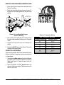
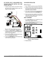
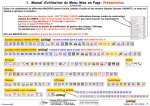
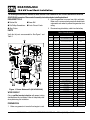
DCA70SSJU4i 19.6 kW Load Bank Installation The following instructions are intended to assist the user in the installation of the 19.6 kW Load Bank for use on the DCA70SSJU4i generators. Please read all assembly instructions before installing load bank. REQUIRED TOOLS 2. Place the generator in an area free of dirt and debris. Make sure it is on secure level ground with chock blocks Ratchet Set Power Drill underneath each wheel to prevent the generator from rolling. Flat/Phillips Screwdrivers 2-Inch Chassis Punch Wire Cutters 3. Disconnect negative battery cable from the battery. PARTS Verify that all parts are accounted for. See Figure 1 and Table 1. 1 2C 10 11 2D 2B 9 2 8 2D 2A 4 3 Table 1. Power Balance Kit Item No. Part No. Description QTY. Remarks 1 MQPPB70J4I KIT, POWER BALANCE, 19kW 1 Includes Items 2-6,8,10,12-18, 29 2 70SSJU4IPBSKIT Kit,Sheet Metal,Power Balance 1 Includes Items 2A-2D 2A EE58360 Angle, Contactor Box Support 1 2B EE58359 Bracket, Contactor Box,14x16" 1 2C EE58361 Cover, Roof,19 kW Resistor 1 2D EE58362 Cover Plate, 2-Row Resistor 2 3 EE58673 2" Rubber Grommet 1 4 EE58325 Resistor Assy. 19 kW 1 5 EE58364 Contactor Assy. 19 kW 1 6 EE58365 Load Bank Wire Harness, 10 AWG. 1 7 Wires Load Bank Split Loom, 3/4" X 126" 126" Obtain Locally Power Wires (UVW-GND), 8 AWG. 1 4 Wires UVW-GND Split Loom, 3/4" X 40" 40" Obtain Locally DC Control Wires, 16 AWG. 1 6 Wires DC Control Split, Loom, 3/8" X 54" 54" Obtain Locally 7 R1 R2 R3 R4 A1 R12 6 R5 A2 R11 R6 A3 A10 R9 HARDWARE 8 27 10 26 A4 A12 A5 R8 A11 A6 R7 A10 A9 A8 A7 7 14 5 ECU 28 Series 800 Controller Engine Started Shutdown 16 Pre-Alarm Screen Alarm Acknowledge Change 12 Option 13 29 INSTRUC TIONS Program/ Exit 19 20 17 21 9 EE58517 11 15 PATENT PENDING EE58515 24 12 EE58370 Tailpipe Extension, 3" Dia. X 13" SS 1 13 EE16745 Clamp,U-Style, 3" Zinc 1 14 EE57143 Decal Power Balance, 5.4” X 1.5” 1 15 EE57145 Decal Patent Pending, 2.70” X 0.55” 1 16 ECU835 ECU Module 1 Fuse, 10 AMP (AGC10) 1 Obtain Locally Fuse Holder, In-Line, 10 AMP 1 Includes Item 17 19 3/8" X 20 Bolt 1 Obtain Locally 17 18 23 25 22 Figure 1. Power Balance Kit (DCA70SSJU4i) WORK SAFELY! Only a qualified service technician with proper training should perform this installation. Follow all shop safety rules when performing this installation. PREPARATION 1. Make sure generator is turned off and engine is cool. 18 303110 20 3/8" Lock Washer 1 Obtain Locally 21 3/8" Flat Washer 1 Obtain Locally 22 G-Clamp 3/8-16" 1 Obtain Locally 23 Tie Wrap, #4 6 Obtain Locally 24 Tie Wrap, #6 10 Obtain Locally 25 Tie Wrap, #8 10 Obtain Locally 26 6mm X 15M Screw 21 Obtain Locally 27 6mm X 15M Lock Washer 21 Obtain Locally 28 6mm X 15M Flat Washer 21 Obtain Locally Work Instructions, Power Balance 1 29 EE58627 DCA70SSJU4i — LOAD BANK INSTRUCTIONS P/N EE58627 — REV. #1 (03/13/15) — PAGE 1 FRONT PANEL REMOVAL (TOW SIDE) TAIL PIPE EXTENSION 1. Locate the generator front panel as shown in Figure 2. 2. Remove the 12 screws (Figure 2 ) that secure the front panel to the cabinet housing. U-CLAMP MOUNTING HARWARE MUFFLER EXHAUST COVER DISCARD WHIS FRONT PANEL PERW ATT CABINET HOUSING Figure 3. Tail Pipe Extension 3. Secure tail pipe extension with U-Clamp (P/N EE16745). GROMMET INSTALLATION MOUNTING HARWARE 1. Using a chassis punch or equivalent tool, cut a 2-inch diameter hole into the front frame cabinet sheet metal as shown in (Figure 4). 13.50” Figure 2. Front Panel/Exhaust Cover Removal 3. Remove front panel, set aside where it will not get damaged. FRONT FRAME EXHAUST COVER REMOVAL 1. Remove the 10 screws that secure the exhaust cover (Figure 2) to cabinet housing. IA. 2.0” D TING EXIS OMMET /GR OLE H ” T L/CU DRIL HOLE W E N 5.50 NT FRO OF ON INET I T EC CAB E KS BAC FRAM 2. Retain mounting hardware. 3. Discard front frame exhaust cover. MUFFLER TAIL PIPE EXTENSION INSTALLATION 1. Locate muffler tail pipe extension (P/N EE58370). 2. Place the flanged end over the existing muffler pipe section as shown in Figure 3. Figure 4. 2-Inch Diameter Hole Cut-Out 2. Remove any sharp edges from the hole opening. 3. Insert 2-inch diameter rubber grommet (P/N EE58673) into hole opening. DCA70SSJU4i — LOAD BANK INSTRUCTIONS P/N EE58627 — REV. #1 (03/13/15) — PAGE 2 ANGLE BRACKET INSTALLATION P/N EE58360 1. Located underneath the voltage selector switch J-box there should be an existing support angle bracket (Figure 5). COVER ROOF ASSY. P/N EE58361 VOLTAGE SELECTOR SWITCH J-BOX CONTACTOR J-BOX ASSY. P/N EE58364 SIDE B EXISTING ANGLE BRACKET SIDE A EXISTING SCREW LOCK WASHER R1 R2 R3 R4 A1 R12 R5 A2 R11 A10 A12 NEW ANGLE BRACKET P/N EE58360 NEW ANGLE BRACKET P/N EE58359 R6 A3 A4 R9 A5 R8 A11 A6 R7 A10 10 AWG 11”.0 RESISTOR LOAD BANK P/N EE58325 A9 A8 A7 6MM SCREWS WITH LOCK/FLAT WASHERS 10 PLACES 10 AWG 11”.7 10 AWG 12”.5 10 AWG 12”.1 Figure 5. Mounting Brackets 10 AWG 12”.2 2. Remove the bottom screws (2) on the existing J-box support angle bracket as shown in Figure 5. 3. Next, attach angle bracket (P/N EE58360) to the existing J-box support angle bracket using the hardware that was removed in step 2. ANGLE BRACKET INSTALLATION P/N EE58359 10 AWG 12” 10 AWG 12”.6 GND. T3 T2 T1 T3 CONTACTOR K1 T2 T1 CONTACTOR K2 CONTACTOR J-BOX P/N EE58359 Figure 6. Load Bank Connections 1. Using 6MM screw (6) with lock washers and flat washers, attach angle bracket (P/N EE58359) onto newly installed angle bracket (P/N EE58360). 2. Insert these seven wires into the 10.5" Load Bank split-loom harness (P/N EE58635). 2. Tighten all screws securely. 3. Once the wires have been inserted into the load bank split-loom harness secure using tie-wraps. CONTACTOR J-BOX INSTALLATION P/N EE58364 4. Next, attach the six wires to the Resistor Load Bank as referenced in Figure 6 and Table 2. Please reference the labeling and length of each wire. 1. U s i n g 6 M M s c r ew ( 4 ) , i n s t a l l C o n t a c t o r J-Box (P/N EE58364) (Figure 5) onto angle bracket P/N EE58359. RESISTOR LOAD BANK WIRING There are seven BLACK 10 AWG wires that need to be connected to Resistor Load Bank P/N (EE58325). Six of the wires are to be connected to the 12 resistors located inside the load bank, the remaining wire will be connected to chassis ground. Connect the 6 resistor load wires and ground wire as follows: 1. Place the Resistor Load Bank with the Side-A facing as shown in Figure 6. Table 2. Resistor Load Bank Wiring Resistor/GND. Load Bank Position Wire Length (ft.) Black 10 AWG R1 A1 12.0 R3 A3 12.6 R5 A5 12.1 R7 A7 12.5 R9 A9 12.2 R11 A11 11.7 GND GND Screw 11.0 5. To prevent arcing, tighten all nuts securely. DCA70SSJU4i — LOAD BANK INSTRUCTIONS P/N EE58627 — REV. #1 (03/13/15) — PAGE 3 R O O F C OV E R / R E S I S TO R L OA D BA N K INSTALLATION Use the procedure below to mount the Resistor Load Bank (P/N EE58325) into the Roof Cover (P/N EE58361). 1. Lift the Resistor Load Bank (Figure 7) upward and align mounting ear holes with flange bracket holes on Roof Cover. COVER ROOF ASSY. P/N EE58361 SIDE B SIDE A 2. Secure Resistor Load Bank to Roof Cover using three 6MM hex head screws. The fourth 6MM screw is for the GND. wire. COVER PLATE (2) ASSY. P/N EE58362 6MM MOUNTING SCREW (12) WITH LOCK/FLAT WASHERS Figure 8. Cover Plate Mounting 5. Place and align the Roof Cover (P/N EE58361) on top of cabinet housing as shown in Figure 9. ROOF COVER P/N EE58361 3 SIDE A 2 GND. WIRE TERMINAL RING R1 R2 R3 R4 A1 R12 R5 A2 R11 A10 A12 4 R6 A3 A4 R9 A5 R8 A11 A6 R7 A10 A9 A8 A7 RESISTOR LOAD BANK P/N EE58325 ROO F P/N COVE R EE5 8361 MOUNTING HARDWARE 1 Figure 7. Roof Cover/Resistor Load Bank Installation 3. Connect the ground wire to the Resistor Load Bank as referenced in (Figure 7). CAB INET HOU SING 4. Using 6MM screw (12) with lock washers and flat washers (Figure 8), install Cover Plate (P/N EE58362) onto A and B sides of Roof Cover (P/N EE58361). Figure 9. Roof Cover Mounting 6. Use the mounting hardware removed in the "Front Frame Exhaust Cover", step 2 to secure the Roof Cover to the cabinet housing. 7. Tighten all screws securely. DCA70SSJU4i — LOAD BANK INSTRUCTIONS P/N EE58627 — REV. #1 (03/13/15) — PAGE 4 RESISTOR LOAD BANK WIRE HARNESS ROUTING 1. There should now be seven wires connected to the Resistor Load Bank. 2. Route the load bank split-loom harness (Figure 10) through the 2-inch rubber grommet on the front frame cabinet. CONTACTOR J-BOX OVERFLOW TANK CONNECT TO RESISTOR LOAD BANK K1 K2 ES 6 WIRTORS TAC CON CONNECTOR BUSHING A11 A5 A1 A7 A9 A3 T3 T2 T1 T3 T2 T1 K2 K1 RUBBER GROMMET GND POIN . T FRONT FRAME CABINET SPLIT-LOOM HARNESS INSTALL 3/8” G-CLAMP Figure 10. Load Bank Split-Loom Harness Routing 3. Next, continue routing the split-loom harness through the front cable connector bushing on the Contactor J-Box. 4. Position the 6 load bank wires near contactors K1 and K2. 5. Position the BLACK ground wire (Figure 10) near the Contactor J-Box ground point. CONTACTOR J-BOX WIRING There are two contactors (K1/K2) that require wiring via the Resistor Load Bank. Connect the six wires to the contactors as shown below: Figure 11. Contactor Wiring Table 3. Contactor J-Box Wiring Load Bank Position Contactor (K1/K2) A1 K1-T1 A5 K1-T2 A9 K1-T3 A7 K2-T1 A11 K2-T2 A3 K2-T3 GND GND Screw 1. Connect the six black wires coming from the Resistor Load Bank to the K1 and K2 contactors as shown in Table 3 and Figure 11. Tighen all wires to 40 in. lbs. (4.52 N.m). 2. Attach the BLACK 10 AWG. ground wire to the Contactor J-Box ground point. Tighten ground wire to 40 in. lbs. (4.52 N.m). DCA70SSJU4i — LOAD BANK INSTRUCTIONS P/N EE58627 — REV. #1 (03/13/15) — PAGE 5 FUSE WIRE HARNESS ROUTING There is a fuse block located inside the Contactor J-Box that contains three 60 amp fuses (F1, F2 and F3). Position load wires to the fuse block as follows: 1. Insert four 8 AWG. RED, BLACK, BLUE and GREEN wires into the 40-inch fuse block split-loom harness (EE58515) as shown in Figure 12. 2. Once the wires have been inserted into the split-loom harness. Secure using tie-wraps. 3. Next, continue routing the split-loom harness through the rear cable connector bushing on the Contactor J-Box. 2. Tighten the nut securing the load wires to the fuse block to 60 in. lbs. (6.78 N.m) 3. Connect the GREEN 10 AWG. ground wire to the Contactor J-Box ground point as shown in Figure 12 and Table 4. Tighten ground wire nut to 40 in. lbs. (4.52 N.m). Table 4. Fuse Wiring Connections (UVW) Wire Length (ft.) Fuse Color (Phase) 8 AWG F1 BLUE (W) 4 F2 BLACK (V) 4 F3 RED (U) 4 4. Position the 3 fuse wires (Figure 12) near the fuse block. If necessary, secure wiring with tie-wraps. OUTPUT TERMINAL PANEL ENCLOSURE REMOVAL 5. Position the GREEN ground wire near the Contactor J-Box ground point. 1. Remove the four screws as shown in Figure 13 that secure the output terminal enclosure to the cabinet frame. OUTPUT TERMINAL PANEL ENCLOSURE REMOVE SCREW 4 PLACES CON TAC J-BO TOR X FUS BLO E CK S IRE K 3 WBLOC E S FU F1 F2 OUTPUT TERMINAL PANEL REAR O W V U F3 GRE BLUE BLK EN RED BLU GRN. GND. POINT ROUTE TO OUTPUT TERMINAL PANEL (REAR, UVW-GND) E BLK 8A 4 PL WG ACE S CONNECTOR BUSHING FUSE BLOCK SPLIT-LOOM HARNESS P/N EE58515 3/4, 48-INCH SPLIT-LOOM HARNESS GND. Figure 12. Fuse Connections FUSE WIRE CONNECTIONS (UVW AND GND.) 1. Connect the three 8 AWG. RED, BLACK, BLUE wires to the load side of the fuse block as shown in Figure 12 and Table 4. RED TO FUSE BLOCK F1 F2 F3 Figure 13. Output Terminal Panel Enclosure Removal 2. Lift and remove the enclosure from the output terminal panel. Set the enclosure aside. DCA70SSJU4i — LOAD BANK INSTRUCTIONS P/N EE58627 — REV. #1 (03/13/15) — PAGE 6 OUTPUT TERMINAL PANEL (UVW-GND.) WIRE CONNECTIONS 1. Connect the four 10 AWG wires RED, BLACK BLUE and GREEN to the rear of the ouput terminal panel as shown in Figure 13 and Table 5. Table 5. UVW-GND Output Terminal Wiring Function Color U RED V BLACK W BLUE 1 N/A O GND. GREEN 1 Terminals O and GND. are bonded Color BROWN RED RED RED/WHT GRN/WHT YELLOW Table 6. DC Control Wiring Contactor J-Box Destination Terminal TB1-1 ECU Pin-57 TB1-2 ECU Pin-16 TB1-2 VS Switch Pin-42 TB1-3 10 AMP Fuse TB1-4 Ground (Ctrl. Bx.) TB1-5 ECU Pin-13 CONTACTOR J-BOX 6-WIRES 2. Once all four wires have been securely connected to the rear of the output terminal panel, re-install output terminal panel enclosure. ALL WIRES 16 AWG. 1 1 2 2 3 3 4 4 4 4 4 4 5 5 DC CONTROL SPLIT LOOM HARNESS (CONTACTOR J-BOX SIDE) There are six wires, (P/N EE58517) that need to be connected to the Contactor J-Box. Connect the wires as shown below. 1. Insert the 6 wires into the 3/8", 54-inch DC Control split-loom harness (P/N EE58517). 2. Once the wires have been inserted into the split-loom harness secure using tie-wraps. 3. One side of this harness (Figure 14) has 6 wires with the insulation stripped back 1/2-inch. The other side has 3 terminal rings attached to the wires. TO ECU,CTRL. BX. VOLTAGE SEL. SW. DC CONTROL 3/8” SPLIT-LOOM HARNESS P/N EE58517 TB1 1 2 3 4 4 4 5 BRN 1 RED DC CONTROL 3/8” SPLIT-LOOM HARNESS P/N EE58517 2 3 4 4 4 5 YEL RED/ GRN/ WHT WHT TO ECU,CTRL. BX. VOLTAGE SEL. SW. Figure 15. DC Control Wiring (TB1) TO CONTACTOR J-BOX (TB1) 5 FT Figure 14. DC Control Split Loom Harness 4. Route the split-loom harness through the front right cable connector bushing on the Contactor J-Box. Be sure to route only the stripped wires up to the J-Box not the terminal ring side. 5. Connect the six wires to the Contactor J-Box as shown in Figure 15 and Table 6. DCA70SSJU4i — LOAD BANK INSTRUCTIONS P/N EE58627 — REV. #1 (03/13/15) — PAGE 7 ECU 830 MODULE REMOVAL NEW ECU 835 MODULE INSTALLATION 1. Loosen the two panel release knobs (Figure 16) that secure the Control Panel to the cabinet frame. 1. Place the new ECU 835 module onto the Control Panel Secure module using the hardware as referenced in step 4 "ECU 830 Module Removal". PANEL RELEASE KNOB 25 50 75 140 180 100 18 12 220 PSI 0 24 °F VOLTS 100 260 6 30 DECREASE INCREASE OIL PRESS WATER TEMP BATTERY ½ 120 150 180 60 RPMX10 E F FUEL 0 V 210 SPEED U W OFF ECU V-W Series 800 Controller Engine Started W-U U-V Shutdown OFF Pre-Alarm Screen Alarm Acknowledge Change Option 2. Re-connect wiring that was removed in step 3 "ECU 830 Module Removal". Reference Table 7. Program/ Exit Figure 16. Control Panel 2. Once the release knobs have been loosened, gently lower the control panel. The backside of the ECU 830 control module is now accessible. 3. Remove all wiring connected to the existing ECU 830 control module. 4. Next, remove the four screws (Figure 17) that secure the existing ECU 830 control module to the Control Panel. Table 7. ECU 835 Wire Connections Pin Number Wire Color Quantity 3 Green 1 4 Red/Orange 1 5 White 1 6 Brown 1 8 White 1 8 White 1 9 Black 1 9 Black 1 12 Pink 1 13 Yellow 1 14 Black/Red 1 16 Red 1 37 White 1 38 Black 1 57 Brown 1 58 Red 1 ECU 830 RETAINING NUT (4) Figure 17. ECU 830 Module Removal 5. Discard the existing ECU 830 Module. DCA70SSJU4i — LOAD BANK INSTRUCTIONS P/N EE58627 — REV. #1 (03/13/15) — PAGE 8 DC CONTROL SPLIT LOOM HARNESS (ECU, VOLTAGE SELECTOR SWITCH, ECU AND CONTROL BOX SIDE 1. Continue routing the free end of the DC Control split-loom harness through the bottom access hole (Figure 18) on the Control Box. GND. 1 BLK 2 3 YELLOW 2. Connect one end of the fuse holder wire (Figure 18) to the 4-pin terminal block located at the rear of the Control Box to terminal 4 (bottom). DECAL PLACEMENT DC CONTROL SPLIT-LOOM HARNESS P/N EE58517 FROM TB1 CONTACTOR J-BOX 1. Place Power Balance decal (P/N EE57143) onto Control Panel as shown in Figure 19. RED BROWN VOLTAGE SELECTOR SWITCH 1. Insert a 10 AMP fuse into the fuse holder (P/N 303110). 4. Once the wiring has been completed, raise the Control Panel back onto the cabinet frame and secure by turning the release knobs clockwise. 4 SPLICE -LINE ADD IN AMP 0 RED/WHT FUSE 1 X O B OL CONTR S ACCES HOLE TERMINAL 42 Reference Figure 18. 3. Next, using a butt splice connector, connect the other end of the fuse holder wire to the RED/WHITE wire. GRN/WHT 4-PIN TERMINAL BLOCK IN-LINE FUSE INSTALLATION RED PIN-57 JUMPER WIRE 2. Next, place Patent Pending decal (P/N EE57145) onto Control Panel as shown in Figure 19. PIN-58 PIN-4 PIN-13 ECU 835 PIN-16 25 50 75 140 180 100 18 12 220 PSI 0 24 °F VOLTS 100 260 6 30 DECREASE INCREASE OIL PRESS WATER TEMP BATTERY ½ Figure 18. DC Control Split-Loom Harness 120 150 180 60 RPMX10 E F FUEL 0 V 210 SPEED U 2. Connect the YELLOW, RED and BROWN wires to the ECU module (pins 13, 16 and 57 respectively) as shown in Figure 18 and Table 6. 3. Next, connect the RED wire with the terminal ring to pin 42 on the Voltage Selector Switch. W OFF ECU V-W Series 800 Controller Engine Started Shutdown W-U U-V OFF Pre-Alarm Screen Alarm Acknowledge Change Option Program/ Exit 4. Connect the GREEN/WHITE wire with the terminal ring to the Control Box ground point. PLACE HERE PLACE HERE PATENT PENDING Figure 19. Decal Placement 3. Reconnect battery. DCA70SSJU4i — LOAD BANK INSTRUCTIONS P/N EE58627 — REV. #1 (03/13/15) — PAGE 9 TESTING Once the Load Bank is installed and ready to test, the ECU 835 Controller must first be updated with the latest firmware to support Load Bank operation. NOTICE The firmware file must be in the main directory (no subfolders). Insert the flash drive into the USB port on the back of the ECU835 controller. 1. Obtain ECU 835 firmware file 0-0-12-0 JD 0-2-0-13.pfw and load to a USB flash drive. 2. Place ECU 835 into “Test Mode”. Test mode is achieved by pressing and holding the hour check button (Figure 20). HOUR CHECK BUTTON 8. Verify and change settings to match the settings shown in Table 8. Use the “Set To” column values. 9. There are two set points that will need to be temporarily set at low values for testing purposes. Once testing is completed, set the Low Load Delay and High Load Trip Reset settings back to the “Set To” column as referenced in Table 8. 10. For testing, use the parameters listed below: Low Load Delay, set to 2 minutes. High Load Trip Reset, set to 1 minute. 11. The following test equipment will be required to complete the testing: A stopwatch to confirm load bank is operating at the correct intervals. External load bank capable of full load in each voltage position. An ammeter to verify current in each voltage mode. 12. Connect the battery terminals and prime the fuel system. Check that oil, coolant and DEF fluid levels are satisfactory. Figure 20. Hour Check Button 3. Next, place the Auto-Off/Reset Manual Switch (Figure 21) in the manual position. AUTO 13. Verify the main circuit breaker is placed in the ON position. 14. Place the voltage selector switch (Figure 22) in the 3ø-240/139 position. MANUAL OFF/RESET Figure 21. Auto-Off/Reset Manual Switch (Manual Position) 4. Release the hour check button. Once in test mode, log onto the ECU835 with the MQ Password. 5. Next, go to advanced options and select upgrade firmware. 6. Select browse for file, and then select the file from the USB. Once selected proceed with the onscreen instructions to complete the firmware update. Figure 22. Voltage Selector Switch 3Ø-240/139 Position 7. Once the update is completed, log back on to the ECU835 with the MQ password. Go to customer options then go to load bank settings. DCA70SSJU4i — LOAD BANK INSTRUCTIONS P/N EE58627 — REV. #1 (03/13/15) — PAGE 10 15. Connect an external load bank to the output terminal panel as shown in Figure 23 and set up for selected voltage mode. Low Load Delay 1. Start the genset and run at no load. 2. Using the voltage regulator adjustment knob, adjust voltage for 3ø-240V E 3-PHAS VOLTMETER 100 0 INCREASE MAIN CIRCUIT BREAKER 500 600 DECREASE VOLTAGE REGULATOR ADJUSTMENT KNOB Figure 23. External Load Bank 16. Place ammeter clamp around Line 1 (L1) on the main circuit breaker. 240 300 400 Figure 25. Voltmeter/VR 3. Start stopwatch. 4. The genset should run without the load bank engaging for the time set for “Low Load Delay”. The test value should be 2 min, so after 2 min (may only take one min) the load bank should automatically turn ON. 5. A powered on Load Bank is indicated by a small “L” on the front screen of the ECU835 (Load Bank On). You should also hear an audible change in the engine load. L3 L1 L2 AMMETER CLAMP 6. On line 1 of the main circuit breaker (Figure 24), the current measured at the ammeter should be approximately 48A with the voltage selector switch set at 3Ø-240V position without additional load from the external load bank. The internal load bank should stay on indefinitely. High Load Level Figure 24. Attaching Ammeter Clamp The next step will test to verify that the internal load bank turns off if a high load level is reached. 1. With the genset still running and the internal load bank on, begin applying load from the external load bank and add load steps equal to a value of approximately 40% of rated load (22-23 kW) for a 70 kVA genset. 2. The internal load bank should remain on. Run for a couple of minutes and then in one additional step, apply an additional 25 kW step from the external load bank. DCA70SSJU4i — LOAD BANK INSTRUCTIONS P/N EE58627 — REV. #1 (03/13/15) — PAGE 11 3. This should be enough load to exceed the “High Load Trip” set point and drop out the internal load bank. This can be verified by a small “T” on the front display of the ECU835 (Torque Exceeded). 4. The “T” should remain for the duration of the “High Load Reset” (60 seconds for test). Once the ECU timer has elapsed, the “T” will go away. 5. The ECU control module is now verifying if the load is above the acceptable load setting (50%) which it should be while at 80% external load. The internal load bank should not attempt to reengage. 6. Remove the external load bank and begin a new stopwatch sequence. 7. After the (Low Load Delay) timer elapses (approximately 2 minutes for test), the internal load bank should come back on. This completes the test for this voltage position. Using the same procedure repeat for 3ø- 480V and 1ø 240V. 480V Position Load Bank Testing For 3 ø- 480V, the load bank line current should be about half of what was measured in the 3ø-240V mode, approximately 24A. Add 25kW step then an additional 25 kW step to trip on High Load Trip. 240V Position Load Bank Testing 1. For 1ø-240V, the load bank line current should be about 54A. This will only be on L1 and L3 when in single phase mode. 2. Add 109 amps to trip on High Load Trip, usually a 50 kW step on a 3ø load bank. 3. As mentioned earlier once testing is completed, set the Low Load Delay and High Load Trip Reset settings back to the values as shown in the “Set To” column. Reference Table 8. Low Load Delay set back to 10 min. High Load Trip Reset set back to 600 Seconds. DCA70SSJU4i — LOAD BANK INSTRUCTIONS P/N EE58627 — REV. #1 (03/13/15) — PAGE 12 Table 8. ECU 835/840 MQ Customer Settings (Load Bank) DCA70 JDT4 Interim Firmware Version 0-0-12-0 JD 0-2-0-13.pfw Set To: Menu Set Point Name Default Unit of Measure Value Load Bank Enable 1 1 1=ON 0=OFF Low Load Trip 46 50 % Torque Sufficient Load Trip 45 50 % Torque High Load Trip 80 92 % Torque Alt Low Load Trip 45 45 % Torque Alt Sufficient Load Trip 45 45 % Torque Alt High Load Trip 80 65 % Torque Low DOC in Temp C 300 300 °C Low Load Delay Min 10 10 Min Load Bank Settings Regen Low Load Delay 10 0 Sec Load Bank Dwell Min 0 60 Min High Load Second Trip 0.1 0.1 Sec High Load Second Reset 60 600 Sec Idle in Load Enable 0 0 1=ON 0=OFF Idle in Load PA 3 3 Sec Idle in Load SD 60 60 Sec Excessive Idle Enable 0 0 1=ON 0=OFF Excessive Idle PA 10 10 Min Excessive Idle SD 15 15 Min DPF TCON High Temp C 1700 1700 °C DPF TCON High Temp Dwell M 1 1 Min DPF TCON Low Temp C -200 -200 °C DPF TCON Low Temp Dewll M 1 1 Min H Enable 0 0 1=ON 0=OFF H Count 1 1 Load Bank 2 TDR Cycle Enable 0 0 1=ON 0=OFF TDR Insuff Load Min 120 120 Min TDR Loadbank On Min 90 90 Min Fault Detect. Enable Second 30 5 5 Sec Enable Load Always On 0 1 1=ON 0=OFF Idle > Rated Reenable Sec 5 5 Sec DCA70SSJU4i — LOAD BANK INSTRUCTIONS P/N EE58627 — REV. #1 (03/13/15) — PAGE 13 DCA70SSJU4i 19.6 kW Load Bank Installation HERE’S HOW TO GET HELP PLEASE HAVE THE MODEL AND SERIAL NUMBER ON-HAND WHEN CALLING UNITED STATES Multiquip Corporate Office 18910 Wilmington Ave. Carson, CA 90746 Contact: [email protected] MQ Parts Department Tel. (800) 421-1244 Fax (310) 537-3927 Service Department 800-421-1244 310-537-3700 800-427-1244 310-537-3700 Fax: 800-672-7877 Fax: 310-637-3284 Warranty Department Fax: 310-537-4259 800-421-1244 310-537-3700 Fax: 310-943-2249 Technical Assistance 800-478-1244 Fax: 310-943-2238 CANADA UNITED KINGDOM Multiquip Multiquip (UK) Limited Head Office 4110 Industriel Boul. Laval, Quebec, Canada H7L 6V3 Contact: [email protected] Tel: (450) 625-2244 Tel: (877) 963-4411 Fax: (450) 625-8664 Unit 2, Northpoint Industrial Estate, Globe Lane, Dukinfield, Cheshire SK16 4UJ Contact: [email protected] Tel: 0161 339 2223 Fax: 0161 339 3226 © COPYRIGHT 2015, MULTIQUIP INC. Multiquip Inc, the MQ logo are registered trademarks of Multiquip Inc. and may not be used, reproduced, or altered without written permission. All other trademarks are the property of their respective owners and used with permission. This manual MUST accompany the equipment at all times. This manual is considered a permanent part of the equipment and should remain with the unit if resold. The information and specifications included in this publication were in effect at the time of approval for printing. Illustrations, descriptions, references and technical data contained in this manual are for guidance only and may not be considered as binding. Multiquip Inc. reserves the right to discontinue or change specifications, design or the information published in this publication at any time without notice and without incurring any obligations. Your Local Dealer is: