1
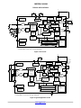
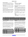
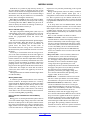
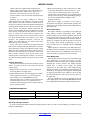
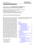
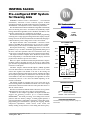
INSPIRIA SA3286
Pre-configured DSP System
for Hearing Aids
INSPIRIA SA3286 features iSceneDetect t environmental
classification, 128−bands of noise reduction, superior feedback
cancellation and built−in feedback path measurement capabilities. The
VOYAGEURt based hybrid sets a new standard of performance.
The iSceneDetect Environment Classification algorithm automatically
senses the hearing aid wearer’s environment and dynamically adjusts
hearing enhancement algorithms (such as Feedback cancellation, noise
reduction, compression, etc.) without user involvement.
Environment classification on Inspiria SA3286 enables programming
of hearing aid to a single program setting which can be employed by the
hearing−aid wearer in all environments instead of manually changing to
a different memory with a change in the acoustic environment.
The Inspiria SA3286 comes with EVOKEt advanced acoustic
indicators. EVOKE allows manufacturers to provide more complex,
multi−frequency tones which can simulate musical notes or chords.
The Inspiria SA3286 iLogt 2.0 Datalogging feature records various
parameters every 4 seconds to 60 minutes (programmable) during use of
the device. Once these parameter values are read from the device, they
can be used to counsel the hearing aid wearer and fine tune the fitting.
The Inspiria SA3286’s Adaptive Noise Reduction monitors noise
levels independently in 128 individual bands and employs advanced
psychoacoustic models to provide user comfort.
Based on a phase cancellation method, Inspiria SA3286’s adaptive
feedback reduction algorithm provides an increase in added stable
gain. It features rapid adjustment for dynamic feedback situations and
resistance to tonal inputs.
Automatic Adaptive Directional Microphone (ADM) algorithm
from ON Semiconductor automatically reduces the level of sound
sources that originate from behind or the side of the hearing−aid
wearer without affecting sounds from the front by adjusting the null in
the microphone polar pattern to minimize the noise level at the output
of the ADM. To reduce current consumption, the algorithm can switch
automatically between 1 mic omni and ADM depending on the
acoustic environment.
The Inspiria SA3286 is equipped with a noise source that can be
used in treating tinnitus. The Tinnitus Treatment noise can be shaped
and attenuated and then summed into the audio path either before or
after the volume control.
The Narrow−band Noise Stimulus feature allows the user to generate
stimuli from the device that can be used for in situ audiometry.
In addition to these adaptive algorithms, the Inspiria SA3286 also
supports the following features: up to 8 channel WDRC,
FRONTWAVE® directional processing, cross fading between audio
paths for click−free memory changes, 16−band graphic equalizer, 8
generic biquad filters (configurable as parametric or other filter types),
programming speed enhancements, optional peak clipping, flexible
compression adjustments, volume control, rocker switch, and
industry−leading security features to avoid cloning and software piracy.
© Semiconductor Components Industries, LLC, 2015
January, 2015 − Rev. 1
1
www.onsemi.com
16 PAD
HYBRID
CASE TBD
PAD CONNECTION
MGND
FMIC
15
RMIC
16
1
VREG
14
2
TIN
VC
13
3
DAI
SDA
12
4
MS
5
MS2
6
VB
7
VBP
GND
11
PGND
10
9
8
OUT+
OUT−
(Bottom View)
MARKING DIAGRAM
SA3286−E1
XXXXXX
SA3286 = Specific Device Code
E1
= RoHS Compliant Hybrid
XXXXXX = Work Order Number
ORDERING INFORMATION
See detailed ordering and shipping information on page 14 of
this data sheet.
Publication Order Number:
SA3286/D
INSPIRIA SA3286
Features
• Advanced Research
• Four Fully Configurable Memories with Audible
128−band Adaptive Noise Reduction
♦ Adaptive Feedback Cancellation
♦ Feedback Path Measurement Tool
♦ Automatic Adaptive Directional Microphones
♦ Environmental Classification
iSceneDetect Environmental Classification 1.0
iLog Datalogging 2.0
Tinnitus Treatment
EVOKE Acoustic Indicators
Auto Telecoil with Programmable Delay
FrontWave Directional Processing
1, 2, 4, 6 or 8 Channel WDRC Compression
AGC−O with Variable Threshold, Time Constants, and
Optional Adaptive Release
16−band Graphic EQ
Narrow−band Noise Stimulus
Optimized Programming Speed
8 Biquadratic Filters
Four Analog Inputs
16 kHz or 8 kHz Bandwidth
Memory Change Indicator
♦
•
•
•
•
•
•
•
•
•
•
•
•
•
•
VREG
MS2
MS
5
4
Voltage
Regulator
1
• 93 dB Input Dynamic Range with HRXt Headroom
•
•
•
•
•
•
•
•
•
Extension
128−bit Fingerprint Security System and Other Security
Features to Protect against Device Cloning and
Software Piracy
High Fidelity Audio CODEC
Soft Acoustic Fade between Memory Changes
Drives Zero−bias 2−terminal Receivers
Internal or External Analog or Digital Volume Control
with Programmable Range
Rocker Switch Support
20−bit Audio Precision
thinSTAX® Packaging
E1 RoHS Compliant Hybrid
thinSTAX Packaging
• Hybrid typical dimensions:
0.215 x 0.124 x 0.067 in.
(5.46 x 3.15 x 1.70 mm)
VB
6
Acoustic
Indicators
Memory
Select
Post
Biquad
Filters
A/D
FMIC 15
RMIC 14
TIN
DAI
2
3
M
U
X
A/D
MIC/TCOIL
COMP
Adaptive
Directional
Microphone
or
FrontWave
*
**
S
Cross
Fader
AGCO
Volume
Control
Environmental
Classification
MGND 16
Frequency
Band
Analysis
SDA 12
Peak
Clipper
128 bands
S
Wideband
Gain
Control
A/D
Data
Logging
WDRC (1,2,4,6 or 8 channels)
Noise Reduction (128 bands)
Clock
Generator
EEPROM
Graphic EQ (16 bands)
11
* If Input Mode = 1 mic omni, mic + telecoil, mic + DAI
** If Input Mode = 2 mic omni, rear only, directional
GND
Figure 1. Hybrid Block Diagram
www.onsemi.com
2
7
VBP
8
OUT−
9
OUT+
10 PGND
Post
Biquad
Filters
Frequency
Band
Synthesis
Programming
Interface
D/A
HBridge
Noise Generator
and Shaper
Feedback
Canceller
Pre
Biquad
Filters
POR
Circuitry
13 VC
INSPIRIA SA3286
Table 1. ABSOLUTE MAXIMUM RATINGS
Parameter
Value
Units
0 to +40
°C
−20 to +70
°C
Absolute Maximum Power Dissipation
25
mW
Maximum Operating Supply Voltage
1.5
VDC
Absolute Maximum Supply Voltage
2
VDC
Operating Temperature Range
Storage Temperature Range
Stresses exceeding those listed in the Maximum Ratings table may damage the device. If any of these limits are exceeded, device functionality
should not be assumed, damage may occur and reliability may be affected.
WARNING: Electrostatic Sensitive Device − Do not open packages or handle except at a static−free workstation.
WARNING:
Moisture Sensitive Device − RoHS Compliant; Level 4 MSL. Do not open packages except under controlled conditions.
Table 2. ELECTRICAL CHARACTERISTICS (VBAT = 1.25 V; Temperature = 25°C) (Note 2)
Parameter
Hybrid Current
Symbol
Conditions
Min
Typ
Max
Units
IAMP
With adaptive features
(NR, FBC, ADM, Datalogging)
8 kHz bandwidth
−
789
−
mA
With adaptive features
(NR, FBC, ADM, Datalogging)
16 kHz bandwidth
−
992
−
No adaptive feature
8 kHz bandwidth
−
590
−
No adaptive feature
16 kHz bandwidth
−
703
−
Minimum Operating Supply Voltage
VBOFF
Ramp down
0.93
0.95
0.97
V
Supply Voltage Turn On Threshold
VBON
Ramp up
1.06
1.1
1.16
V
Minimum Voltage Required for
EEPROM Data Logging
−
−
1.13
−
−
V
EEPROM Burn Cycles
−
−
100 k
−
−
cycles
Low Frequency System Limit
−
−
−
125
−
Hz
High Frequency System Limit
−
32 kHz sampling rate
−
16
−
kHz
Total Maximum System Gain
AV
VIN = −95 dBV at 1 kHz (Note 1)
83
84
85
dB
Converter Gain
AConv
A / D + D / A gain
29
30
31
dB
Total Harmonic Distortion
THD
VIN = −40 dBV
−
−
1
%
THDM
VIN = −15 dBV, HRX − ON
−
−
3
%
fclk
−
1.945
2.048
2.151
MHz
VREG
−
0.87
0.90
0.93
V
Input Referred Noise
IRN
Bandwidth 100 Hz − 8 KHz
−
−108
−106
dBV
Input Impedance
ZIN
−
−
16
−
kW
Anti−aliasing Filter Rejection
−
f = fCLK − 8 kHz, VIN = −40 dBV
−
80
−
dB
Maximum Input Level
−
−
−
−15
−
dBV
Input Dynamic Range
−
HRX − ON Bandwidth
100 Hz − 8 KHz
−
93
−
dB
THD at Maximum Input
Clock Frequency
REGULATOR
Regulator Voltage
INPUT
Product parametric performance is indicated in the Electrical Characteristics for the listed test conditions, unless otherwise noted. Product
performance may not be indicated by the Electrical Characteristics if operated under different conditions.
1. Total system gain consists of: wideband system gain + channel gain + converter gain. Total System gain is calibrated during Cal/Config process.
2. Average currents with auto−ADM or iSceneDetect modes enabled are typically lower.
www.onsemi.com
3
INSPIRIA SA3286
Table 2. ELECTRICAL CHARACTERISTICS (VBAT = 1.25 V; Temperature = 25°C) (Note 2)
Parameter
Symbol
Conditions
Min
Typ
Max
Units
−
−
−
88
−
dB
ZOUT
−
−
−
15
W
RVC
Two−terminal connection
160
200
240
kW
Three−terminal connection
100
−
1000
DA
−
1
−
42
dB
Logic 0 Voltage
−
−
0
−
0.3
V
Logic 1 Voltage
−
−
1
−
1.3
V
Standby Pull Up Current
−
−
1.4
5
6.5
mA
Sync Pull Up Current
−
−
775
900
1100
mA
Logic 0 Current (Pull Down)
−
−
−
450
−
mA
Logic 1 Current (Pull Up)
−
−
−
450
−
mA
TSYNC
Baud = 0
237
250
263
ms
Baud = 1
118
125
132
Baud = 2
59
62.5
66
Baud = 3
29.76
31.25
32.81
Baud = 4
14.88
15.63
16.41
Baud = 5
7.44
7.81
8.20
Baud = 6
3.72
3.91
4.10
Baud = 7
1.86
1.95
2.05
OUTPUT
D/A Dynamic Range
Output Impedance
VOLUME CONTROL
Volume Control Resistance
Volume Control Range
SDA INPUT
SDA OUTPUT
Synchronization Time
(Synchronization Pulse Width)
MS AND MS2 INPUTS
Pull Down / Up Resistance
−
−
−
1
−
MW
Logic 1 Voltage
−
−
VREG
−
VB
V
Rising Edge Threshold
−
−
0.5
0.69
0.9
V
Falling Edge Threshold
−
−
0.25
0.45
0.5
V
Hysteresis
−
−
0.1
0.24
0.4
V
Product parametric performance is indicated in the Electrical Characteristics for the listed test conditions, unless otherwise noted. Product
performance may not be indicated by the Electrical Characteristics if operated under different conditions.
1. Total system gain consists of: wideband system gain + channel gain + converter gain. Total System gain is calibrated during Cal/Config process.
2. Average currents with auto−ADM or iSceneDetect modes enabled are typically lower.
www.onsemi.com
4
INSPIRIA SA3286
TYPICAL APPLICATIONS
VB
5
Voltage
Regulator
1
Acoustic
Indicators
Memory
Select
Σ
Post
Biquad
Filters
15
A/D
3k9
14
3k9
3
MIC/
TCOIL
Comp
A/D
M
U
X
2
1k
6
4
*
16
Programming
Interface
Cross
Fader
**
OUT
D/A
HBridge
Peak
Clipper
Σ
Volume
Control
AGCO
8
9
LP
Filter
10
Wide−
band
Gain
Control
A/D
13
200 k
Post
Biquad
Filters
Environmental
Classification
128 bands
Frequency
Band
Analysis
7
Noise Generator
and Shaper
Feedback
Canceller
Pre
Biquad
Filters
1k
12
Adaptive
Directional
Microphone
or
FrontWave
POR
Circuitry
Frequency
Band
Synthesis
Data
Logging
WDRC (1,2,4,6 or 8 channels)
Noise Reduction (128 bands)
Clock
Generator
EEPROM
Graphic EQ (16 bands)
11
* If Input Mode = 1 mic omni, mic + telecoil, mic + DAI
** If Input Mode = 2 mic omni, rear only, directional
Figure 2. Test Circuit
VB
5
1
Voltage
Regulator
2
3
A/D
MIC/
TCOIL
Comp
Adaptive
Directional
Microphone
or
FrontWave
*
**
Programming
Interface
Frequency
Band
Analysis
S
POR
Circuitry
Peak
Clipper
Cross
Fader
7
D/A
HBridge
Noise Generator
and Shaper
Feedback
Canceller
AGCO
Pre
Biquad
Filters
16
12
Acoustic
Indicators
Post
Biquad
Filters
14
M
U
X
6
Memory
Select
A/D
15
4
S
Volume
Control
Wide−
band
Gain
128 bands
Frequency
Band
Synthesis
Control
A/D
Data
Logging
WDRC (1,2,4,6 or 8 channels)
Noise Reduction (128 bands)
Clock
Generator
Graphic EQ (16 bands)
11
* If Input Mode = 1 mic omni, mic + telecoil, mic + DAI
** If Input Mode = 2 mic omni, rear only, directional
Figure 3. Typical Application Circuit
www.onsemi.com
5
9
10
Post
Biquad
Filters
Environmental
Classification
8
EEPROM
13
Knowles or
Microtronic
zero−bias
receiver
INSPIRIA SA3286
T−coil
+
MS
switch
(N.O.)
−
Front
Mic
+
Zero Biased
Receiver
Rear
Mic
+
VC
CS44
Figure 4. Typical Hearing Instrument Assembly Diagram
INSPIRIA SA3286 Overview
Inspiria SA3286 is a DSP system with adaptive
algorithms that run on the Voyageur hardware platform. This
hardware platform is a combination of a DSP core and a high
fidelity audio CODEC. The thinSTAX packaging provides
easy integration into a wide range of applications from CIC
to BTE.
The DSP core implements FrontWave directional
processing, programmable filters, adaptive algorithms,
compression, wideband gain, and volume control. The
adaptive algorithms include Adaptive Noise Reduction,
Adaptive Feedback Cancellation and Automatic Adaptive
Directional Microphones.
The Adaptive Noise Reduction reduces audible noise in a
low distortion manner while preserving perceived speech
levels. The Adaptive Feedback Canceller reduces acoustic
feedback while offering robust performance against pure
tones. The Adaptive Directional Microphone (ADM)
algorithm automatically reduces the level of sound sources
that originate from behind or from the side of the
hearing−aid wearer without affecting sounds from the front.
Additionally, the Automatic Adaptive Directional
Microphones algorithm automatically reduces current by
turning off the second input channel if it is not needed.
The Inspiria SA3286 iLog 2.0 Datalogging feature
records various parameters every 4 seconds to 60 minutes
(programmable) during use of the device. Once these
parameter values are read from the device, they can be used
to counsel the user and fine tune the fitting.
iSceneDetect 1.0 is the Inspiria SA3286’s classification
algorithm that senses the users environment and
automatically optimizes the hearing aid to maximize user
comfort and audibility in that environment without any user
interaction.
The Inspiria SA3286 comes with Evoke advanced
acoustic indicators. Evoke allows manufacturers to provide
more complex, multi−frequency tones, in addition to
traditional programmable tones for memory changes and
low battery indication, which can simulate musical notes or
chords.
The Inspiria SA3286 is equipped with a noise source that
can be used in treating tinnitus. The Tinnitus Treatment
noise can be shaped and attenuated and then summed into
the audio path either before or after the volume control.
The Narrow−band Noise Stimulus feature allows the user
to generate stimuli from the device that can be used for in situ
audiometry.
The Inspiria SA3286 utilizes the power and capabilities of
Voyageur to deliver advanced features and enhanced
performance previously unavailable to a product in its class.
As well, the Inspiria SA3286 contains security features to
protect clients’ Intellectual Property against device cloning
and software piracy.
Signal Path
There are two main audio input signal paths. The first path
contains the front microphone and the second path contains
the rear microphone, telecoil or direct audio input as selected
by a programmable MUX. The front microphone input is
intended as the main microphone audio input for single
microphone applications.
In iSceneDetect, FrontWave, ADM or Automatic ADM
operation, a multi−microphone signal is used to produce a
directional hearing instrument response. The two audio
inputs are buffered, sampled and converted into digital form
using dual A/D converters. The digital outputs are converted
into a 32 kHz or 16 kHz, 20−bit digital audio signal. Further
IIR filter blocks process the front microphone and rear
microphone signals. One biquad filter is used to match the
rear microphone’s gain to that of the front microphone. After
that, other filtering is used to provide an adjustable group
delay to create the desired polar response pattern during the
calibration process. In iSceneDetect, ADM and Automatic
ADM, the two microphone inputs are combined in an
adaptive way while in FrontWave operation the combination
is static.
www.onsemi.com
6
INSPIRIA SA3286
In the Telecoil mode gains are trimmed during Cal/Config
process to compensate for microphone/telecoil mismatches.
The FrontWave block is followed by four cascaded biquad
filters: pre1, pre2, pre3 and pre4. These filters can be used
for frequency response shaping before the signal goes
through channel and adaptive processing.
The channel and adaptive processing consists of the
following:
• Frequency band analysis
• 1, 2, 4, 6 or 8 channel WDRC
• 16 frequency shaping bands (spaced linearly at 500 Hz
intervals, except for first and last bands)
• 128 frequency band adaptive noise reduction
• Frequency band synthesis
After the processing the signal goes through two more
biquad filters, post1 and post2, which are followed by the
AGC−O block. The AGC−O block incorporates the
Wideband Gain and the Volume Control. There are also two
more biquad filters, post3 and post4, and the Peak Clipper.
The last stage in the signal path is the D/A H−bridge.
White noise can be shaped, attenuated and then added into
the signal path at two possible locations: before the Volume
Control (between the Wideband Gain and the Volume
Control) or after the Volume Control (between post 4 and the
Peak Clipper) as shown in Figure 1.
A unique indicator sound can be assigned to each of the
seven system events: memory select (A, B, C or D), low
battery warning, digital VC movement and digital VC
minimum/maximum. Each sound can consist of a number of
either pure tones or damped tones but not both.
A pure tone sound can consist of up to four tones, each
with a separate frequency, amplitude, duration and start
time. Each frequency component is smoothly faded in and
out with a fade time of 64 ms. The start time indicates the
beginning of the fade in. The duration includes the initial
fade−in period. By manipulating the frequencies, start times,
durations and amplitudes various types of sounds can be
obtained (e.g., various signalling tones in the public
switched telephone network).
A damped tone sound can consist of up to six tones, each
with a separate frequency, amplitude, duration, start time
and decay time. Each frequency component starts with a
sudden onset and then decays according to the specified time
constant. This gives the audible impression of a chime or
ring. By manipulating the frequencies, start times,
durations, decays and amplitudes, various musical melodies
can be obtained.
Acoustic indication can be used without the need to
completely fade out the audio path. For example, the
low−battery indicator can be played out and the user can still
hear an attenuated version of the conversation.
Functional Block Description
Adaptive Feedback Canceller
The Adaptive Feedback Canceller (AFC) reduces
acoustic feedback by forming an estimate of the hearing aid
feedback signal and then subtracting this estimate from the
hearing aid input. The forward path of the hearing aid is not
affected. Unlike adaptive notch filter approaches, the
Inspiria SA3286’s AFC does not reduce the hearing aid’s
gain. The AFC is based on a time−domain model of the
feedback path.
The third-generation AFC (see Figure 5) allows for an
increase in the stable gain1 of the hearing instrument while
minimizing artefacts for music and tonal input signals. As
with previous products, the feedback canceller provides
completely automatic operation.
(Added stable gain will vary based on hearing aid style and
acoustic setup. Please refer to the Adaptive Feedback
Cancellation Information note for more details.)
iSceneDetect 1.0 Environment Classification
The iSceneDetect feature, when enabled, will sense the
environment and automatically control the enhancement
algorithms without any user involvement. It will detect
speech in quiet, speech in noise, wind, music, quiet and noise
environments and make the necessary adjustments to the
parameters in the audio path, such as ADM, ANR, WDRC,
FBC, in order to optimize the hearing aid settings for the
specific environment.
iSceneDetect will gradually make the adjustments so the
change in settings based on the environment is smooth and
virtually unnoticeable. This feature will enable the hearing
aid wearer to have an instrument which will work in any
environment with a single memory.
EVOKE Advanced Acoustic Indicators
Advanced acoustic indicators provide alerting sounds that
are more complex, more pleasing and potentially more
meaningful to the end user than the simple tones used on
previous products. The feature is capable of providing
pulsed, multi−frequency pure tones with smooth on and off
transitions and also damped, multi−frequency tones that can
simulate musical notes or chords.
When the AFC is enabled, it is highly recommended that
you either have all channels with Squelch ON or all channels
with Squelch OFF. If you choose to have all channels with
Squelch ON then there is an additional requirement to have
all Squelch thresholds above the microphone noise floor. If
you require any assistance in determining what threshold
levels to set, please contact the applications department at
ON Semiconductor. Squelch ON/OFF does not incur any
current penalty. When Squelch and AFC are both ON, the
Squelch is limited to 1:2 expansion.
www.onsemi.com
7
INSPIRIA SA3286
Feedback path
+
−
Directional Microphones
H
In any directional mode, the circuitry includes a fixed
filter for compensating the sensitivity and frequency
response differences between microphones. The filter
parameters are adjusted during product calibration.
A dedicated biquad filter following the directional block
has been allocated for low frequency equalization to
compensate for the 6 dB/octave roll−off in frequency
response that occurs in directional mode. The amount of low
frequency equalization that is applied is programmable.
ON Semiconductor recommends using matched
microphones. The maximum spacing between the front and
rear microphones cannot exceed 20 mm (0.787 in).
G
Σ
H’
Estimated feedback
Figure 5. Adaptive Feedback Canceller (AFC)
Block Diagram
Adaptive Directional Microphones
Feedback Path Measurement Tool
ON Semiconductor’s Adaptive Directional Microphone
(ADM) algorithm is a two−microphone processing scheme
for hearing aids. It is designed to automatically reduce the
level of sound sources that originate from behind or the side
of the hearing−aid wearer without affecting sounds from the
front. The algorithm accomplishes this by adjusting the null
in the microphone polar pattern to minimize the noise level
at the output of the ADM. The discrimination between
desired signal and noise is based entirely on the direction of
arrival with respect to the hearing aid: sounds from the front
hemisphere are passed unattenuated whereas sounds
arriving from the rear hemisphere are reduced.
The angular location of the null in the microphone polar
pattern is continuously variable over a range of 90 to 180
degrees where 0 degrees represents the front.
The location of the null in the microphone pattern is
influenced by the nature of the acoustic signals (spectral
content, direction of arrival) as well as the acoustical
characteristics of the room. The ADM algorithm steers a
single, broadband null to a location that minimizes the
output noise power. If a specific noise signal has frequency
components that are dominant, then these will have a larger
influence on the null location than a weaker signal at a
different location. In addition, the position of the null is
affected by acoustic reflections. The presence of an acoustic
reflection may cause a noise source to appear as if it
originates at a location other than the true location. In this
case, the ADM algorithm chooses a compromise null
location that minimizes the level of noise at the ADM
output.
The Feedback Path Measurement Tool uses the onboard
feedback cancellation algorithm and noise generator to
measure the acoustic feedback path of the device. The noise
generator is used to create an acoustic output signal from the
hearing aid, some of which leaks back to the microphone via
the feedback path. The feedback canceller algorithm
automatically calculates the feedback path impulse response
by analyzing the input and output signals. Following a
suitable adaptation period, the feedback canceller
coefficients can be read out of the device and used as an
estimate of the feedback−path impulse response.
Adaptive Noise Reduction
The noise reduction algorithm is built upon a high
resolution 128−band filter bank enabling precise removal of
noise. The algorithm monitors the signal and noise activities
in these bands, and imposes a carefully calculated
attenuation gain independently in each of the 128 bands.
The noise reduction gain applied to a given band is
determined by a combination of three factors:
• Signal−to−Noise Ratio (SNR)
• Masking threshold
• Dynamics of the SNR per band
The SNR in each band determines the maximum amount
of attenuation to be applied to the band − the poorer the SNR,
the greater the amount of attenuation. Simultaneously, in
each band, the masking threshold variations resulting from
the energy in other adjacent bands is taken into account.
Finally, the noise reduction gain is also adjusted to take
advantage of the natural masking of ‘noisy’ bands by speech
bands over time.
Based on this approach, only enough attenuation is
applied to bring the energy in each ‘noisy’ band to just below
the masking threshold. This prevents excessive amounts of
attenuation from being applied and thereby reduces
unwanted artifacts and audio distortion. The Noise
Reduction algorithm efficiently removes a wide variety of
types of noise, while retaining natural speech quality and
level. The level of noise reduction (aggressiveness) is
configurable to 3, 6, 9 and 12 dB of reduction.
Automatic Adaptive Directional Microphones
When Automatic ADM mode is selected, the adaptive
directional microphone remains enabled as long as the
ambient sound level is above a specific threshold and the
directional microphone has not converged to an
omni−directional polar pattern. On the other hand, if the
ambient sound level is below a specific threshold, or if the
directional microphone has converged to an
omni−directional polar pattern, then the algorithm will
switch to single microphone, omni−directional state to
www.onsemi.com
8
INSPIRIA SA3286
Tinnitus Treatment
reduce current consumption. While in this omni−directional
state, the algorithm will periodically check for conditions
warranting the enabling of the adaptive directional
microphone.
The Inspiria SA3286 has an internal white noise generator
that can be used for Tinnitus Treatment. The noise can be
attenuated to a level that will either mask or draw attenuation
away from the user’s tinnitus. The noise can also be shaped
using low−pass and/or high−pass filters with adjustable
slopes and corner frequencies.
As shown in Figure 1, the Tinnitus Treatment noise can be
injected into the signal path either before or after the volume
control (VC) or it can be disabled. If the noise is injected
before the VC then the level of the noise will change along
with the rest of the audio through the device when the VC is
adjusted. If the noise is injected after the VC then it is not
affected by VC changes.
The Tinnitus Treatment noise can be used on it’s own
without the main audio path in a very low power mode by
selecting the Tinnitus Treatment noise only. This is
beneficial either when amplification is not needed at all by
a user or if the user would benefit from having the noise
supplied to them during times when they do not need
acoustic cues but their sub−conscious is still active, such as
when they are asleep.
The ARK software has a Tinnitus Treatment tool that can
be used to explore the noise shaping options of this feature.
This tool can also be easily incorporated into another
software application.
FrontWave Directionality
The FrontWave block provides the resources necessary to
implement directional microphone processing. The block
accepts inputs from both a front and rear microphone and
provides a synthesized directional microphone signal as its
output. The directional microphone output is obtained by
delaying the rear microphone signal and subtracting it from
the front microphone signal. Various microphone response
patterns can be obtained by adjusting the time delay.
In−Situ Datalogging − iLog 2.0
The Inspiria SA3286 has a datalogging function that
records information every 4 s to 60 minutes (programmable)
about the state of the hearing aid and its environment to
non−volatile memory. The function can be enabled with the
ARK software and information collection will begin the
next time the hybrid is powered up. This information is
recorded over time and can be downloaded for analysis.
The following parameters are sampled:
• Battery level
• Volume control setting
• Program memory selection
• Environment
• Ambient sound level
• Length of time the hearing aid was powered on
The information is recorded using two methods in
parallel:
• Short−term method − a circular buffer is serially filled
with entries that record the state of the first five of the
above variables at the configured time interval.
• Long−term method − increments a counter based on the
memory state at the same time interval as that of the
short−term method. Based on the value stored in the
counter, length of time the hearing aid was powered on
can be calculated.
There are 750 log entries plus 4 memory select counters
which are all protected using a checksum verification. A
new log entry is made whenever there is a change in memory
state, volume control, or battery level state. A new log entry
can also be optionally made when the environmental sound
level changes more than the programmed threshold, thus it
is possible to log only significantly large changes in the
environmental level, or not log them at all.
The ARK software iLog graph displays the iLog data
graphically in a way that can be interpreted to counsel the
user and fine tune the fitting. This iLog graph can be easily
incorporated into other applications or the underlying data
can be accessed to be used in a custom display of the
information.
Narrow−band Noise Stimulus
The Inspiria SA3286 is capable of producing Narrow−
band Noise Stimuli that can be used for in situ audiometry.
Each narrow−band noise is centred on an audiometric
frequency. The duration of the stimuli is adjustable and the
level of the stimuli are individually adjustable.
A/D and D/A Converters
The system’s two A/D converters are second order
sigma−delta modulators operating at a 2.048 MHz sample
rate. The system’s two audio inputs are pre−conditioned
with antialias filtering and programmable gain
pre−amplifiers. These analog outputs are over−sampled and
modulated to produce two, 1−bit Pulse Density Modulated
(PDM) data streams. The digital PDM data is then
decimated down to Pulse−Code Modulated (PCM) digital
words at the system sampling rate of 32 kHz.
The D/A is comprised of a digital, third order sigma−delta
modulator and an H−bridge. The modulator accepts PCM
audio data from the DSP path and converts it into a 64−times
or 128−times over−sampled, 1−bit PDM data stream, which
is then supplied to the H−bridge. The H−bridge is a
specialized CMOS output driver used to convert the 1−bit
data stream into a low−impedance, differential output
voltage waveform suitable for driving zero−biased hearing
aid receivers.
www.onsemi.com
9
INSPIRIA SA3286
HRX Head Room Expander
The number of compression channels is programmable in
ARKonline® and can be 1, 2, 4, 6 or 8.
The Inspiria SA3286 has an enhanced Head Room
Expander (HRX) circuit that increases the input dynamic
range of the Inspiria SA3286 without any audible artifacts.
This is accomplished by dynamically adjusting the
pre−amplifier’s gain and the post−A/D attenuation
depending on the input level.
Telecoil Path
The telecoil input is calibrated during the Cal/Config
process. To compensate for the telecoil/microphone
frequency response mismatch, a first order filter with
500 Hz corner frequency is implemented. Through
ARKonline, it is possible to implement a telecoil
compensation filter with an adjustable corner frequency. To
accommodate for the gain mismatch, the telecoil gain is
adjusted to match the microphone gain at 500 Hz or 1 kHz
(default) and is selectable in ARKonline.
There is also a telecoil gain adjustment parameter that can
be enabled in ARKonline and set in IDS, enabling manual
adjustment of the telecoil gain compensation.
Channel Processing
Figure 6 represents the I/O characteristic of independent
AGC channel processing. The I/O curve can be divided into
the following main regions:
• Low input level expansion (squelch) region
• Low input level linear region
• Compression region
• High input level linear region (return to linear)
Automatic Telecoil
0
OUTPUT LEVEL (dBV)
−20
−30 Low Level
−40 Gain
−50
−60
−70
−80
The Inspiria SA3286 is equipped with an automatic
telecoil feature, which causes the hybrid to switch to a
specific memory upon the closing of a switch connected to
MS2. This feature is useful when MS2 is connected to a
switch, such as a reed switch, that is open or closed
depending on the presence of a static magnetic field.
Memory D can be programmed to be the telecoil or
mic+telecoil memory so that, when a telephone handset is
brought close to such a switch, its static magnetic field closes
the switch and causes the hybrid to change to memory D.
However, it is possible that the hearing aid wearer may move
his or her head away from the telephone handset
momentarily, in which case it is undesirable to immediately
change out of telecoil mode and then back in moments later.
The Inspiria SA3286 has a debounce circuit that prevents
this needless switching. The debounce circuit delays the
device from switching out of memory D when MS2 is
configured at a static switch in ‘D−only’ mode. The
debounce time is programmable to be 1.5, 3.5 or 5.5 seconds
after the switch opens (i.e., the handset is moved away from
the hearing instrument) or this feature can be disabled.
High Level
Gain
−10
Compression
Ratio
Lower
Threshold
Upper
Threshold
Squelch
Threshold
−90
−100
−120 −110 −100 −90 −80 −70 −60 −50 −40 −30 −20
INPUT LEVEL (dBV)
Figure 6. Independent Channel I/O Curve Flexibility
The I/O characteristic of the channel processing can be
adjusted in the following ways:
• Squelch threshold (SQUELCHTH)
• Low level gain (LLGAIN)
• Lower threshold (LTH)
• High level gain (HLGAIN)
• Upper threshold (UTH)
• Compression ratio (CR)
To ensure that the I/O characteristics are continuous, it is
necessary to limit adjustment to a maximum of four of the
last five parameters. During Parameter Map creation, it is
necessary to select four parameters as user adjustable, or
fixed, and to allow one parameter to be calculated.
The squelch region within each channel implements a low
level noise reduction scheme (1:2 or 1:3 expansion ratio) for
listener comfort. This scheme operates in quiet listening
environments (programmable threshold) to reduce the gain
at very low levels. When the Squelch and AFC are both
enabled it is highly recommended that the Squelch be turned
on in all channels and that the Squelch thresholds be set
above the microphone noise floor (see Adaptive Feedback
Canceller).
DAI Path
The DAI input can be adjusted using a first order filter
with a variable corner frequency similar to the telecoil
compensation filter. Through ARKonline, it is possible to
implement this DAI filter to set either a static or adjustable
corner frequency.
The Mic plus DAI mode mixes the Mic1 and DAI signals.
The Mic1 input signal is attenuated by 0, −6 or −12 dB before
being added to the DAI input signal. The DAI input also has
gain adjustment in 1 dB steps to assist in matching it to the
Mic1 input level.
Graphic Equalizer
The Inspiria SA3286 has a 16−band graphic equalizer.
The bands are spaced linearly at 500 Hz intervals, except for
the first and the last band, and each one provides up to 24 dB
of gain adjustment in 1 dB increments.
www.onsemi.com
10
INSPIRIA SA3286
Biquad Filters
Volume Control
Additional frequency shaping can be achieved by
configuring generic biquad filters. The transfer function for
each of the biquad filters is as follows:
The Volume Control (VC) can be either external or
programmable. If external VC operation is selected, a
further decision is required as to whether a variable resistor
(analog VC) or a Digital Volume Control (DVC) will be
connected to the 9−bit A/D converter.
H(z) + b0 ) b1
1 ) a1
z −1 ) b2
z −1 ) a2
z −2
z −2
Note that the a0 coefficient is hard−wired to always be ‘1’.
The coefficients are each 16 bits in length and include one
sign bit, one bit to the left of the decimal point, and 14 bits
to the right of the decimal point. Thus, before quantization,
the floating−point coefficients must be in the range −2.0 ≤ x
< 2.0 and quantized with the function:
round ǒx 2 14Ǔ
Analog Volume Control
The external VC can be configured to work with either a
two−terminal 200 kW variable resistor or a three−terminal
0.1 MW − 1 MW variable resistor. In two−terminal
configuration, the VC is connected between GND and the
VC input. In three−terminal configuration, it is connected
between GND, Vreg and the VC input.
If using a two−terminal VC, it must be calibrated before
use. Calibration is not necessary with a three−terminal
connection. Hysteresis is built into the VC circuitry to
prevent unintentional volume level toggling. A log taper
potentiometer is recommended so that gain in dB would be
linear with potentiometer rotation. The range of VC is
adjustable and can be set between 1 dB (min) and 42 dB
(max).
After designing a filter, the quantized coefficients can be
entered into the PreBiquads or PostBiquads tab in the
Interactive Data Sheet. The coefficients b0, b1, b2, a1, and
a2 are as defined in the transfer function above. The
parameters meta0 and meta1 do not have any effect on the
signal processing, but can be used to store additional
information related to the associated biquad.
The underlying code in the product components
automatically checks all of the filters in the system for
stability (i.e., the poles have to be within the unit circle)
before updating the graphs on the screen or programming
the coefficients into the hybrid. If the Interactive Data Sheet
receives an exception from the underlying stability checking
code, it automatically disables the biquad being modified
and display a warning message. When the filter is made
stable again, it can be re−enabled.
Also note that in some configurations, some of these
filters may be used by the product component for
microphone/telecoil compensation, low−frequency EQ, etc.
If this is the case, the coefficients entered by the user into
IDS are ignored and the filter designed by the software is
programmed instead. For more information on filter design
refer to the Biquad Filters In PARAGON Digital Hybrid
information note.
Digital Volume Control
If using a Digital Volume Control with the Inspiria
SA3286, a resistor must be connected between the VC input
and Vreg, and another resistor of the same value must be
connected between the VC input and GND. The values of
both resistors can be between 50 kW and 0.5 MW.
A toggle switch can be used as a DVC, momentarily
connecting the VC to either Vreg or GND. By connecting the
VC to Vreg, the volume will be increased one step, and by
connecting the VC to GND, the volume will be decreased
one step.
The following parameters can be programmed into the
hybrid to specify the DVC functionality:
• DVC enable or disable
• Volume up/down step size of 1 dB, 2 dB, 3 dB or 4 dB
• Volume up/down beep frequency and volume
• DVC range between 6 dB and 42 dB in 6 dB steps
• Default DVC value when the hybrid is powered up
• Volume up/down beep enable
• Max/Min beep enable
• Max/Min beep frequency & volume
If the Max/Min beep is enabled then when the volume has
been incremented to the maximum value of the specified
DVC range the device will play two beeps to indicate that it
cannot increase the volume any more. The same is true for
decrementing the volume and reaching the minimum value
of the DVC range.
Rocker Switch
The Inspiria SA3286 is equipped with a rocker switch
feature that can perform both volume control (VC)
adjustments or an audio memory switch.
There are 3 modes of operation:
• Digital VC
• Momentary Memory Select
• Mixed Mode
In Mixed Mode, the switches behaviour is configurable to
be set to that a short or long press of the switch will invoke
either a memory or VC change (i.e., a short press is a
memory select, a long press is a VC change).
There is a programmable threshold that can be used to set
the timing behaviour.
www.onsemi.com
11
INSPIRIA SA3286
Example:
If 4 valid memories: ABCDABCDA…
If 3 valid memories: ABCABCA…
If 2 valid memories: ABABA…
If 1 valid memories: AAA…
Memory Select Switches
One or two, two−pole Memory Select (MS) switches can
be used with the Inspiria SA3286. This enables users
tremendous flexibility in switching between configurations.
These switches may be either momentary or static and are
configurable to be either pull−up or pull−down through the
settings tab in IDS.
Up to four memories can be configured on the Inspiria
SA3286. Memory A must always be valid. All memory
select options are selectable via the settings tab in IDS.
Momentary Switch on MS, Static Switch on MS2 (Jump
to Last Memory)
This mode uses a static switch on MS2 (Pin5) and a
momentary switch on MS (Pin4) to change memories. If the
static switch is OPEN, the part starts in memory A and
behaves like momentary, with the exception that memory D
is not used. If the static switch on MS2 is set to HIGH, the
part automatically jumps to memory D (occurs on start−up
or during normal operation). In this setup, the momentary
switch’s state is ignored, preventing memory select beeps
from occurring. When MS2 is set to OPEN, the part loads in
the last select memory.
This mode is set by programming the ‘MSSMode’
parameter to ‘Momentary’ and ‘Donly’ to ‘enabled’.
Example:
If MS2 = OPEN and there are 4 valid memories:
ABCABCA…
If MS2 = OPEN and there are 3 valid memories: ABABA…
If MS2 = HIGH: D…
Momentary Switch on MS
This mode uses a single momentary switch on MS (Pin4)
to change memories. Using this mode causes the part to start
in memory A, and whenever the button is pressed, the next
valid memory is loaded. When the user is in the last valid
memory, a button press causes memory A to be loaded.
This mode is set by programming the ‘MSSMode’
parameter to ‘Momentary’ and ‘Donly’ to ‘disabled’.
Table 3. DYNAMIC EXAMPLE WITH FOUR VALID MEMORIES (T = momentary switch is toggled; 0 = OPEN; 1 = HIGH)
MS2
0
0
0
1
1
1
0
0
0
1
0
0
0
0
0
0
MS
0
T
T
0
T
T
0
T
T
0
0
T
T
T
T
T
Memory
A
B
C
D
D
D
C
A
B
D
B
C
A
B
C
A
Static Switch on MS and MS2
Static Switch on MS, Static Switch on MS2 (Jump to
Last Memory)
This mode uses two static switches to change memories.
Table 4 describes which memory is selected depending on
the state of the switches.
In this mode, it is possible to jump from any memory to
any other memory simply by changing the state of both
switches. If both switches are changed simultaneously, then
the transition is smooth. Otherwise, if one switch is changed
and then the other, the part transitions to an intermediate
memory before reaching the final memory. The part starts in
whatever memory the switches are selecting. If a memory is
invalid, the part defaults to memory A.
This mode is set by programming the ‘MSSMode’
parameter to ‘static’ and ‘Donly’ to ‘disabled’.
This mode uses two static switches to change memories.
Unlike in the previous example, this mode will switch to the
last valid memory when the static switch on MS2 is HIGH.
This means that this mode will only use a maximum of three
memories (even if four valid memories are programmed).
Table 5 describes which memory is selected depending on
the state of the switches.
This mode is set by programming the ‘MSSMode’
parameter to ‘static’ and ‘Donly’ to ‘enabled’.
Table 5. MEMORY SELECTED IN STATIC SWITCH ON
MS, Static Switch on MS2 (Jump to Last Memory)
Mode; Internal Resistors Set to Pull Down
Table 4. MEMORY SELECTED IN STATIC SWITCH ON
MS and MS2 MODE; Internal Resistors Set to Pull Down
MS
MS2
Memory
OPEN
OPEN
A
HIGH
OPEN
B (if valid, otherwise A)
OPEN
HIGH
C (if valid, otherwise A)
HIGH
HIGH
D (if valid, otherwise A)
MS
MS2
Memory
OPEN
OPEN
A
HIGH
OPEN
B (if valid, otherwise A)
OPEN
HIGH
D
HIGH
HIGH
D
www.onsemi.com
12
INSPIRIA SA3286
output turns on by smoothly transitioning to the expected
output level.
During normal operation, when a low battery condition is
detected, the Inspiria SA3286 hybrid plays out a
configurable acoustic indicator to indicate that the battery is
low. This is repeated every five minutes until the device
reaches the turn−OFF threshold. The low battery threshold
is programmable in IDS between 1.0 V and 1.2 V in 10 mV
increments.
If Vb drops below the turn−OFF threshold, then the
Inspiria SA3286 hybrid is returned to its reset state and the
audio output is muted. After a reset due to a low battery or
a sudden supply transient, the recovery behaviour of the
Inspiria SA3286 is determined by the selectable reset mode
through ARKonline.
There are four selectable reset modes as follows:
• Shallow−reset mode − After a low battery shutdown or
transient shutdown, it allows the Inspiria SA3286
hybrid to immediately restart when the supply voltage
rises above the turn−ON threshold. The device restarts
in the memory that was last active when the shut down
occurred. In summary, the device functions until the
supply voltage drops below the turn−OFF threshold,
and recovers when the device rises above the turn−ON
threshold again.
• Deep−reset mode − After a low battery shutdown or
transient shutdown, it does not allow the Inspiria
SA3286 hybrid to restart. When a shutdown occurs
(i.e., the supply voltage drops below the turn−OFF
threshold), the device remains off until the supply
voltage drops below approximately 0.3 V and
subsequently rises above the turn−ON threshold. For
the supply to drop below 0.3 V, the battery should be
disconnected. Upon reconnecting the battery
(preferably a new battery) the supply voltage rises
above the turn−ON threshold, and depending if the
supply is stable, the device restarts.
• Mixed mode − A combination of the first two modes.
The device starts up in shallow−reset mode initially,
then transitions to deep reset mode after five minutes.
• Advanced reset mode (recommended) − A more
advanced combination of the first two modes, plus
some additional intelligence. The device starts up in
shallow−reset mode initially, so that after a low battery
shutdown or a transient shutdown, the device
immediately restarts when the supply voltage rises
above the turn−ON threshold. When the device restarts,
deep−reset mode is applied and the device operates in
the memory that was last active when the shut down
occurred. Additionally, the maximum output level is
reduced through a 2 dB reduction of the AGCo and
peak clipper. This operating condition is defined as
transient reboot mode. The device operates in transient
reboot mode (i.e., deep−reset mode and maximum
In this mode, it is possible to jump from any memory to
any other memory simply by changing the state of both
switches. If both switches are changed simultaneously, then
the transition is smooth. Otherwise, if one switch is changed
and then the other, the part transitions to an intermediate
memory before reaching the final memory.
When MS2 is set HIGH, the state of the switch on MS is
ignored. This prevents memory select beeps from occurring
if switching MS when MS2 is HIGH. The part starts in
whatever memory the switches are selecting. If a memory is
invalid, the part defaults to memory A.
AGC−O and Peak Clipper
The output compression−limiting block (AGC−O) is an
output limiting circuit whose compression ratio is fixed at
∝:1. The threshold level is programmable. The AGC−O
module has programmable attack and release time
constants.
The AGC−O on the Inspiria SA3286 has optional adaptive
release functionality. When this function is enabled, the
release time varies depending on the environment. In
general terms, the release time becomes faster in
environments where the average level is well below the
threshold and only brief intermittent transients exceed the
threshold.
Conversely, in environments where the average level is
close to the AGC−O threshold, the release time applied to
portions of the signal exceeding the threshold is longer. The
result is an effective low distortion output limiter that clamps
down very quickly on momentary transients but reacts more
smoothly in loud environments to minimize compression
pumping artifacts. The programmed release time is the
longest release time applied, while the fastest release time is
16 times faster. For example, if a release time of 128 ms is
selected, the fastest release time applied by the AGC−O
block is 8 ms.
The Inspiria SA3286 also includes the Peak Clipper block
for added flexibility.
Memory Switch Fader
To minimize potential loud transients when switching
between memories, the Inspiria SA3286 uses a memory
switch fader block. When the memory is changed, the audio
signal is faded out, followed by the memory select acoustic
indicators (if enabled), and after switching to the next
memory, the audio signal is faded back in. The memory
switch fader is also used when turning the Tone Generator
on or off, and during SDA programming.
Power−On/Power−Off Behaviour and Low Battery
Indicator
During power−on, the Inspiria SA3286 hybrid is held in
a reset state until the supply voltage (Vb) reaches a turn−ON
threshold. A small portion of the hybrid’s internal control
logic turns on and monitors the voltage to determine if the
supply is stable. Once the supply is stable, the entire hybrid
is activated and loads its configuration. Finally, the audio
www.onsemi.com
13
INSPIRIA SA3286
• DLL to hybrid pairing by using a software key in ARK
output reduction are applied) while monitoring the
supply voltage. If the supply voltage remains above the
turn−ON threshold for at least 30 secs, the device is
allowed to exit transient reboot mode. The device
returns to shallow−reset mode and the maximum output
is restored.
Generally, any low battery shutdown or transient
shutdown that occurs while in shallow−reset mode (or while
in the shallow−reset mode component of mixed mode or
advanced reset mode) results in the Inspiria SA3286 hybrid
restarting into the memory that was last active when the shut
down occurred. The Inspiria SA3286 hybrid has this
memory restart capability for up to three memories. A restart
in any memory beyond the first three memories causes the
device to restart in the initial memory, similar to the
behaviour when a battery is first connected. The advanced
reset mode described above also applies to up to three
memories. Any additional memories would use the
shallow−reset mode behaviour, and would restart in the
initial memory after a shutdown.
In any of the above reset modes, the Inspiria SA3286
hybrid can be configured through ARKonline to reduce the
gain as the battery voltage drops. When the supply voltage
falls below the low battery threshold, low battery tones are
emitted and the wideband gain is reduced by 3 dB. As the
battery voltage continues to drop, the low battery tones
continue and the wideband gain continues to be reduced.
Once the turn−OFF threshold is reached, the device shuts
down.
to match product libraries with client software − a part
can be ‘locked’ at manufacturing time so that it only
communicates with the library it was programmed with.
This prevents a third party from potentially upgrading a
device with a different library in IDS or other
application software.
Full software support is provided for every stage of
development from design to manufacturing to fitting. For
details, refer to the Getting Started with the ARK Software
information note.
SDA Communication
The Inspiria SA3286 is programmed via the SDA pin
using industry standard programming boxes. During
parameter changes, the main audio signal path of the hybrid
is temporarily muted using the memory switch fader to
avoid the generation of disturbing audio transients. Once the
changes are complete, the main audio path is reactivated.
Any changes made during programming are lost at
power−off unless they are explicitly burned to EEPROM
memory.
Improvements have been made to the ARK software for
the Inspiria SA3286 resulting in increased communication
speed. Certain parameters in ARKonline can be selected to
reduce the number of pages that need to be read out.
Power Management
The Inspiria SA3286 was designed to accommodate high
power applications. AC ripple on the supply can cause
instantaneous reduction of the battery’s voltage, potentially
disrupting the circuit’s function. The Inspiria SA3286
hybrids have a separate power supply and ground
connections for the output stage. This enables hearing
instrument designers to accommodate external RC filters to
minimize any AC ripple from the supply line. Reducing this
AC ripple greatly improves the stability of the circuit and
prevents unwanted reset of the circuit caused by spikes on
the supply line.
For more information on properly designing a filter to
reduce supply ripple, refer to the Using DSP Hybrids in High
Power Applications Initial Design Tips information note.
Software and Security
The Inspiria SA3286 incorporates the following security
features to protect the device from cloning and against
software piracy:
• DLL protection by password − prevents a third party
from using IDS to reconfigure parts.
• Hybrid authentication by 128−bit fingerprint to identify
parts in application software − prevents a third party
from cloning a device’s EEPROM because the
fingerprint cannot be overwritten. Special functions can
be used in fitting software to reject parts that do not
match the expected fingerprint. This would prevent the
piracy of fitting software.
ORDERING INFORMATION
Package
Shipping†
SA3286−E1
16 Pad Hybrid
25 Units / Bubble Pack
SA3286−E1−T
16 Pad Hybrid
500 Units / Tape & Reel
Device
†For information on tape and reel specifications, including part orientation and tape sizes, please refer to our Tape and Reel Packaging
Specifications Brochure, BRD8011/D.
Hybrid Jig Ordering Information
To order a Hybrid Jig Evaluation Board for Inspiria SA3286 contact your Sales Account Manager or FAE and use part
number GA3280GEVB.
www.onsemi.com
14
INSPIRIA SA3286
Table 6. PAD POSITION AND DIMENSIONS
Pad Position
Pad Dimensions
Pad No.
X
Y
Xdim (mil)
Ydim (mil)
1
0
0
18
38
2
29
5.75
20
26.5
3
59.25
5.75
20.5
26.5
4
91.5
8.5
24
21
5
124
5.75
19
26.5
6
154.25
1.75
21.5
34.5
7
183.5
1.75
17
34.5
8
171.25
−33.75
41.5
16.5
9
182.25
−66.5
19.5
29
10
147
−71.5
26
39
11
113.75
−66.5
20.5
49
12
84.5
−76
18
30
13
56.25
−76
18.5
30
14
27.25
−73.25
18.5
35.5
15
−0.5
−73.25
17
35.5
16
12.75
−37.25
43.5
16.5
Pad No.
X
Y
Xdim (mm)
Ydim (mm)
1
0
0
0.457
0.965
2
0.737
0.146
0.508
0.673
3
1.505
0.146
0.521
0.673
4
2.324
0.216
0.610
0.533
5
3.150
0.146
0.483
0.673
6
3.918
0.044
0.546
0.876
7
4.661
0.044
0.432
0.876
8
4.350
−0.857
1.054
0.419
9
4.629
−1.689
0.495
0.737
10
3.734
−1.816
0.660
0.991
11
2.889
−1.689
0.521
1.245
12
2.146
−1.930
0.457
0.762
13
1.429
−1.930
0.470
0.762
14
0.692
−1.861
0.470
0.902
15
−0.013
−2.007
0.432
0.902
16
0.324
−0.946
1.105
0.419
www.onsemi.com
15
INSPIRIA SA3286
PACKAGE DIMENSIONS
0.215
(5.46)
SA3286 − E1
0.124
(3.15)
XXXXXX
0.072 MAX
(1.83)
(0.406)
0.016
(0.660)
0.026
Dimension units are in inches.
Dimensions in parentheses are in millimeters, converted from inches and include minor rounding errors.
1.000 inches = 25.4mm
Dimension tolerances: ±0.005 (±0.13) unless otherwise stated.
• = location of Pin 1
RoHS compliant hybrid, MSL#4, 240°C peak reflow, SAC305.
This Hybrid is designed for either point−to−point manual soldering or for reflow according to ON Semiconductor’s reflow process.
VOYAGEUR, iSceneDetect, iLog, EVOKE and HRX are trademarks of Semiconductor Components Industries, LLC.
thinSTAX, FRONTWAVE and ARKonline are registered trademarks of Semiconductor Components Industries, LLC.
ON Semiconductor and the
are registered trademarks of Semiconductor Components Industries, LLC (SCILLC) or its subsidiaries in the United States and/or other countries.
SCILLC owns the rights to a number of patents, trademarks, copyrights, trade secrets, and other intellectual property. A listing of SCILLC’s product/patent coverage may be accessed
at www.onsemi.com/site/pdf/Patent−Marking.pdf. SCILLC reserves the right to make changes without further notice to any products herein. SCILLC makes no warranty, representation
or guarantee regarding the suitability of its products for any particular purpose, nor does SCILLC assume any liability arising out of the application or use of any product or circuit, and
specifically disclaims any and all liability, including without limitation special, consequential or incidental damages. “Typical” parameters which may be provided in SCILLC data sheets
and/or specifications can and do vary in different applications and actual performance may vary over time. All operating parameters, including “Typicals” must be validated for each
customer application by customer’s technical experts. SCILLC does not convey any license under its patent rights nor the rights of others. SCILLC products are not designed, intended,
or authorized for use as components in systems intended for surgical implant into the body, or other applications intended to support or sustain life, or for any other application in which
the failure of the SCILLC product could create a situation where personal injury or death may occur. Should Buyer purchase or use SCILLC products for any such unintended or
unauthorized application, Buyer shall indemnify and hold SCILLC and its officers, employees, subsidiaries, affiliates, and distributors harmless against all claims, costs, damages, and
expenses, and reasonable attorney fees arising out of, directly or indirectly, any claim of personal injury or death associated with such unintended or unauthorized use, even if such claim
alleges that SCILLC was negligent regarding the design or manufacture of the part. SCILLC is an Equal Opportunity/Affirmative Action Employer. This literature is subject to all applicable
copyright laws and is not for resale in any manner.
PUBLICATION ORDERING INFORMATION
LITERATURE FULFILLMENT:
Literature Distribution Center for ON Semiconductor
P.O. Box 5163, Denver, Colorado 80217 USA
Phone: 303−675−2175 or 800−344−3860 Toll Free USA/Canada
Fax: 303−675−2176 or 800−344−3867 Toll Free USA/Canada
Email: [email protected]
N. American Technical Support: 800−282−9855 Toll Free
USA/Canada
Europe, Middle East and Africa Technical Support:
Phone: 421 33 790 2910
Japan Customer Focus Center
Phone: 81−3−5817−1050
www.onsemi.com
16
ON Semiconductor Website: www.onsemi.com
Order Literature: http://www.onsemi.com/orderlit
For additional information, please contact your local
Sales Representative
SA3286/D