1
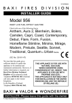
5133239-02 INSTALLER AND OWNER GUIDE Model 820 Electric Heater Fitted with one of the following fascia. Blenheim Seattle or GC No. EF-032-33 This guide is intended to help you install and care for your Valor Fires electric heater. Please read carefully before installing and using your heater. However, if further information is required, our Valor Fires Technical Helpline will be pleased to help. Telephone 0844 8711 565 (National call rates apply in the United Kingdom). In the Republic of Ireland Telephone 0044 844 8711 565. Important: Please keep your guide in a safe place for future reference. © Baxi Heating U.K. Limited 2010. INSTALLER AND OWNER GUIDE Baxi Heating U.K. Limited 2010. All rights reserved. No part of this publication may be reproduced in any material form (including photocopying), stored in any medium by electronic means (including in any retrieval system or database) or transmitted, in any form or by any means, whether electronic, mechanical, recording or otherwise, without the prior written permission of the copyright owner. Applications for the copyright owner's permission to reproduce any part of this publication should be made, giving details of the proposed use, to the following address: The Company Secretary, Baxi Heating UK Limited, The Wyvern Business Park, Stanier Way, Derby, DE21 6BF. Warning: Any person who does any unauthorised act in relation to a copyright work may be liable to criminal prosecution and civil claims for damages. CUSTOMER CARE Thank you for choosing Valor Fires All Valor Fires heaters are designed to meet the most stringent quality, performance and safety requirements to provide our customers with many years of trouble free service. This guide aims to improve your understanding and appreciation of your new Valor Fires heater, by providing simple and informative instructions to enable you to install it and to ensure that you benefit from the excellent performance and features it has to offer. If you require further assistance, the Valor Fires Technical Helpline will be pleased to help. Please telephone 0844 8711 565 (local rates apply in the United Kingdom). In the Republic of Ireland please telephone 0044 844 8711 565. Valor Fires, Erdington, Birmingham B24 9QP www.firesandstoves.co.uk Because our policy is one of constant development and improvement, details may vary slightly from those given in this publication. © Baxi Heating U.K. Limited 2010. Page 2 INSTALLER AND OWNER GUIDE Safety First. Valor Fires heaters are CE Approved and designed to meet the appropriate British Standards and Safety Marks. Quality and Excellence. All Valor Fires heaters are manufactured to the highest standards of quality and excellence and are manufactured under a BS EN ISO 9001 quality system accepted by the British Standards Institute. 1. HANDLING AND UNPACKING Before continuing any further with the installation of this heater please read the following: Important safety instructions. The approximate lifting weights (kg) of the heater parts are listed below: Model Blenheim Seattle Heat engine 5.44 5.44 Firefront 4.58 0.91 Fascia 0.63 0.63 Spacer* 1.3 1.3 Fuel effect 0.72 0.9 * An optional spacer frame kit is obtainable either from the your heater supplier or direct from Valor Fires Sales. The kit is a 75mm (3 inch) spacer kit (Kit number 05801T1). One person should be sufficient to lift the heater. If for any reason this weight is considered too heavy then obtain assistance. When lifting always keep your back straight. Bend your legs and not your back. Avoid twisting at the waist. It is better to reposition your feet. Avoid upper body/top heavy bending. Always bend from the knees rather than the waist. Do not lean forward or sideways whilst handling the heater. Always grip with the palm of the hand. Do not use the tips of fingers for support. Always keep the heater as close to the body as possible. This will minimise the cantilever action. Use gloves to provide additional grip. Always use assistance if required. © Baxi Heating U.K. Limited 2010. Page 3 INSTALLER AND OWNER GUIDE 2. SAFETY This appliance is not intended for use by persons (including children) with reduced physical, sensory or mental capabilities, or lack of experience and knowledge, unless they have been given supervision or instruction concerning use of the appliance by a person responsible for their safety. Children should be supervised to ensure that they do not play with the appliance. Always Always install the heater in accordance with this guide. If in doubt obtain expert advice. Always make sure the electrical socket is accessible and located adjacent to, but not above the heater. Always disconnect the heater from the electrical supply before carrying out cleaning or maintenance. Always make sure the heater is firmly secured to prevent it from being tipped over. Always use a fireguard when young children, infirm persons and pet animals can come into contact with the heater. Always use genuine Valor Fires spare parts. Never Never leave children unsupervised in a room where the heater is ON and unguarded. Never obstruct or cover the fan outlet or force items into heater openings. Never install or use the heater anywhere where water is in use, i.e. Bathrooms, Kitchens, Shower Rooms, Swimming Pools etc. Never use aerosols or steam cleaners on or around the heater. Never route the electric supply cable under carpet etc. Never install the heater close to curtains or combustible materials. Never use the heater to dry clothes etc. Never sit or stand on the heater. Never use the heater with a timer switch or similar device. Important electrical safety. The heater must not be located in front of or under an electrical socket; the socket must always be accessible in order to disconnect the heater from the electrical supply for maintenance and cleaning. © Baxi Heating U.K. Limited 2010. Page 4 INSTALLER AND OWNER GUIDE CAUTION: In order to avoid a hazard due to inadvertent resetting of the thermal cut out, this appliance must not be supplied through an external switching device, such as a timer, or connected to a circuit that is regularly switched on and off by the utility. Important! This heater must be earthed. The heater is supplied with a 3 pin 13 Amp fused re-wireable plug with 1mm² 3 core cable. The wires in the cable are coloured in accordance with the following code: Live = Brown Neutral = Blue Earth = Green / Yellow The electric cable must be safely routed from the heater to an electrical socket. If the electric cable is damaged, to avoid a hazard it must be replaced by a Valor Fires authorised service agent, or similarly qualified person (See the last page of this guide for useful telephone numbers). All external wiring between the heater and the electrical supply shall comply with current IEE regulations. Extension leads should not be used. © Baxi Heating U.K. Limited 2010. Page 5 INSTALLER AND OWNER GUIDE 3. FITTING THE HEATER The installation of this heater requires a reasonable level of DIY skills. Please read this guide thoroughly before commencing installation and if in doubt, seek help from a competent person. Important: Before continuing with the installation of this heater please ensure that you have completed the information on the last page of this guide. Do I need any tools? 1. Depending upon the chosen method of installation you may need the following screwdrivers: A Pozidrive / Phillips / cross head. This should have a number 2 size tip. A Flat end. 2. If drilling into brickwork you will need a power drill (preferably with hammer action) and appropriate size drill bit for the wall plugs supplied. Where can I fit the heater? This heater can be fitted into fireplaces or surrounds where the following dimensions are available. Width Height Depth 400mm - 450 mm (15.35 inches - 17.72 inches) 555mm - 590 mm (21.9 inches - 23.2 inches) At least 75mm (At least 3 inches) An optional spacer frame kit is obtainable either from the your heater supplier or direct from Valor Fires Sales. The kit is a 75mm (3 inch) spacer kit (Kit number 05801T1). Moving the cable guide. At the base of the heater you will find an electric cable which runs through a rectangular plastic cable guide. As supplied the cable guide is fitted into the rectangular cut-out on the right side of the heater. If required, the cable guide can be removed and put in the rectangular slot in the centre or left hand side of the heater. For removal and fitting please see the following sections. Removing the cable guide 1. Before removing the cable guide please note that the wider part of the cable guide is on the outer edge of the base (See figure 1- Item 1). 2. To remove the cable guide push and lift the tab on the bottom. The bottom of the cable guide will open (See figure 1- Item 2). 3. Lift the electric cable clear of the cable guide. © Baxi Heating U.K. Limited 2010. Page 6 INSTALLER AND OWNER GUIDE 4. Hold the bottom of the cable guide close to the heater then gently pull the cable guide away from the rectangular slot (See figure 1- Item 3). Fitting the cable guide. When fitting the cable guide please remember that the wider part of the cable guide has to be fitted against the outer edge of the base (See figure 1- Item 1). 1. Gently pinch the sides of the cable guide (See figure 1 - Item 4) and push the cable guide into the required rectangular slot. 2. Place the electrical cable into the guide and close the top of the cable guide. Item 1 Item 3 Item 2 Item 4 Figure 1. Removing and positioning the cable guide. Removing the fascia 1. Very strong magnets attach the fascia to the heater. Support the rear of the heater and gently pull the fascia forward (See figure 2). 2. Keep the fascia in a safe place while installing the heater. Figure 2. Removing the fascia. © Baxi Heating U.K. Limited 2010. Page 7 INSTALLER AND OWNER GUIDE Heater fixing. All fixings supplied with the heater have been identified in figure 3. Contents Quantity Heater 1 Wall plug 5 Wood screw 4 Eye screw 1 Steel wire 1 No.8 x 3/8 Screw 4 M4 x 25mm Screw 2 Washer 2 Diffuser 1 Control Knob 1 (Illustrations are not to scale) Figure 3. Contents. Fascia not shown (Items are not to scale) © Baxi Heating U.K. Limited 2010. Page 8 INSTALLER AND OWNER GUIDE Fitting the Control Knob. The control knob is supplied separately with the accessory pack. Fit the control knob before continuing with the heater installation. To assemble the control knob to the control spindle, firstly line up the ‘D’ profile on the underside of the control knob to the ‘D’ profile on the spindle (both flats should line up). Place the control knob onto the spindle and gently push until the control knob is fully located. Figure 4. The heater must be fixed into position to prevent it from being tipped over The following fixing options are available: Screw Fixing. Wire Fixing. Spacer Frame*. * An optional spacer frame kit is obtainable either from the your heater supplier or direct from Valor Fires Sales. The kit is a 75mm (3 inch) spacer kit (Kit number 05801T1). If fitting the heater into a fireplace or surround opening, try the heater in the opening to ensure that it will fit. If fitting the heater onto a decorative hearth surface such as marble or tile it is advisable to protect the hearth surface. Do not drag the heater across the surface of the hearth as this may scratch the hearth surface. Method A - Screw fixing. Note - If fixing to marble it is recommended that Method B - ‘Wire fixing’ is used. Drilling marble without the correct tools and experience may result in the marble cracking. 1. Place the heater into the fireplace or surround opening. Make sure that the heater is in the middle of the surround or fireplace. 2. There are two slotted holes in the top of the heater (See figure 5). Mark through the slotted holes so that their position is clear when the heater is removed. 3. Remove the heater. 4. Drill an appropriate size hole in each of the Figure 5. Slots for screw fixing. © Baxi Heating U.K. Limited 2010. Page 9 INSTALLER AND OWNER GUIDE marked positions. Insert wall plugs into the drilled holes. 5. Place the heater so that the slotted holes are in line with the wall plugs in the fixing surface. 6. Screw and secure the heater with two wood screws (See figure 3). Method B - Wire fix. This method of fixing needs a fireplace opening and is recommended when fixing the heater to a marble surround or where the wall or brickwork is in poor condition. 1. The fixing kit supplied with the heater includes a steel wire and eyescrew (See figure 3). These can be used to secure the heater to the back of a Figure 6. Eyescrew position. fireplace opening. 2. Mark the eyescrew position on the centre line at the back of the fireplace opening and at a height of 533-560mm (21 inches - 22 inches) (See figure 6). 3. Drill an appropriate size hole in the marked position. 4. Insert a wall plug into the drilled hole. 5. Screw the eyescrew into the wall plug. 6. Position the heater in front of the fireplace opening. 7. At the top of the heater there are four small holes, two each side of the heater (See figure 7 - Item 1). From the front of the heater, thread about 50mm ( 2 inches) of the steel wire into the inside small hole on the left side of the heater (See figure 7 - item 2). 8. Thread the other end of the wire through the remaining small hole on the left hand side of the heater. Continue to push the wire through this hole until there is only a small loop of Figure 7. Steel wire fixing (Detail at top of heater may differ from that shown) wire at the front of the heater (See figure 7 - item 3). © Baxi Heating U.K. Limited 2010. Page 10 INSTALLER AND OWNER GUIDE 9. At the back of the heater there will be a long piece and a short piece of wire coming through the two holes. Hold the short piece and give the long piece a gentle tug. This will secure the steel wire. Take the long piece and thread this through the eyescrew in the back of the fireplace opening (See figure 7 - item 4). 10. From the back of the heater thread the long piece of steel wire through the outer small hole on the right hand side of the heater (See figure 7 - item 5). 11. Locate the heater in the fireplace opening, then from the front of the heater, gently pull the steel wire on the right hand side to gather up the excess until the heater is secure. Thread the wire through the remaining small hole to lock the wire and heater in place (See figure 7 - item 6). Method C - Spacer Frame The optional spacer frame is for use during installations where a chimney recess or rebated fire surround are not available. For your safety the frame and heater must be securely fixed to the rear wall. Fitting the spacer frame The rear of the spacer has two screw location slots in the top flange. These should be to the rear when fitting. 1. Position the spacer frame against the wall. Ensure that the spacer frame is central to the fireplace. 2. The top rear flange of the spacer frame has two screw locations. Mark the positions of the two screw locations on the rear wall (See figure Figure 8. Location points 8). 3. Remove the spacer frame from the fireplace and place away from the work area. 4. Drill the screw locations using a suitably sized masonry drill bit for the wall plugs supplied. 5. Insert two wall plugs provided into the holes. 6. Insert a wood screw into each hole and screw in until there is approximately 6mm of screw protruding from the wall. Preparing the heater for installation. 1. Ensure that the decorative front surround has been removed from the heater as described earlier in this guide. 2. Using the four No.8 x 3/8 screws provided, fix the heater to the spacer frame. 3. There is a supply cable slot on both sides of the spacer frame. It is located at the base. Decide which side to pass the supply cable through and position the supply cable in the spacer frame slot (See figure 9). Figure 9. Locating the cable © Baxi Heating U.K. Limited 2010. Page 11 INSTALLER AND OWNER GUIDE Fitting the heater. 1. Locate the spacer frame and heater over the screw heads ensuring a tight fit. If the fit is loose, remove the spacer frame and heater from the wall. Tighten the wall screws slightly and reposition the spacer frame and heater. Fitting the light diffuser. 1. There is a light diffuser supplied with the heater (See figure 3). Place this on to the metal flange below the plastic screen (See figure 10). Figure 10. Diffuser location Fitting the Fascia Blenheim model. 1. Removing the fascia trim may have moved the magnets used to fix it to the heater. The magnets should be located as in figure 11. 2. Locate the fascia onto the heater. Ensure that the sides of the fascia sit on the floor / hearth. 3. There are two hanging screws on the rear of the firefront. Locate these into the slots as in figure 12. 4. Place the one piece fuel effect on top of the firefront fuel support. Figure 11. Figure 12. Firefront location © Baxi Heating U.K. Limited 2010. Page 12 INSTALLER AND OWNER GUIDE Seattle model. 1. With the fascia trim removed, unscrew and remove the two screws from the lower right hand side of the heater (See figure 13) then align the four holes in the firefront assembly with those on the heater (See figure 14). Secure with the two screws removed previously and two screws supplied. 2. Removing the fascia trim may have moved the magnets used to fix it to the heater. The magnets should be located as in figure 11. 3. Place the one piece fuel effect on top of the firefront fuel support. Figure 13. Figure 14. © Baxi Heating U.K. Limited 2010. Page 13 INSTALLER AND OWNER GUIDE 4. USING THE HEATER Important Safety Never cover the heater or obstruct the openings at the base of the heater, this could cause overheating and consequent risk of fire. Figure 15. Controls What are the three switches for? The heater is operated by three switches located below the hood on the left hand side of the heater. Switch 1 = Main On - Off. (In the ‘ON’ position, only the flame effect operates) Switch 2 = 1kW fan heat setting and flame effect. (Switch 1 needs to be in the ‘ON’ position to enable switch 2 to operate). Switch 3 = 2kW fan heat setting and flame effect. (Switches 1 & 2 need to be in the ‘ON’ position to enable switch 3 to operate). What is the knob for? The heater has a variable energy control located below the hood on the right hand side of the heater. The variable energy control will only work when all three switches are on. If the room requires maximum heat, rotate the control fully clockwise. For less heat rotate the control counterclockwise until the required heat setting is achieved. When operating the variable energy control will operate between the 1kW and 2kW settings. Turning the knob fully counterclockwise will switch the variable energy function off. © Baxi Heating U.K. Limited 2010. Page 14 INSTALLER AND OWNER GUIDE 5. CLEANING AND MAINTAINING THE HEATER How do I clean my heater? The heater fascia and plastic parts need only to be wiped clean with a dry soft cloth, do not use polishes or abrasive materials. The Seattle heater may have fingerprints on the fascia surface. These can be removed by applying a small amount of ‘baby oil’ to a lint free non-abrasive cloth and wiping the surface. Use a clean cloth to remove the oil. I have a problem with my heater! Important Safety Before undertaking maintenance always disconnect the heater from the electricity supply by removing the 3 pin plug and allowing the heater to cool completely. 1. My heater is on but there is no light or heat. The first thing to do is check the wall socket. To do this plug in a known working appliance. If the appliance you have plugged in works then there is a good chance that the problem lies with the 13 Amp fuse in the heater plug. If either fuse or socket is suspected, have them checked by an electrician. 2. My heater is on but there is no heat. A cut out device is fitted to the heater to prevent damage due to over heating. If it operates due to an obstruction in the airflow, the heater must be turned off and allowed to cool for 15 minutes and the obstruction removed before restarting. 3. I Have a problem that is different to those in the previous examples 1- 3. For general advice about your heater call: Valor Fires TECHNICAL HELPLINE 0844 8711 565. CALLERS IN THE REPUBLIC OF IRELAND Call 0044 844 8711 565 What should I do when I’m ready to dispose of my heater? The plug should be removed from the mains cable and the mains cable cut from the heater. These should be disposed of with the heater. Environmental Protection. Waste electrical products should not be disposed of with household waste. Please recycle where facilities exist. Check with your local authority or retailer for recycling advice. © Baxi Heating U.K. Limited 2010. Page 15 INSTALLER AND OWNER GUIDE 6. WARRANTY AND SERVICE Information for the customer Standard Warranty Terms & Conditions The warranty is for 12 months subject to contract. In the United Kingdom servicing can be carried out either by a heateam service engineer or a suitably qualified person. You must register your heater with heateam, the service division of Baxi Heating UK Limited, either by completing and returning the registration card or calling our free telephone registration line on 0800 032 72 44. Our promise to you If you experience a fault with your new heater, we aim to provide a safe and high quality repair service supported by our dedicated national network of highly skilled engineers. Nothing in this warranty will affect your statutory rights. What you need to do if you experience a problem with the operation of the heater; Read section 5 of this guide “Cleaning and maintaining the heater”. If the problem cannot be resolved simply call our service division heateam on 0844 8711 565 to book an engineer visit or for any general advice that you may need. Our contact centre is open Monday to Friday 8am – 6pm, weekends and Bank Holidays 8.30am – 2pm, excluding Christmas Day and New Years day. When calling heateam, it would be helpful if you could have the following information to hand:1. 2. 3. 4. Heater serial number.* Heater brand and model number.* Date of installation.* Proof of purchase (If you do not have the heater serial number) *Note: Details 1 – 3 can be found on the last page of this guide. What this warranty covers Free of charge repair or replacement of components found to be of faulty manufacture. Free of charge replacement of the complete unit providing the failure is related to a manufacturing fault that cannot be repaired or is uneconomic to repair. © Baxi Heating U.K. Limited 2010. Page 16 INSTALLER AND OWNER GUIDE What this warranty does not cover Repairs to heaters which haven’t been installed properly and as set out in this guide. Faults caused by inadequate supply of electricity. Reimbursement of any third party repair or replacement costs that we haven’t been told about or agreed with you in advance. Compensation or consequential losses (e.g. loss of earnings, business losses, stress and inconvenience) arising from a production breakdown, including repair delays caused by factors outside our reasonable control. © Baxi Heating U.K. Limited 2010. Page 17 INSTALLER AND OWNER GUIDE © Baxi Heating U.K. Limited 2010. Page 18 INSTALLER AND OWNER GUIDE To be completed by the customer: Model 8 2 0 Serial number (Can be found on the information label - See figure 16) A LABEL CONTAINING THE SERIAL NUMBER MAY HAVE BEEN PLACED INSIDE THIS BOX. Fascia name (Block Capitals) Fascia code - Can be found close to the information label (Block Capitals) A LABEL CONTAINING THE FASCIA CODE MAY HAVE BEEN PLACED INSIDE THIS BOX. Brand (Please tick) Baxi Valor Wonderfire Other................. Date of Installation D D M M Y Y Figure 16 © Baxi Heating U.K. Limited 2010. Page 19 © Baxi Heating U.K. Limited 2010.