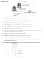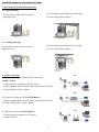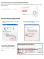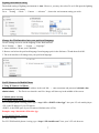
1
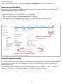
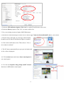
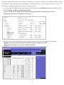
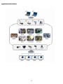
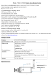
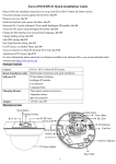
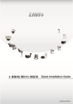
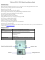
TAZavio P5110 / P5115 Quick Installation Guide Installation Steps Please follow the installation steps below to set up your P5110 / P5115 Day/Night Pan/Tilt IP Camera. Check the package contents against the list below. See P.1 Physical Overview. See P.2 Install the hardware and connect all cables. See P.3 Microsoft OS: Use the software CD to install Intelligent IP Installer. See P.4 Access the IP Camera using Intelligent IP Installer. See P.4 Mac OS Using Safari Browser. See P.6 Change lighting environment setting. See P.7 Change the Web Interface into your preferred language. See P.7 Use IP Camera via Mobile Phone. See P.7 Wireless Setting.( P5115 Model ). See P.8 Windows Live Messenger Setting. See P.8 Access to Internet via Static IP, Dynamic IP or both. See P.10 Application of IP Camera See P.12 For more information, please check the User Manual available in the Software CD or you can download the latest software from http://www.zavio.com Package Contents Camera P5110 / P5115 Day/Night Pan/Tilt IP Camera Quick Installation Guide Brief product information and quick installation Software CD IP Surveillance Software Intelligent IP Installer User Manuals Language Packs Component Pack Bracket, two packs of screws , Antenna (P5115 model) Adaptor 12V DC, max 12W Quick Installation Guide Software CD Camera Component Pack 1 Physical overview Focus Adjustment Ring - Adjust focus manually to achieve the best image quality Infrared LEDs - Infrared LEDs for night use up to 15 working distance Wireless Antenna (for P5115) - For connection of IEEE 802.11 b / g wireless network. Built-In Microphone - Built-In Microphone for Two-way Audio Network LED indicator - Network LED will light up after connecting with network. Power LED indicator - Power LED will light up after completing the boot process. Power Connector - For connection of 12V DC input. Reset - When the device is empowered, press the Reset Button to reboot the device, or hold the Reset Button for 10 seconds to set the device settings back to factory default Audio In -To support audio in with Microphone for two way audio Audio Out - To support audio out with earphones or speakers for two way audio Network Connector - For connection to the Ethernet via RJ-45 standard with PoE I / O Terminal Connector - 1Input / 1Output to support External Alarm and Sensor used for motion detection, event triggering and alarm notification…etc. DI / DO Terminal connector diagram - Please refer the following illustration below for connection method: 2 Install the hardware and connect all cables a. Wall mounting and Ceiling mounting a 1. Wall mounting Fix the camera to the bracket with two supplied screws. Fix the camera and bracket to the wall using two screw and plastic anchors. a 2. Ceiling mounting Fix the camera to the bracket with two supplied screws. Fix the camera and bracket to the ceil using two screw and plastic anchors. b. Connect all cables b1. Without Power over Ethernet (PoE) connection b1 (P5110 / P5115) - Connect the power adaptor to the IP Camera. - Using a standard RJ-45 network cable, connect the IP Camera to a normal Hub / Switch / Router. b2 b2. Power over Ethernet (PoE) (P5110 Model ) - Using a standard RJ-45 network cable, connect the IP Camera to a PoE-enabled Hub / Switch / Router. b3 b3. Wireless connection (P5115 Model ) - Connect the power adaptor to IP Camera. - Connect to Wi-Fi. 3 Microsoft OS: Use the software CD to install Intelligent IP Installer Power on your PC and insert the CD-ROM. The setup page will show up automatically. Please follow those steps to install the firmware. Select “Intelligent IP Installer” and follow Access the IP Camera using Intelligent IP Installer 1. Before using Intelligent IP Installer, please check two setting. b. Browser’s Internet Properties → Privacy → Uncheck Pop-up Blocker a. Browser’s Internet Properties → Security → Default Level 2. Click the Intelligent IP Installer Icon on your desktop. The main page will show up listing all active camera and video server devices. Select the relevant IP camera from the list and click Link to IE. 4 3. Enter your Username and Password to login to the IP Camera. (Default is admin / admin) 4. When accessing the IP Camera for the first time, a yellow information bar appears below the address bar: This website wants to install the following add-on: ‘AxvideoView.cab from ‘Zavio Inc’. 5. Click the information bar, and select Install ActiveX control. 6. Click Install. 7. Live view displays in the centre of your web browser. 5 Mac OS using Safari Browser 1. Select Safari icon 2. Click Bonjour function and select the camera you wish to access. 3. Enter name and password to login to the IP camera. (Default is admin / admin) 4. The monitor image will be displayed in your browser. 6 Lighting environment setting The default setting of lighting environment is Auto. However, you may also select 50 or 60 Hz upon the lighting environment of your country. Go to “Setting → Basic → Camera → Advance", choose the environment setting you wish. Change the Web Interface into your preferred language Use the settings screen to set the language of the Web Interface. Go to “Setting → Basic → System → Language”. 1. Insert Software CD into your CD-ROM. 2. Browse and select the preferred language from language pack in the Software CD and then click OK. 3. The web interface will change into your preferred language. Use IP Camera via Mobile Phone 1. Using IP Camera via iPhone Select Safari function → Enter IP address in the web link → enter username and password (default value admin/admin) → The Zavio user interface and Live Image will show up in the middle of the screen. 2. Mobile phone viewing a. 3G Mobile Phone Streaming Viewing For 3G mobile phone viewing, please type “ rtsp://<IP>:<PORT>/video.3gp ” into your 3G web media player. <IP> is the IP address of your IP camera; <PORT> is the RTSP port of your IP camera (Default value is 554.) Example: rtsp://100.10.10.1:554/video.3gp b. 2.5G Mobile Phone Viewing b1. WAP viewing For 2.5G WAP mobile phone viewing, type “ http://<IP>/mobile.wml ” into your 2.5G web browser. 7 b2. Browser viewing For 2.5G mobile phone browser viewing, type “http:// <IP>/mobile.htm ” into your 2.5G web browser. Wireless Setting (P5115 Model) Power the IP Camera and connect an Ethernet network cable to the IP Camera’s LAN port. Using Intelligent IP Installer and entering the camera’s setting page. Please go to “Setting → Basic → System → Network → Wireless”, set the wireless option to “On” 1. Click Refresh and choose the Access Point you wish to connect. 2. Enter the password within the Active transmit key field if required. 3. Choose DHCP to connect through a dynamic IP or assign a static IP for the wireless connection. 4. Click “OK” to apply settings. The Wireless IP address appears in the IP address field. Note: The wireless private IP address can be found in Intelligent IP Installer. Wireless IP address Windows Live Messenger Setting Live video of the IP Camera can be displayed using Microsoft Live Messenger, while providing its public IP address to users for access via the web browser. This feature is useful especially when the IP address of the camera is dynamically assigned. If you wish to set up MSN Messenger, enter the camera’s setting page. Go to “Setting → Basic → System → Network → Messenger”, set the Messenger option “On.” Then, follow the below steps: 1. Create a new MSN Messenger account (e.g.: [email protected]) for the IP Camera. 8 2. Enter the new MSN Messenger Login Account and Password within the designated boxes. 8 3. Under the IP Notification Option, Click “On” to enable IP notification to the users. 4. Under the Privacy Option, Click “On” to create an allow list. 5. Use your existing account to login to MSN Messenger. 6. Add the new MSN Messenger account for IP Camera (e.g.: Camera at [email protected]) to your contact 7. The IP Camera will send you a message with its Public IP and Private IP if the IP Notification Option is enabled. 8. Click on the small camera icon. Then, choose “View a new contact's webcam”. 9. The IP Camera automatically accepts your invitation and its live video is displayed. 10. Click Action button and choose Start control panel to use control panel. 11. You can use Snapshot, Image Setup and PT Control function via MSN add-in control panel. 9 Access to the Internet a. Internet connectivity of the IP camera can be established by inputting the cameras IP information within the Information section. (Please go to Setting → Basic → Network→ Information) b. Internet Connectivity of the IP Camera can be established through PPPoE (Point-to-Point Protocol over the Ethernet) by inputting the username and password from your Internet Service Provider (ISP) within the PPPoE section. (Please go to Setting → Basic → Network→ PPPoE) Note 1: Please reboot the IP Camera, after changing the PPPoE settings. Note 2: Please turn on the DDNS and IP Notification function when using the PPPoE function. 10 c. Internet Connectivity of the IP Camera can be established if your router is UPnP (Universal Plug and Play) enabled. The IP camera is automatically detected and added to “My Network Places” on your computer. Please note that only Home Routers manufactured after 2006 support the UPnP function. c1. If your router is a UPnP Internet Gateway Device (IGD), turn on the UPnP function within the UPnP section. (Please go Setting → Basic → Network→ UPnP) Note: If you turn on the UPnP Port Forwarding function, RTSP (Real Time Streaming Protocol) Port information will change to the illustrated value below. c2. If your router is not a UPnP Internet Gateway Device, please setup Port Forwarding or Port Mapping Note 1: Home Routers manufactured before 2006 do not support UPnP IGD function. Note 2: Enterprise Routers do not support UPnP IGD function. 11 Application of IP Camera 12 Memo ………………………………………………………………………………….. ………………………………………………………………………………….. ………………………………………………………………………………….. ………………………………………………………………………………….. ………………………………………………………………………………….. ………………………………………………………………………………….. ………………………………………………………………………………….. ………………………………………………………………………………….. ………………………………………………………………………………….. ………………………………………………………………………………….. ………………………………………………………………………………….. ………………………………………………………………………………….. ………………………………………………………………………………….. ………………………………………………………………………………….. ………………………………………………………………………………….. ………………………………………………………………………………….. ………………………………………………………………………………….. ………………………………………………………………………………….. ………………………………………………………………………………….. ………………………………………………………………………………….. ………………………………………………………………………………….. ………………………………………………………………………………….. ………………………………………………………………………………….. ………………………………………………………………………………….. …………………………………………………………………………………..