1
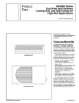
38BNB,BNE/
40BNB,BNE018-030
Duct Free Systems
Installation, Start-Up and Service Instructions
CONTENTS
SAFETY CONSIDERATIONS
.........................
GENERAL .........................................
INSTALLATION
...................................
40BNB,BNE Indoor Unit Installation .................
38BNB,BNE Outdoor Unit Installation
...............
Power Supply ........................................
Leak Test ............................................
START-UP ..........................................
System Checks .....................................
CARE AND MAINTENANCE .........................
38BNB,BNE Outdoor Units .........................
40BNB,BNE Indoor Units ...........................
To Clean the Indoor Unit Front Panel ...............
To Clean Indoor Coil ................................
Air Filters for 38BNB,BNE Outdoor Units and
40BNB,BNE
Indoor Units .........................
SERVICE ...........................................
TROUBLESHOOTING
............................
SAFETY
Page
1
1-4
4- l 1
4
(r
7
7
12
12
12
12
12
12
12
12
12
13-16
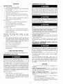
CONSIDERATIONS
Installing, stalling up, and servicing air-conditioning equipment can be hazardous due to system pressures, electric_d
components,
and equipment location (roofs, elevated structures, etc.).
Only trained, qualified installers and service mechanics
should install, start-up, and service this equipment.
Untrained personnel can perform basic maintenance functions such as cleaning coils. All other operations should be
performed by trained service personnel.
When working on the equipment, observe precautions in
the literature and on tags, stickers, and labels attached to the
equipment.
Follow all safety codes. Wear safety glasses and work
gloves. Keep quenching cloth and fire extinguisher
nearby
when brazing. Use care in handling, rigging, and setting bulky
equipment.
IMPORTANT:
separately.
•
•
•
•
•
•
•
Both
refligerant
lines must be insulated
Consult
local building
codes and National
Electrical
Code (NEC, U.S.A.) for special installation requirements.
Control wiring should be 18 gage.
Use only type "G" or"C" fuses.
Use single length power cable without extension.
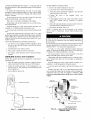
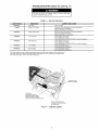
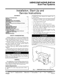
Allow sufficient space for airflow clearance on condensing units for wiring, refrigerant
piping, and servicing
unit. See Fig. 1 and 2 for minimum required distances
between unit and walls or ceilings.
Indoor and outdoor units should be installed at a minimum of 10 ft apart. Maximum line length is 130 ft, and
vetlical separation is 66 ft.
Do not install indoor units near a direct source of heat
such as direct sunlight, steam or flame.
Do not bury more than 36 in. of refrigerant pipe in the
ground. If any section of pipe is buried, there must be a
6 in. vetlical rise to the valve connections on the outdoor
units. If more than the recommended
length is buried,
refrigerant may migrate to the cooler buried section during
extended periods of system shutdown. This causes refrigerant slugging and could possibly &image the compressor at
start-up.
6"
(0.15m)
MIN.
6"
(o.15m)
MIN.
Before installing or servicing system, always turn off main
power to system and install lockout tag on disconnect.
There may be more than one disconnect switch. Electrical
shock can cause personal injury.
2'
(0.6m)-
GENERAL
These instructions covet the installation, start-up and setvicing of 38BNB,BNE018-030
outdoor and 40BNB,BNE018-030
indoor units cooling only and heat pump duct free systems. See
Table 1 for parts included. See Tables 2 and 3 for Physical Data.
System
Requirements
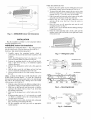
Fig. 1 -- 38BNB,BNE Outdoor Unit Clearances
and
3.
IMPORTANT:
See line sizing requirelnents
Manufacturer
in Tables 2
reserves the right to discontinue, or change at any time, specifications
PC 111
Catalog No. 533-80122
Printed in U.S.A.
or designs without notice and without incurring obligations.
Form 38B/40B-4SI
Pg 1
5-05
Replaces: 38B/40B-1SI,
38B/40B-2SI
I
]
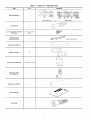
Table 1 -- Parts List -- High Wall Units
ITEM
QTY
DIAGRAM
Main Screw
Mounting
Bracket
38B/40B018-024
Long Screws
1/2 in. Cap Screws (size
units only)
030
Cushions
2 colored, 2 nickel
plated
1
4
Electric Terminals
16
Remote Controller Rack
1 rack with 2 screws
Remote Controller
and Batteries
Insulation for Fittings
Owner's Manual
Wall Plugs
38B/40B030
8
Outdoor Sensor
Connecting
Cable
Absorption
or
__
_
:,_
(HEAT PUMP ONLY)
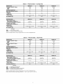
Table 2 i
INDOOR UNIT
40BNB-024
40BNB-030
22,800
10.5
9.5
28,000
10.0
9.1
3.1
3.8
4.7
5.0
7.0
8.0
726
726
700
11.63 x 42.50 x 7.28
11.63 x 42.50 x 7.28
12.0 x 55.0 x 7.5
28.0
28.0
68.0
NET WEIGHT (Ib)
OUTDOOR UNIT
TUBE CONNECTIONS
Mixed Phase...Suction
(in.)
Vert Lift/Vert Drop/Max Length (ft)
NOMINAL LINE SIZING
Mixed Phase...Suction
(in.)
DIMENSIONS
H x LxW(in.)
Only
18,000
10.0
9.6
(Ib)*
MOISTURE REMOVAL (pt/hr)
AIRFLOW
High Cfm
DIMENSIONS
H x L x W (in.)
Cooling
40BNB-018
COOLING CAPACITY (Btuh)
SEER
EER
SYSTEM CHARGE
Physical Data i
21.25
38BNB-018
38BNB-024
38BNB-030
1/4...1/2
66/66/130
3/8...S/8
66/66/130
3/8...S/8
66/66/130
1/4...1/2
3/8...5/8
3/8...5/8
X 28.75
X 10.44
25.18
84.5
NET WEIGHT (Ib)
X 35.44
X 12.28
145.0
25.38
X 45.0
X 15.88
165.0
LEGEND
EER
-SEER --
Energy Efficiency Ratio
Seasonal Energy Efficiency
Ratio
*Units are shipped with a factory charge based on 10 to 50 ft of refrigerant
Table 3 i
INDOOR UNIT
lines.
Physical Data i
Heat Pump
40BNE-018
40BNE-024
40BNE-030
COOLING CAPACITY (Btuh)
SEER
EER
18,000
10.0
9.6
22,800
10.5
9.5
28,000
10.0
9.1
HEATING CAPACITY (Btuh)
HSPF
COP
18,600
6.8
2.9
22,800
7
2.8
28,000
7.0
2.8
3.1
3.8
4.7
5.0
7.0
8.0
726
726
700
295 x 1020 x 185
295 x 1020 x 185
304 x 1397 x 191
28
28
44
SYSTEM CHARGE*
(Ib)
MOISTURE REMOVAL (pt/hr)
AIRFLOW
High Cfm
DIMENSIONS
H x L x W (in.)
NET WEIGHT (Ib)
OUTDOOR UNIT
TUBE CONNECTIONS
Mixed Phase...Suction
(in.)
Vert Lift/Vert Drop/Max Length (ft)
NOMINAL LINE SIZING
Mixed Phase...Suction (in.)
DIMENSIONS
H x L x W (in.)
SHIPPING WEIGHT (Ib)
COP
EER
HSPF
SEER
-----
38BNE-018
38BNE-024
38BNE-030
1/4...1/2
66/66/130
3/8...5/8
66/66/130
3/8...5/8
66/66/130
1/4...1/2
3/8.-5/8
21.25 x 28.75 x 10.44
25.18 x 35.44 x 12.28
25.38 x 45.0 x 15.88
84.5
145.0
165.0
LEGEND
Coefficient of Performance
Energy Efficiency Ratio
Heating Seasonal Performance Factor
Seasonal Energy Efficiency Ratio
*Units are shipped with a factory charge based on 10 to 50 ft of refrigerant
NOTE: Standard Ambient Operating
3/8.-5/8
lines.
Limitations -- 55 F to 125 F (12.7 C to 51.6 C).
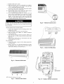
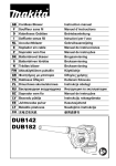
WIRE
6" (0.
THE
INDOOR
UNIT
1. Remove
the unit's grille insell by lilling
and pulling it gently outward and upward.
_ min.
2.
To remove
018-024)
opening.
3.
4.
the grille
5.
covet
See
Fig.
Once all covers
are off. mount
mounting
bracket. See Fig. 9.
Route
the
(size
8. Save
the
screws
the
onto
the
off until after
interconnecting
outdoor
sensor cable
of the indoor unit.
Fig. 2 -- 40BNB,BNE Indoor Unit Clearances
the two screws
Pull downwards
and outwards
on the bottom of the grille
and gently raise the frame off file top of the unit.
Remove
the two screws
from file control
box cover
NOTE: Leave covers
Connections
section.
6.
remove
or three screws (size 030) from the _dr discharge
See Fig. 7. Save the screws to reassemble.
and take off the
reassemble.
6'-8'3" (1.8-2.5rn)
frame,
the lower part
See Fig. 6.
unit's
towmd
unit
the Making
electric
the lower
wall
Drainage
cable
right
to
and
hand
the
corner
INSTALLATION
Plan the installation carelhlly
and make inst_dlation easiec
40BNB, BNE Indoor
to avoid component
failures
Unit Installation
REFRIGERANT
LINE ROUTING -- Tile refrigerant lines
may be routed in any of the four directions shown in Fig. 3.
INSTALL THE MOUNTING
BRACKET
1. Carefully
remove
the mounting
bracket,
which is
connected to the back of the indoor unit's metal base with
3 screws.
NOTE: Size 030 units have four I/2 in. cap screws, 2 colored and 2 nickel pkited. Keep these for kiter use.
2. Position the mounting bracket on the wall and level it
using a spirit level (see Fig. 2 for minimum required
clearance distances).
3. Mark the four drilling holes on the wall, as they appear in
Fig. 4.
4. Drill the holes, insert the wall plugs and use four long
screws to attach the mounting bracket to the wall.
5. Check that the bracket is level and securely fastened to
the wall.
4
Fig. 3 -- Refrigerant Lines
38/40BN018-024
-_ i
_"
1i_2_..%
5.
6.
If refrigerant line route no. 1, 3 or4 are used, use a sm_dl
saw blade to cmefully remove the corresponding
plastic
covering on the side panel.
Run the outdoor sensor cable, electrical cable, refrigerant
lines, and drainage tube through the hole.
Fill the remaining wall hole gap wifll an appropriate
sealant material.
Screw
_
_--_
I
:_'.............................
o :n::_ii
2 in, (50 mm)
2.6 in, (65 ram)
-_-[--
"...............
b
38/40BN030
Main
DRILL A HOLE IN THE WALL FOR DRAINAGE
AND
INTER-UNIT CONNECTIONSTo m;&e the connections
between the indoor and outdoor units, drill a 3-in. hole through
the wall for the refrigerant lines, drainage hose and control
cable passage as shown in Fig. 5.
1. Mmk the center °f the h°le t° be diilled acc°rding t° the refrigerant line routing used and dimensions shown in Fig. 4.
2. Make sure to diill outw;uds and downwards, so that the
opening in the outside wall is at least I/2-in. lower than
the opening on the inside.
3. Make sure the drainage hose is at the bottom side of the
hole.
4.
Main
Screw
Z
1.6"(41mm)'
Fig. 4 -- Mounting Bracket
OUTDOOR
SENSOR
REFRIGERANT
3-IN.
MIN
INDOOR
OUTDOOR
CABkE_
ELECTRICAL
CABLE
Fig. 5 -- Drill Holes
LINES
DRAINAGE
TUBE
7.
8.
Strip the cables back 1/4 inch.
Make sure that the wires are connecting in accordance
with the wiring diagram on the inside of the unit front
cover or within this instruction manual.
9. Secure the control cables in the upper strain relief and the
power cables in file lower strain relief.
10. For heat pump systems only, connect the outdoor sensor
TH3 to its mating black terminal. See Fig. 10.
11. For size 030 units only, use the two colored, l/2-in, cap
screws and two nickel plated l/2-in, cap screws to secure
the base of the unit to the bottom of the wall mounting
bracket. Use the colored screws in the screw holes that
will show, and the nickel plated screws on the holes that
are underneath the plastic and will not show.
/
Plastic control cover
Make sure that all wires and screws me firmly fastened.
Ix_ose wires or connections can cause damage and present
a fire hazard.
MAKE
DRAINAGE
Fig. 8 -- Remove Control Cover
CONNECTIONS
1. Connect the unattached end of the drainage tube to the
drainage hose outlet.
2. Se_d the &'ainage connection to prevent leakage.
3. Make sure there me no kinks, "U" bends or flattened
sections in the tube.
4.
Check that the &'ainage limctions properly. Fill the pan
below the unit's coil with water and observe that it freely
drains out.
5.
Make sure the &ainage hose is at the bottom side of the
wall through-hole (see Fig. 5).
REASSEMBLE
1. Connect file display connector
ed circuit board.
2.
to the display panel print-
Put the control box cover and grille fiame back on using
the appropriate screws (Steps 2 and 4 of Wire the Indoor
Unit section). Put the cover insert back on.
Fig. 9 -- Indoor Unit Mounting
Fig. 6 -- Remove Grille Insert
OUTDOOR
(HEAT
PUMP
NOTE: Size 030 unit shown (3 screws).
Fig. 7 --
Remove
Grille
Frame
Fig. 10 -- Outdoor Sensor Connection
SENSOR
ONLY)
CONNECT
REFRIGERANT
LINES -- Connect file ends of
the refrigerant lines to their appropriate fittings, following these
guidelines:
To connect the refrigerant lines use only "L" type sealed,
dehydrated copper refrigerant tubing. No other type of tubing
may be used. Use of other types of tubing will void the manufacturer's warranty.
Do not open service v_dves or remove protective caps from
tubing ends until all the connections are made.
Take care to avoid kinks or flattening of the tubing.
Bend tubing with special bending tools to avoid the formation of sharp bends.
Keep file tubing free of dirt, sand, moisture and other contaminants to avoid &imaging the ret]igemnt system.
Avoid sags in the suction line to prevent the formation
traps.
of oil
Insulate both refrigerant lines sep_uately with 3/3-in. walled
thermal pipe insulation. Inserting the tubing into the insulation
before making the connections can save time and improve insulation. The suction and mixed phase lines should never come
in direct contact.
ATTACH
THE REMOTE
CONTROLLER
RACK
1. Use the two screws supplied with the controller to attach
the rack to the wall in the location selected by the customer (see Fig. 11).
2. [nstall batteries in the remote control.
3.
Place lemote control into remote control rack.
4. For remote control operation, refer to the unit Owner's
Manual.
38BNB, BNE Outdoor
Unit Installation
MAKE WIRING
CONNECTIONS
1. Remove the outdoor unit plastic side covel:
2. Loosen the screws on the terminal block.
3.
4.
Attach the electrical terminals supplied to the inter-unit
control and power cable wires.
Connect
the wires
to the
terminal
block.
See
Fig. 13-16.
5.
For heat pump systems only, connect the outdoor sensor
cable TH3, making
sure the connector
is properly
inserted.
6.
Secure the inter-unit electric and sensor cable to the outdoor unit with the clamp shown in Fig. 12.
7.
Reassemble
the plastic side covel:
NOTE: A &'ainage tube can be connected to the outdoor
unit to lemove condensation
formed during heating mode
operation.
Make sure that _dl screws and wires me properly fastened.
Ix)ose wires or connections can cause damage and present
a fire hazard.
MAKE REFRIGERANT
PIPING CONNECTIONS
DOOR UNIT) -- To connect the refrigerant lines:
(OUT-
Use only "L" type sealed, dehydrated copper refrigerant
tubing. No other type of tubing may be used. Use of other types
of tubing will void the manufacturer's
wm'ranty.
Do not open service valves or remove protective
tubing ends until _dlthe connections me made.
caps from
unit must be installed on a solid surface
Bend tubing with special bending tools to avoid the formation of sharp bends. Take cm'e to avoid kinks or flattening of
the tubing.
1. Place the rubber absorption cushions (supplied with the
outdoor unit) under the unit's legs to prevent vibrations.
Keep the tubing free of dirt, sand, moisture, and other contaminants to avoid &_maging the refrigerant system.
2.
Avoid sags in the suction line to prevent the formation of oil
traps.
Insulate each tube with 3/s-in. w_dled thermal pipe insulation. Inserting the tubing into the insulation before making the
connections
will save time and improve installation.
The
suction and mixed-phase
lines should never come in direct
contact.
NOTE: The outdoor
(mounting base).
3.
Fasten the outdoor unit legs to the mounting base, as
shown in Fig. 12. The cushion goes between the legs and
the mounting base.
Be sure that the unit is level.
POWER
SUPPLY
INTER UNIT
TERMINAL BLOCK
_-REMOTE
CONTROL
\
HIGH/LOW
BARRIER
(HEAT PUMP ONLY)
METAL
CONDUIT
;ONNECTION
PLATE
REMOTECONTROLRACK
BE PUT UNDER EACH LEG
Fig. 11 -- Attach Rack to the Wall
Fig. 12 --
Legs and Mounting
Outdoor Units
Base-
FLARING
AND CONNECTING
1. Remove the protective
REFRIGERANT
LINES
2.
Remove the protective cap from the tubing and cut to the
required length. Be sure that the cut is perpendicular and
clean, without burrs.
3.
Slip the flare nut on the tubing
using standiud flaring tools.
4.
Tighten the nut until resistance is met. Mark the nut and
the fitting. Using a suitable wrench tighten an additiomd
I/4 turn. Use tile following specified torque, according to
connection size:
Mixed-Phase
3. Disconnect the vacuum pump. Unit should maintain
500 microns for 5 minutes.
cap from the flme fitting.
line:
4. Open the mixed-phase valve (small valve) with an Allen
wrench.
Suction line:
I/4-in. -- (12.3 ft-lb)
Open the suction line valve (large valve) with an Allen
wrench.
6.
The outdoor unit is supplied with sufficient R-22 refrigerant for 10 to 50 ft of line set. Add 0.9 oz of refiigemnt for
each additiomd 3 ft of tubing used.
7.
Close the service port caps on the suction
mixed-phase valves.
8.
Make sure that the valves are properly opened. Be careful
not to open them more than required as this may damage
the thread.
9.
Replace the service port cap. Using refrigerant oil, lubricate the cap beam and hand tighten until resistance is met.
Use a suitable wrench to tighten the cap by an additional
I/2 turn.
I/2-in. -- (36 ft-lb)
3/8-in.(29 ft-lb)
5/8-in. -- (47 ft-lb)
NOTE: The service valves on the outdoor unit must remain
closed until all 4 connections have been made.
EVACUATE TUBING AND CHARGE THE SYSTEM -When all the fittings me connected, air must be expelled, then
refrigerant chm'ge must be checked and adjusted. Follow the
steps below.
1. Open the service port cap on the suction line v_dve (large
valve).
2.
5.
and flare the tube end
line and the
Power Supply
-- See Tables 4 and 5 for electrical
and Fig. 13-16 for system wiring diagrams.
Leak Test-
Leak test all fittings
&_ta
with appropriate
test
equipment.
Connect the vacuum pump to the service port via the
pressure gage and evacuate to 500 microns to eliminate
contamination and moisture.
Table 4 -- Electrical Data, Indoor Units -- 208/230-1-60
UNIT
40BNB
40BNE
MCA*
MOCP*
FULL LOAD AMPS
FAN MOTOR AMPS
018
0.5
15
0.4
0.4
024
0.5
15
0.4
0.4
030
0.5
15
0.4
0.4
018
0.5
15
0.4
0.4
024
0.5
15
0.4
0.4
030
0.5
15
0.4
0.4
COMPRESSOR
AMPS
N/A
COMPRESSOR
LOCKED ROTOR AMPS
N/A
LEGEND
MCA
MOCP
---
Minimum Circuit Amps
Maximum Overcurrent Protection
*If local code permits and the indoor unit may be powered from the outdoor unit,
MCA and MOCP are for both units.
NOTE: Specifications
and performance
data are subject to change without notice.
0Q0s
Table 5 -- Electrical Data, Outdoor Units -- 208/230-1-60
UNIT
38BNB
38BNE
FULL LOAD AMPS
FAN MOTOR AMPS
---
COMPRESSOR
LOCKED
ROTOR
MOCP*
018
11
15
8.2
0.8
7.4
48
024
030
19
21
30
35
15.0
16.8
1.4
13.6
63
1.8
15.0
73
018
11
15
8.2
0.8
7.4
48
024
19
30
15.0
1.4
13.6
63
030
21
35
16.8
1.8
15.0
73
LEGEND
MCA
MOCP
COMPRESSOR
AMPS
MCA*
Minimum Circuit Amps
Maximum Overcurrent Protection
*If local code permits and the indoor unit may be powered from the outdoor unit,
MCA and MOCP are for both units.
NOTE: Specifications
and performance
data are subject to change without notice.
AMPS
T,:
| NDOOR
OUTDOORUNIT
UN I T
'/
i_ i_
_zzzzzzzzzzzzzzzzzzzzzzzzz_!_z2:2_zzzzzzzzzzzzzzzzzzzzzzzzzzzi::z2zzzzz
(s
/
S
:T ZT
N(
3}
Z
_L_
RED
f-\
WH;
BRN
TB
29 '_AC _EI Ay
2_
VAC ;_ELAY PCSO
>CB)
iII '
I
I
i
i
IZ_ _
_
_
LJ
j:i i
CONTRO
LER
(3O
::iLD
mI
{S[ /f
/
._
POW:R
:U_PL
?0 OUTD00R LJN:_
D:SCONNECT
8 N/YEL[_NB
J
B
LEGEND
C
i
CC
i
CCH -CCHT -COMP-FC
-GND -IFM
-OFM --
Contactor
Compressor Capacitor
Crankcase Heater
Crankcase Heater Thermostat
Compressor
Fan Capacitor
Ground
Indoor-Fan Motor
Outdoor-Fan Motor
Fig. 13-
RVS
SW
TB
TH
_
i
i
---
Reversing Valve Solenoid
Sweep Motor
Terminal Block
Thermistor/Thermostat
O
Terminal (Marked)
Splice
•
Terminal (Unmarked)
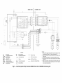
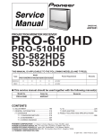
Heat Pump System Wiring Schematic
Terminal Block
Factory Wiring
....
Field Control Wiring
,......-.....
Field Power Wiring
-----
Accessory
40BNE018,024
or Optional Wiring
NOTES:
1. If any of the original wire furnished must be replaced, it must
be replaced with Type 90 ° C wire or its equivalent.
2. Wire in accordance with National Electrical Code (NEC) and
local codes.
3. Thermistor wiring cable 32 ft long provided with indoor unit.
4. Compressor and fan motors are protected by internal thermal
overloads.
5. Indoor unit shown with power source from outdoor unit.
Indoor unit may be wired to separate power source depending on service requirements.
Fan Coil with 38BNE018,024
Condensing
Unit
/_
,.'
INDOOR
iJ
UNIT
0UTD00R
riLl
Si
UNIT
P
/
D
..................
/w y_
2B
\
.................................
;4
','_C ?1,
Y '(_17
]
,,c 8o I
h- _i
C(}N
L/i!
?
i
ROLLER
F {EID
POWER
5UPP[
_o ou?oooR UN!T
I}{SCONNECi
9RN/YEL
BL t
Y
8f/N/yffL
BRN
iB
LEGEND
C
-CC
-COMPFC
-GND -IFM
-OFM -RVS
-SW
--
Contactor
Compressor Capacitor
Compressor
Fan Capacitor
Ground
Indoor-Fan Motor
Outdoor-Fan Motor
Reversing Valve Solenoid
Sweep Motor
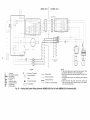
Fig. 14 i
TB
TH
---
Terminal Block
Thermistor/Thermostat
--
Terminal (Marked)
[_
Factory Wiring
Field Control Wiring
O
Splice
.....
Field PowerWiring
•
Terminal (Unmarked)
-----
Accessory or Optional Wiring
Terminal
Block
u
NOTES:
1. If any of the original wire furnished must be replaced, it must
be replaced with Type 90 ° C wire or its equivalent.
2. Wire in accordance with National Electrical Code (NEC) and
local codes.
3. Thermistor wiring cable 32 ft long provided with indoor unit.
4. Compressor and fan motors are protected by internal thermal
overloads.
5. Indoor unit shown with power source from outdoor unit.
Indoor unit may be wired to separate power source depending on service requirements.
Heat Pump System Wiring Schematic 40BNE030 Fan Coil with 38BNE030 Condensing
Unit
INDOOR UNIT
OUTDOOR UNIT
i_ i,J
/
?
}It}
BPL
it{}
CONrrToL b i77 NO
J8
r]
i4
RE
L
J
i
i
/
J9
8R
f) [ pl A _'
=<
I
i
I
i
I
i
I
|
FI{O
P(},,, }7 <_U:>PLY
1o o 7oook tFJ{
NSCON\ C
4
8f_S
TB
LEGEND
C
-- Contactor
CC
-- Compressor Capacitor
COMPCompressor
FC
-- Fan Capacitor
GND -- Ground
IFM
-- Indoor-Fan Motor
OFM -- Outdoor-Fan Motor
SW
-- Sweep Motor
TB
-- Terminal Block
Fig. 15-
TH
--
Thermistor/Thermostat
--
Factory Wiring
Terminal (Marked)
O
•
....
Field Control Wiring
,,.,,.,,,,.
Field Power Wiring
Splice
Terminal (Unmarked)
Accessory
[_
Cooling
or Optional Wiring
Terminal Block
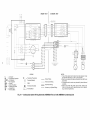
Only System Wiring Schematic
40BNB018,024
NOTES:
1. If any of the original wire furnished must be replaced, it must
be replaced with Type 90 ° C wire or its equivalent.
2. Wire in accordance with National Electrical Code (NEC) and
local codes.
3. Compressor and fan motors are protected by internal thermal
overloads.
4. Indoor unit shown with power source from outdoor unit.
Indoor unit may be wired to separate power source depending on service requirements.
Fan Coil with 38BNB018,024
Condensing
Unit
INDOOR
UNIT
OUTDOOR
UNIT
_2
--FIE
J
//
J7
O SbPJ
ONROL
_
T
RTNG
/" <
i
i
K
I
CONYR
i
RiD
_EO
i
_,HT
]-
BRN
T[
{L
\_
13
C
! wm
..... i
i
i
SEE NOT
4 ................/
L_
io
i
8LU
K] =
u
,,
iL i
CONIRO[i
_i
R
L_
,:
GR_/YEL
FIELD
o
B[(
mRI
POWER
SUPPl
OUTDO0_ /JN T
DISCO! NECT
RN/YIBR
B
LEGEND
C
-CC
-COMPFC
-GND -IFM
-OFM -SW
-TB
--
Contactor
Compressor Capacitor
Compressor
Fan Capacitor
Ground
Indoor-Fan Motor
Outdoor-Fan Motor
Sweep Motor
Terminal Block
TH
-- Thermistor/Thermostat
@
0
•
--
Factory Wiring
....
Field Control Wiring
,,,,,,,,,,,,
Field Power Wiring
Terminal (Marked)
Splice
Terminal (Unmarked)
Accessory
[_
Terminal Block
Fig. 16 -- Cooling Only System Wiring Schematic
or Optional Wiring
NOTES:
1. If any of the original wire furnished must be replaced, it must
be replaced with Type 90 ° C wire or its equivalent.
2. Wire in accordance with National Electrical Code (NEC) and
local codes.
3. Compressor and fan motors are protected by internal thermal
overloads.
4. Indoor unit shown with power source from outdoor unit.
Indoor unit may be wired to separate power source depending on service requirements.
40BNB030 Fan Coil with 38BNB030 Condensing
Unit
START-UP
System
40BNB, BNE Indoor
Checks
1. Conceal the tubing where possible.
2. Make sine that the diainage tube slopes downward
its entire length.
Ensure all tubing and connections
Fasten tubes to the outside wall.
5.
Seal the hole through which file cables and tubing pass.
6.
Connect the air conditioner
it on.
are properly insulated.
to the power source and turn
7.
Check all air conditioner
operating
Owner's Manual for operating details.
INDOOR UNIT
1. Do all the remote controller
To avoid the possibility of electric shock, before performing
any cleaning and maintenance operations, always turn off
power to the system by pressing the mode button on the
remote control until the display shows "OFE" and turn off
the sepal'ate disconnect switch located near the unit. If the
indoor unit is on a separate switch, be sure to turn this disconnect off as well.
_dong
3.
4.
modes.
Refer
to
Do not wash filter in
Do not expose filter
expose filter to direct
when air is extremely
buttons function properly?
2.
Do the display panel lights work properly?
3.
Does the air deflection
Do not attempt to clean or service components in control
box.
1. Are there unusual noises or vibrations
Is noise, di'ain water
disturb the neighbors?
water over 120 F (to avoid shrinkage).
to fire (to avoid fire &image). Do not
sunlight. Clean filter more frequently
dirty.
louver function properly?
4. Does the di'ainage work?
OUTDOOR UNIT
2.
Units
or airflow
3. Are there any gas leaks?
EXPLAIN
THE
FOLLOWING
CUSTOMER,
WITH
THE AID
MANUAL:
during operation?
To Clean
fiom the unit likely to
ITEMS
OF THE
TO
THE
OWNER'S
How to set the air deflection
4.
5.
Explain cme and maintenance.
Present the Owner's Manual and installation
to the customer.
Unit Front
Panel --
If
the
To Clean Indoor
Coil--To
clean file coil, remove
indoor unit front panel and vacuum the coil fins, using care not
to bend or dalnage fins.
1. How to turn the air conditioner on and off; selecting cooling, heating and other operating modes; setting a desired
temperatme;
setting the timer to automatically
start and
stop air conditioner operation; and the other features of
the remote controller and display panel.
2. How to remove and clean the air filter
3.
the Indoor
fi'ont panel of the unit becomes dirty or smudged, wipe the outside of the panel with a soil diy cloth. Use a mild liquid detergent and wipe off cmelhlly with a @ cloth.
LUBRICATION
the outdoor-fan
oiling.
-- Tile indoor-fan, automatic air sweep, and
motol_ _u'e factory lubricated and require no
Air Filters for 38BNB,BNE
40BNB, BNE Indoor Units
Outdoor
Units and
louvel:
instructions
Operating your system with dirty air filters may &image
the indoor unit and, in addition, can cause reduced performance, intermittent system operation, fi_st build up on the
indoor coil, and blown fuses. Inspect and clean or replace
the air filters monthly.
CARE AND MAINTENANCE
The following may be perforlned by the equipment owner
38BNB,BNE
Outdoor
TO REMOVE AIR FILTERS -- Remove filters by pulling
them straight out.
TO CLEAN OR REPLACE FILTERS -- Filters can be vacuumed or washed in wtum watec Shake filter to remove any
excess watel: and replace by sliding filter behind grille until
filter snaps in place. If the filter has begun to break down or is
torn, replace it. Replacement
filters are available through a
loc_d de_del:
Units
Before performing recommended maintenance, be sure unit
main power switch is turned off. Failure to do so may result
in electric shock or injury from rotating fan blade.
CLEANING
COILS--Coil
should be washed
out with
water or blown out with compressed all: Clean coil annually or
as required by location and outdoor air conditions. Inspect coil
monthly and clean as required. Fins are not continuous through
coil sections. Dill and debris may pass through first section,
become trapped between the row of fins and restrict outdoor
unit airflow. Use a flashlight to determine if dirt or debris has
collected between coil sections.
SERVICE
The following
technician.
Clean Condensate
Clean coil as follows:
Using a gmden hose or other suitable equipment, flush
coil from the outside to remove dirt. Be sure to flush _dl
dirt and debris from di'ain holes in base of unit. Fan
motors are waterproof.
by a qualified
Drains--Clean
service
all drains and
drain pans at the start of each cooling
by pouring water into the drain.
season. Check the flow
Clean
The drain pan
by a qualified service
or
Replace
should only be cleaned
technician.
1. Turn off unit power and install lockout tag.
2.
should be performed
Drain
Pan --
or replaced
1. Place a plastic sheet on the floor to catch any water that
may spill from the drain pan.
2. Remove the intake grille and distribution assembly.
3. Remove the condensate water in the drain pan by letting
water drain into a 3-gallon bucket.
12
TROUBLESHOOTING
(Tables
Be sure to check for broken
before troubleshooting
systeln.
wires
6-8, and Fig. 17)
or loose cable
lugs
Table 6 -- Service Indicators
LAMP STATUS
INDICATION
Flashing*
CORRECTION
ACTION
Dirty filter
Clean the filter.
1 Flash
Faulty TH1 Sensor
Check the TH1 thermistor for correct resistance.
Check for proper connection.
Replace thermistor if necessary.
2 Flashes
Faulty TH2 Sensor
Check the TH2 thermistor for correct resistance.
Check for proper connection.
Replace thermistor if necessary.
3 Flashes
Low Pressure
Check system pressures.
Check refrigerant charge.
Check thermistors (TH1 and TH2) for correct resistance.
4 Flashes
High Pressure
Check system pressures.
Check refrigerant charge.
Check thermistors (TH1 and TH2) for correct resistance.
5 Flashes
Low Voltage
Check operating voltage.
Check electrical connections.
6 Flashes
High Voltage
Check operating voltage.
Check electrical connections.
*The Filter Indicator Lamp will flash repeatedly when the filter needs cleaning. The remainder of
the table refers to the Service Indicator Light. Both lights are found underneath the grille cover.
For more information, refer to the Owner's Manual.
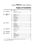
OPERATION
LED.
INDICATES ERROR
POWER LED.
OFF WHEN SYSTEM
IS
OPERATING
AND FLASHES
WHEN SYSTEM IS IN ERROR.
(DOES
NOT INDICATE
ERROR CODE)
CLEAN FILTER INDICATOR.
FLASHES AFTER 2500 HOURS
OF OPERATION
Fig. 17 -- Indicator Lights
13
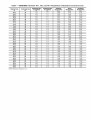
Table7 -- 40BNB/BNE Thermistor TH-1, TH-2, and TH-3 Temperature to Resistance Conversion
TEMPEATURE
TEMPERATURE
TEMPERATURE
TOLERANCE
TEMPERATURE
TOLERANCE
MINIMUM
RESISTANCE
MEAN
RESISTANCE
MAXIMUM
RESISTANCE
(F)
(c)
(F)
(C)
(K_)
(K_)
(K_)
-4.0
-20
_+2.0
_+1.1
30.89
32.44
34.05
-2.2
-19
•+2.0
_+1.1
29.46
30.93
32.45
-0.4
1.4
-18
-17
•+2.0
_+1.1
28.12
29.51
30.94
•+2.0
_+1.1
26.84
28.16
29.51
3.2
-16
•+2.0
_+1.1
25.64
26.88
28.15
5.0
-15
•+2.0
_+1.1
24.49
25.66
26.87
6.8
-14
•+2.0
_+1.1
23.40
24.52
25.66
8.6
-13
•+2.0
_+1.1
22,38
23.43
24.50
10.4
-12
•+2.0
_+1.1
21.40
22,39
23.41
12.2
-11
•+2.0
_+1.1
20.47
21.41
22.38
14.0
-10
•+1.8
_+1.0
19.59
20.48
21.40
15.8
-g
•+1.8
_+1.0
18.74
19.59
20.45
17.6
19.4
--8
-7
•+1.8
_+1.0
17.94
18.74
19.56
•+1.8
_+1.0
17.17
17.93
18.71
21.2
-6
•+1.8
_+1.0
16.44
17.16
17.90
23.0
-6
•+1.8
_+1.0
15.75
16.43
17.13
24.8
-4
•+1.8
_+1.0
15.10
15.74
16.40
26.6
-3
•+1.8
_+1.0
14.47
15.08
15.71
28.4
-2
•+1.8
_+1.0
13.87
14.46
15.05
30.2
-1
•+1.8
_+1.0
13.31
13.86
14.42
32.0
0
•+1.8
_+1.0
12,77
13.29
13.83
33.8
1
•+1.8
_+1.0
12.25
12.74
13.25
35.6
2
•+1.8
_+1.0
11.75
12.22
12.70
37.4
3
•+1.8
_+1.0
11.28
11.73
12.18
39.2
4
•+1.8
_+1.0
10.83
11.25
11.68
41.0
5
•+1.8
_+1.0
10.40
10.80
11.21
42.8
6
•+1.8
_+1.0
9.986
10.370
10.76
44.6
46.4
7
8
•+1.8
_+1.0
9.595
9.960
10.33
•+1.8
_+1.0
9.222
9.569
9.921
48.2
0
•+1.8
_+1.0
8.866
9.196
9.530
50.0
10
•+1.8
_+1.0
8.526
8.840
9.157
51.8
11
•+1.8
_+1.0
8.197
8.496
8.797
53.6
12
•+1.8
_+1.0
7.883
8.167
8.453
55.4
57.2
13
14
•+1.6
_+0.9
7.583
7.853
8.125
•+1.6
_+0.9
7.296
7.553
7.812
59.0
15
•+1.6
_+0.9
7.022
7.267
7.513
60.8
16
•+1.6
_+0.9
6.761
6.993
7.227
62.6
17
•+1.6
_+0.9
6.510
6.731
6.954
64.4
66.2
18
19
•+1.6
_+0.9
6.271
6.481
6.693
•+1.6
_+0.9
6.042
6.242
6.444
68.0
20
•+1.6
_+0.9
5.822
6.013
6.208
69.8
21
•+1.6
_+0.9
5.611
5.793
5.978
71.6
22
•+1.6
_+0.9
5.408
5.581
5.755
73.4
23
•+1.6
_+0.9
5.214
5.379
5.544
75.2
24
•+1.6
_+0.9
5.028
5.185
5.343
77.0
25
•+1.6
_+0.9
4.850
5.000
5.150
78.8
26
•+1.6
_+0.9
4.675
4.821
4.968
80.6
27
•+1.6
_+0.9
4.508
4.650
4.793
82.4
84.2
28
29
•+1.6
_+0.9
4.347
4.486
4.626
•+1.8
_+1.0
4.193
4.329
4.466
86.0
30
•+1.8
_+1.0
4.046
4.179
4.312
87.8
31
•+1.8
_+1.0
3.904
4.033
4.163
89.6
91.4
32
33
•+1.8
_+1.0
3.767
3.894
4.020
•+1.8
_+1.0
3.637
3.760
3.884
93.2
34
•+1.8
_+1.0
3.511
3.631
3.752
95.0
35
•+1.8
_+1.0
3.391
3.508
3.626
96.8
36
•+2.0
_+1.1
3.275
3.390
3.505
98.6
37
•+2.0
_+1.1
3.164
3.276
3.389
NOTE: Resistance
tolerance _+3%.
14
Table7 -- 40BNB/BNE Thermistor TH-1, TH-2, and TH-3 Temperature to Resistance Conversion
TEMPEATURE
TEMPERATURE
TEMPERATURE
TOLERANCE
(F)
_+2.0
TEMPERATURE
TOLERANCE
(C)
_+1.1
(cont)
MINIMUM
RESISTANCE
(K£_)
3.058
MEAN
RESISTANCE
(K£_)
3.167
MAXIMUM
RESISTANCE
(K_)
3.277
(F)
100.4
(C)
38
102.2
39
_+2.0
_+1.1
2,956
3.062
3.169
104.0
105.8
40
41
_+2.0
_+2.0
_+1.1
_+1.1
2,857
2,762
2.961
2.864
3.066
2,966
107.6
42
_+2.0
_+1.1
2,671
2.770
2,870
109.4
43
_+2.2
_+1.2
2,583
2.679
2,777
111.2
44
_+2.2
_+1.2
2,498
2.593
2,688
113.0
45
_+2.2
_+1.2
2,417
2.509
2,602
114.8
46
_+2.2
_+1.2
2,339
2.429
2,520
116.6
47
_+2.2
_+1.2
2,264
2.352
2,441
118.4
48
_+2.3
_+1.3
2,192
2.227
2,364
120.2
49
_+2.3
_+1.3
2,122
2.206
2,291
122.0
123.8
50
51
_+2.3
_+2.3
_+1.3
_+1.3
2,055
1.990
2.137
2.070
2,220
2,151
125.6
52
_+2.3
_+1.3
1.928
2.006
2,085
127.4
53
_+2.3
_+1.3
1.867
1.943
2,021
129.2
54
_+2.3
_+1.3
1.809
1.883
1.959
131.0
55
_+2.5
_+1.4
1.753
1.826
1.900
132.8
56
_+2.5
_+1.4
1.699
1.770
1.842
134.6
57
_+2.5
_+1.4
1.647
1.717
1.787
136.4
58
_+2.5
_+1.4
1.597
1.665
1.734
138.2
59
_+2.5
_+1.4
1.549
1.615
1.683
140.0
60
_+2.5
_+1.4
1.503
1.567
1.633
141.8
61
_+2.7
_+1.5
1.458
1.521
1.585
143.6
62
_+2.7
_+1.5
1.414
1.476
1.539
145.4
63
_+2.7
_+1.5
1.372
1.432
1.494
147.2
64
_+2.7
_+1.5
1.332
1.391
1.451
149.0
150.8
65
66
_+2.7
_+2.9
_+1.5
_+1.6
1.293
1.255
1.350
1.311
1.409
1.369
152.6
67
_+2.9
_+1.6
1.219
1.274
1.330
154.4
68
_+2.9
_+1.6
1.184
1.237
1.292
156.2
69
_+2.9
_+1.6
1.150
1.202
1.256
158.0
70
_+2.9
_+1.6
1.117
1.168
1.221
NOTE: Resistance
tolerance _+3%.
Table 8 -- General System Troubleshooting
SYMPTOM
Unit Fails to Start.
PROBABLE CAUSE
CORRECTIVE
Only Indoor Fan Motor and
Outdoor Fan Motor are Working.
No Cooling and/or Heating Takes
Place.
No Air Supply at Indoor Unit
(Compressor Operates).
Check for proper connection of power at disconnect.
Fuse blown (POWER LED Off).
Reset circuit breaker or replace line fuse.
Press ON/SEND button on remote control.
Make sure that nothing is blocking the remote control
transmission to the unit.
The selected mode is Fan Only, or Cool when
heating is desired.
Check if the remote control is in the desired mode. If
not, select the correct mode (refer to User manual).
Also note that every 15 minutes (maximum) the com)ressor will be switched minimally on for 3 minutes.
Temperature
Cool mode).
Observe the temperature setting on the remote control.
Also note that each 15 minutes (maximum), the com)ressor will be switched on minimally for 3 minutes.
is set to a value which is too high (in
Overload safety device on compressor
due to high temperature.
is cut out
Switch off power and try again after one hour.
Compressor
run capacitor is burnt.
Replace compressor
Compressor
winding shorted.
Replace compressor.
run capacitor.
Indoor fan motor is blocked or turns slowly.
1. Check voltage. Repair wiring if necessary.
2. Check indoor fan wheel if tight on motor shaft.
Tighten if necessary.
Indoor fan motor capacitor is burnt.
Replace indoor fan motor capacitor.
Indoor fan motor winding is burnt.
Replace indoor fan motor.
In Heat mode: Delayed start for indoor fan motor.
Normal software delay (maximum of 20 sec).
Clean filters.
Clogged air filters.
Low Capacity.
ACTION
Power supply to unit not connected (POWER LED
Off).
ON/SEND button has not been pressed.
Indoor unit does not receive transmitted
commands.
Only Indoor Fan Works when
Cooling or Heating is Desired.
NOTE: Indoor fan runs
continuously in cooling mode.
Guide
Lack of refrigerant.
tor coil.
Ice formation on the evapora-
Clogged air filters.
Unit must be charged (according
after localizing the gas leak.
Clean filters.
to the nameplate)
In Heat Mode, Only Compressor
Runs. Outdoor and Indoor Fan
Motors are Stopped.
A/C operating in defrost cycle.
Wait 10 minutes (maximum)
normal operation.
Water Accumulates and
Overflows from Evaporator
Drain Pan.
Drain pan pipe or hose is clogged or the spout of
drain pan is clogged,
Disassemble plastic drain pipe from spout of evaporator drain pan. Flush with clean water.
Unit Does Not Operate
Mode.
The unit is in the Auto. (emergency)
Push button once to cancel Auto. (emergency)
in Desired
The Unit Receives Interference
from Other Remote Control or
the Remote Control Interferes
with Other Instruments.
mode.
until the unit resumes
mode.
Faulty remote control settings.
1. If remote control symbols respond to the commands
correctly, check the unit ID Code (Standard or Alternative). Refer to "Changing Unit ID Code" in the
Owner's Guide and Remote Control DIP switch 3
setting in the Owner's Manual.
2. If Cool commands are OK, but Heat symbol is
skipped on LCD, refer to Remote Control DIP switch
7 setting in the Owner's Manual.
3. Replace remote control.
Remote control low battery.
Common Infrared Code.
Replace remote control batteries.
Modify the Remote Control IR transmission code.
Refer to "Changing Unit ID Code" and to Remote
Control DIP switch 3 setting in the Owner's Manual.
Copyright 2005 Carrier Corporation
Manufacturer reserves the right to discontinue, or change at any time, specifications
PC 111
Catalog No. 533-80122
Printed in U.S.A.
or designs without notice and without incurring obligations.
Form 38B/40B-4SI
Pg 16
5-05
Replaces:
38B/40B-1SI,
38B/40B-2Sl