1
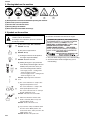
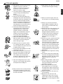
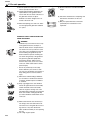
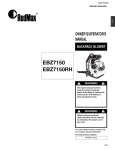
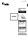
GZ4500
848-C5A-93A3 (909)
U
S
OWNER'S/OPERATOR'S
MANUAL
CHAINSAW
GZ4500
WARNING
The engine exhaust from this
product contains chemicals
known to the State of California to
cause cancer, birth defects or
other reproductive harm.
WARNING
Before using our products,
please read this manual carefully
to understand the proper use of
your unit.
APPLICABLE SERIAL NUMBERS :
703782 and up
US-1
GZ4500
SAFETY FIRST
Instructions contained in warnings within this
manual marked with a
symbol concern critical
points which must be taken into consideration to
prevent possible serious bodily injury, and for this
reason you are requested to read all such
instructions carefully and follow them without fail.
■ WARNINGS IN THE MANUAL
WARNING
This mark indicates instructions which must be
followed in order to prevent accidents which could lead
to serious bodily injury or death.
IMPORTANT
This mark indicates instructions which must be
followed, or it leads to mechanical failure, breakdown,
or damage.
NOTE
This mark indicates hints or directions useful in the use
of the product.
Contents
1.
2.
3.
4.
5.
6.
7.
8.
9.
10.
11.
12.
13.
14.
US-2
Parts location …………………………………………………3
Specifications …………………………………………………3
Warning labels on the machine ………………………………4
Symbols on the machine ……………………………………4
For safe operation ……………………………………………5
Installing guide bar and saw chain …………………………7
Fuel and chain oil………………………………………………8
Operation ……………………………………………………10
Sawing…………………………………………………………13
Maintenance …………………………………………………15
Maintenance of saw chain and guide Bar …………………17
Storage ………………………………………………………18
Disposal ………………………………………………………18
Troubleshooting guide ………………………………………18
GZ4500
1. Parts location
U
S
1.
2.
3.
4.
5.
6.
7.
8.
9.
10.
11.
12.
13.
Front guard
Starter knob
Air cleaner cover
Choke knob
Throttle interlock
Right handle
Throttle lever
Engine switch
Fuel tank
Oil tank
Left handle
Saw chain
Guide Bar
2. Specifications
■ GZ4500
Power unit :
Displacement ·············································································································· 2.69(44.0) cu-in(cm3)
Fuel ······································································································· Mixture(Gasoline 50 : 2-cycle oil 1)
(when using RedMax genuine oil)
Fuel tank capacity ··········································································································· 10.4(0.31) fl.oz( )
Chain oil ·················································································································· Motor oil SAE #10W-30
Oil tank capacity ············································································································· 7.10(0.21) fl.oz( )
Carburetor ····································································································· Diaphragm type (Walbro WT)
lgnition system ····················································································································· Pointless (CDI)
Spark plug ······························································································································ NGK CMR7H
Oil feeding system ·············································································································· Automatic pump
Power ······························································································································1.9/9,500 (kw/min-1)
Max speed ································································································································13,000 (min-1)
Idle speed ···································································································································2,700 (min-1)
Sprocket : Pitch – No. of teeth ··················································································· .325in(8.26mm) – 7T
Dimensions : L – W – H ··································································· 14.8(370)x9.4(235)x10.8(270) in(mm)
Dry weight : Power unit only ······························································································ 9.6(4.35) lbs(kg)
Cutting attachment :
Guide bar : Type – Size ··································································· Sprocket nose – 16(40), 18(45) in(cm)
Saw chain : Type – Pitch – Gauge ·································· Oregon 95VP – .325(8.26) – 0.050(1.27) in(mm)
Specifications are subject to change without notice.
US-3
GZ4500
3. Warning labels on the machine
(1) Read operator's instruction book before operating this machine.
(2) Wear head, eye and ear protection.
(3) Use the chain saw with two hands.
(4) Warning! Danger of kickback.
(5) Read, understand and follow all warnings.
4. Symbols on the machine
For safe operation and maintenance, symbols are
carved in relief on the machine.
According to these indications, please be careful not
to make any mistake.
(a) The port to refuel “MIX GASOLINE”
Position: Fuel cap
(b) The port to top up chain oil
Position: Oil cap
(c) Setting the switch to the “O” position,
the engine stops immediately.
Position: Rear-left of the unit
(d) Starting the engine. If you pull out the
choke knob (at the back-right of the rear
handle) to the point of the arrow, you
can set the starting mode as follows:
• First-stage position – starting mode
when the engine is warm.
• Second-stage position – starting mode
when the engine is cold.
Position: Upper-right of the aircleaner
cover
(e) The screw under the “H” stamp is The
High-speed adjustment screw.
The screw under the “L” stamp is The
Slow-speed adjustment screw.
The screw at the left of the “T” stamp is
the Idle adjustment screw.
Position: Left side of the rear handle
(f) Shows the directions that the chain
brake is released (white arrow) and
activated (black arrow).
Position: Front of the chain cover
(g) If you turn the rod by screwdriver follow
the arrow to the "MAX" position, the
chain oil flow more, and if you turn to the
"MIN" position, less.
Position: Bottom of the power unit
US-4
■ EMISSION CONTROL
An emission control label is located on the engine.
EMISSION CONTROL INFORMATION
THIS ENGINE MEETS U.S. EPA AND CALIFORNIA
EXH/EVP REGS FOR 2009*1 S.O.R.E.
ENGINE FAMILY : 9HQZS.0444BJ*2 DISPL.: 44cc
EMISSION CONTROL SYSTEM : EXH;EM
COMPLIANCE PERIOD : 125 HOURS
REFER TO OPERATOR'S MANUAL FOR MAINTENANCE, SPECIFICATIONS AND ADJUSTMENTS.
MANUFACTURED:
USE JASO FD OR ISO L-EGD GRADE 50:1 OIL
*1: The year will be changed every year of manufacturing.
*2: The initial number will be changed every year of
manufacturing.
GZ4500
5. For safe operation
1. Never operate a chain saw when you are
fatigued, ill, or upset, or under the
influence of medication that may make
you drowsy, or if you are under the
influence of alcohol or drugs.
2. Use safety footwear, snug fitting clothing
and eye, hearing and head protection
devices.
Use the vibration-proof glove.
3. Keep the saw chain sharp and the saw,
including the AV system, well maintained.
A dull chain will increase cutting time, and
pressing a dull chain through wood will
increase the vibrations transmitted to your
hands. A saw with loose components or
with damaged or worn AV buffers will also
tend to have higher vibration levels.
4. All the above mentioned precautions do
not guarantee that you will not sustain
whitefinger disease or carpal tunnel
syndrome. Therefore, continual and
regular users should monitor closely the
condition of their hands and fingers.
If any of the above symptoms appear,
seek medical advice immediately.
5. Always use caution when handling fuel.
Wipe up all spills and then move the chain
saw at least 3 m from the fueling point
before starting the engine.
6. Eliminate all sources of sparks or flame
(i.e. smoking, open flames, or work that
can cause sparks) in the areas where fuel
is mixed, poured, or stored.
7. Do not smoke while handling fuel or while
operating the chain saw.
8. Do not allow other persons to be near the
chain saw when starting or cutting. Keep
bystanders and animals out of the work
area. Children, pets and bystanders
should be a minimum of 10 m away when
you start or operate the chain saw.
9. Never start cutting until you have a clear
work area, secure footing, and a planned
retreat path from the falling tree.
10. Always hold the chain saw firmly with both
hands when the engine is running. Use a
firm grip with thumb and fingers encircling
the chain saw handles.
11. Keep all parts of your body away from the
saw chain when the engine is running.
U
S
12. Before you start the engine, make sure
the saw chain is not contacting anything.
13. Always carry the chain saw with the
engine stopped, the guide bar and saw
chain to the rear, and the muffler away
from your body.
14. Always inspect the chain saw before each
use for worn, Ioose, or damaged parts.
Never operate a chain saw that is
damaged, improperly adjusted, or is not
completely and securely assembled. Be
sure that the saw chain stops moving
when the throttle control trigger is
released.
15. All chain saw service, other than the items
listed in the Owner’s Manual, should be
performed by competent chain saw
service personnel. (E.g., if improper tools
are used to remove the flywheel, or if an
improper tool is used to hold the flywheel
in order to remove the clutch, structural
damage to the flywheel could occur which
could subsequently cause the flywheel to
disintegrate.)
16. Always shut off the engine before setting
it down.
17. Use extreme caution when cutting small
size brush and saplings because slender
material may catch the saw chain and be
whipped toward you or pull you off
balance.
18. When cutting a limb that is under tension,
be alert for spring- back so that you will
not be struck when the tension in the
wood fibers is released.
19. Never cut in high wind, bad weather,
when visibility is poor or in very high or
low temperatures. Always check the tree
for dead branches which could fall during
the felling operation.
20. Keep the handles dry, clean and free of
oil or fuel mixture.
21. Operate the chain saw only in well
ventilated areas. Never start or run the
engine inside a closed room or building.
Exhaust fumes contain dangerous carbon
monoxide.
US-5
GZ4500
5. For safe operation
22. Do not operate the chain saw in a tree
unless specially trained to do so.
23. Guard against kickback. Kickback is the
upward motion of the guide bar which
occurs when the saw chain at the nose of
the guide bar contacts an object.
Kickback can lead to dangerous loss of
control of the chain saw.
24. When transporting your chain saw, make
sure the appropriate guide bar scabbard
is in place.
KICKBACK SAFETY PRECAUTIONS FOR
CHAIN SAW USERS
WARNING
Kickback may occur when the nose or tip
of the guide bar touches an object, or
when the wood closes in and pinches the
saw chain in the cut. Tip contact in some
cases may cause a lightning fast reverse
reaction,kicking the guide bar up and
back towards the operator. Pinching the
saw chain along the top of the guide bar
may push the guide bar rapidly back
towards the operator. Either of these
reactions may cause you to Iose control
of the saw, which could result in serious
personal injury.
• Do not rely exclusively on the safety
devices built into your saw. As a chain
saw user you should take several steps to
keep cutting jobs free from accident or
injury.
(1) With a basic understanding of kickback
you can reduce or eliminate the element
of surprise. Sudden surprise contributes
to accidents.
(2) Keep a good grip on the saw with both
hands, the right hand on the rear handle,
and the left hand on the front handle,
when the engine is running. Use a firm
grip with thumbs and fingers encircling the
chain saw handles. A firm grip will help
you reduce kickback and maintain control
of the saw.
•
(3) Make certain that the area in which you
are cutting is free from obstructions. Do
not let the nose of the guide bar contact a
log, branch, or any other obstruction
which could be hit while you are operating
the saw.
(4) Cut at high engine speeds.
US-6
(5) Do not overreach or cut above shoulder
height.
(6) Follow the manufacturer’s sharpening and
maintenance instructions for the saw
chain.
(7) Only use replacement bars and chains
specified by the manufacturer or the
equivalent.
GZ4500
6. Installing guide bar and saw chain
F1
■ A standard saw unit package
contains the items as illustrated.
(F1)
(1) Power unit
(2) Guide bar
(3) Saw chain
(4) Plug wrench
(5) Screwdriver for carburetor
adjustment
(4) Tensioner screw
(5) Lift up
NOTE
A new chain will expand its length in the
beginning of use. Check and readjust the
tension frequently as a loose chain can
easily derail or cause rapid wear of itseif
and the guide bar.
Open the box and install the guide bar
and the saw chain on the power unit as
follows:
WARNING
The saw chain has very sharp edges.
Use thick protective gloves for safety.
F2
1. Pull the guard towards the front handle
to check that the chain brake is not
engaged.
2. Loosen the nuts and remove the chain
cover.
3. Gear the chain to the sprocket and,
while fitting the saw chain around the
guide bar, mount the guide bar to the
power unit. Adjust the position of the
chain tensioner. (F2)
(1) Tensioner nut
(2) Chain cover
F3
NOTE
Pay attention to the correct direction of
the saw chain. (F3)
(1) Moving Direction
F4
4. Fit the chain cover to the power unit
and fasten the nuts to finger tightness.
5. While holding up the tip of the bar,
adjust the chain tension by turning the
tensioner screw until the tie straps just
touch the bottom side of the bar rail.
(F4)
6. Tighten the nuts securely with the bar
tip held up (12~15 N·m). Then check
the chain for smooth rotation and
proper tension while moving it by hand.
If necessary, readjust with the chain
cover loose.
7. Tighten the tensioner screw.
(2) Loosen
(3) Tighten
US-7
U
S
GZ4500
7. Fuel and Chain Oil
■ FUEL
lines or fuel tank of the engine.
WARNING
• Gasoline is very flammable. Avoid smoking or bringing any
flame or sparks near fuel. Make sure to stop the engine and
allow it cool before refueling the unit. Select outdoor bare
ground for fueling and move at least 10 ft (3 m) away from
the fueling point before starting the engine.
■ GASOLINE REQUIREMENTS
• All 2-Stroke RedMax Products are powered by RedMax
Professional-Commercial Duty, Hi-Performance, Hi-RPM, Air
Cooled 2-Stroke engines.
RedMax – Hi-Performance 2-stroke engines produce higher HP
outputs as compared to standard Home Owner Duty or Light
Commercial Duty production engines offered by most
manufacturers.
• Exhaust emission are controlled by the fundamental engine
parameters and components (eq., carburation, ignition timing
and port timing) without addition of any major hardware or the
introduction of an inert material during combustion.
• The RedMax Engines are registered and certified with CARB
(California Air Resources Board) and EPA (Environmental
Protection Agency) to operate on CLEAN Mid-grade 89 octane
or Premium, unleaded (lead-free) gasoline and RedMax AirCooled "Max Life", Synthetic blend Premium two-stroke engine
oil mixed at 50:1 ratio.
• Unleaded gasoline is recommended to reduce the
contamination of the air for the sake of your health and the
environment.
• This Hi-Performance Air Cooled 2-stroke Engine requires the
use of Minimum 89 Octane [ R+M ] (Mid grade or Premium)
2
clean gasoline. Gasoline may contain maximum of 10% Ethanol
(grain alcohol) or up to 15% MTBE (Methyl tertiary-butyl ether).
Gasoline containing Methanol (Wood Alcohol) is NOT
approved.
NOTE
• Failures caused by operating engines on gasoline with octane
rating lower than 89 are not covered by the RedMax TwoStroke engine warranty.
WARNING
• Alternative Fuels (Not Gasoline)
Alternative fuels, such as E-15 (15% ethanol), E-20 (20%
ethanol), E-85 (85% ethanol) are NOT classified as gasoline
and are NOT approved for use in RedMax 2-stroke gasoline
engines. Use of alternative fuels will cause major engine
performance and durability problems such as: improper
clutch engagements, overheating, vapor lock, power loss,
lubrication deficiency, deterioration of fuel lines, gaskets
and internal carburetor components, etc... Alternative fuels
cause high moisture absorption into the fuel/oil mixture
leading to oil and fuel separation.
■ OIL REQUIREMENTS
• Use only RedMax "Max Life", Synthetic blend Premium AirCooled two-stroke engine oil or oil certified to ISO-L-EGD
(ISO/CD1378) standard AND one that is JASO-FD registered.
RedMax Air-Cooled "Max Life", Synthetic blend Premium two
stroke engine oil and ISO-L-EGD (ISO/CD1378) AND JASO-FD
oils are fully compatible with gasoline's containing 10% Ethanol.
RedMax Air-Cooled "Max Life", Synthetic blend Premium two
stroke engine oil and ISO-L-EGD (ISO/CD1378) AND JASO-FD
oils are Universal and should be mixed at 50:1 ratio for all 2
stroke air cooled engines sold in the past regardless of mixing
ratios specified in those manuals.
• If the oil is registered with JASO, the JASO Logo with FD and
registration number will be displayed on the container. The
highest JASO rating is "FD", which equals the ISO-L-EGD
rating. Lower ratings are "FC", "FB", and "FA".
NOTE
• IF octane rating of the Mid Grade gasoline in your area is lower
than 89 Octane use Premium Unleaded Gasoline. The majority
of all 2-stroke engine manufacturers in the USA and Canada
recommend using gasoline with 89 Octane or higher.
WARNING
• Gasoline with an octane rating lower than 89 will greatly
increase the engines operating temperature. Low octane
gasoline will cause detonation (knock) resulting in piston
seizures and major internal engine components damage.
• Poor quality gasolines or oils may damage sealing rings, fuel
US-8
• Engine problems due to inadequate lubrication caused by
failure to use ISO-L-EGD certified and JASO FD registered oil
such as "MaxLife", RedMax Synthetic blend Premium 2-stroke
oil WILL VOID THE REDMAX TWO-STROKE ENGINE
WARRANTY.
WARNING
• Do not use NMMA (National Marine Manufacturers
Association), BIA (Boating Industry Association), and TCW (two
cycle water cooled) oils designed for MoPeds or Outboard,
water cooled Marine Engines. Do not use API (American
Petroleum Institute), TC (Two Cycle) labeled oils. The API-TC
GZ4500
7. Fuel and Chain Oil
test standard has been discontinued by API in 1995 and it no
longer exists.
IMPORTANT
• Gasoline/Oil mixture Storage Recommendations
Store your gasoline or gasoline/oil mixture in a cool dry area in
a tightly sealed approved container to limit the entry of moisture
and additional air (oxygen). Moisture and air cause the
development of varnish and gum, making the fuel stale. Stored
gasoline and gasoline/oil mixture ages and loses its octane
rating and volatility. Do not mix more gasoline/oil than you
intend to use in 30 days, and 60 days when fuel stabilizer is
added. RedMax Air-Cooled "Max Life" Synthetic blend
Premium two-stroke engine oil "Contains fuel stabilizer" and
will automatically extend your gasoline/oil mixture life up to 60
days.
■ HOW TO MIX FUEL
RECOMMENDED MIXING RATIO
GASOLINE 50 : OIL 1
(when using RedMax Air-Cooled "Max
Life")
50:1 MIXING CHART
WARNING
1. Select flat and bare ground for fueling.
2. Move at least 10 feet (3 meters) away from the fueling point
before starting the engine.
3. Stop the engine before refueling the unit. At that time, be
sure to sufficiently agitate the mixed gasoline in the
container.
■ FOR YOUR ENGINE LIFE, AVOID
1. FUEL WITH NO OIL (RAW GASOLINE) – It will cause severe
damage to the internal engine parts very quickly.
2. GASOHOL – It can cause deterioration of rubber and/or plastic
parts and disruption of engine lubrication.
3. OIL FOR 4-CYCLE ENGINE USE – It can cause spark plug
fouling, exhaust port blocking, or piston ring seizure.
4. Mixed fuels which have been left unused for a period of
one month or more may clog the carburetor and result in the
engine failing to operate properly.
5. In the case of storing the product for a long period of time,
clean the fuel tank after rendering it empty. Next, Start the
engine and run the carburetor dry residual fuel.
6. In the case of scrapping the used mixed oil container, scrap it
only at an authorized depository site.
NOTE
GASOLINE
gal.
1
2
3
4
5
2-CYCLE OIL
fl.oz
2.6
5.2
7.8
10.4
13
GASOLINE
liter
1
2
3
4
5
2-CYCLE OIL
ml
20
40
60
80
100
WARNING
• Pay attention to agitation.
1. Measure out the quantities of gasoline and oil to be mixed.
2. Put some of the gasoline into a clean, approved fuel container.
3. Pour in all of the oil and agitate well for 10seconds.
4. Pour in the rest of gasoline and agitate again for at least one
minute. As some oils may be difficult to agitate depending on oil
ingredients, sufficient agitation is necessary. Be careful that, if
the agitation is insufficient, there is an increased danger of early
piston seizure due to abnormally lean mixture.
5. Place a clear indication on the outside of the container to avoid
mixing up with gasoline or other containers that dont contain oil.
6. Indicate the contents on outside of container for easy
identification.
• As for details of quality assurance, read the description in the
section Limited Warranty carefully. Moreover, normal wear and
change in product with no functional influence are not covered
by the warranty. Also, be careful that, if the usage in the
instruction manual is not observed as to the mixed gasoline,
type of oil or fuel to be used. described therein, it may not be
covered by the warranty.
■ CHAIN OIL
Use motor oil SAE #10W-30 all year round or SAE #30 ~ #40 in
summer and SAE #20 in winter.
NOTE
Do not use wasted or regenerated oil that can cause damage to
the oil pump.
■ FUELING THE UNIT
1. Untwist and remove the fuel cap. Rest the cap on a clean
surface.
2. Put fuel into the fuel tank to 80% of the full capacity.
3. Fasten the fuel cap securely and wipe up any fuel spillage
around the unit.
US-9
U
S
GZ4500
8. Operation
WARNING
F11
It is very dangerous to run a chainsaw
that mounts broken parts or lacks any
parts.
Before starting engine, make sure that
all the parts including bar and chain
are installed properly.
F7
4. While holding the saw unit securely on
the ground, pull the starter rope
vigorously. (F11)
WARNING
Do not start the engine while the chain
saw hangs in one hand. The saw chain
may touch your body. This in very
dangerous.
■ STARTING THE ENGINE
1. Fill fuel and chain oil tanks
respectively, and tighten the caps
securely. (F7)
5. When engine has ignited, first push in
the choke knob to the first-stage
position and then pull the starter again
to start the engine.
6. Allow the engine to warm up with the
throttle lever pulled slightly.
WARNING
2. Set the switch to “I” position. (F8)
F8
Keep clear of the saw chain as it will
start rotatIng upon starting of engine.
(1) Chain oil
(2) Fuel
(3) Switch
(4) Throttle lever
(5) Throttle interlock
■ CHECKING THE OIL SUPPLY
WARNING
Make sure to set up the bar and the
chain when checking the oil supply.
If not, the rotating parts may be
exposed. It is very dangerous.
F9
F12
After starting the engine, run the chain at
medium speed and see if chain oil is
scattered off as shown in the figure. (F12)
F10
3. Pull out the choke knob to the secondstage position. The choke will close
and the throttle lever will then be set in
the starting position [F10-(a)].
(1) Chain oil
F13
(6) Choke knob
NOTE
When restarting immediately after
stopping the engine, set the Choke knob
in the first-stage position (choke open and
throttle lever in the starting position).
NOTE
Once the choke knob has been pulled
out, it will not return to the operating
position even if you press down on it with
your finger. When you wish to return the
choke knob to the operating position, pull
out the throttle lever instead.
US-10
The chain oil flow can be changed by
inserting a screwdriver in the hole on
bottom of the clutch side. Adjust
according to your work conditions. (F13)
(1) Rich
(2) Lean
(3) Chain oil flow adjusting
NOTE
The oil tank should become nearly empty
by the time fuel is used up. Be sure to
refill the oil tank every time when refueling
the saw.
■ ADJUSTING THE CARBURETOR (F14)
The carburetor on your unit has been
factory adjusted, but may require fine
tuning due to a change in operating
conditions.
GZ4500
8. Operation
Before adjusting the carburetor, make
sure that the provided air/fuel filters are
clean and fresh and the fuel properly
mixed.
brake operation. Operating level varies
by bar size. (F16)
In case the brake is not effective, ask our
dealer inspection and repairing.
The engine, If being kept rotated at high
speed with the brake engaged, heats the
clutch, causing a trouble.
When the brake is operated while in
operation, immediately release your
fingers from the throttle lever and stop the
engine.
When adjusting, take the following steps:
NOTE
Be sure to adjust the carburetor with the
bar chain attached.
1. H and L needles are restricted within
the number of turn as shown below.
F17
F14
H needle –1/4
L needle –1/4
(1) Switch
2. Start the engine and allow it to warm
up in low speed for a few minutes.
3. Turn the idle adjusting screw (T)
counterclockwise so that the saw chain
does not turn. If the idling speed is too
slow, turn the screw clockwise.
4. Make a test cut and adjust the H
needle for best cutting power, not for
maximum speed.
(1) L needle
(2) H needle
(3) Idle adjusting screw
F15
■ CHAIN BRAKE
This machine is equipped with an
automatic brake to stop saw chain
rotation upon occurrence of kickback
during saw cutting. The brake is
automatically operated by inertial force,
which acts on the weight fitted inside the
front guard.
This brake can also be operated manually
with the front guard turned down to the
guide bar.
To release the brake, pull up the front
guard toward the front handle till a “click”
sound is heard. (F15)
IMPORTANT
[Caution]
Be sure to confirm brake operation during
daily inspection.
F16
How to confirm:
1) Turn off the engine.
2) Holding the chain saw horizontally,
release your hand from the front
handle, hit the tip of the guide bar to a
stump or a piece of wood, and confirm
■ STOPPING THE ENGINE
1. Release the throttle lever to allow the
engine to idle for a few minutes.
2. Set the switch to the “O” (STOP)
position. (F17)
F18
Carburetor anti-freeze mechanism
Operating the chain saws in temperatures
of 0–5°C at times of high humidity may
result in ice forming within the carburetor,
and this in turn may cause the output
power of the engine to be reduced or for
the engine to fail to operate smoothly.
This product has accordingly been
designed with a ventilation hatch on the
right side of the surface of the cylinder
cover to allow warm air to be supplied to
the engine and to thereby prevent icing
from occurring.
Under normal circumstances the product
should be used in normal operating mode,
i.e., in the mode to which it is set at the
time of shipment. However when the
possibility exists that icing may occur, the
unit should be set to operate in anti-freeze
mode before use.(F18)
(1) Normal operating mode
(2) Anti-freeze mode
(3) Cylinder cover
(4) ‘Sun shine’ mark
(5) ‘Snow’ mark
WARNING
Continuing to use the product in antifreeze mode even when temperatures
have risen and returned to normal may
result in the engine failing to start
properly or in the engine failing to
operate at its normal speed, and for
this reason you should always be sure
to return the unit to normal operating
mode if there is no danger of icing
occurring.
US-11
U
S
GZ4500
8. Operation
F19
■ HOW TO SWITCH BETWEEN
OPERATING MODES (F19)
1. Flip the engine switch to turn off the
engine.
2. Remove the cover to the air filter,
remove the air filter, and then remove
the choke knob from the cylinder
cover.
3. Loosen the screws holding the cylinder
cover in place (i.e., the three screws on
the inside and the one screw on the
outside of the cover), and then remove
the cylinder cover.
4. Press with your finger down on the
icing cap located on the right-hand side
of the cylinder cover to remove the
icing cap.
5. Adjust the icing cap so that the “snow”
mark faces upwards and then return it
to its original position in the cylinder
cover.
6. Fix the cylinder cover back into its
original position, and then fix all other
parts back into their proper positions.
(1) Choke knob
(2) Cylinder cover
(3) Icing cap
US-12
GZ4500
9. Sawing
WARNING
• Before proceeding to your job, read
"For Safe Operation" section It is
recommended to first practice
sawing easy logs. This also helps
you get accustomed to your unit.
• Always follow the safety
regulations. The chain saw must
only be used for cutting wood. It is
forbidden to cut other types of
material. Vibrations and kickback
vary with different materials and the
requirements of the safety
regulations would not be respected.
Do not use the chain saw as a lever
for lifting, moving or splitting
objects. Do not lock it over fixed
stands. It is forbidden to hitch tools
or applications to the P.t.o. that are
not specified by the manufacturer.
• It is not necessary to force the saw
into the cut. Apply only light
pressure while running the engine
at full throttle.
• When the saw chain is caught in the
cut, do not attempt to pull it out by
force, but use a wedge or a lever to
open the way.
F21
■ GUARD AGAINST KICKBACK (F21)
• This saw is equipped with a chain
brake that will stop the chain in the
event of kickback if operating properly.
You must check the chain brake
operation before each usage by
running the saw at full the throttle for 1
- 2 seconds and pushing the front hand
guard forward. The chain should stop
immediately with the engine at full
speed. If the chain is slow to stop or
does not stop, replace the brake band
and clutch drum before use.
• It is extremely important that the chain
brake be checked for proper operation
before each use and that the chain be
sharp in order to maintain the kickback
safety level of this saw. Removal of the
safety devices, inadequate
maintenance, or incorrect replacement
of the bar or chain may increase the
risk ot serious personal injury due to
kickback.
F22
■ FELLING A TREE (F22)
1. Decide the felling direction considering
the wind, lean of the tree, location of
heavy branches, ease of job after
felling and other factors.
2. While clearing the area around the
tree, arrange a good foothold and
retreat path.
3. Make a notch cut one-third of the way
into the tree on the felling side.
4. Make a felling cut from the opposite
side of the notch and at a level slightly
higher than the bottom of the notch.
WARNING
When you fell a tree, be sure to warn your
neighboring workers of the danger.
(1) Notch cut
(2) Felling cut
(3) Felling direction
Bucking and Limbing
WARNING
• Always ensure your foothold. Do
not stand on the log.
• Be alert to the rolling over of a cut
log. Especially when working on a
slope, stand on the uphill side of the
log.
• Follow the instructions in "For Safe
Operation" to avoid kickback of the
saw.
Before starting work, check the direction
of bending force inside the log to be cut.
Always finish cutting from the opposite
side of bending direction to prevent the
guide bar from being caught in the cut.
F23
F24
A Log lying on the ground (F23)
Saw down halfway, then roll the log over
and cut from the opposite side.
A Log hanging off the ground (F24)
In area A, saw up from the bottom onethird and finish by sawing down from the
top. In area B, saw down from the top
one-third and finish by sawing up from the
bottom.
US-13
U
S
GZ4500
9. Sawing
F25
Cutting Limb of Fallen Tree (F25)
First check to which side the limb is bent.
Then make the initial cut from the bent
side and finish by sawing from the
opposite side.
WARNING
Be alert to the springing back of a cut
limb.
F26
Pruning of Standing Tree (F26)
Cut up from the bottom, finish down from
the top.
WARNING
• Do not use an unstable foothold or
ladder.
• Do not overreach.
• Do not cut above shoulder height.
• Always use your both hands to grip
the saw.
US-14
GZ4500
10. Maintenance
Maintenance, replacement, or repair of
the emission control device and
systems may be performed by any
non-road engine repair establishment
or individual.
4. Others
Check for fuel leakage and loose
fastenings and damage to major parts,
especially handle joints and guide bar
mounting and muffler. If any defects are
found, make sure to have them repaired
before operating again.
WARNING
Before cleaning, inspecting or
repairing your unit, make sure that
engine has stopped and is cool.
Disconnect the spark plug to prevent
accidental starting.
F27
■ MAINTENANCE AFTER EACH USE
1. Air filter
Dust on the cleaner surface can be
removed by tapping a corner of the
cleaner against a hard surface. To clean
dirt in the meshes, split the cleaner into
halves and brush in gasoline. When using
compressed air, blow from the inside.
(F27)
F31
■ PERIODICAL SERVICE POINTS
1. Air cooling system
Dust clogging around the cooling system
and the cylinder fins will cause
overheating of the engine. Periodically
check and clean the cooling system and
the cylinder fins with a brush after
removing the cylinder cover, the air
cleaner and the recoil case. When
installing the cylinder cover and the
cooling system, make sure that switch
wires and grommets are positioned
correctly in place. (F31)
(1) Recoil case
(2) Fan cover
(3) Fan
(4) Cylinder fins
(5) Cylinder cover
To assemble the cleaner halves, press
the rim until it clicks.
NOTE
NOTE
When installing the main filter, make sure
that the grooves on the filter edge are
correctly fit with the projections on the
cylinder cover.
Be sure to block the air intake hole.
F32
F28
2. Oiling port
Dismount the guide bar and check the
oiling port for clogging. (F28)
(1) Oiling port
2. Spark arrester
The muffler is equipped with a spark
arrester to prevent red hot carbon from
flying out of the exhaust outlet.
Periodically check and clean as
necessary with a wire brush after
removing two muffler cover nuts and one
screw. (F32)
(1) Spark arrester
F29
F30
3. Guide bar
When the guide bar is dismounted,
remove sawdust in the bar groove and the
oiling port. (F29)
Grease the nose sprocket from the
feeding port on the tip of the bar. (F30)
(1) Oiling port
(2) Grease port
(3) Sprocket
NOTE
Never use a muffler if the spark arrester is
missing or defective.
F33
3. Exhaust port
Remove the muffler, insert a screwdriver
into the vent, and wipe away any carbon
buildup after every 100 hours of use.
Wipe away any carbon buildup on the
muffler exhaust vent and the cylinder
exhaust port at the same time. (F33)
(1) Muffler exhaust vent
(2) Cylinder exhaust port
US-15
U
S
GZ4500
10. Maintenance
F34
2. Fuel filter
(a) Using a wire hook, take out the filter
from the filler port. (F34)
(1) Fuel filter
(b) Disassemble the filter and wash with
gasoline, or replace with new one if
needed.
NOTE
• After removing the filter, use a pinch
to hold the end of the suction pipe.
• When assembling the filter, take
care not to allow filter fibers or dust
inside the suction pipe.
F35
4. Spark plug
Clean the electrodes with a wire brush
and reset the gap to .025in as necessary.
(F35)
NGK
CMR7H
F36
US-16
5. Sprocket
Check for cracks and for excessive wear
interfenng with the chain drive. If the
wearing is found obviously, replace it with
new one. Never fit a new chain on a worn
sprocket, or a worn chain on a new
sprocket. (F36)
GZ4500
11. Maintenance of Saw Chain and Guide Bar
■ SAW CHAIN
Make sure every cutter has the same
length and edge angles as illustrated.
(F39)
F39
WARNING
(1) Cutter length
(2) Filing angle
(3) Side plate angle
(4) Top plate cutting angle
It is very important for smooth and
safe operation to keep the cutters
always sharp.
F37
U
S
Your cutters need to be sharpened
when:
• Sawdust becomes powder-like.
• You need extra force to saw in.
• The cut way does not go straight.
• Vibration increases.
• Fuel consumption increases.
Cutter setting standards:
WARNING
Be sure to wear safety gloves.
Before filing:
• Make sure the saw chain is held
securely.
• Make sure the engine is stopped.
• Use a round file of proper size for your
chain.
■ GUIDE BAR
• Reverse the bar occasionally to prevent
partial wear.
• The bar rail should always be a square.
Check for wear of the bar rail. Apply a
ruler to the bar and the outside of a
cutter. If a gap is observed between
them, the rail is normal. Otherwise, the
bar rail is worn. Such a bar needs to be
corrected or replaced. (F40)
F40
Chain type: 95VP
File size: 3/16in (4.76mm)
(1) Ruler
(2) Gap
(3) No gap
(4) Chain tilts
Place your file on the cutter and push
straight forward. Keep the file position as
illustrated. (F37)
WARNING
F38
After every cutter has been set, check the
depth gauge and file it to the proper level
as illustrated. (F38)
WARNING
Be sure to round off the front edge to
reduce the chance of kickback or tiestrap breakage.
This saw is equipped with one of the following lowkickback bar/chain combinations:
RedMax Part Number
Guide Bar
Saw Chain
Oregon Micro-Lite™ Pro Oregon Micro-Lite™
16” (40cm)
160MPBK041
95VP-66X
18” (45cm)
180MPBK041
95VP-72X
Bar Size
(1) Appropriate gauge checker
(2) Make the shoulder round
(3) Depth gauge standard
US-17
GZ4500
12. Storage
• Aged fuel is one of major causes of
engine starting failure. Before storing
the unit, empty the fuel tank and run
the engine until it uses all the fuel left in
the fuel line and the carburetor. Store
the unit indoor taking necessary
measures for rust prevention.
13. Disposal
• When disposing your machine, fuel or
oil for the machine, be sure to allow
your local regulations.
14. Troubleshooting guide
Case 1. Starting failure
Case 3. Oil does not come out
Check oil for substandard quality.
WARNING
Check fuel for water
or substandard mixture.
➜
Check for engine
flooding.
➜
Check the spark.
Replace with proper
➜ fuel.
Remove and dry the
spark plug.
➜ Then pull the starter
again with no choke.
Replace with a new
➜ plug.
Case 2. Lack of power/Poor acceleration/ Rough
idling
Check fuel for water
or substandard mixture.
Replace with proper
➜ fuel.
➜
Check air filter and
fuel filter for clogging.
➜ Clean.
➜
Check carburetor
for inadequate adjustment.
➜ Readjust speed needles.
➜
Check muffler and
cylinder (exhaust port).
US-18
Wipe
➜ buildup.
away
carbon
➜
Make sure the icing prevention system is not
working.
➜ Replace.
Check oil passage
and ports for clogging.
➜ Clean.
When your unit seems to need further service, please
consult with our service shop in your area.
GZ4500
FEDERAL AND CALIFORNIA EMISSIONS CONTROL WARRANTY
STATEMENT YOUR WARRANTY RIGHTS AND OBLIGATIONS
U
S
The EPA (U.S. Environmental Protection Agency), CARB (California Air Resources Board), Environment
Canada and RedMax are pleased to explain the emissions control system's warranty on your 2009 and later
small off-road engine. In U.S. and Canada, new equipment that use small off-road engines must be designed,
built, and equipped to meet the applicable Federal or Californian stringent anti-smog standards. RedMax must
warrant the emissions control system on your small off-road engine for the period listed below provided there
has been no abuse, neglect or improper maintenance of your equipment. Your emissions control system may
include parts such as carburetor, ignition system, catalytic converter, fuel tank, filters and other associated
components. Also, included may be hoses, belts, connectors, sensors, and other emission-related assemblies.
Where a warrantable condition exists, RedMax will repair your small off-road engine at no cost to you including
diagnosis, parts and labor.
MANUFACTURER'S WARRANTY COVERAGE
This emissions control system is warranted for two years or if the product qualifies for a longer warranty period
resulting from the type of use, that period shall prevail. If any emissions-related part on your equipment is
defective, the part will be repaired or replaced by RedMax.
OWNER'S WARRANTY RESPONSIBILITIES
As the small off-road engine owner, you are responsible for performance of the required maintenance listed in
your Owner's Manual. RedMax recommends that you retain all receipts covering maintenance on your small offroad engine, but RedMax cannot deny warranty solely for the lack of receipts or your failure to ensure the
performance of all scheduled maintenance. As the small off-road engine owner, you should however be aware
that the RedMax may deny you warranty coverage if your small off-road engine or a part has failed due to
abuse, neglect, or improper maintenance or unapproved modifications.
You are responsible for presenting your small off-road engine to a RedMax distribution center or service center
as soon as the problem exists. The warranty repairs should be completed in a reasonable amount of time, not to
exceed 30 days. If you have any questions regarding your warranty coverage, you should contact RedMax at 1800-291-8251 or via e-mail at [email protected].
WARRANTY COMMENCEMENT DATE
The warranty period begins on the date the engine or equipment is delivered to an ultimate purchaser.
LENGTH OF COVERAGE
RedMax warrants to the ultimate purchaser and each subsequent owner that the engine or equipment is
designed, built, and equipped so as to conform with all applicable regulations adopted by EPA and CARB, and
is free from defects in materials and workmanship that causes the failure of a warranted part for a period of two
years.
WHAT IS COVERED
REPAIR OR REPLACEMENT OF PARTS Repair or replacement of any warranted part under the warranty
must be performed at no charge to the owner at a warranty station. Warranty services or repairs will be provided
at all RedMax distribution centers that are franchised to service the subject engines. Throughout the emissions
warranty period of two years, RedMax must maintain a supply of warranted parts sufficient to meet the expected
demand for such parts.
WARRANTY PERIOD Any warranted part that is scheduled for replacement as required in the maintenance
schedule, is warranted for the period of time prior to the first scheduled replacement point for that part. If the
part fails prior to the first scheduled replacement, the part will be repaired or replaced by RedMax at no cost.
Any such part repaired or replaced under warranty is warranted for the remainder of the period prior to the first
scheduled replacement point for the part. Any warranted part that is not scheduled for replacement as required
in the maintenance schedule, is warranted for two years or if the product qualifies for a longer warranty period
resulting from the type of use, that period shall prevail. If any such part fails during the period of warranty
coverage, it will be repaired and replaced by RedMax at no cost. Any such part repaired or replaced under the
US-19
GZ4500
warranty is warranted for the remaining warranty period. Any warranted part that is scheduled only for regular
inspection in the maintenance schedule will be warranted for a period of two years. A statement in such written
instructions to the effect of "repair or replace as necessary" will not reduce the period of warranty coverage. Any
such part repaired or replaced under warranty will be warranted for the remaining warranty period.
DIAGNOSIS The owner must not be charged for diagnostic labor that leads to the determination that a
warranted part is in fact defective, provided that such diagnostic work is performed at a warranty station.
CONSEQUENTIAL DAMAGES RedMax is liable for damages to other engine components proximately caused
by a failure under warranty of any warranted part.
EMISSION WARRANTY PARTS LIST
1. Air-induction system*
2. Fuel system*
3. Ignition system*
4. Fuel tank, cap and lines as applicable*
*some components only covered up to point specified by maintenance schedule
WHAT IS NOT COVERED
All failures caused by abuse, neglect or improper maintenance are not covered.
ADD-ON OR MODIFIED PARTS
Add-on or modified parts that are not exempted by CARB or EPA may not be used. The use of any nonexempted add-on or modified parts will be grounds for disallowing a warranty claim. RedMax will not be liable to
warrant failures of warranted parts caused by the use of a non-exempted add-on or modified part.
HOW TO FILE A CLAIM
If you have any questions regarding your warranty rights and responsibilities, you should contact your nearest
authorized servicing dealer or contact RedMax at 1-800-291-8251 or via e-mail at [email protected].
WHERE TO GET WARRANTY SERVICE
Warranty services or repairs are provided through all RedMax authorized servicing dealers.
MAINTENANCE, REPLACEMENT AND REPAIR OF EMISSION-RELATED PARTS
Any replacement part may be used in the performance of any warranty maintenance or repairs and must be
provided without charge to the owner. Such use will not reduce the warranty obligations of the manufacturer.
MAINTENANCE STATEMENT
The owner is responsible for the performance of all required maintenance, as defined in the operator's manual.
US-20