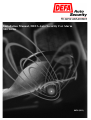
1
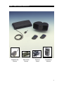
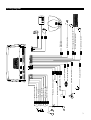
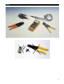
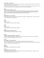
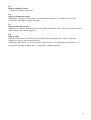
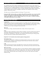
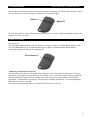
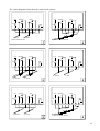
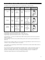
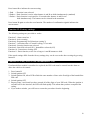
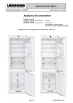
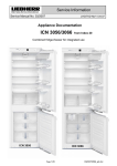
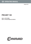
Installation Manual, DEFA Auto Security Car Alarm
800 Series
8028 (D11)
1
DEFA Auto Security 800 Series
Glassbreake
Sensor
Microwave
Sensor
Backup
Alarm
Immobilizer
Module
8028 (D10)
2
"
50
Green, unlock NO
Violet, unlock NC
P1.7
Red/white, +12V output
P1.1
-
+
25 A
P3.4
P3.1
4
P3
1
Grey/red, light output 1
Grey, door switch 1
7
14
P4.5
P4.6
P4.7
Grey/black, light output 2 P4.14
Red, +12V
P3.2
Black/grey, bonnet switch
Red/black, Starter kill input
1
4
P2
Black, ground P3.3
White/green, Starter kill output
White/orange, lock NC
P1.2
P1.3
P1.4
Yellow, unlock COM
Black/white, ground output
White/brown, lock NO
P1.6
P1.8
White/blue, lock COM
P1.5
5
8
P1
P4
8
1
2
P4.11
P4.12
P4.4
1
3
1
Black, siren
Black, siren
2
P6
P7
P8
Grey/white, doorswitch 2
White/red, auxiliary equipment
White, luggage compartment switch
White/brown, ignition
1
P6 P7 P8
P4.10
P4.8
P4.9
P5
15
Wiring diagram
3
Tools
4
Contents
Wiring diagram
Instructions for wiring diagram
Preparations for installation
Positioning of the Alarm Units
Attention!
User instructions
Coding new Remote Control Units
Connection of Central Locking
Programming of alarm
Technical data
Approval
Page 3
Page 6-8
Page 9
Page 9-10
Page 10
Page 11-12
Page 13
Page 13-14
Page 15-19
Page 20
Page 20
5
Instructions for the wiring diagram
---
Further information, see technical manual.
P-1
Connection of Central Locking
cf. page 6
P-2
Multiplug, Backup Alarm, Immobilizer Module and Pager (auxiliary equipment)
This is the connection for auxiliary equipment such as the DEFA Backup Alarm,
the DEFA Immobilizer Module or the Pager (Remote Alarm). Cf. separate assembly instructions.
P-3.1
Current supply, red lead
To be connected to a distributor via a 25A fuse (fuse box).
P-3.2
Input, starter kill, red/black lead (only applies to 821X models)
Separate control current lead from the ignition lock to the starter (connection 50) near the ignition lock.
Connect the lead end coming from the starter with P-3.2 red/black lead.
P-3.3
Ground, black lead
Connect directly to the vehicle body. Important: lead must not be extended.
P-3.4
Output, starter kill, white/green lead (only applies to 821X models)
The other lead end (50) leading to the starter is connected to P-3.4 white/green lead.
P-4.1
Channel 3
Output for the Remote Control of the electric DEFA Car Heating System. When activated, the output
supplies +12V until the function is deactivated again. Maximum load: 350 mA.
P-4.2
Channel 2
When activated, the output is grounded until the button is pressed. Use as required. Maximum load:
350 mA.
P-4.3
Channel 1
Output for electrical luggage compartment opener. When activated, the output is grounded for 1
second. This functions only when the alarm is switched off. Maximum load: 350 mA.
P-4.4
Auxiliary equipment, white/red lead
This alarm loop protects integrated auxiliary equipment in the car such as radio/cassette players or
similar equipment. The circuit is normally closed (NC) and triggers the alarm when interrupted.
P-4.5
6
Door trigger 1, grey lead
This input is normally open (NO) triggers the alarm when a contact to ground is made. Connect to the
existing door switch circuit of the car.
If the car has two separate circuits from the front and rear interior illumination, door trigger 2 (P-4.12)
can be used for the rear doors, and input P-4.5 can be used for the front doors.
P-4.6
Bonnet trigger, black/grey lead
This input is normally open (NO) and triggers the alarm when connected to ground, i.e. when the
bonnet is opened. Install DEFA Bonnet Switch. This should be installed in such a position as to
make it inaccessible from either the underside or the front of the car.
P-4.7
Light output 1, grey/red lead
Connected directly to the right turn signal lamp circuit in the car. Maximum load: 7.5 amp. (90 watt).
Fused with automatic circuit breaker.
P-4.8
Siren
Output to Siren.
Connect the two Siren leads to P4.8 and P4.9.
P-4.9
Siren
Output to Siren.
Connect the two Siren leads to P4.8 and P4.9.
P-4.10
Ignition signal, white/brown lead
Connect lead to ignition output of ignition switch.
P-4.11
Luggage compartment trigger, white lead
Connect to the normal luggage compartment switch if it is switched to ground. If it is switched to
positive, a DEFA Polarity Inverter must be used.
P-4.12
Door trigger 2, grey/white lead
This input is normally open (NO), and triggers the alarm when contacted to ground
This is an additional door switch input for NEGATIVE switches and is used particularly when there are
separate circuits for the front and rear doors.
P-4.13
DEFAnet
This output can control DEFA Power Module.
P-4.14
Light output 2, grey/black lead
Connected directly to the left turn signal lamp circuit in the car. Maximum load: 7.5 amp. (90 watt).
Fused with automatic circuit breaker.
7
P-5
Plug for auxiliary Sensors
Cf. separate assembly instructions.
P-6
Plug for Glassbreake Sensor
Standard for all models with the letter G in the model designation. If a window is broken, the
Glassbreake Microphone triggers the alarm.
P-7
Plug for Microwave Sensor
Standard for all models with the letter M in the model designation. If the sensor detects motion in the
vehicle interior, the alarm is triggered.
P-8
Plug for LED
Universal LED bracket: The LED can be installed on the instrument panel, on the A-pillar, the
windscreen or at any other position desired.
Embedded LED bracket: Use an 8.0 mm drill if the bracket is to be embedded in metal plates, a 7.5 8.0 mm drill for plastic material and a 7.0 mm drill for padding material.
8
Preparations for installation
Further information, see technical manual.
The workshop always holds complete responsibility for performing all necessary safety measures on
installation of the alarm system. Observe any instructions issued by the car manufacturer. Before making
any connections, use a voltmeter/multimeter to check the connection points. Always ensure that the
connection points are well insulated by using, for example, shrinkdown plastic tubing or insulation tape.
Avoid installing connection points or installation components in the immediate vicinity of airbag
modules or other safety systems.
The alarm can act on all petrol and diesel cars having a 12V power source.
Important: DEFA alarm modules, series 820 (without DEFA Immobilizer), may only be installed
in vehicles with approved original Immobilizers; if this is not the case, the Alarm will not be
subject to type approval. A list of recognised original start lock systems is available from DEFA
or the DEFA representative in your country.
Positioning of the Alarm units
Central Unit
Attach the Central Unit below the instrument panel or at a suitable point in the vehicle interior using
plastic fastening strips. The Central Unit should not be visible, and should be as inaccessible as possible.
Important: The Central Unit must be installed with its plugs facing downwards to ensure that
condensation water cannot run along the cables into the unit.
Main fuse
The main fuse (25 amp.) should be attached in the vicinity of the current power source.
Siren
Install in the engine compartment, exposed as little as possible to spray water and heat from exhaust or
turbocharger components (minimum distance 30 cm). The Siren aperture must face downwards to
prevent water accumulating in it. Important: Never install the Siren with the aperture facing upwards.
The Siren must not be accessible from the underside of the car.
Important: Never install the Siren with the aperture facing upwards.
Glassbreake Sensor
The Glassbreake Microphone is installed on the instrument panel or in the centre console. Clean the
installation surface with a grease dissolving agent and then fasten the Glassbreake Sensor with the
enclosed double-sided adhesive tape.
LED
Install in instrument panel using the embedded bracket or fasten to the instrument panel/windscreen
using a universal bracket or double-sided adhesive tape. The LED must be clearly visible from outside.
Microwave Sensor
The preferred location is at the centre of the car roof, 40 cm from the windscreen, under the roof lining.
If this is not possible, it can be installed in the centre console. The sensor can be installed behind plastic
covers but not behind metal covers, as these would block the waves from the sensor. Please note that
some cars have a thin metal film in the roof lining. In these cases, the sensor must not be installed
behind this lining.
9
If the sensor is attached to the inside of the roof, the arrow with the mark UP is usually located on the
underside of the sensor and points towards the rear of the car interior.
If the sensor is attached to the centre console, the arrow with the mark UP is usually located on the side
of the sensor facing the interior.
The sensitivity of the sensor must be checked and, if necessary, adjusted after installation.
Important: Loose metal objects such as keys, coins, etc., can trigger the alarm if they are too
close to the sensor.
Antenna feed lead
The active (white) part of the antenna must be attached in as free a location as possible, and not in the
vicinity of metal or other leads. The position of the antenna is a major influence on its range.
Alarm signs (decals)
Attach DEFA Auto Security decals to both the front side windows and to the windscreen or rear
screen.
Important: The decals must not obscure the driver’s line of sight.
The sticker with details of the alarm model is attached in the glove compartment. The relevant model is
checked.
Attention!
•
•
•
•
The DEFA Auto Security Alarm Module should be installed in accordance with the
manufactorer’s instructions.
The selection of a good installer is recommended. The national distributor may be contacted
to indicate appropriate installers.
The installation certificate supplied with the alarm shall be completed by the installer.
Making any alterations or additions to the alarm will automatically invalidate the certificate
of installation.
10
User Instructions
Further information, see technical manual.
Your DEFA Auto Security Alarm is activated using the two buttons (A and B) on the Remote Control.
The two buttons are easy to tell apart, as button A is noticeably higher.
Button A
Button B
«Press» means that you press the button for a maximum of 1 second. «Hold» means that you press the
button for at least 2 seconds
Alarm ON (arm)
Press button A.
The turn signal lamps flash once and the alarm siren emits a «click» to confirm that the alarm is ON.
The LED illuminates for 20 seconds and then starts to flash, to confirm that the alarm and the
Glassbreake/Microwave Sensor are switched ON.
Press button A
Temporary deactivation of Sensors
You can also set the alarm to ON without activating the sensors for motion in the interior or impact
against the screen. This can be necessary if, for example, a pet is left in the vehicle. Quickly switch the
ignition ON and OFF again. Exit the vehicle and, within 30 seconds, press button A twice briefly
(maximum 3 seconds between pressing). The LED starts flashing immediately. The turn signal lamps
illuminate for approx. 1 second.
The sensors are reactivated when you switch ON the alarm the next time.
11
Alarm OFF (disarm)
Press button B.
The turn signal lamps flash twice to confirm that the alarm is OFF. The LED stops flashing.
Press button B
If the alarm was triggered during your absence, the turn signal lamps flash five times and the alarm siren
emits a «click» five times when the alarm is disarmed. The LED now flashes to indicate which sensor
had triggered the alarm. (cf. table page 16).
Emergency deactivation
If the Remote Control is broken or lost, deactivate the alarm as follows:
Your Emergency Code is:
DEFA Central Unit 821X
P/N:10011 D S/N: 1234567
PIN-kode: X- X- X- X- X
Manufactured by DEFA A.S, Norway
DEFA Hotline : 4732771540
1. Unlock and open the car door. The Alarm is activated !
2. Turn the ignition ON and OFF five times in a row.
The Led "flickers".
3. When you turn ON the ignition once again, the Led will
blink. Let the Led blink as many times as the first digit
of your PIN-kode, and turn OFF the ignition.
4. Turn ON the ignition and repeat the procedure until you
have gone through every digit in your PIN-kode.
The Alarm is now disarmed.
If you make a mistake, start over again at step 3.
Start the car immediately !
A. Consult your card with the PIN code and locate your five-digit PIN code (Personal Identification
Number)
B. Follow the instructions on the emergency code card
Important: If you make a mistake, you can repeat the procedure from 3. onwards as often as required.
Important: Don’t forget - keep your PIN Code on your person. Do not leave it in the car!
12
Coding of new Remote Control Units
Further information, see technical manual.
A
Press button B to switch the alarm and the Immobilizer (if present) OFF. The
emergency deactivation can also be used.
B
Switch the ignition ON and OFF 5 times. The LED flashes rapidly.
C
When you switch the ignition ON again, the LED should flash. Allow the LED
to flash as many times as the first number of your PIN code and then switch
the ignition OFF again (the LED stops flashing).
D
Switch the ignition ON again and repeat the procedure until all digits of the
PIN code have been entered.
E
The LED flashes rapidly. If you make a mistake, start again at «C» with the
first digit of the PIN code.
F
Switch the ignition ON again and press buttons A and B of the Remote Control
Unit being programmed simultaneously (one Remote Control Unit at a time).
Press both buttons until you receive the sound and light confirmation.
G
Switch the ignition OFF once all Remote Control Units have been coded.
Important: Coding the keys deletes the old codes, A maximum of 4 Remote Control Units can be
coded.
Connection of Central Locking
Further information, see technical manual.
P-1
Multiplug, Central Locking
Plug for connection of the Central Locking, cf. diagram, page 14
The plug for the Central Locking P-1 must be configured (assigned) for the relevant car. If the function
of the Central Locking is unclear, the original circuit diagrams for the car must be consulted. Always
check with a voltmeter/multimeter before making any connections. The leads in the P-1 plug which are
not used must be disconnected or insulated.
Important: Each relay in the Central Unit can be loaded with a maximum of 15 amps. The
Central Unit can become damaged if correctly wired or overloaded. Output P-1.1 is fused by an
automatic circuit breaker.
P-1
Plug
P1.1
P1.2
P1.3
P1.4
P1.5
P1.6
P1.7
P1.8
Function
Battery +
Lock NC
Ground
Unlock COM
Lock COM
Lock NO
Unlock NO
Unlock NC
Colour
Red/white
White/orange
Black/white
Yellow
White/blue
White/brown
Green
Lilac
13
The circuit diagrams below show the usual circuit options.
LOCK
UNLOCK
+12V
+12V
15A
GND
1
4
8
7
BLUE
5
2
6
UNLOCK
LOCK
GND
15A
1
3
4
8
7
2
5
6
3
GREEN
To DEFA central lock motor
A : LOCK AND UNLOCK
1
+12V
UNLOCK
LOCK
+12V
GND
15A
1
4
8
7
5
2
4
6
UNLOCK
GND
15A
3
1
4
8
7
5
2
6
3
A : LOCK
B : UNLOCK
B : UNLOCK
LOCK
A : LOCK
2
+12V
UNLOCK
LÅS
+12V
15A
GND
1
4
B : UNLOCK
8
7
5
2
5
6
UNLOCK
LOCK
GND
15A
3
1
A : LOCK
4
8
7
5
2
6
3
A : LOCK AND UNLOCK
3
6
14
Programming the alarm
Further information, see technical manual.
The alarm contains a register that allows various functions to be programmed or altered using the
Remote Control and the ignition key. Please read the detailed function description on the following
pages.
Function
1
2
3
4
5
6
7
8
9
10
11
12
13
Description
Cause of Alarm trigger
Number of Remote Controls
Alarm sounds
Passive arming
The sensitivity of the Microwave Sensor
Remote Control with Slider Switch
Central locking - time
Central locking - security function
Starter kill/Immobilizer
Convenience locking
Panic function (Remote triggering of alarm)
Production settings
Entry of PIN code for Immobilizer
Definition of pressing and holding programming buttons on Remote Control :
Press means: press for a maximum of 1 second.
Hold means: press for at least 2 seconds.
Procedure for programming:
A)
Switch the ignition ON and OFF five times. The LED flashes rapidly.
B)
Switch the ignition ON again, allow the LED to flash twice and switch the
ignition OFF again. Repeat 5 times. After the fifth time, the LED will flash
rapidly when the ignition is switched OFF again.
C)
Switch the ignition ON. Press button A to activate function 1. The function that
is active is indicated by the number of sound signals.
D)
Pressing button A again activates the next function. Hold button A to return to
the previous function.
E)
Once you have reached the desired function, you can program or alter the
function as described on pages 16, 17, 18 and 19.
F)
If you want to program some more functions, press button A. You can then
select the function by either pressing or holding button A.
G)
Once you have completed programming, switch the ignition OFF.
15
Function 1: Cause of Alarm trigger
Press button A to obtain information about the cause of the alarm last triggered. Press button B for
information about the alarm triggered previously. Hold button B to return to the last alarm.
Hold buttons A and B simultaneously to delete the trigger cause memory.
The Central Unit can store up to 10 alarm events.
Alarm triggered by:
Number of flashes
Auxiliary Sensor 1
2
Open door
3
Open bonnet
4
Open luggage compartment lid
5
Ignition
6
Attempt to remove secured object (stereo, ski box, etc.)
7
Microwave Sensor
8
Glassbreake Sensor
9
Auxiliary Sensor 2
10
Function 2: Number of Remote Control Units
Press button B to learn how many Remote Control Units are connected to the alarm. The number of
units is indicated by the number of flashes.
Function 3: Alarm sounds
Press button B to activate the set alarm sound for 5 seconds. Press button B again to select the next
alarm sound and hold button B to return to the previous sound. A total of 6 different sounds are
available.
Function 4: Passive arming
Passive arming means that the alarm is switched on 12 seconds after the ignition is switched off and the
doors are closed.
Press button B to indicate:
1 flash if active arming is selected
2 flashes if active arming is selected regardless of the opened door.
3 flashes if passive arming is selected.
Press button B again to select the next function. The number of confirmation sounds indicates the status
currently set.
Function 5: The sensitivity of the Microwave Sensor
For Control purposes the sensitivity level of the detector is indicated by a number (1- 8) of short signals
in the LED.The lowest level is 1, the highest is 8. Factory setting is 3.
Press button B to indicate the valid sensitivity level. Press button B to increases the sensitivity level
while holding button B reduces the level. The number of flashes in the LED indicates the level. Selected
sensitivity level is confirmed by releasing the detector. Last choosen step will be selected sensitivity
level.
16
Function 6: Setting of Remote Control with Slider Switch
The Remote Control with Slider Switch can be programmed for 3 different modes:
Programming
Press A
Hold A
Press B
Hold B
1 flash
Alarm
ON
Close
windows
Alarm
OFF
Windows open
2 flashes
Alarm
ON
Close sliding
roof
or
Channel 2
3 flashes
(Standard)
Alarm
ON
Close tilted
sliding roof
or
Channel 3.
(Car heating
ON)
Alarm
OFF
Alarm
OFF
Position of
Slider Switch
Open sliding
roof
or
Channel 1.
(Open luggage
compartment)
Tilt sliding roof
or
Channel 3.
(Car heating
OFF)
Programming 1 provides the functions in line 1 of the table
Programming 2 provides the functions in lines 1 and 2 of the table
Programming 3 provides the functions in lines 1, 2 and 3 of the table
If programming 1 is selected, the middle and top Slider Switch positions can be used to operate the
alarms in 2 other cars.
If programming 2 is selected, the top Slider Switch position can be used to operate the alarm in one
other cars.
If only the electric window winders are to be operated, the original Remote Control can be used (1:1).
A Remote Control with Slider Switch is not required.
A precondition for programming is that the Remote Control has been coded with the Slider Switch in
the bottom position.
Press button B to indicate the programming of the Slider Switch: 1 signal corresponds to point 1, 2
signals to point 2 and 3 signals to point 3. Press button B again to select the next programming
procedure or hold button B to select the preceding programming procedure. The number of
confirmation signals indicates the selected programming procedure.
17
Function 7: Time for Central Locking
Press button B to indicate the current Central locking pulse factor.
1 flash = 1 second pulse
2 flashes = 4 seconds pulse
3 flashes = 0.5 seconds pulse
Press button B again to select the next pulse length, hold button B to select the preceding factor. The
number of confirmation signals indicates the selected pulse factor programmed.
Function 8: Security functions of Central locking
Press button B to indicate the current setting. When this function is selected, it prohibits activation of
the alarm until you have exited the vehicle. This function is intended for vehicles with a locking system
for the Central Locking.
1 flash = Security function not selected (Standard)
2 flashes = Security function selected
Press button B again to select the next function. The number of confirmation signals indicates the
current status.
Function 9: Start lock/Immobilizer
Press button B to indicate the current setting.
Starter kill: The lock function is switched on at the same time as the alarm is armed and is deactivates
as soon as the alarm is switched off again.
Immobilizer: This locking function is activated automatically 30 seconds after the ignition is switched
off and a door is opened. The Immobilizer is deactivated when you switch off the alarm. If you do not
start the car within 30 seconds after opening the doors, the Immobilizer is activated again.
1 flash = Immobilizer is selected (standard on 823)
2 flashes = Starter kill is selected (standard on 821)
Press button B again to select the Immobilizer, hold button B to select the start lock. The number of
confirmation signals indicates the current status.
Function 10: Convenience closing
Switching on the alarm can simultaneously lock the doors and close the sliding roof.
Press button B to indicate the current setting.
1 flash = Function is not selected (standard)
2 flashes = Convenience closing via the original system
3 flashes = Convenience closing via DEFA Power Module, closes only electric window winders
Press button B again to select the next convenience closing mode or hold button B to select the
preceding one. The number of confirmation signals indicates which convenience closing mode is
selected.
Application of function: Hold button A until all elements are closed.
Function 11: Panic function
18
Press button B to indicate the current setting.
1 flash = Function is not selected
2 flashes = Panic function is active when buttons A and B are held simultaneously (standard)
3 flashes = Panic function is activated for 30 seconds after buttons A and B were
held simultaneously. The buttons can be released in the meantime.
Press button B again to select the next function. The number of confirmation signals indicates the
current status.
Function 12: Factory settings
The following settings are provided ex works:
Function 3: Alarm sound no. 1
Function 4: Active arming
Function 6: Programming of all functions (setting 3)
Function 7: Activation time of Central Locking; 0.5 seconds
Function 8: Security function not selected
Function 9: Start lock selected (821). Immobilizer selected (823)
Function 10: Convenience closing; OFF
Function 11: Panic function, active for as long as A and B buttons are held
If the actual settings differ from the factory settings, they can be reset to the above settings by pressing
button B.
Function 13: Entry of PIN code in Immobilizer Unit
If an Immobilizer module is retrofitted or replaced, the PIN code must be entered into the alarm to
allow the vehicle to be started.
1. Press button B
2. Switch ignition OFF
3. Switch ignition ON, allow LED to flash the same number of time as the first digit of the Immobilizer
PIN code
4. Switch ignition OFF
5. Repeat points 3 and 4 until you have entered all of the digits of your PIN code. When the ignition is
switched off for the last time, the LED will flash rapidly. This means that you have completed the
coding.
6. If you make a mistake, you will have to restart the procedure from the beginning.
19
Technical data
Central Unit, 800 series
Operating voltage: 9-15 V d.c.
Operating temperature: -40°C to +85°C
Exterior dimensions: 159 x 80 x 34 mm
Power consumption
820/821X-G:
820/821X-M:
820/821X-MG:
820/821X-MG Backup
823X-MG:
Armed
Disarmed
13 mA
19 mA
19 mA
29 mA
19 mA
18 mA
18 mA
18 mA
35 mA
18 mA
Approval
The EEC approval mark will be affixed on a label that is placed on the rear side of all the units
approved.
20