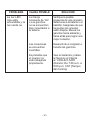
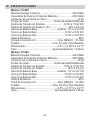
1
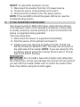
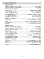
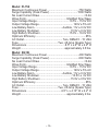
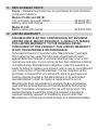
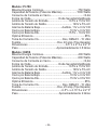
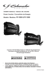
OWNER’S MANUAL
Manual del usuario
Models / Modelos:
PI-200, PI-400, PI-750, XI41B
Power Inverter
Convertidor de Energía
Converts 12V DC Battery Power
to 120V AC Household Power
Convierte la Energía de Baterías de 12V de CC
a 120V de CA de Energía Doméstica
DO NOT RETURN THIS PRODUCT TO THE STORE!
Call Customer Service for assistance: 800-621-5485
¡NO LO DEVUELVA este producto A LA TIENDA!
Llame a Servicios al Cliente para asistencia: 800-621-5485
READ THE ENTIRE MANUAL BEFORE USING THIS PRODUCT. FAILURE TO DO SO COULD RESULT IN
SERIOUS INJURY OR DEATH.
LEA EL MANUAL COMPLETO ANTES DE UTILIZAR ESTE
PRODUCTO. CUALQUIER FALLA PODRÍA RESULTAR EN
SERIAS LESIONES O PODRÍA SER MORTAL.
0099001246-00
IMPORTANT:READ AND SAVE THIS SAFETY AND INSTRUCTION
MANUAL.
SAVE THESE INSTRUCTIONS – This manual will show you how
to use your inverter safely and effectively. Please read, understand
and follow these instructions and precautions carefully, as this
manual contains important safety and operating instructions. The
safety messages used throughout this manual contain a signal
word, a message and an icon.
The signal word indicates the level of the hazard in a situation.
Indicates an imminently hazardous situation which, if
not avoided, will result in death or serious injury to the
operator or bystanders.
Indicates a potentially hazardous situation which, if not
avoided, could result in death or serious injury to the
operator or bystanders.
Indicates a potentially hazardous situation which, if not
avoided, could result in moderate or minor injury to the
operator or bystanders.
Indicates a potentially hazardous situation which, if not
avoided, could result in damage to the equipment or
vehicle or property damage.
Pursuant to California Proposition 65, this product
contains chemicals known to the State of California to
cause cancer and birth defects or other reproductive
harm. Wash hands after handling.
1.
IMPORTANT SAFETY INSTRUCTIONS –
SAVE THESE INSTRUCTIONS.
This manual contains important safety and operating instructions.
Risk of electric shock or fire.
1.1 Keep out of reach of children.
1.2 Keep the inverter well ventilated in order
to properly disperse heat generated while it
is in use. Make sure there are several inches
of clearance around the top and sides and do
not block the slots of the inverter.
•2•
1.3 Make sure the inverter is not close to any potential source of
flammable fumes or clothing.
1.4 Do not place the inverter in areas such as battery compartments
or engine compartments where fumes may accumulate.
1.5 Keep the inverter dry.
1.6 DO NOT allow the inverter to come into contact with rain or moisture.
1.7 DO NOT operate the inverter if you, the inverter, the device being
operated or any other surfaces that may come into contact with
any power source are wet. Water and many other liquids can
conduct electricity, which may lead to serious injury or death.
1.8 Do not place the inverter on or near heating vents, radiators or
other sources of heat or flammable materials.
1.9 Do not place the inverter in direct sunlight. The ideal air
temperature for operation is between 50° and 80°F.
1.10 Only connect the power inverter to a 12-volt accessory outlet. Do
not attempt to connect the inverter to any other power source,
including an AC power source. Connecting to a 6-volt or 16-volt
battery will cause damage to the inverter.
1.11 Make sure the AC plug connection is tight.
1.12 Do not modify the inverter in any way including cables, plugs or
switches as it may result in property damage or personal injury.
1.13
Incorrect operation of your inverter may result in
damage and personal injury. The inverter output is 120V AC and
can shock or electrocute the same as any ordinary household AC
wall outlet.
1.14 Do not open – no user serviceable parts inside.
1.15 This device does not include an internal Ground Fault Circuit
Interrupter (GFCI).
2.
BEFORE USING YOUR POWER INVERTER
NOTE: This inverter is designed to be used with a single battery,
up to group 31 (130 Ah or smaller). The recommended source of
power is a 12 volt deep cycle battery, due to their high reserve
capacity. Automotive batteries are recommended for only a short
period of time of an hour or less.
•3•
NOTE: Do not use the inverter with a product that draws a higher
wattage than the inverter can provide, as this may cause damage to
the inverter and product.
When you turn on a device or a tool that runs on a motor, the device
basically goes through two stages:
1. Start Up – Requiring an initial surge of power (commonly
known as the “starting or peak load”).
2. Continuous Operation – Power consumption drops (commonly
known as the “continuous load”).
The wattage (WATTS) or amperes (AMPS) can normally be found
stamped or printed on most devices and equipment, or in the
user’s manual. Otherwise, contact the manufacturer to find out
whether the device you want to use is compatible with a modified
sine wave.
To calculate the wattage: Wattage = AMPS x 120 (AC Voltage).
To calculate the starting load: Starting Load = 2 x WATTS. In
general, the start up load of the device or power tool determines
whether your inverter has the capability to power it.
To calculate the continuous load: Continuous Load = AMPS x 120
(AC Voltage).
Always run a test to establish whether the inverter will
operate a particular piece of equipment or device. In the event of a
power overload, the inverter is designed to automatically shut down.
This safety feature prevents damaging the inverter while testing
devices and equipment within the wattage range of the inverter.
When using the vehicle’s 12 volt accessory port, this
inverter is designed to supply 60 to 70 watts when the vehicle is
not running. With the vehicle’s engine running, it can supply up to
100 watts. To use the full output, you must connect the inverter
directly to your battery.
NOTE: The 100 watt limit is to accommodate the fuse ratings
for all vehicles. Some vehicles may allow the full output. If the
fuse blows when you switch on the device you are trying to use,
you have to either use a smaller device or you must connect the
inverter directly to the battery.
•4•
This inverter uses a nonsinusoidal waveform.
Therefore, we do not recommend you use it to power the
following devices:
1. Switch mode power supplies
2. Linear power supplies
3. Class 2 transformers
4. Line filter capacitors
5. Shaded pole motors
6. Fan motors
7. Microwave ovens
8. Fluorescent and high intensity lamps (with a ballast)
9. Transformerless battery chargers
Doing so may cause the device to run warmer or overheat.
3.
FASTENING THE INVERTER TO A FLAT SURFACE
For convenience, your inverter can be fastened to a flat surface,
horizontally or vertically. The area where the inverter is to
be fastened must be dry, well ventilated and away from any
combustible material or fumes.
1. Turn off and disconnect the inverter.
2. Place the back of the inverter with the mounting bracket
against a secure and flat surface.
3. Attach the inverter to the flat surface using corrosion-resistant
screws.
4.
CONNECTING INVERTER CABLES
The inverter and power source must be in the OFF mode.
Make sure you connect your inverter to a 12-volt
power supply only.
Inverter connection (Models PI-400, PI-750 and XI41B):
1. Locate the positive and negative plastic terminals located on the
back of the inverter and remove the terminal caps completely.
2. Install the positive (red) cable ring lug onto the positive (red)
terminal screw. Install the negative (black) cable ring lug onto
the negative (black) terminal screw. Tighten each terminal, so
that the cable cannot come loose.
•5•
Connecting inverter cable to a vehicle (100 watts maximum)
[All models]:
1. Remove the cigarette lighter from its outlet.
2. Push the 12-volt power plug firmly into the outlet.
Connecting inverter cables to 12V battery or 12V power source
(Models PI-400, PI-750 and XI41B):
1. Keep hands, hair, clothing and jewelry clear of battery terminals.
2. Wear eye protection and protective clothing.
3. Connect the positive (red) inverter terminal cable to the
power source positive (+) or battery terminal. Make sure the
connection is secure.
4. Connect the negative (black) inverter terminal cable to the
power source negative (-) or battery terminal. Make sure the
connection is secure.
5. To disconnect the inverter, reverse the above steps.
NOTE: The internal speaker may make a brief “beep” when the
inverter is being connected to or disconnected from the 12-volt
power source.
Failure to make the correct connections will result in
blown fuses and permanent damage to the inverter.
5.
OPERATING INSTRUCTIONS
1. Connect the inverter (see “CONNECTING INVERTER
CABLES” section).
2. Make sure the device to be operated is turned OFF.
3. Plug the device into the inverter AC outlet.
4. Switch the inverter’s ON/OFF switch to the ON position.
5. Turn the device on.
6. To disconnect, reverse the above procedure.
NOTE: If more than one device is to be powered, start one device
at a time to avoid a power surge and overloading the inverter.
The surge load of each device should not exceed the inverter’s
Continuous Operation wattage rate.
•6•
If you are using the power inverter to operate a
battery charger, monitor the temperature of the battery charger for
about 10 minutes. If the battery charger becomes abnormally
warm, disconnect it from the inverter immediately.
NOTE: You can use an extension cord from the inverter to the
device without significantly decreasing the power being generated
by the inverter. For best operating results, the extension cord
should be no longer than 50 feet.
Using the Inverter to operate a TV or audio device:
The inverter is shielded and filtered to minimize signal
interference. Despite this, some interference may occur with your
television picture, especially with weak signals. Below are some
suggestions to try and improve reception.
1. Make sure the television antenna produces a clear signal
under normal operating conditions (i.e. at home plugged into
a standard 120-volt AC wall outlet). Also, ensure that the
antenna cable is adequately shielded and of good quality.
2. Try altering the position of the inverter, antenna cables, and
television power cord. Add an extension cord from the inverter
to the TV so as to isolate its power cord and antenna cables
from the 12-volt power source.
3. Try coiling the television power cord and the input cables
running from the 12-volt power source to the inverter.
4. Affix one or several “Ferrite Data Line Filters” to the television
power cord. Ferrite Data Line Filters can be purchased at
most electronic supply stores.
NOTE: You may hear a “buzzing” sound being emitted from
inexpensive sound systems when operated with the inverter. This
is due to ineffective filters in the sound system’s power supply.
Unfortunately, this problem can only be resolved by purchasing a
sound system with a higher quality power supply or higher quality filter.
•7•
6.
POWER SOURCE
To get the best performance out of your inverter, we recommend that
you use it with the vehicle’s engine running.
Your average automobile or marine battery at full charge will provide
an ample power supply to the inverter for approximately 3 hours when
the engine is off. The actual length of time the inverter will function
depends on the age and condition of the battery and the power
demand being placed by the device being operated with the inverter.
If you decide to use the inverter while the engine is off, we
recommend you turn OFF the device plugged into the inverter
before starting the engine. To maintain battery power, start the
engine every 2 to 3 hours and let it run for approximately 10
minutes to recharge the battery.
Although it is not necessary to disconnect the inverter when turning
over the engine, it may briefly cease to operate as the battery
voltage decreases. While the inverter draws very low amperage
when not in use, it should be unplugged to avoid battery drain.
7.
LED INDICATOR AND SHUTDOWN PROTECTION
The LED glows GREEN automatically when plugged into a 12-volt
DC source, but will not glow under the following conditions:
1. When the power input from the vehicle’s battery drops to
approximately 10-volts, low battery shutdown occurs and
inverter shuts off. Solution: Recharge or Replace the battery.
2. When the power input from the vehicle’s battery exceeds
15-volts, high voltage overload protection occurs. Solution:
Reduce the voltage range to between 12-volts and 14-volts.
3. The continuous load demand from the equipment or device
being operated exceeds the continuous load rating of the
inverter being used. Solution: Use a higher capacity inverter
or lower rated device.
4. The case temperature becomes hot (exceeds 145°F).
Solution: Allow the inverter to cool. Do not block the cooling
slots or air flow over and through the inverter. Reduce the
load on the inverter to the continuous rated output.
•8•
RESET: To reset after shutdown occurs:
1. Disconnect the inverter from the 12V power source.
2. Check the source of the problem and correct.
3. Reconnect the inverter to the 12V power source.
NOTE: If the red LED is lit and the green LED is not, see the
Troubleshooting section.
8.
IF THE INVERTER FUSE BLOWS
Your power inverter is fitted with a fuse, which should not have
to be replaced under normal operating conditions. A blown fuse
is usually caused by reverse polarity or a short circuit within the
device or equipment being operated.
If the fuse does blow:
1. Disconnect the device or equipment immediately.
2. Find the source of the problem and repair it.
3. Install a new fuse (25-amp for Models PI-200, PI-400 and
XI41B; 45-amp for Model PI-750). The fuse can be found on
the right side of the inverter. NOTE: If you are using the 12V
accessory plug to power the inverter, there is also a 15-amp
fuse in the end of the plug.
Do not install a fuse with a higher amp rating than
the original fuse, as this may damage the inverter and any product
you use with the inverter. Make sure to correct the cause of the
blown fuse before using the inverter again.
•9•
9.
Troubleshooting
PROBLEM
Red LED is on,
audible alarm
is on, and/or
inverter does not
function.
The red LED is
lit and the green
LED is not.
REASON
SOLUTION
Poor contact at
terminals.
Unplug and reinsert the
12-volt plug or check
connections at power supply.
Fuse blown.
See “IF THE INVERTER
FUSE BLOWS” section.
Inverter
shutdown.
See “LED INDICATOR
AND SHUTDOWN
PROTECTION” section.
Inverter may
not be working
properly.
See Warranty and call
Customer Service
1-800-621-5485 (Hours:
7:00 am – 5:00 pm CST).
12V Accessory
plug or clips are
not making a
good connection
to the battery.
Check for poor connection
to battery and frame. Make
sure connection points
are clean. Rock clips
back and forth for a better
connection.
Connections are
reversed.
Unplug the charger and
reverse the clips.
Inverter may
not be working
properly.
See Warranty and call
Customer Service
1-800-621-5485 (Hours:
7:00 am – 5:00 pm CST)
• 10 •
10. SPECIFICATIONS
Model: PI-200
Maximum Continuous Power...........................................200 Watts
Surge Capability (Peak Power)........................................400 Watts
No Load Current Draw........................................................... <0.3A
Wave Form.......................................................Modified Sine Wave
Input Voltage Range...........................................10.5V – 15.5V DC
Output Voltage Range.............................................. 120V ± 5% AC
Low Battery Alarm......................................Audible, 11V ± 0.3V DC
Low Battery Shutdown..........................................10.5V ± 0.3V DC
High Battery Shutdown.........................................15.5V ± 0.5V DC
Optimum Efficiency.................................................................. 85%
AC Outlet.................................................... One, NEMA 5 - 15 USA
Fuse.....................................................One, 25-Amp (Spade Type)
Dimensions.............................................. 6.5" L x 3.38" W x 2.2" H
Weight...........................................................approximately 1.6 lbs.
Model: PI-400
Maximum Continuous Power...........................................400 Watts
Surge Capability (Peak Power)........................................800 Watts
No Load Current Draw........................................................... <0.4A
Wave Form.......................................................Modified Sine Wave
Input Voltage Range...........................................10.5V – 15.5V DC
Output Voltage Range.............................................. 120V ± 5% AC
Low Battery Alarm......................................Audible, 11V ± 0.3V DC
Low Battery Shutdown............................................10.5V ± .3V DC
High Battery Shutdown.........................................15.5V ± 0.5V DC
Optimum Efficiency.................................................................. 85%
AC Outlet.................................................... Two, NEMA 5 - 15 USA
Fuse.....................................................Two, 25-Amp (Spade Type)
Dimensions.............................................. 6.5" L x 4.13" W x 2.2" H
Weight..............................................................approximately 2 lbs.
• 11 •
Model: PI-750
Maximum Continuous Power...........................................750 Watts
Surge Capability (Peak Power)......................................1500 Watts
No Load Current Draw........................................................... <0.4A
Wave Form.......................................................Modified Sine Wave
Input Voltage Range...........................................10.5V – 15.5V DC
Output Voltage Range.............................................. 120V ± 5% AC
Low Battery Alarm......................................Audible, 11V ± 0.3V DC
Low Battery Shutdown..........................................10.5V ± 0.3V DC
High Battery Shutdown.......................................15.0V – 16.0V DC
Optimum Efficiency.................................................................. 85%
AC Outlet.................................................... Two, NEMA 5 - 15 USA
Fuse.....................................................Two, 45-Amp (Spade Type)
Dimensions................................................... 8.5" L x 4" W x 2.2" H
Weight...........................................................approximately 3.5 lbs.
Model: XI41B
Maximum Continuous Power...........................................400 Watts
Surge Capability (Peak Power)........................................800 Watts
No Load Current Draw........................................................... <0.4A
Wave Form.......................................................Modified Sine Wave
Input Voltage Range...........................................10.5V – 15.5V DC
Output Voltage Range.............................................. 120V ± 5% AC
Low Battery Alarm......................................Audible, 11V ± 0.3V DC
Low Battery Shutdown............................................10.5V ± .3V DC
High Battery Shutdown.........................................15.5V ± 0.5V DC
Optimum Efficiency.................................................................. 85%
AC Outlet.................................................... Two, NEMA 5 - 15 USA
Fuse.....................................................Two, 25-Amp (Spade Type)
Dimensions.............................................. 6.5" L x 4.13" W x 2.2" H
Weight..............................................................approximately 2 lbs.
• 12 •
11. REPLACEMENT PARTS
Fuses – Replacement fuses can be purchased at most electronic
component retailers.
Models PI-400 and XI41B:
12V accessory plug with cables................................ 38-99-001511
Battery cable with clamps......................................... 38-99-001512
Model PI-750:
Battery cable with clamps......................................... 38-99-001534
12. LIMITED WARRANTY
SCHUMACHER ELECTRIC CORPORATION, 801 BUSINESS
CENTER DRIVE, MOUNT PROSPECT, IL 60056-2179, MAKES
THIS LIMITED WARRANTY TO THE ORIGINAL RETAIL
PURCHASER OF THIS PRODUCT. THIS LIMITED WARRANTY
IS NOT TRANSFERABLE OR ASSIGNABLE.
Schumacher Electric Corporation (the “Manufacturer”) warrants
this inverter for two years from the date of purchase at retail
against defective material or workmanship that may occur under
normal use and care. If your unit is not free from defective material
or workmanship, Manufacturers obligation under this warranty is
solely to repair or replace your product, with a new or reconditioned
unit, at the option of the Manufacturer. It is the obligation of the
purchaser to forward the unit, along with proof of purchase and
mailing charges prepaid to the Manufacturer or its authorized
representatives in order for repair or replacement to occur.
Manufacturer does not provide any warranty for any accessories
used with this product that are not manufactured by Schumacher
Electric Corporation and approved for use with this product. This
Limited Warranty is void if the product is misused, subjected to
careless handling, repaired, or modified by anyone other than
Manufacturer or if this unit is resold through an unauthorized retailer.
• 13 •
Manufacturer makes no other warranties, including, but not limited
to, express, implied or statutory warranties, including without
limitation, any implied warranty of merchantability or implied
warranty of fitness for a particular purpose. Further, Manufacturer
shall not be liable for any incidental, special or consequential
damage claims incurred by purchasers, users or others associated
with this product, including, but not limited to, lost profits,
revenues, anticipated sales, business opportunities, goodwill,
business interruption and any other injury or damage. Any and all
such warranties, other than the limited warranty included herein,
are hereby expressly disclaimed and excluded. Some states do
not allow the exclusion or limitation of incidental or consequential
damages or length of implied warranty, so the above limitations or
exclusions may not apply to you. This warranty gives you specific
legal rights and it is possible you may have other rights which vary
from this warranty.
THIS LIMITED WARRANTY IS THE ONLY EXPRESS LIMITED
WARRANTY AND THE MANUFACTURER NEITHER ASSUMES
OR AUTHORIZES ANYONE TO ASSUME OR MAKE ANY
OTHER OBLIGATION TOWARDS THE PRODUCT OTHER
THAN THIS WARRANTY.
Schumacher Electric Corporation Customer Service
1-800-621-5485
Monday – Friday 7:00 a.m. to 5:00 p.m. CST
To activate the warranty, please fill in the warranty registration card on page 15 and
mail it in, OR go to www.batterychargers.com to register your product online.
DO NOT RETURN THIS PRODUCT TO THE STORE!
Call Customer Service for assistance: 800-621-5485
• 14 •
• 15 •
DESCRIPTION:___________________________
Schumacher Electric Corporation
801 Business Center Drive
Mount Prospect, IL 60056-2179
Serial Number________________________(SEE PRODUCT)
Store Location_____________________UPC Number_________________________
Store Name Where Purchased____________________Date of Purchase__________
Phone______________________Email____________________________________
City_________________________________State__________Zip Code__________
Street Address________________________________________________________
Name_______________________________________________________________
Mail To:
The warranty card should be submitted within 30 days of purchase. The customer must
keep the ORIGINAL receipt because it will be required for any warranty claims.
This warranty is not transferable.
This is the only express limited warranty, and the manufacturer neither assumes nor authorizes
anyone to assume or make any other obligation. There is no other warranty, other than what is
described in the product owner’s manual.
MODEL:___________________
2 YEAR LIMITED
WARRANTY PROGRAM
REGISTRATION
• 16 •
Schumacher Electric Corporation
801 Business Center Drive
Mount Prospect, IL 60056-2179
Código de barras ________________________(CONSULTE EL PRODUCTO)
Localización de la Tienda___________________Numero de Serie _______________
Nombre de la Tienda donde se Compró_________________Fecha de compra _____
Tel:_______________________Correo electrónico____________________________
Ciudad_______________________________Estado_____________C.P.__________
Dirección_____________________________________________________________
Nombre______________________________________________________________
Enviar a:
La tarjeta de garantía debe enviarse durante los primeros 30 días después de la compra.
El cliente debe mantener el recibo de compra ORIGINAL como comprobante,
el cual le otorga todo derecho a cualquier reclamo de garantía.
Esta garantía no es transferible.
Esta es la única garantía limitada expresa, y el productor no autoriza ni otorga a alguien a realizar
alguna otra obligación. No existe ninguna otra garantía más que la descrita en el manual del dueño.
MODELO:___________________ DESCRIPCIÓN:___________________________
PROGRAMA DE REGISTRO
DE 2-AÑOS DE GARANTÍA
LIMITADA
IMPORTANTE: LEA Y GUARDE ESTE MANUAL DE
INSTRUCCIONES Y SEGURIDAD.
GUARDE ESTAS INSTRUCCIONES – Este manual le mostrará
cómo utilizar su convertidor en forma segura y efectiva. Por
favor, lea, comprenda y siga estas instrucciones y precauciones
cuidadosamente, ya que este manual contiene instrucciones
operativas y de seguridad de importancia. Los mensajes de
seguridad representados en este manual contienen palabras guía,
un mensaje y una figura.
La palabra guía indica el nivel de peligro en determinada situación.
Indica una inminente situación de riesgo que, si no se
evita, resultaría mortal o de serios perjuicios al operador
o personas alrededor.
Indica una situación potencialmente riesgoso que, si
no se evita, podría resultar o de serios perjuicios al
operador o personas alrededor.
Indica una situación potencialmente peligrosa que, de
no evitarse, podría resultar en menores o serio daños al
usuario y terceras personas.
Indica una situación potencialmente peligrosa que, de
no evitarse, podría causar daño al equipo, al vehículo y
propiedades alrededor.
Conforme a la propuesta 65 de California, este
producto contiene químicos de los cuales en el
Estado de California tiene conocimiento que provocan
cáncer y malformaciones congénitas u otras lesiones
reproductivas. Lávese las manos después de usar.
1.
INSTRUCCIONES IMPORTANTES DE SEGURIDAD –
GUARDE ESTAS INSTRUCCIONES. Este manual contiene
instrucciones operativas y de seguridad de importancia.
El riesgo de descarga eléctrica
o incendio.
1.1 Manténgase alejado de los niños.
1.2 Mantenga el convertidor bien ventilado
para dispersar apropiadamente el calor
• 17 •
generado cuando está en uso. Asegúrese de que haya varias
pulgadas de libramiento alrededor de la parte superior y lados y
no bloquee las ranuras del convertidor.
1.3 Asegúrese de que el convertidor no esté cerca de ninguna fuente
potencial de gases inflamables o ropa.
1.4 No coloque el convertidor en áreas tales como compartimientos
de baterías o compartimientos del motor donde los vapores o
gases pueden acumularse.
1.5 Mantenga el convertidor seco.
1.6 NO OPERE el convertidor si usted, el convertidor, el dispositivo a
ser operado o cualquier otra superficie puede entrar en contacto
con cualquier fuente de energía que está húmeda. El agua y
muchos otros líquidos pueden conducir electricidad, lo cual puede
llevar a una lesión seria o la muerte.
1.7 NO OPERE el convertidor si usted, el convertidor, el dispositivo
a ser operado o cualquier otra superficie que puede entrar en
contacto con cualquier fuente de energía está húmeda. El agua y
muchos otros líquidos pueden conducir electricidad, lo cual puede
llevar a una lesión seria o la muerte.
1.8 No coloque el convertidor sobre o cerca de ventilas de calefacción,
radiadores u otras fuertes de calor o materiales inflamables.
1.9 No coloque el convertidor en la luz directa del sol. La temperatura
del aire ideal para la operación es entre 50° y 80°F.
1.10 Solamente conecte el convertidor de energía a una toma de
corriente accesoria de 12V. No intente conectar el convertidor
a cualquier otra fuente de energía, incluyendo una fuente de
energía de CA (corriente alterna). El conectarlo a una batería de
6V o 16V dañará el convertidor.
1.11 Asegúrese de que la clavija de CA y/o la conexión USB estén
ajustadas.
1.12 Por ningún motivo modifique el inversor, incluyendo cables,
enchufes o interruptores debido a que podría causar daños
materiales o personales muy serios.
1.13
La operación incorrecta de su convertidor puede
resultar en daño y lesión personal. La salida del convertidor es
de 120V CA y puede dar una descarga o electrocutar igual que
cualquier toma de corriente de pared doméstica de CA ordinaria.
• 18 •
1.14 No abrir – no contiene partes que el usuario pueda reparar.
1.15 Este dispositivo no incluye un Interruptor de Circuito con Conexión
a Tierra (GFCI por sus siglas en inglés) interno.
2.
ANTES DE USAR SU Inversor DE ENERGÍA
NOTA: Este inversor ha sido diseñado para ser usado con una
sola batería hasta el grupo 31 (130 Ah o menos). La fuente de
energía recomendada debe ser de una batería de ciclo profundo
de 12 voltios, debido a sus altas reservas de energía. Las baterías
regulares para automóviles son recomendadas sólo por un corto
período de tiempo de una hora o menos.
NOTA: No utilice el inversor con un producto que absorba mayor
cantidad de watts que el inversor pueda proveer, esto podría
causar daño al inversor y al producto.
Cuando usted enciende un dispositivo o una herramienta que
funciona con un motor, el dispositivo básicamente pasa a través
de dos etapas:
1. Arranque – Requiriendo una subida inicial de voltaje
(comúnmente conocida como “carga de inicio o pico”).
2. Operación Continua – El consumo de energía desciende
(comúnmente conocido como la “carga continua”).
El vataje (WATTS) o amperaje (AMPS) pueden ser encontrados
normalmente estampados o impresos en la mayoría de los
dispositivos y equipo, o en el manual del usuario. Por lo demás,
comuníquese con el fabricante para averiguar si el dispositivo que
usted quiere usar es compatible con una onda senoidal modificada.
Para calcular el vataje: Vataje = AMPS x 120 (Voltaje CA).
Para calcular la carga de arranque: Carga de Arranque =
2 x WATTS. En general, la carga de arranque del dispositivo
o herramienta eléctrica determina si su convertidor tiene la
capacidad de hacerlo funcionar.
Para calcular la carga continua: Carga Continua = AMPS x 120
(Voltaje CA).
• 19 •
Siempre corra una prueba para establecer si el
convertidor operará una pieza particular de equipo o dispositivo.
En caso de una sobrecarga de corriente, el convertidor está
diseñado para apagarse automáticamente. Ésa característica
de seguridad evitar dañar el convertidor mientras se prueban
dispositivos y equipo dentro del ámbito de vataje del convertidor.
Mientras el vehículo no se encuentre en marcha,
si se usa el Puerto de 12 volts, el Inversor está dideñado para
suministrar de 60 a 70 watts. En Marcha, puede llegar a abastecer
hasta 100 watts. Para usar la máxima potencia de salida, usted
debe conectar el inversor directo a la batería.
NOTA: El límite de 100 watts es para adaptar la proporción del
fusible a todos los vehículos. Algunos vehículos pueden permitir la
salida. Si el fusible se funde cuando cambie al aparato que intenta
usar, solo tiene dos opciones: Usar un aparato más pequeño o así
conectar el inversor directamente a la batería.
Este inversor usa ondas solenoids. Por lo tanto, no
recomendamos para operar los siguientes aparatos:
1. Fuentes energía de en forma de conmutador
2. Líneas de corriente eléctrica
3. Transformadores clase2
4. Condensadores de capacidad
5. Motores ligeros.
6. Motores de ventilador
7. Hornos de microondas
8. Lámparas flourescentes y de alta intensidad (con balastra)
9. Cargadores de baterías sin tranformador
Al hacerlo podría operar el aparato bajo intenso calor y
sobrecalentarlo.
• 20 •
3.
PARA SUJETAR EL CONVERTIDOR A UNA
SUPERFICIE PLANA
Por comodidad, su convertidor puede ser sujetado a una
superficie plana, horizontal o verticalmente. El área donde el
convertidor será sujetado debe ser seca, bien ventilada y estar
alejada de cualquier material o gases combustibles.
1. Apague y desconecte el convertidor.
2. Coloque la parte posterior del convertidor con el soporte de
montaje contra una superficie segura y plana.
3. Sujete el convertidor a la superficie plana usando tornillos
resistentes a la corrosión.
4.
PARA CONECTAR LOS CABLES DEL Inversor
El Inversor y la fuente de energía deben estar en el modo
APAGADO (OFF).
Asegúrese de conectar su Inversor a una fuente de
energía de 12V solamente.
Conexión del Inversor (Modelos PI-400, PI-750 y XI41B):
1. Ubique las terminales plásticas positiva y negativa localizadas
en el lado derecho del Inversor y quite completamente las
tapas de las terminales.
2. Instale el anillo del cable positivo (rojo) en el tornillo de la
terminal positiva (roja). Instale el anillo del cable positivo
(negro) en el tornillo de la terminal positiva (negra). Apriete
cada terminal para que el cable no pueda soltarse.
Para conectar el cable del Inversor a un vehículo
(100 watts máximo) [Todos los modelos]:
1. Quite el encendedor de cigarrillos de su toma de corriente.
2. Empuje la clavija de 12V firmemente en la toma de corriente.
• 21 •
Para conectar los cables del Inversor a una batería de 12V
o una fuente de energía de 12V (Modelos PI-400, PI-750
y XI41B):
1. Mantenga las manos, cabello, ropa y joyería alejados de las
terminales de la batería.
2. Usé protección para ojos y protección para la ropa.
3. Conecte el cable de la terminal positiva (rojo) del Inversor
a la fuente de energía positiva (+) o terminal de la batería.
Asegúrese de que la conexión sea segura.
4. Conecte el cable de la terminal negativa (negro) del Inversor
a la fuente de energía negativa (-) o terminal de la batería.
Asegúrese de que la conexión sea segura.
5. Para desconectar el Inversor, invierta los pasos anteriores.
NOTA: La bocina interna puede hacer breve “bip” cuando el
Inversor está siendo conectado a o desconectado de la fuente de
energía de 12V.
El no hacer las conexiones correctas resultará en
fusibles quemados y daño permanente el Inversor.
5.
INSTRUCCIONES DE OPERACIÓN
1. Conecte el Inversor (ver la sección “PARA CONECTAR LOS
CABLES DEL INVERSOR”).
2. Asegúrese de que el dispositivo a ser operado este
APAGADO (OFF).
3. Conecte el dispositivo en la toma de corriente CA del Inversor.
4. Encienda el inversor de ON/OFF a la posición de
encendido ON.
5. Enciende el dispositivo.
6. Para desconectar, invierta el procedimiento anterior.
NOTA: Si se va a dar energía a más de un dispositivo, inicie un
dispositivo a la vez para evitar una sobretensión de energía y
sobrecargar el Inversor. La sobretensión de cada dispositivo no debe
exceder el ámbito de vataje de Operación Continúa el Inversor.
Si usted esta usando el Inversor de energía
para operar un cargador de baterías, monitoree la temperatura
• 22 •
del cargador de baterías por aproximadamente 10 minutos.
Si el cargador de baterías se pone anormalmente caliente,
desconéctelo del Inversor inmediatamente.
NOTA: Usted puede utilizar una extensión del inversor al aparato
sin disminuir la carga generada por el inversor. Para obtener
mejores resultados en la operación, la extension no debe
sobrepasar 50 pies de largo.
Para usar el Inversor para operar una televisión o dispositivo
de sonido:
El Inversor está protegido y filtrado para minimizar la interferencia
con la señal. A pesar de esto, alguna interferencia puede ocurrir
con la imagen de su televisión, especialmente con señales débiles.
Abajo y algunas sugerencias para tratar y mejorar la recepción.
1. Asegúrese de que la antena de televisión produzca una señal
clara bajo condiciones normales de operación (Ej. en casa
conectado en una toma de corriente de pared estándar
de 120V de CA). También, asegúrese de que el cable de
la antena este protegido adecuadamente y que sea de
buena calidad.
2. Trate de alterar la posición del Inversor, los cables de la antena
y el cable de corriente de la televisión. Agregue un cable de
extensión del Inversor a la televisión para aislar el cable de
energía y los cables de la antena de la fuente de energía de 12V.
3. Intente enrollar el cable de energía de la televisión y los cables
de aporte que van de la fuente de energía de 12V al Inversor.
4. Fije uno o varios “Filtros de Línea de Datos de Ferrita” al
cable de energía de la televisión. Los Filtros de Línea de
Datos de Ferrita pueden comprarse la mayor parte de las
tiendas de partes electrónicas.
NOTA: Usted puede escuchar un sonido de “zumbido”
siendo emitido de sistemas de sonido baratos cuando son
operados con el Inversor. Esto es debido a filtros inefectivos
en el abastecimiento de energía del sistema de sonido.
Lamentablemente, este problema solamente puede ser resuelto
comprando un sistema de sonido con una calidad más alta de
abastecimiento de sonido o un filtro de más alta calidad.
• 23 •
6.
FUENTE DE ENERGÍA
Para obtener el mejor rendimiento de su inversor, le recomendamos
que se use mientras se ejecuta el motor del vehículo.
Su batería de automóvil o marina promedio a toda carga
proporcionará un abastecimiento de energía amplio para él
Inversor por aproximadamente dos a tres horas cuando el motor
está apagado. El tiempo total que el Inversor funcionará depende
de la edad y condición de la batería y de la demanda de energía
colocada por el dispositivo siendo operado con el Inversor.
Si decide usar el Inversor mientras el motor está apagado, le
recomendamos que apague el dispositivo conectado al Inversor
antes de arrancar el motor. Para mantener la energía de la
batería, arranque el motor cada hora o dos y déjelo encendido por
aproximadamente 10 minutos para recargar la batería.
Aunque no es necesario desconectar el Inversor cuando arranca
de nuevo el motor, puede dejar de operar brevemente mientras
disminuye el voltaje de la batería. Aunque el Inversor extrae muy
poco amperaje cuando no está en uso, debe ser desconectado
para evitar descargar la batería.
7.
INDICADOR LED Y PROTECCIÓN DE DE APAGADO
El LED brilla VERDE automáticamente cuando se conecta a
una fuente de 12V de CD, pero no brillará bajo las siguientes
condiciones:
1. Cuando la aportación de energía de la batería del vehículo
disminuye aproximadamente 10V, o un apagado por batería
baja y el convertidor se apaga. Solución: Recargue o
reemplace la batería.
2. Cuando la aportación de energía de la batería del vehículo
excede 15V, la protección de sobrecarga de alto voltaje ocurre.
Solución: Reducir el ámbito de voltaje a entre 12V y 14V.
3. La demanda de carga continua del equipo o dispositivo
siendo operado excede la clasificación de carga continua del
convertidor siendo usado. Solución: Usar un convertidor de
mayor capacidad o un dispositivo de clasificación más baja.
• 24 •
4. La temperatura de la caja se pone caliente (excede los 145°F).
Solución: Permita que el convertidor se enfríe. No bloquee las
ranuras de enfriamiento o el flujo de aire sobre y a través del
convertidor. Reduzca la carga sobre el convertidor a la salida
continua clasificada.
REINICIO: Para reiniciar en caso de ocurrir una interrupción:
1. Desenchufe el inversor de la fuente de alimentación de 12 volts.
2. Revise el origen del problema y corrija.
3. Vuelva a conectar el inversor a la fuente de alimentación de
12 volts.
NOTA: Si la luz LED roja está encendida y la luz verde no,
consulte la sección de localización y solución de problemas.
8.
SI SE QUEMA EL FUSIBLE DEL CONVERTIDOR
Su convertidor de corriente está equipado con un fusible, que
no tendría que ser reemplazado bajo condiciones normales de
operación. Un fusible quemado es causado usualmente por una
polaridad inversa como un cortocircuito dentro del dispositivo o
equipo siendo operados.
Si el fusible se quema:
1. Desconecte el dispositivo o equipo inmediatamente.
2. Encuentra la fuente del problema, y repárela.
3. Instale un nuevo fusible (de 25 amp para los Modelos PI-200,
PI-400 y XI41B; de 45 amp para el Modelo PI-750). El fusible
puede ser encontrado al final de la clavija en el convertidor.
NOTA: Si está utilizando el conector de 12V para alimentar el
inversor, también hay un fusible de 15 amperios en la punta
del enchufe.
Nunca instale un fusible con amperaje mayor que
el fusible original, ya que esto puede dañar el inversor y cualquier
aparato que utilice con el inversor. Asegúrese de corregir la causa
del fusible fundido antes de usar.
• 25 •
9.
RESOLUCIÓN DE PROBLEMAS
PROBLEMA
La LED
roja está
encendida,
la alarma
audible está
encendida, y/o
el convertidor
no funciona.
CAUSA POSIBLE
SOLUCIÓN
Mal contacto en
las terminales.
Desconecte y vuelva
a reinsertar la clavija
de 12V o revise las
conexiones a la fuente
de energía.
Fusible
quemado.
Ver la sección “SI SE
QUEMA EL FUSIBLE
DEL CONVERTIDOR”.
Cierre del
convertidor.
Es probable que
el inversor no
esté trabajando
propiamente.
• 26 •
Ver la sección
“INDICADOR LED Y
PROTECCIÓN DE
CIERRE”.
Vea la Garantía y llame
al Servicio al Cliente
al 1-800-621-5485
(Horario: De 7:00 a.m. a
5:00 p.m. CST [Tiempo
del Centro])
PROBLEMA
CAUSA POSIBLE
SOLUCIÓN
La luz LED
roja está
encendida y la
luz verde no.
La Clavija
Accesoria de 12V
o Los ganchos
no se encuentran
bien conectados a
la batería.
Verifique la posible
presencia de una conexión
defectuosa a la batería o al
bastidor. Asegúrese de que
los puntos de conexión
estén limpios. Mueva los
ganchos hacia adelante y
hacia atrás para lograr una
mejor conexión.
Las conexiones
se encuentran
invertidas.
Desenchufe el cargador e
invierta los ganchos.
Es probable que
el inversor no
esté trabajando
propiamente.
Vea la Garantía y llame
al Servicio al Cliente
al 1-800-621-5485
(Horario: De 7:00 a.m. a
5:00 p.m. CST [Tiempo
del Centro])
• 27 •
10. ESPECIFICACIONES
Modelo: PI-200
Máxima Energía Continua................................................200 Watts
Capacidad de Tensión (Potencia Máxima).......................400 Watts
Consumo de Corriente en Vacío............................................ <0.3A
Forma de Onda..................................... Onda Senoidal Modificada
Ámbito de Tensión de Entrada............................10.5V a 15.5V DC
Ámbito de Tensión de Salida a 13V........................... 20V ± 5% AC
Alarma de Batería Baja..............................Audible, 11V ± 0.3V CD
Cierre por Batería Baja.........................................10.5V ± 0.3V DC
Cierre por Batería Alta...........................................15.5V ± 0.5V DC
Óptima Eficiencia..................................................................... 85%
Toma de Corriente AC................................ Una, NEMA 5 - 15 USA
Fusible..................................................Uno, 25 amp (Tipo Espada)
Dimensiones.............................................. 6.5" L x 3.38" A x 2.2" P
Peso....................................................Aproximadamente 1.6 libras
Modelo: PI-400
Máxima Energía Continua................................................400 Watts
Capacidad de Tensión (Potencia Máxima).......................800 Watts
Consumo de Corriente en Vacío............................................ <0,4A
Forma de Onda..................................... Onda Senoidal Modificada
Ámbito de Tensión de Entrada............................10.5V a 15.5V DC
Ámbito de Tensión de Salida.................................... 120V ± 5% AC
Alarma de Batería Baja..............................Audible, 11V ± 0.3V CD
Cierre por Batería Baja.........................................10.5V ± 0.3V DC
Cierre por Batería Alta...........................................15.5V ± 0.5V DC
Óptima Eficiencia..................................................................... 85%
Toma de Corriente CA................................ Dos, NEMA 5 - 15 USA
Fusible..................................................Dos, 25 amp (Tipo Espada)
Dimensiones.............................................. 6.5" L x 4.13" A x 2.2" P
Peso.......................................................Aproximadamente 2 libras
• 28 •
Modelo: PI-750
Máxima Energía Continua................................................750 Watts
Capacidad de Tensión (Potencia Máxima).....................1500 Watts
Consumo de Corriente en Vacío............................................ <0.4A
Forma de Onda..................................... Onda Senoidal Modificada
Ámbito de Tensión de Entrada............................10.5V a 15,5V DC
Ámbito de Tensión de Salida.................................... 120V ± 5% AC
Alarma de Batería Baja..............................Audible, 11V ± 0.3V CD
Cierre por Batería Baja.........................................10.5V ± 0.3V DC
Cierre por Batería Alta.........................................15.5V – 16.0V DC
Óptima Eficiencia..................................................................... 85%
Toma de Corriente CA.................................Dos, NEMA 5 - 15 USA
Fusible..................................................Dos, 40 amp (Tipo Espada)
Dimensiones................................................... 8.5" L x 4" A x 2.2" P
Peso....................................................Aproximadamente 3.5 libras
Modelo: XI41B
Máxima Energía Continua................................................400 Watts
Capacidad de Tensión (Potencia Máxima).......................800 Watts
Consumo de Corriente en Vacío............................................ <0,4A
Forma de Onda..................................... Onda Senoidal Modificada
Ámbito de Tensión de Entrada............................10.5V a 15.5V DC
Ámbito de Tensión de Salida.................................... 120V ± 5% AC
Alarma de Batería Baja..............................Audible, 11V ± 0.3V CD
Cierre por Batería Baja.........................................10.5V ± 0.3V DC
Cierre por Batería Alta...........................................15.5V ± 0.5V DC
Óptima Eficiencia..................................................................... 85%
Toma de Corriente CA................................ Dos, NEMA 5 - 15 USA
Fusible..................................................Dos, 25 amp (Tipo Espada)
Dimensiones.............................................. 6.5" L x 4.13" A x 2.2" P
Peso.......................................................Aproximadamente 2 libras
• 29 •
11. PIEZAS DE REPUESTO
Fusibles – Fusibles de repuesto se pueden comprar en más
tiendas de componentes electrónicos.
Modelos PI-400 y XI41B
Clavija accesoria de 12V con cables........................ 38-99-001511
Cable de batería con abrazaderas............................ 38-99-001512
Modelo PI-750
Cable de batería con abrazaderas............................ 38-99-001534
12. GARANTÍA LIMITADA
SCHUMACHER ELECTRIC CORPORATION, 801 BUSINESS
CENTER DRIVE, MOUNT PROSPECT, IL 60056-2179, DA
ESTA GARANTÍA LIMITADA AL COMPRADOR ORIGINAL AL
MENUDEO DE ESTE PRODUCTO. ESTA GARANTÍA LIMITADA
NO ES TRANSFERIBLE O ASIGNABLE.
Schumacher Electric Corporation (el “Fabricante”) garantiza este
Inversor por dos años a partir de la fecha de compra al menudeo
contra material defectuoso o trabajo de fabricación que pueda
ocurrir bajo el uso y cuidado normal. Si su unidad no está libre
de material o trabajo de fabricación defectuoso, la obligación del
Fabricante bajo esta garantía es únicamente reparar o reemplazar
su producto, con uno a unidad nueva o reacondicionada, a opción
del Fabricante. Es obligación del comprador enviar la unidad
con comprobante de compra y los gastos de envío prepagos al
fabricante o a sus representantes autorizados para que ésta se
pueda reparar o reemplazar.
El Fabricante no proporciona ninguna garantía para ningún
accesorio usado con este producto que no esté fabricado por
Schumacher Electric Corporation y aprobado para uso con este
producto. Esta Garantía Limitada es nula si el producto se emplea
mal, se sujeta a manejo descuidado, se repara o modifica por
alguien que no sea él Fabricante o si esta unidad se vuelve a
vender a través de un vendedor no autorizado.
• 30 •
El Fabricante no da ninguna otra garantía, incluyendo, pero
sin limitarse a, garantías expresas, implicadas o creadas por
la ley, incluyendo sin limitación, cualquier garantía implicada
de comercialización o garantía implicada de aptitud para un
propósito particular. Además, el Fabricante no será responsable
por cualesquier demandas por daño incidental, especial o de
consecuencia en que incurran los compradores, usuarios u
otros asociados con este producto, incluyendo, pero sin limitarse
a ganancias, ingresos, ventas anticipadas, oportunidades de
negocios, buena voluntad, interrupción de negocios perdidos
y cualquier otra lesión o daño. Cualquier las garantías, que no
sean las de la garantía limitada incluidas en el este, están por el
presente expresamente denegadas y excluidas. Algunos estados
no permiten la exclusión o limitación de daños incidentales o
de consecuencia o el largo de la garantía implícita, así que las
limitaciones o exclusiones anteriores pueden no ser aplicables para
usted. Esta garantía le da derechos legales específicos y es posible
que pueda tener otros derechos que varían de esta garantía.
ESTA GARANTÍA LIMITADA ES LA ÚNICA GARANTÍA LIMITADA
EXPRESA Y EL FABRICANTE NO ASUME NI AUTORIZA A NADIE
A ASUMIR O OFRECER NINGUNA OTRA OBLIGACIÓN HACIA
EL PRODUCTO QUE NO SEA ESTA GARANTÍA.
Servicio al Cliente de Schumacher Electric Corporation
1-800-621-5485
De Lunes a Viernes de las 7:00 a.m. 5:00 p.m. CST
Para hacer efectiva la garatía, por favor llene la tarjeta de garantía en página 16
y evíela, O, visite la página de internet www.batterychargers.com para registrar
su producto en la red.
¡NO LO DEVUELVA este producto A LA TIENDA!
Llame a Servicios al Cliente para asistencia: 800-621-5485
• 31 •