1
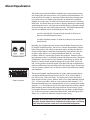
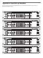
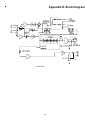
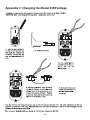
HA2500
HA2500 2
250 WATT BASS AMPLIFIERS
Hartke
Safety Instructions/Consignes de sécurité/Sicherheitsvorkehrungen/Instrucciones de seguridad
WARNING: To reduce the risk of fire or electric shock, do not expose this unit to rain
or moisture. To reduce the hazard of electrical shock, do not remove cover or back.
No user serviceable parts inside. Please refer all servicing to qualified personnel.The
lightning flash with an arrowhead symbol within an equilateral triangle, is intended to
alert the user to the presence of uninsulated "dangerous voltage" within the products
enclosure that may be of sufficient magnitude to constitute a risk of electric shock to
persons. The exclamation point within an equilateral triangle is intended to alert the
user to the presence of important operating and maintenance (servicing) instructions
in the literature accompanying the product.
Important Safety Instructions
1. Please read all instructions before operating the unit.
2. Keep these instructions for future reference.
3. Please heed all safety warnings.
4. Follow manufacturers instructions.
5. Do not use this unit near water or moisture.
6. Clean only with a damp cloth.
7. Do not block any of the ventilation openings. Install in accordance with the manufacturers instructions.
8. Do not install near any heat sources such as radiators, heat registers, stoves, or
other apparatus (including amplifiers) that produce heat.
9. Do not defeat the safety purpose of the polarized or grounding-type plug. A polarized plug has two blades with one wider than the other. A grounding type plug
has two blades and a third grounding prong. The wide blade or third prong is provided for your safety. When the provided plug does not fit your outlet, consult an
electrician for replacement of the obsolete outlet.
10. Protect the power cord from being walked on and pinched particularly at plugs,
convenience receptacles and at the point at which they exit from the unit.
11. Unplug this unit during lightning storms or when unused for long periods of time.
12. Refer all servicing to qualified personnel. Servicing is required when the unit has
been damaged in any way, such as power supply cord or plug damage, or if liquid
has been spilled or objects have fallen into the unit, the unit has been exposed to
rain or moisture, does not operate normally, or has been dropped.
ATTENTION: Pour éviter tout risque d’électrocution ou d’incendie, ne pas exposer
cet appareil à la pluie ou à l’humidité. Pour éviter tout risque d’électrocution, ne pas
ôter le couvercle ou le dos du boîtier. Cet appareil ne contient aucune pièce remplaçable par l'utilisateur. Confiez toutes les réparations à un personnel qualifié.
Le signe avec un éclair dans un triangle prévient l’utilisateur de la présence d’une
tension dangereuse et non isolée dans l’appareil. Cette tension constitue un risque
d’électrocution. Le signe avec un point d’exclamation dans un triangle prévient
l’utilisateur d’instructions importantes relatives à l’utilisation et à la maintenance du
produit.
Consignes de sécurité importantes
1. Veuillez lire toutes les instructions avant d’utiliser l’appareil.
2. Conserver ces instructions pour toute lecture ultérieure.
3. Lisez avec attention toutes les consignes de sécurité.
4. Suivez les instructions du fabricant.
5. Ne pas utiliser cet appareil près d’une source liquide ou dans un lieu humide.
6. Nettoyez l’appareil uniquement avec un tissu humide.
7. Veillez à ne pas obstruer les fentes prévues pour la ventilation de l’appareil.
Installez l’appareil selon les instructions du fabricant.
8. Ne pas installer près d’une source de chaleur (radiateurs, etc.) ou de tout équipement susceptible de générer de la chaleur (amplificateurs de puissance par
exemple).
9. Ne pas retirer la terre du cordon secteur ou de la prise murale. Les fiches canadiennes avec polarisation (avec une lame plus large) ne doivent pas être modifiées. Si votre prise murale ne correspond pas au modèle fourni, consultez votre
électricien.
10. Protégez le cordon secteur contre tous les dommages possibles (pincement,
tension, torsion,, etc.). Veillez à ce que le cordon secteur soit libre, en particulier
à sa sortie du boîtier.
11. Déconnectez l’appareil du secteur en présence d’orage ou lors de périodes
d’inutilisation prolongées.
12. Consultez un service de réparation qualifié pour tout dysfonctionnement (dommage sur le cordon secteur, baisse de performances, exposition à la pluie, projection liquide dans l’appareil, introduction d’un objet dans le boîtier, etc.).
ACHTUNG: Um die Gefahr eines Brandes oder Stromschlags zu verringern, sollten
Sie dieses Gerät weder Regen noch Feuchtigkeit aussetzen.Um die Gefahr eines
Stromschlags zu verringern, sollten Sie weder Deckel noch Rückwand des Geräts entfernen. Im Innern befinden sich keine Teile, die vom Anwender gewartet werden können. Überlassen Sie die Wartung qualifiziertem Fachpersonal.Der Blitz mit Pfeilspitze
im gleichseitigen Dreieck soll den Anwender vor nichtisolierter “gefährlicher Spannung”
im Geräteinnern warnen. Diese Spannung kann so hoch sein, dass die Gefahr eines
Stromschlags besteht. Das Ausrufezeichen im gleichseitigen Dreieck soll den Anwender
auf wichtige Bedienungs- und Wartungsanleitungen aufmerksam machen, die im mitgelieferten Informationsmaterial näher beschrieben werden.
Wichtige Sicherheitsvorkehrungen
1. Lesen Sie alle Anleitungen, bevor Sie das Gerät in Betrieb nehmen.
2. Bewahren Sie diese Anleitungen für den späteren Gebrauch gut auf.
PRECAUCION: Para reducir el riesgo de incendios o descargas, no permita que este
aparato quede expuesto a la lluvia o la humedad. Para reducir el riesgo de descarga
eléctrica, nunca quite la tapa ni el chasis. Dentro del aparato no hay piezas susceptibles
de ser reparadas por el usuario. Dirija cualquier reparación al servicio técnico oficial. El
símbolo del relámpago dentro del triángulo equilátero pretende advertir al usuario de
la presencia de “voltajes peligrosos” no aislados dentro de la carcasa del producto, que
pueden ser de la magnitud suficiente como para constituir un riesgo de descarga eléctrica a las personas. El símbolo de exclamación dentro del triángulo equilátero quiere
advertirle de la existencia de importantes instrucciones de manejo y mantenimiento
(reparaciones) en los documentos que se adjuntan con este aparato.
Instrucciones importantes de seguridad
1.
Lea todo este manual de instrucciones antes de comenzar a usar la unidad.
2.
Conserve estas instrucciones para cualquier consulta en el futuro.
3.
4.
5.
6.
7.
3.
4.
5.
6.
7.
8.
9.
10.
11.
12.
Bitte treffen Sie alle beschriebenen Sicherheitsvorkehrungen.
Befolgen Sie die Anleitungen des Herstellers.
Benutzen Sie das Gerät nicht in der Nähe von Wasser oder Feuchtigkeit.
Verwenden Sie zur Reinigung des Geräts nur ein feuchtes Tuch.
Blockieren Sie keine Belüftungsöffnungen. Nehmen Sie den Einbau des Geräts nur
entsprechend den Anweisungen des Herstellers vor.
Bauen Sie das Gerät nicht in der Nähe von Wärmequellen wie Heizkörpern,
Wärmeklappen, Öfen oder anderen Geräten (inklusive Verstärkern) ein, die Hitze
erzeugen.
Setzen Sie die Sicherheitsfunktion des polarisierten oder geerdeten Steckers nicht
außer Kraft. Ein polarisierter Stecker hat zwei flache, unterschiedlich breite Pole. Ein
geerdeter Stecker hat zwei flache Pole und einen dritten Erdungsstift. Der breitere
Pol oder der dritte Stift dient Ihrer Sicherheit. Wenn der vorhandene Stecker nicht
in Ihre Steckdose passt, lassen Sie die veraltete Steckdose von einem Elektriker
ersetzen.
Schützen Sie das Netzkabel dahingehend, dass niemand darüber laufen und
es nicht geknickt werden kann. Achten Sie hierbei besonders auf Netzstecker,
Mehrfachsteckdosen und den Kabelanschluss am Gerät.
Ziehen Sie den Netzstecker des Geräts bei Gewittern oder längeren Betriebspausen
aus der Steckdose.
Überlassen Sie die Wartung qualifiziertem Fachpersonal. Eine Wartung ist notwendig, wenn das Gerät auf irgendeine Weise, beispielsweise am Kabel oder
Netzstecker beschädigt wurde, oder wenn Flüssigkeiten oder Objekte in das Gerät
gelangt sind, es Regen oder Feuchtigkeit ausgesetzt war, nicht mehr wie gewohnt
betrieben werden kann oder fallen gelassen wurde.
8.
9.
10.
11.
12.
Cumpla con todo lo indicado en las precauciones de seguridad.
Observe y siga todas las instrucciones del fabricante.
Nunca utilice este aparato cerca del agua o en lugares húmedos.
Limpie este aparato solo con un trapo suave y ligeramente humedecido.
No bloquee ninguna de las aberturas de ventilación. Instale este aparato de acuerdo a las instrucciones del fabricante.
No instale este aparato cerca de fuentes de calor como radiadores, calentadores,
hornos u otros aparatos (incluyendo amplificadores) que produzcan calor.
No anule el sistema de seguridad del enchufe de tipo polarizado o con toma de
tierra. Un enchufe polarizado tiene dos bornes, uno más ancho que el otro. Uno
con toma de tierra tiene dos bornes normales y un tercero para la conexión a
tierra. El borne ancho o el tercero se incluyen como medida de seguridad. Cuando
el enchufe no encaje en su salida de corriente, llame a un electricista para que le
cambie su salida anticuada.
Evite que el cable de corriente quede en una posición en la que pueda ser pisado
o aplastado, especialmente en los enchufes, receptáculos y en el punto en el que
salen de la unidad.
Desconecte de la corriente este aparato durante las tormentas eléctricas o cuando
no lo vaya a usar durante un periodo de tiempo largo.
Dirija cualquier posible reparación solo al servicio técnico oficial. Deberá hacer
que su aparato sea reparado cuando esté dañado de alguna forma, como si el
cable de corriente o el enchufe están dañados, o si se han derramado líquidos o se
ha introducido algún objeto dentro de la unidad, si esta ha quedado expuesta a la
lluvia o la humedad, si no funciona normalmente o si ha caído al suelo.
Table of Contents
Introduction . . . . . . . . . . . . . . . . . . . . . . . . . . . . . . . . . . . . . . . . . . . . . . . . . . . . . . . . . . . . . . . . . . . . . . . . . . . . . 2
Features . . . . . . . . . . . . . . . . . . . . . . . . . . . . . . . . . . . . . . . . . . . . . . . . . . . . . . . . . . . . . . . . . . . . . . . . . . . . . . . . . 3
Guided Tour . . . . . . . . . . . . . . . . . . . . . . . . . . . . . . . . . . . . . . . . . . . . . . . . . . . . . . . . . . . . . . . . . . . . . . . . . . . . . . .
Front Panel . . . . . . . . . . . . . . . . . . . . . . . . . . . . . . . . . . . . . . . . . . . . . . . . . . . . . . . . . . . . . . . . . . . . . 4-5
Rear Panel . . . . . . . . . . . . . . . . . . . . . . . . . . . . . . . . . . . . . . . . . . . . . . . . . . . . . . . . . . . . . . . . . . . . . . . 6-7
Setting Up and Using the Model 2500 . . . . . . . . . . . . . . . . . . . . . . . . . . . . . . . . . . . . . . . . . . . . . . . . . . . 8-9
About Equalization . . . . . . . . . . . . . . . . . . . . . . . . . . . . . . . . . . . . . . . . . . . . . . . . . . . . . . . . . . . . . . . . . . .10-11
About Compression . . . . . . . . . . . . . . . . . . . . . . . . . . . . . . . . . . . . . . . . . . . . . . . . . . . . . . . . . . . . . . . . . . . . .12
Specifications . . . . . . . . . . . . . . . . . . . . . . . . . . . . . . . . . . . . . . . . . . . . . . . . . . . . . . . . . . . . . . . . . . . . . . . . . . . .13
Appendix A: Sound Set-up Templates . . . . . . . . . . . . . . . . . . . . . . . . . . . . . . . . . . . . . . . . . . . . . . . . . .14
Appendix A: Block Diagram . . . . . . . . . . . . . . . . . . . . . . . . . . . . . . . . . . . . . . . . . . . . . . . . . . . . . . . . . . . . . . .15
Appendix B: Changing the Model 2500 Voltage . . . . . . . . . . . . . . . . . . . . . . . . . . . . . . . . . . . . . . . . . . . .16
Copyright 2005 - 2006, Samson Technologies Corp.
Printed June, 2006 v1.2
Samson Technologies Corp.
45 Gilpin Avenue
Hauppauge, New York 11788-8816
Phone: 1-800-3-SAMSON (1-800-372-6766)
Fax: 631-784-2201
www.hartke.com
Introduction
Congratulations on purchasing the Hartke Model 2500 Bass Amplifier!
Although this unit is designed for easy operation, we suggest you first take
some time to go through these pages so you can fully understand how we’ve
implemented a number of unique features.
The Model 2500 provides 250 watts of power to a 4 ohm speaker system or
180 watts to an 8 ohm speaker system. With that kind of power, the Model
2500 is EXTREMELY loud and punchy. In addition, the Model 2500 offers a
number of additional advanced features, including front-panel compression
and graphic equalizers, effects send and return jacks, an effects send/return
balance knob, and a direct output with ground lift and pre or post EQ selection.
The Model 2500 is optimized for use with electric bass instruments. You’ll
find it to be an excellent bass amplifier for live performance use in small and
medium-size venues; in addition, the Model 2500’s advanced pre-amp features makes it ideal for use in recording environments.
In these pages, you’ll find a detailed description of the many features of the
Model 2500 bass amplifier, as well as a guided tour through it's front and
rear panels, step-by-step instructions for setting up and using your amplifier,
detailed discussions about equalization and compression, and full specifications. You’ll also find a warranty card enclosed—please don’t forget to fill it
out and mail it so that you can receive online technical support and so we
can send you updated information about these and other Hartke and Samson
products in the future.
SPECIAL NOTE: Should your unit ever require servicing, a Return
Authorization number (RA) is necessary. Without this number, the unit will
not be accepted. Please call Samson Technologies at (516) 932-1062 for a
Return Authorization number prior to shipping your unit. Please retain the
original packing material and, if possible, return the unit in its original carton
and packing materials.
2
Features
The Hartke Model 2500 bass amplifier offers all the newest concepts in bass
amplification. Here are some of its main features:
• Power to spare — The Model 2500, a full 250 watts delivered to a 4 ohm
speaker system or 180 watts to an 8 ohm speaker system.
• Our unique Transient Attack® circuitry which ensures that every nuance of
your bass performance is reproduced faithfully.
• Two Pre-Amp input knobs, allowing custom blending of solid state and tube
type sounds.
• Ten bands of high-quality graphic equalization, allowing you to create a
broad range of tonal colors for your bass instrument. A dedicated in/out
button allows you to preset an equalization curve.
• Two fully adjustable contour knobs (high pass and low pass), which provide
further control over shaping your bass sound.
• A built-in compressor which not only adds real “punch” to your bass sound,
but also allows you to smooth out volume differences between notes.
• Two independent inputs that accommodate both passive and active bass
guitars.
• Protection relay circuitry that protects connected speakers from dangerous
overloading and also prevents “thumps” when powering on or off.
• Effect loop send and return jacks that allow you to connect to professional
outboard effects processors.
• An effect Balance knob which enables you to adjust the relative amount of
Send (“dry”) versus Return (“wet”) effect signal being routed to the speaker
outputs.
• Electronically balanced direct output that provides a means of routing signal to professional mixing consoles in both live performance and recording
environments. A ground lift switch helps prevent hum or buzz from entering the signal, and a pre/post switch allows the direct signal to be derived
either before or after the amp EQ section.
• Rugged construction makes the Model 2500 eminently road-worthy.
3
Guided Tour - Model 2500 Front Panel
1
�
4
�
�
�
�
�
��
��
HA2500 2
��
�
1. Passive Input jack - If your bass guitar has passive circuitry, connect it to
the Model 2500 here. This standard, 1/4” unbalanced jack provides a high
impedance (100 k Ohms) input sensitivity of 20 millivolts.
2. Active Input jack - If your bass guitar has active circuitry,* connect it to the
Model 2500 here. This standard, 1/4” unbalanced jack provides a high impedance (100 k Ohms) input sensitivity of 60 millivolts.
3. Pre-Amp A (Tube Emulation) control - This determines the amount of preamplification being provided by special circuitry which delivers the sound
of a classic tube amplifier. Note that when both Pre-Amp knobs are used at
equal settings, the amplifier will be twice as loud as when only one is used.
Avoid setting both Pre-Amp knobs on maximum (“10”), since the result will
almost always be undesirable distortion.
4. Pre-Amp B (Solid State) control - This determines the amount of preamplification being provided by special circuitry which delivers the sound of a
solid state amplifier. Note that when both Pre-Amp knobs are used at equal
settings, the amplifier will be twice as loud as when only one is used. Avoid
setting both Pre-Amp knobs on maximum (“10”), since the result will almost
always be undesirable distortion.
* Bass guitars that have active circuitry normally require a battery for the circuitry to be functional.
4
Guided Tour - Model 2500 Front Panel
5. Compression control - This determines the amount of compression (peak
signal reduction) by simultaneously adjusting both threshold and compression ratio (which ranges from 2:1 to infinity [limiting]). At the fully counterclockwise “Off” position, the circuitry is bypassed and no compression is
applied (the knob clicks when set to the “Off” position). As the knob is raised
clockwise (at settings from “1” to “∞”) increasing amounts of compression are
applied. For more information, see the “About Compression” section on page
12 of this manual.
6. Graphic Equalizer In/Out switch - When pressed in (the “In” position), the
Model 2500’s graphic equalizer circuitry (as described in #7 below) is operational. When pressed out (the “Out” position), it is bypassed. The provision of
this switch allows you to set up a custom equalization curve (an equalization
“preset”) with the graphic EQ sliders, which can then be activated with the
press of a single button.
7. Graphic Equalizer - These sliders allow you to “draw” the tonal response of
the system by adding 15 dB of boost or attenuation to ten different narrowband frequency areas (30 Hz, 64 Hz, 125 Hz, 250 Hz, 500 Hz, 1 kHz, 2 kHz, 3
kHz, 5 kHz, and 8 kHz), affecting the main output signal of the Model 2500.
When a slider is at its center detented (“0”) position, the selected frequency
area is unaffected (it is said to be flat). When a slider is moved up (above
the “0” position, towards the “+15” position), the selected frequency area
is boosted, and when it is moved down (below the “0” position, towards the
“-15” position), the selected frequency area is attenuated. For more information, see the “About Equalization” section on pages 10 - 11 of this manual.
8. Contour Low Pass control - This acts as a broad-band low frequency equalizer, providing 18 dB of boost or attenuation at 100 Hz. You should generally
adjust this control (and the Contour High Pass control, described in #9 below)
prior to “fine-tuning” the system with the graphic equalizer (as described in #7
above). For more information, see the “About Equalization” section on pages
10 - 11 of this manual.
9. Contour High Pass control - This acts as a broad-band high frequency
equalizer, providing 18 dB of boost or attenuation at 10 kHz. You should
generally adjust this control (and the Contour Low Pass control, described
in #8 above) prior to “fine-tuning” the system with the graphic equalizer (as
described in #7 above). For more information, see the “About Equalization”
section on pages 13 - 14 of this manual.
10. Master Volume control - This is the overall volume control. For best signal-to-noise ratio, keep the output of your bass at or near maximum and
adjust the amp’s Master Volume to the desired level.
11. Power LED - Lights whenever the Model 2500 is powered on.
12. Power switch - Use this to power the Model 2500 on or off.
5
Guided Tour - Model 2500 Rear Panel
1
3
5
4
6
2
1. Fuse sled - This contains a fuse holder and shows the currently selected
voltage rating for your Model 2500. Make sure the voltage rating is correctly
set before powering up the amplifier! Fuse ratings are 10 amp for 115 vac and
6.2 amp for 230 vac. For information on how to change the voltage rating,
see Appendix B on page 14.
2. AC input - Connect the supplied standard 3-pin “IEC” plug here.
3. Fan - The fan provides vital cooling to your Model 2500. Make sure that it
is kept free of all obstructions and that cool, fresh air is accessible at all times.
Also, try to ensure that the Model 2500 is used in a dust-free environment.
4. Effect Return jack - Use this 1/4” unbalanced jack to return low impedance (600
ohm) signal to the Model 2500 from a professional outboard effects processor.*
6
Guided Tour - 2500 Rear Panel
5. Effect Send jack - Use this 1/4” unbalanced jack to send low impedance (100
ohm) signal from the Model 2500 to a professional outboard effects processor
such as a reverb, echo, chorus, flanger, or harmonizer device.* Output level is
approximately 0 dB to +4 dB and is post-EQ and post-compression but unaffected
by the setting of the Master Volume control. You can also use the Effect Send jack
to route signal to an external mixing console or amplifier with an input sensitivity
of +4 dB.
6. Speaker outputs - Connect any 4, 8, or 16 ohm bass cabinet(s) to these
standard unbalanced 1/4” jacks. WARNING: Because of the high power levels
and low frequency content of the signal generated by the Model 2500, use
only appropriately rated speaker cabinets (at least 250 watts at 4 ohms) that
are specifically designed for bass instruments. We recommend that Hartke
amplifiers be used with Hartke bass cabinets, although other brands of speakers can be used.
* In-line effects (such as footpedals) intended for low signal levels should be
placed between the bass and the amplifier Input and not connected with the
Effect Send and Return jacks.
** Note that the settings of the ten-band graphic equalizer will affect a “Post”
Direct Out signal regardless of the position of the front panel In/Out switch.
7
Setting Up and Using the Model 2500
Setting up your Hartke Systems 5500 Bass Amplifier is a simple procedure which
takes only a few minutes:
1. Remove all packing materials (save them in case of need for future service)
and decide where the amplifier is to be physically placed. To avoid potential
overheating problems, be sure that the rear panel is unobstructed and that there
is good ventilation around the entire unit, particularly behind the rear-panel fan.
2. Begin by hooking up your bass cabinet or cabinets, using the 1/4” unbalanced
Speaker output connectors on the rear panel; it is never a good idea to power up
any amplifier that is not connected to loudspeakers. We recommend the use of a
single 4 ohm cabinet or two 8 ohm cabinets. Hartke amps are optimized for use
with Hartke bass cabinets, although other brands of speakers can be substituted.
Any appropriately rated bass cabinet with a minimum impedance of 4 ohms (that
is, 4 ohms or greater) can be used. In order to ensure correct phase correlation,
the tip of the Model 2500 speaker jack should be connected to the “+” (hot) input
of your loudspeaker, and the sleeve of the Model 2500 speaker jack should be
connected to the “-” (ground) input of your loudspeaker.
WARNING: Hartke amplifiers can deliver very high power levels. Driven to
full power, they can damage connected loudspeakers, regardless of brand,
size, or configuration. Care should be taken not to strain connected loudspeakers as this can cause permanent damage and will degrade the performance of the entire system. If you see connected loudspeakers moving
excessively, turn your system down immediately or use the equalization and/
or compression controls to reduce the amount of subharmonic (extremely
low frequency) signal.
3. Next, connect the 3-pin AC plug into any grounded AC socket. Don’t turn the
amplifier on just yet, though.
PASSIVE
ACTIVE
4. Use a standard music instrument cable to connect your bass to the appropriate Input jack on the front panel (if your bass has active circuitry,* connect it to
the “Active” input; if not, connect it to the “Passive” input). On the front panel of
the Model 2500, set the Master volume control to “0” (fully counterclockwise)
and set both Pre-Amp A (Tube Emulation) and B (Solid State) knobs to “5” (the
twelve o’clock position). Set the Compression knob to its “Off” position (fully
counterclockwise—you’ll hear a click) and set both Contour knobs to their center
detented “0” position. Finally, set the graphic equalizer In/Out switch to its “Out”
position.
5. Press the front panel Power switch in order to turn on the amplifier.
After
approximately three seconds, you’ll hear a click, indicating that the relay protection circuitry has completed cycling and that power to the system has been provided.
6. Set the output of your bass to maximum and then, while playing, slowly turn
the Master volume control up until the desired level is achieved. If you hear distortion even at low amplifier Master volume settings, back off the output of your
bass (or check for a faulty cable).
* Bass guitars that have active circuitry normally require a battery for the circuitry to
be functional.
8
Setting Up and Using The Model 2500
7. Experiment with altering the balance of the two Pre-Amp knobs, listening to
the effect each has on the overall sound. Depending upon the specific instrument you are using and your personal taste, you may prefer the sound of one
over the other, or you may prefer a particular blend of the two. Note that, when
both are used at equal settings, the amplifier will be twice as loud as when only
one is used. In step #4 on the previous page, we recommended that you begin
with both knobs at their midway “5” setting, but the two Pre-Amp knobs can in
fact be set to any blend you like. However, you will usually want to avoid setting
both to their maximum “10” position since this setting will almost always result in
undesirable distortion.
8. When you have settled on a Pre-Amp balance, the next step is to adjust the
two Contour (bass and treble equalizer) controls to taste. For more information,
see the “About Equalization” section on page 10 of this manual. When you get
a great setting that complements your instrument and playing style, it’s a good
idea to write it down for future use.
9. Next, experiment with the Model 2500 graphic equalizer. Begin by setting
each of the ten sliders to their flat “0” center detented position. Then press in
the In/Out switch (to its “In” position) so that the graphic equalizer is activated.
Finally, move each slider in turn as you play your bass. For more information, see
the “About Equalization” section on page 10 of this manual. Again, when you get
a graphic equalization setting that complements your instrument and playing
style, it’s a good idea to write it down for future use.
10. Now try out the Model 2500 compression circuitry. Activate it by turning
the Compression knob clockwise from its “Off” position (you’ll hear a click when
it is activated). As you turn the knob clockwise, the input signal from your bass
becomes more and more severely compressed—you’ll hear peak signals (such
as string slaps and pulls) begin to sound increasingly “squashed,” relative to the
lower-level signals produced by standard playing. The result will be a decreased
dynamic range but an overall leveling of signal throughout the full pitch range of
your instrument. For more information, see the “About Compression” section on
page 12.
A
4
3
5
B
6
7
0
10
9
TUBE
30Hz
3
5
6
7
8 2
2
1
4
64Hz
125Hz
1
8
0
10
9
SOLID STATE
250Hz
500Hz
1KHz
2KHz
3KHz
5KHz
8KHz
+15
+12
+9
+6
+3
+2
+15
IN
0
-2
-3
-6
-9
-12
-15
OUT
-15
30Hz
64Hz
125Hz
250Hz
500Hz
1KHz
2KHz
3KHz
5KHz
8KHz
30Hz
64Hz
125Hz
250Hz
500Hz
1KHz
2KHz
3KHz
5KHz
8KHz
+15
+12
+9
+6
+3
+2
+15
IN
0
-2
-3
-6
-9
-12
-15
OUT
-15
30Hz
64Hz
125Hz
250Hz
500Hz
1KHz
2KHz
3KHz
5KHz
8KHz
30Hz
64Hz
125Hz
250Hz
500Hz
1KHz
2KHz
3KHz
5KHz
8KHz
+15
+12
+9
+6
+3
+2
+15
IN
0
-2
-3
-6
-9
-12
-15
OUT
-15
30Hz
64Hz
125Hz
250Hz
500Hz
1KHz
2KHz
3KHz
5KHz
8KHz
11. If you’re using an external signal processor, turn your Hartke amplifier off
momentarily and then connect a standard audio cable between the Effect Send
jack and your effects processor input and another standard audio cable between
the Effect Return jack and your effects processor output (if required, multiple
effects processors can be daisy-chained together, output to input). Then turn the
amp back on and play your bass while adjusting the controls of your outboard
effects processor(s). For best results, set both the input and output gain of all
connected effects processor(s) to 0 dB (unity gain), so that there is no increase or
decrease in level whether the effects are switched in or out.
If you have followed all the steps above and are still experiencing difficulties, call
Samson Technical Support (516-932-1062) between 9 AM and 5 PM EST.
9
Model 2500 Effect Send/Return jacks
About Equalization
The Hartke Systems Model 2500 Bass Amplifier gives you enormous control
over shaping the sound of your bass, using a process called equalization. To
understand how this works, it’s important to know that every naturally occurring sound consists of a broad range of pitches, or frequencies, combined
together in a unique way. This blend is what gives every sound its distinctive
tonal color. EQ controls allow you to alter a sound by boosting or attenuating
specific frequency areas—they operate much like the bass and treble controls
on your hi-fi amp, but with much greater precision. The Model 2500 provides
you with two different means for equalizing your bass sound:
30Hz
+15
64Hz
125Hz
250Hz
500Hz
1KHz
2KHz
3KHz
Contour controls
5KHz
8KHz
+15
+12
+9
+6
+3
+2
IN
0
-2
-3
-6
-9
-12
-15
OUT
-15
30Hz
64Hz
125Hz
250Hz
500Hz
1KHz
2KHz
3KHz
5KHz
8KHz
30Hz
64Hz
125Hz
250Hz
500Hz
1KHz
2KHz
3KHz
5KHz
8KHz
+15
+12
+9
+6
+3
+2
+15
IN
0
-2
-3
-6
-9
-12
-15
OUT
-15
30Hz
64Hz
125Hz
250Hz
500Hz
1KHz
2KHz
3KHz
5KHz
8KHz
5KHz
8KHz
Graphic equalizer
30Hz
64Hz
125Hz
250Hz
500Hz
1KHz
2KHz
3KHz
+15
+12
+9
+6
+3
+2
+15
IN
0
-2
-3
-6
-9
-12
-15
OUT
-15
30Hz
64Hz
125Hz
250Hz
500Hz
1KHz
2KHz
3KHz
5KHz
8KHz
•
Low Pass and High Pass Contour controls provide 18 dB of cut or
boost in two broad frequency bands.
•
A Graphic Equalizer provides 15 dB of cut or boost in ten narrow frequency bands.
Normally, you will adjust the two Contour controls before “fine-tuning” your
EQ with the Graphic Equalizer. The Low Pass Contour control affects a broad
band of frequencies with 100 Hz as the center point; similarly, the High Pass
Contour control affects a broad band of frequencies with 10 kHz as the center point. When either is in its center detented position (“0”), it is having
no effect. When it is moved right of center, the particular frequency area is
being boosted; when it is moved left of center, the frequency area is being cut
(“attenuated”). Because there is very little bass guitar energy at 10 kHz, the
High Pass Contour control should be thought of as your overall “noise” control—turning it down (to the left of the “0” position) will help to eradicate hiss
and buzz while having very little effect on the bass guitar signal. Similarly, the
Low Pass Contour control, when set left of 0, can be used to eliminate rumble
and “woofiness.”
The ten-band graphic equalizer provides ten sliders, each corresponding to
a single narrow frequency band (at 30 Hz, 64 Hz, 125 Hz, 250 Hz, 500 Hz, 1
kHz, 2 kHz, 3 kHz, 5 kHz, and 8 kHz). This allows you to “draw” the desired
tonal response of your system. When a slider is in its center detented position
(“0”), it is having no effect. When it is moved above center (towards “+15”),
the particular frequency area is being boosted; when it is moved below center
(towards “-15”), the frequency area is being attenuated. We carefully selected
these frequency areas because they have maximum impact on bass signals.
For example, the lowest slider (30 Hz) affects the very lowest audible frequencies (in fact, most humans cannot hear below 20 Hz), while the highest four
sliders (2, 3, 5, and 8 kHz) affect the “twang” of a bass string.
WARNING: Use caution when raising the 30 Hz slider above 0 if you are
operating at high volume levels (especially if Compression is not being
used) since this can place undue stress on connected loudspeakers.
10
About Equalization
To find out how each graphic equalizer slider affects the sound of your particular bass, start with all ten bands flat (that is, all ten sliders at their detented “0” center position). Then, one by one, raise and lower each slider, listening carefully to the effect of each. If you don’t specifically need to utilize
the ten-band graphic equalizer, bypass it by setting the In/Out switch to its
“Out” position. Alternatively, you can preset a custom graphic equalization
curve (for example, for a feature solo) and activate it simply by pressing the
switch when needed. Note that turning all EQ controls up the same amount
will have virtually the same effect as simply turning up the Master Volume;
conversely, turning them all down the same amount will have virtually
the same effect as turning down the Master Volume. Both approaches are
pointless (after all, that’s why we gave you a Master Volume control!)
In many instances, the best way to deal with equalization is to think in terms
of which frequency areas you need to attenuate, as opposed to which ones
you need to boost. Be aware that boosting a frequency area also has the
effect of boosting the overall signal; specifically, too much low frequency
EQ boost can actually cause overload distortion or even harm a connected
speaker, though the Model 2500’s compression circuitry—if on—will act
to some extent to prevent this from occurring. In general, if you’re going
to apply a fair amount of low frequency EQ boost, it’s a good idea to keep
Compression on, if only to protect your speakers from potential damage.
The specific EQ you will apply to your bass signal is very much dependent
upon your particular instrument and personal taste and playing style.
However, here are a few general suggestions:
•
For that super-deep reggae or Motown sound, boost low frequencies slightly while attenuating the highest ones (leave mid-range
frequencies flat or slightly attenuated), as shown in the illustration
on the right.
30Hz
64Hz
125Hz
250Hz
500Hz
1KHz
2KHz
3KHz
5KHz
8KHz
+15
+12
+9
+6
+3
+2
+15
IN
0
-2
-3
-6
-9
-12
-15
OUT
•
To remove boxiness and make your instrument sound more “hi-fi,”
try attenuating mid-range frequencies while leaving low and high
frequency settings flat, as shown in the illustration on the right.
•
For a twangy, cutting sound, try boosting the high and high midrange frequencies, as shown in the illustration on the right (putting
new roundwound strings on your bass will help a lot also!)
-15
30Hz
64Hz
125Hz
250Hz
500Hz
1KHz
2KHz
3KHz
5KHz
8KHz
30Hz
64Hz
125Hz
250Hz
500Hz
1KHz
2KHz
3KHz
5KHz
8KHz
+15
+12
+9
+6
+3
+2
+15
IN
0
-2
-3
-6
-9
-12
-15
OUT
-15
•
Whenever you get a really good EQ setting for a particular instrument or song, write it down (you’d be amazed how easy it is to forget these things!).
Finally, as you experiment with the EQ controls of the Model 2500, don’t
forget that your bass also provides EQ controls in the form of its tonal settings—this can be particularly effective in instruments that have active
circuitry. Also, try various EQ settings with different Pre-Amp blends and
with and without Compression. For more information, see the “About
Compression” section on the following page.
11
30Hz
64Hz
125Hz
250Hz
500Hz
1KHz
2KHz
3KHz
5KHz
8KHz
30Hz
64Hz
125Hz
250Hz
500Hz
1KHz
2KHz
3KHz
5KHz
8KHz
+15
+12
+9
+6
+3
+2
+15
IN
0
-2
-3
-6
-9
-12
-15
OUT
-15
30Hz
64Hz
125Hz
250Hz
500Hz
1KHz
2KHz
3KHz
5KHz
8KHz
About Compression
The dynamic range of a sound is the difference between its loudest and softest points. For example, as you play your bass, you’ll probably find that some
notes (for example, notes played on the upper frets of the lowest string) are
considerably louder than others. The function of the Compression circuitry
in the Model 2500 Bass Amplifier is to reduce overall dynamic range by automatically reducing the level of the loudest sounds you play so that they are
closer in level to softer ones—the end result is that the sound “evens out” and
all notes played have pretty much the same level.
The front-panel Compression control determines the amount of compression
(peak signal reduction) by simultaneously adjusting both threshold and compression ratio (which ranges from 2:1 to infinity [limiting]). At the fully counterclockwise “Off” position, the circuitry is bypassed and no compression is
applied (the knob clicks when set to the “Off” position). As the knob is raised
clockwise (at settings from “1” to “∞”) increasing amounts of compression is
applied. At the highest settings, loud sounds will not just be compressed, but
limited, where the output remains virtually constant regardless of input.
Model 2500
Compression control
Compression has three main uses. First, as just described, it “evens” out the
notes played by your bass so that they all appear at virtually equal level.
Second, it adds “punch” to a sound; since all levels are nearly the same, you
can play with greater force without worrying about the loudest notes distorting. Finally, it serves to protect your loudspeakers from damage as a result of
brief (transient) high output levels, as might be caused by finger-popping or
other performance techniques.
Whether or not you need to use compression with your Model 2500 will be a
matter of personal taste and playing style—experiment and see if you like the
effect. If you usually play at low volume levels, you’ll find that, even with the
Compression knob turned up, the compression circuitry may have no audible
effect, so it might as well be off. In general, if you don’t need compression,
leave it off.
12
Specifications
Input Sensitivity
Passive Input
Active Input
100 k Ohms, 20 mv.
100 k Ohms, 60 mv.
Rated Output Power
250 watts @ 4 ohms
180 watts @ 8 ohms
less than .5%
Total Harmonic Distortion
Signal To Noise Ratio
approx. 78 dB
Equalizer
Contour Low Pass
Contour High Pass
Ten-Band Graphic
±18 dB @ 100 Hz
±18 dB @ 10 kHz
±15 dB, center detented
@ 30 Hz, 64 Hz, 125 Hz, 250 Hz, 500 Hz,
1 kHz, 2 kHz, 3 kHz, 5 kHz, 8 kHz
Compression Ratio
2:1 to infinity
Send Output Level
0 dBM
Return Input Level
0 dBM
13
Appendix A: Sound Set-up Templates
Below you will find blank 2500 set-up templates that you can use to write down your favorite settings. Feel free to
photocopy these pages if needed.
HA2500 2
HA2500 2
HA2500 2
HA2500 2
HA2500 2
14
Appendix B: Block Diagram
Model 2500
15
Appendix C: Changing the Model 2500 Voltage
16
Hartke
45 Gilpin Avenue
Hauppauge, New York 11788-8816
Phone: 1-800-3-SAMSON (1-800-372-6766)
Fax: 631-784-2201
www.hartke.com