1
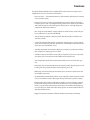
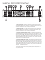
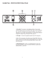
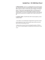
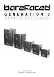
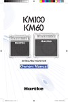
VX2515
VX2510
HA2500 2
HA2500 2
250 WATT 1 X 15” BASS COMBO
250 WATT 2 X 10” BASS COMBO
Introduction 2
Features 3
Guided Tour Front Panel Rear Panel
Setting Up and Using the VX2510 & VX2515 4-5
6-7
8-9
About Equalization 10-11
About Compression 12
Appendix A: Caster Installation 13
Appendix B: Block Diagram 14
Appendix C:
Changing the VX2510 & VX2515 Voltage 15
Specifications 16
Copyright 2005 - 2008, Samson Technologies Corp.
Printed June, 2008 v1.1
Samson Technologies Corp.
45 Gilpin Avenue
Hauppauge, New York 11788-8816
Phone: 1-800-3-SAMSON (1-800-372-6766)
Fax: 631-784-2201
www.samsontech.com
Introduction
Congratulations on purchasing the Hartke VX2510 & VX2515 Bass Amplifier! Although this unit is designed for easy operation, we suggest you first take some
time to go through these pages so you can fully understand how we’ve implemented
a number of unique features.
The VX2510 & VX2515 combos feature tH HA2500 amplifer providing 250 watts of
power to the built-in 2-way bass speaker system. With that kind of power and Hartke’s
custom designed transducers, including 2 x 10-inch low frequency, working with a
1-inch high frequency compression driver in the VX2510 and a15-inch low frequency
drive unit plus 1-inch high frequency compression driver in the VX2515, these bass
combos are EXTREMELY loud and punchy. In addition, the VX2510 & VX2515 offer
a number of additional advanced features, including front-panel compression and
graphic equalizer LED indicators, effects send and return jacks, an effects send/return
balance knob, and a direct output with ground lift and pre or post EQ selection. The VX2510 & VX2515 are optimized for use with electric bass instruments, and the
front panel controls in both models are virtually identical. You’ll find either to be an
excellent bass amplifier for live performance use in small and medium-size venues; in
addition, the VX2510 & VX2515’s advanced pre-amp features makes it ideal for use in
recording environments.
In these pages, you’ll find a detailed description of the many features of the VX2510
& VX2515 bass amplifier, as well as a guided tour through their front and rear panels,
step-by-step instructions for setting up and using each product, detailed discussions
about equalization and compression, and full specifications. You’ll also find a warranty
card enclosed—please don’t forget to fill it out and mail it so that you can receive
online technical support and so we can send you updated information about these
and other Hartke and Samson products in the future.
SPECIAL NOTE: Should your unit ever require servicing, a Return Authorization number (RA) is necessary. Without this number, the unit will not be accepted. Please call
Samson Technologies at (516) 932-1062 for a Return Authorization number prior to
shipping your unit. Please retain the original packing material and, if possible, return
the unit in its original carton and packing materials.
Features
The Hartke VX2510 & VX2515 bass amplifier offers all the newest concepts in bass
amplification. Here are some of its main features:
• Power to spare — The VX2510 & VX2515, a full 250 watts delivered to its internal
4 ohm speaker system.
• Internal, 2-way bass speaker system including two custom design 10-inch low
frequency drivers, plus 1-inch high frequency compression driver in the VX2510
and custom design 15-inch low frequency drivers, plus 1-inch high frequency
compression driver in the VX2515.
• Our unique Transient Attack® circuitry which ensures that every nuance of your
bass performance is reproduced faithfully.
• Two Pre-Amp input knobs, allowing custom blending of tube emulation and
solid state sounds.
• Ten bands of high-quality graphic equalization, allowing you to create a broad
range of tonal colors for your bass instrument. A dedicated in/out button allows
you to preset an equalization curve.
• Two fully adjustable contour knobs (high pass and low pass), which provide further control over shaping your bass sound.
• A built-in compressor which not only adds real “punch” to your bass sound, but
also allows you to smooth out volume differences between notes.
• Two independent inputs that accommodate both passive and active bass guitars.
• Protection relay circuitry that protects connected speakers from dangerous overloading and also prevents “thumps” when powering on or off.
• Effect loop send and return jacks that allow you to connect to professional outboard effects processors.
• An effect Balance knob which enables you to adjust the relative amount of Send
(“dry”) versus Return (“wet”) effect signal being routed to the speaker outputs.
• Electronically balanced direct output that provides a means of routing signal to
professional mixing consoles in both live performance and recording environments. A ground loop switch helps prevent hum or buzz from entering the signal, and a pre/post switch allows the direct signal to be derived either before or
after the amp EQ section.
• Rugged construction makes the VX2510 & VX2515 eminently road-worthy.
Guided Tour - VX2510 & VX2515 Front Panel
1
4
HA2500 2
1. Passive Input jack - If your bass guitar has passive circuitry, connect it
to the Model 2500 here. This standard, 1/4” unbalanced jack provides a high
impedance (100 k Ohms) input sensitivity of 20 millivolts.
2. Active Input jack - If your bass guitar has active circuitry,* connect it to
the Model 2500 here. This standard, 1/4” unbalanced jack provides a high
impedance (100 k Ohms) input sensitivity of 60 millivolts.
3. Pre-Amp A (Tube Emulation) control - This determines the amount of
preamplification being provided by special circuitry which delivers the sound
of a classic tube amplifier. Note that when both Pre-Amp knobs are used at
equal settings, the amplifier will be twice as loud as when only one is used. Avoid setting both Pre-Amp knobs on maximum (“10”), since the result will
almost always be undesirable distortion.
4. Pre-Amp B (Solid State) control - This determines the amount of preamplification being provided by special circuitry which delivers the sound of a
solid state amplifier. Note that when both Pre-Amp knobs are used at equal
settings, the amplifier will be twice as loud as when only one is used. Avoid
setting both Pre-Amp knobs on maximum (“10”), since the result will almost
always be undesirable distortion.
* Bass guitars that have active circuitry normally require a battery for the circuitry to be functional.
Guided Tour - VX2510 & VX2515 Front Panel
5. Compression control - This determines the amount of compression (peak
signal reduction) by simultaneously adjusting both threshold and compression ratio (which ranges from 2:1 to infinity [limiting]). At the fully counterclockwise “Off” position, the circuitry is bypassed and no compression is
applied (the knob clicks when set to the “Off” position). As the knob is raised
clockwise (at settings from “1” to “∞”) increasing amounts of compression are
applied. For more information, see the “About Compression” section on page
12 of this manual.
6. Graphic Equalizer In/Out switch - When pressed in (the “In” position), the
Model 2500’s graphic equalizer circuitry (as described in #7 below) is operational. When pressed out (the “Out” position), it is bypassed. The provision of
this switch allows you to set up a custom equalization curve (an equalization
“preset”) with the graphic EQ sliders, which can then be activated with the
press of a single button.
7. Graphic Equalizer - These sliders allow you to “draw” the tonal response of
the system by adding 15 dB of boost or attenuation to ten different narrowband frequency areas (30 Hz, 64 Hz, 125 Hz, 250 Hz, 500 Hz, 1 kHz, 2 kHz, 3
kHz, 5 kHz, and 8 kHz), affecting the main output signal of the Model 2500. When a slider is at its center detented (“0”) position, the selected frequency
area is unaffected (it is said to be flat). When a slider is moved up (above
the “0” position, towards the “+15” position), the selected frequency area
is boosted, and when it is moved down (below the “0” position, towards the
“-15” position), the selected frequency area is attenuated. For more information, see the “About Equalization” section on pages 10 - 11 of this manual.
8. Contour Low Pass control - This acts as a broad-band low frequency equalizer, providing 18 dB of boost or attenuation at 100 Hz. You should
generally adjust this control (and the Contour High Pass control, described
in #9 below) prior to “fine-tuning” the system with the graphic equalizer (as
described in #7 above). For more information, see the “About Equalization” section on pages 10 - 11 of this manual.
9. Contour High Pass control - This acts as a broad-band high frequency
equalizer, providing 18 dB of boost or attenuation at 10 kHz. You should generally adjust this control (and the Contour Low Pass control, described
in #8 above) prior to “fine-tuning” the system with the graphic equalizer (as
described in #7 above). For more information, see the “About Equalization”
section on pages 10 - 11 of this manual.
10. Master Volume control - This is the overall volume control. For best
signal-to-noise ratio, keep the output of your bass at or near maximum and
adjust the amp’s Master Volume to the desired level.
11. Power LED - Lights whenever the Model 2500 is powered on.
12. Power switch - Use this to power the Model 2500 on or off.
Guided Tour - VX2510 & VX2515 Rear Panel
1
3
5
4
6
2
1. Fuse sled - This contains a fuse holder and shows the currently
selected voltage rating for your Model 2500. Make sure the voltage rating is correctly set before powering up the amplifier! Fuse ratings are
10 amp for 115 vac and 6.2 amp for 230 vac. For information on how to
change the voltage rating, see Appendix B on page 14.
2. AC input - Connect the supplied standard 3-pin “IEC” plug here.
3. Fan - The fan provides vital cooling to your Model 2500. Make sure
that it is kept free of all obstructions and that cool, fresh air is accessible
at all times. Also, try to ensure that the Model 2500 is used in a dustfree environment.
4. Effect Return jack - Use this 1/4” unbalanced jack to return low
impedance (600 ohm) signal to the Model 2500 from a professional
outboard effects processor.*
Guided Tour - VX 2500 Rear Panel
5. Effect Send jack - Use this 1/4” unbalanced jack to send low impedance (100 ohm) signal from the Model 2500 to a professional outboard
effects processor such as a reverb, echo, chorus, flanger, or harmonizer
device.* Output level is approximately 0 dB to +4 dB and is post-EQ
and post-compression but unaffected by the setting of the Master
Volume control. You can also use the Effect Send jack to route signal to
an external mixing console or amplifier with an input sensitivity of +4
dB.
6. Speaker outputs - The VX2510 & VX2515 internal speaker system is
connected here.
* In-line effects (such as footpedals) intended for low signal levels should
be placed between the bass and the amplifier Input and not connected
with the Effect Send and Return jacks.
** Note that the settings of the ten-band graphic equalizer will affect a
“Post” Direct Out signal regardless of the position of the front panel In/Out
switch.
Setting Up and Using the VX2510 & VX2515
Setting up your Hartke Systems VX2515/VX2510 Bass Amplifier is a simple procedure
which takes only a few minutes:
1. Remove all packing materials (save them in case of need for future service) and
decide where the amplifier is to be physically placed. To avoid potential overheating
problems, be sure that the rear panel is unobstructed and that there is good ventilation around the entire unit, particularly behind the rear-panel fan. 2. Locate the included casters, which are packed separately in the shipping carton,
and follow the installation instructions outlined in Appendix A on page 13 of this
manual.
WARNING: Hartke amplifiers can deliver very high power levels. Driven to full
power, they can damage connected loudspeakers, regardless of brand, size, or
configuration. Care should be taken not to strain connected loudspeakers as this
can cause permanent damage and will degrade the performance of the entire
system. If you see connected loudspeakers moving excessively, turn your system down immediately or use the equalization and/or compression controls to
reduce the amount of subharmonic (extremely low frequency) signal.
3. Next, connect the 3-pin AC plug into any grounded AC socket. Don’t turn the
amplifier on just yet, though.
INPUT
PASSIVE
ACTIVE
4. Use a standard music instrument cable to connect your bass to the appropriate Input jack on the front panel (if your bass has active circuitry,* connect it to the
“Active” input; if not, connect it to the “Passive” input). On the front panel of the
Model VX2515/VX2510, set the Master volume control to “0” (fully counterclockwise)
and set both Pre-Amp A (Tube) and B (Solid State) knobs to “5” (the twelve o’clock
position). Set the Compression knob to its “Off” position (fully counterclockwise—
you’ll hear a click) and set both Contour knobs to their center detented “0” position. Finally, set the graphic equalizer In/Out switch to its “Out” position.
5. Press the front panel Power switch in order to turn on the amplifier. After
approximately three seconds, you’ll hear a click, indicating that the relay protection
circuitry has completed cycling and that power to the system has been provided.
o
POWER
6. Set the output of your bass to maximum and then, while playing, slowly turn the
Master volume control up until the desired level is achieved. If you hear distortion
even at low amplifier Master volume settings, back off the output of your bass (or
check for a faulty cable).
* Bass guitars that have active circuitry normally require a battery for the circuitry to
be functional.
Setting Up and Using The VX2510 & VX2515
7. Experiment with altering the balance of the two Pre-Amp knobs, listening to
the effect each has on the overall sound. Depending upon the specific instrument you are using and your personal taste, you may prefer the sound of one
over the other, or you may prefer a particular blend of the two. Note that, when
both are used at equal settings, the amplifier will be twice as loud as when only
one is used. In step #4 on the previous page, we recommended that you begin
with both knobs at their midway “5” setting, but the two Pre-Amp knobs can in
fact be set to any blend you like. However, you will usually want to avoid setting
both to their maximum “10” position since this setting will almost always result in
undesirable distortion.
8. When you have settled on a Pre-Amp balance, the next step is to adjust the
two Contour (bass and treble equalizer) controls to taste. For more information,
see the “About Equalization” section on page 13 of this manual. When you get
a great setting that complements your instrument and playing style, it’s a good
idea to write it down for future use.
PRE AMP
A
10. Now try out the Model VX2515/VX2510 compression circuitry. Activate it
by turning the Compression knob clockwise from its “Off” position (you’ll hear
a click when it is activated). As you turn the knob clockwise, the input signal
from your bass becomes more and more severely compressed—you’ll hear peak
signals (such as string slaps and pulls) begin to sound increasingly “squashed,”
relative to the lower-level signals produced by standard playing. The result
will be a decreased dynamic range but an overall leveling of signal throughout
the full pitch range of your instrument. For more information, see the “About
Compression” section on page 15. In the Model 2500, the Compression LED will
light steadily green when no compression is being applied, will go out whenever
small amounts of compression are being applied and will flash or light steadily
red when limiting (severe compression) is being applied.
11. If you’re using an external signal processor, turn your Hartke amplifier off
momentarily and then connect a standard audio cable between the Effect Send
jack and your effects processor input and another standard audio cable between
the Effect Return jack and your effects processor output (if required, multiple
effects processors can be daisy-chained together, output to input). Then turn the
amp back on and play your bass while adjusting the controls of your outboard
effects processor(s). For best results, set both the input and output gain of all
connected effects processor(s) to 0 dB (unity gain), so that there is no increase or
decrease in level whether the effects are switched in or out.
If you have followed all the steps above and are still experiencing difficulties, call
Samson Technical Support (516-932-1062) between 9 AM and 5 PM EST.
* For more information on the use of the Hartke 2500 effect Balance control, see
page 10 in this manual.
6
7
1
5
4
3
6
7
8 2
2
0
10
9
TUBE
1
8
0
10
9
SOLID STATE
CONTOUR
GRAPHIC EQUALIZER
30Hz
64Hz
125Hz
5
+15
IN
3
0 250Hz
3
0
500Hz
1KHz
3
5
5
02KHz
3
15
-18
15
+18
LOW PASS
3KHz
5KHz
8KHz
5
+15
+12
+9
+6
+3
+2
10
10 10
15
-18
OUT
9. Next, experiment with the Model VX2515/VX2510 graphic equalizer. Begin
by setting each of the ten sliders to their flat “0” center detented position. Then
press in the In/Out switch (to its “In” position) so that the graphic equalizer is activated. Finally, move each slider in turn as you play your bass. For more information, see the “About Equalization” section on page 13 of this manual. Again, when
you get a graphic equalization setting that complements your instrument and
playing style, it’s a good idea to write it down for future use.
B
5
4
3
15
+18
-2
-3
-6
-9
-12
-15
HIGH PASS
-15
30Hz
64Hz
125Hz
250Hz
30Hz
64Hz
125Hz
250Hz
500Hz
1KHz
2KHz
3KHz
5KHz
8KHz
3KHz
5KHz
8KHz
GRAPHIC EQUALIZER
500Hz
1KHz
2KHz
+15
+12
+9
+6
+3
+2
+15
IN
0
-2
-3
-6
-9
-12
-15
OUT
-15
30Hz
64Hz
125Hz
250Hz
30Hz
64Hz
125Hz
250Hz
500Hz
1KHz
2KHz
3KHz
5KHz
8KHz
3KHz
5KHz
8KHz
GRAPHIC EQUALIZER
500Hz
1KHz
2KHz
+15
+12
+9
+6
+3
+2
+15
IN
0
OUT
4
3
-15
30Hz
64Hz
125Hz
2
1
250Hz
0
5
6
7
8
500Hz
1KHz
∞
-2
-3
-6
-9
-12
-15
9
2KHz
COMPRESSION
Model 2500 Effect
Send/Return jacks
3KHz
5KHz
8KHz
About Equalization
The Hartke Systems Model 2500 Bass Amplifier gives you enormous control over
shaping the sound of your bass, using a process called equalization. To understand
how this works, it’s important to know that every naturally occurring sound consists
of a broad range of pitches, or frequencies, combined together in a unique way. This
blend is what gives every sound its distinctive tonal color. EQ controls allow you
to alter a sound by boosting or attenuating specific frequency areas—they operate
much like the bass and treble controls on your hi-fi amp, but with much greater precision. The Model 2500 provides you with two different means for equalizing your bass
sound:
CONTOUR
5
3
0
3
5
5
3
0
3
5
10
10 10
15
-18
15
+18
15
-18
LOW PASS
15
+18
HIGH PASS
GRAPHIC EQUALIZER
30Hz
64Hz
+15
125Hz
250Hz
500Hz
1KHz
2KHz
3KHz
Contour controls
5KHz
8KHz
+15
+12
+9
+6
+3
+2
IN
0
-2
-3
-6
-9
-12
-15
OUT
-15
30Hz
64Hz
125Hz
250Hz
30Hz
64Hz
125Hz
250Hz
500Hz
1KHz
2KHz
3KHz
5KHz
8KHz
3KHz
5KHz
8KHz
GRAPHIC EQUALIZER
500Hz
1KHz
2KHz
+15
+12
+9
+6
+3
+2
+15
IN
0
-2
-3
-6
-9
-12
-15
OUT
-15
30Hz
64Hz
125Hz
250Hz
500Hz
1KHz
2KHz
3KHz
5KHz
8KHz
3KHz
5KHz
8KHz
Graphic equalizer
GRAPHIC EQUALIZER
30Hz
64Hz
125Hz
250Hz
500Hz
1KHz
2KHz
•
Low Pass and High Pass Contour controls provide 18 dB of cut or boost in
two broad frequency bands.
•
Graphic Equalizer provides 15 dB of cut or boost in ten narrow frequency
A
bands.
Normally, you will adjust the two Contour controls before “fine-tuning” your EQ with
the Graphic Equalizer. The Low Pass Contour control affects a broad band of frequencies with 100 Hz as the center point; similarly, the High Pass Contour control affects a
broad band of frequencies with 10 kHz as the center point. When either is in its center detented position (“0”), it is having no effect. When it is moved right of center, the
particular frequency area is being boosted; when it is moved left of center, the frequency area is being cut (“attenuated”). Because there is very little bass guitar energy
at 10 kHz, the High Pass Contour control should be thought of as your overall “noise”
control—turning it down (to the left of the “0” position) will help to eradicate hiss and
buzz while having very little effect on the bass guitar signal. Similarly, the Low Pass
Contour control, when set left of 0, can be used to eliminate rumble and “woofiness.”
The ten-band graphic equalizer provides ten sliders, each corresponding to a single
narrow frequency band (at 30 Hz, 64 Hz, 125 Hz, 250 Hz, 500 Hz, 1 kHz, 2 kHz, 3 kHz, 5
kHz, and 8 kHz). This allows you to “draw” the desired tonal response of your system. When a slider is in its center detented position (“0”), it is having no effect. When it is
moved above center (towards “+15”), the particular frequency area is being boosted;
when it is moved below center (towards “-15”), the frequency area is being attenuated. We carefully selected these frequency areas because they have maximum
impact on bass signals. For example, the lowest slider (30 Hz) affects the very lowest
audible frequencies (in fact, most humans cannot hear below 20 Hz), while the highest four sliders (2, 3, 5, and 8 kHz) affects the “twang” of a bass string.
+15
+12
+9
+6
+3
+2
+15
IN
0
-2
-3
-6
-9
-12
-15
OUT
-15
30Hz
64Hz
125Hz
250Hz
500Hz
1KHz
2KHz
3KHz
5KHz
8KHz
WARNING: Use caution when raising the 30 Hz slider above 0 if you are operating
at high volume levels (especially if Compression is not being used) since this can
place undue stress on connected loudspeakers.
10
About Equalization
To find out how each graphic equalizer slider affects the sound of your particular
bass, start with all ten bands flat (that is, all ten sliders at their detented “0” center
position). Then, one by one, raise and lower each slider, listening carefully to the
effect of each. If you don’t specifically need to utilize the ten-band graphic equalizer, bypass it by setting the In/Out switch to its “Out” position. Alternatively, you can
preset a custom graphic equalization curve (for example, for a feature solo) and activate it simply by pressing the switch when needed. Note that turning all EQ controls up the same amount will have virtually the same effect as simply turning up
the Master Volume; conversely, turning them all down the same amount will have
virtually the same effect as turning down the Master Volume. Both approaches are
pointless (after all, that’s why we gave you a Master Volume control!)
In many instances, the best way to deal with equalization is to think in terms of
which frequency areas you need to attenuate, as opposed to which ones you need
to boost. Be aware that boosting a frequency area also has the effect of boosting
the overall signal; specifically, too much low frequency EQ boost can actually cause
overload distortion or even harm a connected speaker, though the Model 2500’s
compression circuitry—if on—will act to some extent to prevent this from occurring. In general, if you’re going to apply a fair amount of low frequency EQ boost,
it’s a good idea to keep Compression on, if only to protect your speakers from
potential damage.
The specific EQ you will apply to your bass signal is very much dependent upon
your particular instrument and personal taste and playing style. However, here are
a few general suggestions: •
For that super-deep reggae or Motown sound, boost low frequencies
slightly while attenuating the highest ones (leave mid-range frequencies
flat or slightly attenuated), as shown in the illustration on the right.
•
T o remove boxiness and make your instrument sound more “hi-fi,” try
attenuating mid-range frequencies while leaving low and high frequency
settings flat, as shown in the illustration on the right.
GRAPHIC EQUALIZER
30Hz
64Hz
125Hz
250Hz
500Hz
1KHz
2KHz
3KHz
5KHz
8KHz
+15
+12
+9
+6
+3
+2
+15
IN
0
-2
-3
-6
-9
-12
-15
OUT
-15
•
F or a twangy, cutting sound, try boosting the high and high mid-range
frequencies, as shown in the illustration on the right (putting new roundwound strings on your bass will help a lot also!)
30Hz
64Hz
125Hz
250Hz
30Hz
64Hz
125Hz
250Hz
500Hz
1KHz
2KHz
3KHz
5KHz
8KHz
3KHz
5KHz
8KHz
GRAPHIC EQUALIZER
500Hz
1KHz
2KHz
+15
+12
+9
+6
+3
+2
+15
IN
•
henever you get a really good EQ setting for a particular instrument or
W
song, write it down (you’d be amazed how easy it is to forget these things!).
Finally, as you experiment with the EQ controls of the Model 2500, don’t forget that
your bass also provides EQ controls in the form of its tonal settings—this can be
particularly effective in instruments that have active circuitry. Also, try various EQ
settings with different Pre-Amp blends and with and without Compression. For
more information, see the “About Compression” section on the following page.
0
-2
-3
-6
-9
-12
-15
OUT
-15
30Hz
64Hz
125Hz
250Hz
30Hz
64Hz
125Hz
250Hz
1KHz
2KHz
3KHz
5KHz
8KHz
3KHz
5KHz
8KHz
GRAPHIC EQUALIZER
500Hz
1KHz
2KHz
+15
+12
+9
+6
+3
+2
+15
IN
0
-2
-3
-6
-9
-12
-15
OUT
-15
30Hz
11
500Hz
64Hz
125Hz
250Hz
500Hz
1KHz
2KHz
3KHz
5KHz
8KHz
About Compression
The dynamic range of a sound is the difference between its loudest and softest
points. For example, as you play your bass, you’ll probably find that some notes
(for example, notes played on the upper frets of the lowest string) are considerably
louder than others. The function of the Compression circuitry in the Model 2500 Bass
Amplifier is to reduce overall dynamic range by automatically reducing the level of
the loudest sounds you play so that they are closer in level to softer ones—the end
result is that the sound “evens out” and all notes played have pretty much the same
level. The front-panel Compression control determines the amount of compression (peak
signal reduction) by simultaneously adjusting both threshold and compression ratio
(which ranges from 2:1 to infinity [limiting]). At the fully counterclockwise “Off” position, the circuitry is bypassed and no compression is applied (the knob clicks when
set to the “Off” position). As the knob is raised clockwise (at settings from “1” to “∞”)
increasing amounts of compression is applied. At the highest settings, loud sounds
will not just be compressed, but limited, where the output remains virtually constant
regardless of input. 4
3
5
6
2
1
7
8
0
∞
9
COMPRESSION
VX2510 & VX2515
Compression control and
LED
The Model 2500 provides a front-panel Compression LED which acts as a useful visual
indicator of the continuous activity of the compression circuitry. When lit steadily
green (for example, when the Compression knob is set to “Off”), no compression is
being applied. When unlit, compression is being applied to the incoming signal at a
ratio of approximately 2:1. When flashing red, the compression ratio is approaching infinity (limiting is being applied). When lit steadily red, the signal is being
limited. This LED “follows” the incoming signal, changing continuously as different
amounts of compression and/or limiting are being applied.
Compression has three main uses. First, as just described, it “evens” out the notes
played by your bass so that they all appear at virtually equal level. Second, it adds
“punch” to a sound; since all levels are nearly the same, you can play with greater
force without worrying about the loudest notes distorting. Finally, it serves to protect
your loudspeakers from damage as a result of brief (transient) high output levels, as
might be caused by finger-popping or other performance techniques.
Whether or not you need to use compression with your Model 2500 will be a matter
of personal taste and playing style—experiment and see if you like the effect. If you
usually play at low volume levels, you’ll find that, even with the Compression knob
turned up, the compression circuitry may have no audible effect, so it might as well
be off. In general, if you don’t need compression, leave it off.
12
Appendix A: CASTER INSTALLATION
•
Locate one caster and four each of the supplied screws
and lock washers.
•
Hold the caster in place and hand start the screws. Be
careful to ensure that the screws are on the proper
thread chase. DO NOT PUSH TEE NUT INTO ENCLOSURE. •
Use a screw driver to tighten the four screws. Be careful
not to over tighten the screws.
•
Repeat the steps above for the remaining three casters.
13
Appendix B: Block Diagram
Model 2500
14
Appendix C: Changing the VX2510 & VX2515 Voltage
15
Specifications
Input Sensitivity
Passive Input
Active Input
100 k Ohms 20 mv.
100 k Ohms 60 mv.
Rated Output Power Total Harmonic Distortion
250 watts @ 4 ohms
less than .5%
Signal To Noise Ratio
approx. 78 dBm
Equalizer
Contour Low Pass
Contour High Pass
Ten-Band Graphic
±18 dB @ 100 Hz
±18 dB @ 10 kHz
±15 dB, center detented
@ 30 Hz, 64 Hz, 125 Hz, 250 Hz, 500 Hz, 1 kHz, 2 kHz, 3 kHz, 5 kHz, 8 kHz
Compression Ratio
2:1 to infinity
Send Output Level
0 dBM
Return Input Level
VX2510 Speaker System Impedance (Ohms)
Low Frequency Drivers
High Frequency Driver
0 dBM
4 Ohms Impedance
2-10" Special Design 8 ohm, 150 watt Speakers,
1” Throat Compression Driver
VX2515 Speaker System Impedance (Ohms)
Low Frequency Drivers
High Frequency Driver
4 Ohms Impedance
1-15" Special Design 4 ohm, 250 watt Speakers,
1” Throat Compression Driver
VX2510 Weight
Dimensions
75 lbs. (34 kg)
Height:29." (73.3 cm)
Width: 26.5" (67.6 cm)
Depth: 17.25" (43.5 cm)
VX2515 Weight
Dimensions
76.5 lbs. (34.8 kg)
Height: 30.75" (78 cm)
Width: 26.5" (67.6 cm)
Depth: 17.25" (43.5 cm)
16
Hartke
45 Gilpin Avenue
Hauppauge, New York 11788-8816
Phone: 1-800-3-SAMSON (1-800-372-6766)
Fax: 631-784-2201
www.hartke.com