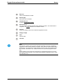
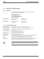
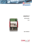
1
User Manual M3000® Control System QAIO 16/4 Analog I/O Extension Module QAIO NOTES ON THIS MANUAL This M3000® module is commercialized by Moog and Berghof Automationstechnik together. The main part of this manual was created by Berghof Automationstechnik GmbH and was inserted unchanged. Therefore, it is possible that some terms in this manual do not correspond to the terms used in the other M3000® manuals. COPYRIGHT © 2003 Moog GmbH Hanns-Klemm-Straße 28 71034 Böblingen (Germany) Telefon: +49 7031 622-0 Telefax: +49 7031 622-100 E-Mail: [email protected] [email protected] Internet: http://www.moog.de http://www.moog.com/M3000 All Rights Reserved. No part of this manual may be reproduced in any form (print, photocopies, microfilm, or by any other means) or edited, duplicated, or distributed with electronic systems without prior written consent from Moog. Offenders will be held liable for the payment of damages. RESERVATION OF CHANGES AND VALIDITY Subject to changes without prior notice. The information included in this manual is valid at the release date of this manual. See footer for version number and release date of this manual. EXCLUSION OF LIABILITY This manual was prepared with great care and the contents reflect the authors’ best knowledge. However, the possibility of error remains and improvements are possible. Please feel free to submit any comments regarding errors or incomplete information to Moog. Moog does not offer any guarantee that the contents conform to applicable legal regulations, nor does Moog accept any liability for incorrect or incomplete information and the consequences thereof. TRADEMARKS Moog and Moog Authentic Repair are registered trademarks of Moog Inc. and its subsidiaries. DIN EN ISO 9001 Our quality standard is according to DIN EN ISO 9001. A Moog • User Manual QAIO • (Version 1.0; 09/03) All product designations mentioned in this manual are trademarks of the respective manufacturers. The absence of the trademark symbols ® or ™ does not indicate that the name is free from trademark protection. QAIO 16/4-V QAIO 16/4-A Analog I/O expansion modules V.1.1 User Handbook Copyright © Berghof Automationstechnik GmbH Reproduction and duplication of this document and utilisation and communication of its content is prohibited, unless with our express permission. All rights reserved. Damages will be payable in case of infringement. Disclaimer The content of this publication was checked for compliance with the hardware and software described. However, discrepancies may arise, therefore no liability is assumed regarding complete compliance. The information in this document will be checked regularly and all necessary corrections will be included in subsequent editions. Suggestions for improvements are always welcome. Subject to technical changes. Trademark CANtrol® // is a registered trademark of Berghof Automationstechnik GmbH General Information on this Manual Content: This manual describes the CANtrol module QAIO 16/4-V and QAIO 16/4-A and its modifications. The product-related information contained herein was up to date at the time of publication of this manual. Completeness: This manual is complete only in conjunction with the user manual entitled ‘Introduction to CANtrol Automation System’ and the product-related hardware or software user manuals required for the particular application. Standards: The CANtrol automation system, its components and its use are based on International Standard IEC 61131 Parts 1 to 4 (EN 61131 Parts 1 to 3 and Supplementary Sheet 1). Supplementary Sheet 1 of EN 61131 (IEC 61131-4) entitled ‘User Guidelines’ is of particular importance for the user. Order numbers: Please see the relevant product overview in the ‘Introduction to CANtrol Automation System’ manual for a list of available products and their order numbers. Ident. No.: 2801720 You can reach us at our headquarters at: Germany: Austria: Berghof Automationstechnik GmbH Harretstr. 1 D-72800 Eningen Phone: +49 (0) 71 21 / 8 94-0 Telefax: +49 (0) 71 21 / 89 41 00 http://www.berghof-automation.de e-mail: [email protected] Berghof Elektronik und Umwelttechnik GmbH Nfg KG A-6200 Wiesing 323 Phone: +43 (0) 52 44 / 6 48 08 -0 Telefax: +43 (0) 52 44 / 6 48 08 -81 http://www.berghof.co.at e-mail: [email protected] The Berghof Automationstechnik GmbH works in accordance with DIN EN ISO 9001 Berghof Automationstechnik QAIO 16/4-x Update Version .doc Date 1.0 5-00 1.1 01.04.02 Subject First version Formal updates, company name and product name removed. 2D0172002ZD00.doc 3 QAIO 16/4-x Berghof Automationstechnik blank page 4 2D0172002ZD00.doc Berghof Automationstechnik QAIO 16/4-x Contents 1. GENERAL INSTRUCTIONS....................................................................................... 7 1.1. Hazard Categories and Indications ......................................................................................................7 1.2. Qualified users .......................................................................................................................................7 1.3. Use as Prescribed ..................................................................................................................................8 2. ANALOG I/O EXPANSION MODULE ........................................................................ 9 2.1. Overview .................................................................................................................................................9 2.2. Technical data ......................................................................................................................................10 2.3. Block circuit diagram...........................................................................................................................12 2.4. Module diagram and connection assignment ...................................................................................13 2.5. Indicators, diagnostics ........................................................................................................................14 2.6. Shielding and measurement cabling..................................................................................................15 2.7. Operation of the module......................................................................................................................16 2.7.1. Fault currents .............................................................................................................................17 2.7.2. Commissioning ..........................................................................................................................17 2.7.3. Initialisation and module identification .......................................................................................17 2.7.4. Measuring ..................................................................................................................................18 2.7.5. Sensor failure .............................................................................................................................18 2.7.6. Connection of sensors/actuators ...............................................................................................19 2.8. Analog I/O channels.............................................................................................................................20 2.8.1. Analog input channels................................................................................................................20 Voltage input (basic circuit diagram)..........................................................................................20 2.8.2. Sensor connection, examples....................................................................................................21 Floating sensors.........................................................................................................................21 Potential-afflicted sensors with auxiliary power connection.......................................................21 Sensor connection using internal module reference voltage.....................................................21 2.8.3. Analog output channels .............................................................................................................22 Voltage output (basic circuit diagram) .......................................................................................22 2.9. .doc Reference voltage source....................................................................................................................23 2D0172002ZD00.doc 5 QAIO 16/4-x Berghof Automationstechnik 3. ANNEX ......................................................................................................................25 3.1. Environmental Protection....................................................................................................................25 3.1.1. Emission.....................................................................................................................................25 3.1.2. Disposal......................................................................................................................................25 3.2. Maintenance/Upkeep............................................................................................................................25 3.3. Repairs/Service.....................................................................................................................................25 3.3.1. Warranty.....................................................................................................................................25 3.4. Nameplate..............................................................................................................................................26 3.5. Addresses and Bibliography...............................................................................................................28 3.5.1. Addresses ..................................................................................................................................28 3.5.2. Standards/Bibliography ..............................................................................................................28 6 2D0172002ZD00.doc Berghof Automationstechnik Instructions 1. General Instructions 1.1. Hazard Categories and Indications The indications described below are used in connection with safety instructions you will need to observe for your own personal safety and the avoidance of damage to property. These instructions are emphasised by bordering and/or shading and a bold-printed indication, their meaning being as follows: DANGER ! means that death, severe physical injury or substantial damage to property will occur on failure to take the appropriate precautions. Warning ! means that death, severe physical injury or substantial damage to property may occur on failure to take the appropriate precautions. Caution means that minor physical injury or damage to property may occur on failure to take the appropriate precautions. Note: provides important information on the product or refers to a section of the documentation which is to be particularly noted. 1.2. Qualified users Qualified users within the meaning of the safety instructions in this documentation are trained specialists who are authorised to commission, earth and mark equipment, systems and circuits in accordance with safety engineering standards and who as project planners and designers are familiar with the safety concepts of automation engineering. 2VF100054FE01.doc 2D0172002ZD00.DOC 7 Instructions 1.3. Berghof Automationstechnik Use as Prescribed This is a modular automation system based on the CANbus, intended for industrial control applications within the medium to high performance range. The automation system is designed for use within Overvoltage Category I (IEC 364-4-443) for the controlling and regulating of machinery and industrial processes in low-voltage installations in which the rated supply voltage does not exceed 1,000 VAC (50/60 Hz) or 1,500 VDC. Qualified project planning and design, proper transport, storage, installation, use and careful maintenance are essential to the flawless and safe operation of the automation system. The automation system may only be used within the scope of the data and applications specified in the present documentation and associated user manuals. The automation system is to be used only as follows: as prescribed, in technically flawless condition, without arbitrary or unauthorised changes and exclusively by qualified users The regulations of the German professional and trade associations, the German technical supervisory board (TÜV), the VDE (Association of German electricians) or other corresponding national bodies are to be observed. Safety-oriented (fail-safe) systems Particular measures are required in connection with the use of SPC in safetyoriented systems. If an SPC is to be used in a safety-oriented system, the user ought to seek the full advice of the SPC manufacturer in addition to observing any standards or guidelines on safety installations which may be available. Warning ! 8 As with any electronic control system, the failure of particular components may result in uncontrolled and/or unpredictable operation. All types of failure and the associated fuse systems are to be taken into account at system level. The advice of the SPC manufacturer should be sought if necessary 2D0172002ZD00.DOC 2VF100054FE01 Berghof Automationstechnik Analog I/O expansion module 2. Analog I/O expansion module 2.1. Overview Order number For replacement parts, the order/item no. can be found on the module’s nameplate. Function The module is used to expand the analog I/O level of Cell Controllers. The modules are connected by direct E-bus coupling and is available with voltage or current inputs. Features Common characteristics 4 analog output channels in the form of voltage outputs, +/-10 V (GND sensing) resolution 11 bit + sign 1 reference voltage output +10 V Low space requirements and low mounting depth. The modules with voltage or current inputs also have the following features: Module with voltage inputs: 16 analog voltage input channels, suitable for connecting active and passive resistors. voltage rating, differential +/-10 V measured value resolution 11 bit + sign Module with current inputs: Lieferumfang Supplied with the module package is: 2VF100051FE01.doc 16 analog current input channels, current rating, 0... 20 mA measured value resolution 11 bit + sign An analog I/O expansion module with voltage or current inputs. 2D0172002ZD00.DOC 9 Analog I/O expansion module 2.2. Berghof Automationstechnik Technical data Module data Analog I/O expansion module Dimensions w x h x d [mm] Weight Mounting Working temperature Operation and display voltage or current inputs 124 x 170 x 85.5 (modular dimension: B = 113/118.5) approx. 550 g Mounting rail NS 35/7,5 EN 50022 5°C to 50°C (no moisture condensation) 4 status LED's EMC, class of protection, insulation testing, degree of protection EMC (EN 50081-2 / EN 50082-2) Emitted interference Noise immunity Class of protection Insulation resistance Degree of protection To achieve the precision specified, the user is required to implement shielding measures. EN 50081-2, industrial sector EN 50082-2, industrial sector EN 61131-2 EN 61131-2; 500 VDC (test voltage) IP 20 Supply voltage, power consumption Module electronics power supply (supply voltage) Power consumption Electrical isolation Reverse voltage protection Connections SELV DC +24 V max. 0.3 A (EN 61131-2) on AGND earth at Ue = DC +24 V idling max. 300 mA yes, optodecoupled from E bus; no isolation between power supply and analog channels yes vertical front wiring push-on terminal strips for screw, crimp or pinch connection Reference voltage source Reference voltage Load current Precision DC +10 V permanent short-circuit protection; IKmax 25 mA max. 5 mA 0.1% Various characteristics Data format in application program Monotonicity Cross talk between channels - direct current - 50 Hz - 60 Hz Non-linearity Repeat accuracy at certain temperature after 1 hour stabilising time Integer 16 bit yes >70 dB >70 dB >70 dB < 1 LSB < 1 LSB Analog inputs Static characteristics:: Number Type Input impedance in signal range Analog input error of measurement - greatest error at 25°C - temperature coefficient Greatest error over full temperature range LSB value Max. permissible continuous overload (exceeding this causes damage) 10 voltage inputs 16 voltage ± 10 V, differential 10 M Ohm current inputs 16 current, ± 20 mA ±0.1% of maximum scale value ±0.01% of maximum scale value/°K ±0.2% of maximum scale value ±0.02% of maximum scale value/°K ± 0,2 % of maximum scale value ± 0,3 % of maximum scale value 4.883 mV 9.766 µA ± 30 V 50 mA 2D0172002ZD00.DOC 50 Ohm 2VF100051FE01.doc Berghof Automationstechnik Digital resolution Data format Digital value output under overload Exceeding permissible measuring range: Falling below permissible measuring range: Common mode characteristics: - common mode rejection Dynamic characteristics: Max. system input transfer time per channel (TAID+TAIT) Sampling interval per channel Sampling repetition time per channel Input filter characteristic - order - transfer frequency General characteristics: Conversion method Protection devices Insulation test voltage between analog converter and E bus Analog I/O expansion module 11 bit + sign 16 bit, integer + 32752 (+9,995 V) - 32768 (-10,000 V) ³ 70 dB <1ms see documentation on function blocks CP1131 or CPC++ 1 µs >1 ms see documentation on function blocks CP1131 or CPC++ 1st order approx. 10 kHz successive approximation; no error codes diodes DC 500 V Analog outputs Static characteristics: Output type Output impedance in signal range Analog output error: - greatest error at 25°C - temperature coefficient Greatest error over full temperature range Digital resolution Value of least significant bit (LSB) Dynamic characteristics Overall system output transfer time per channel (TAQD + TAQT) Transient time when alternating over the full range Overshoot General characteristics Type of protection devices Insulation test voltage between analog converter and E bus Permissible load types Permissible capacitive load Output response for power supply connecting/disconnecting processes.. Various characteristics Output ripple Output current Common mode range 2VF100051FE01.doc 4 x voltage (U), floating; ±10 V < 0.5 Ohm ±0.15% of maximum scale value ±0.01% of maximum scale value/°K ±0.3% of maximum scale value 11 bit + sign 4.883 mV <1 ms <1 ms typically 0.5%, load-dependent permanently short-circuit proof; IKmax = 25 mA, supply polarity-reversal-protected DC 500 V R, (C) <1000 pF typical spike: U = 0.1 V; t <10 ms Behaviour is strongly dependent on the connected load < 1 LSB max. 5 mA +/- 2 V 2D0172002ZD00.DOC 11 Analog I/O expansion module 2.3. Berghof Automationstechnik Block circuit diagram 2VF100062DG01.cdr 12 2D0172002ZD00.DOC 2VF100051FE01.doc Berghof Automationstechnik 2.4. Analog I/O expansion module Module diagram and connection assignment 2VF100028DG03.cdr 2VF100051FE01.doc 2D0172002ZD00.DOC 13 Analog I/O expansion module 2.5. Berghof Automationstechnik Indicators, diagnostics Operational status The current state of voltage supplies and module functions is indicated by 4 status LEDs located on the module cover. LED- status I/O assignment 14 Function L+ ON Module electronics supply working correctly (supply voltage) ± 15 V ON Analog unit supply working correctly + 5 V OUT ON Module is connected to Cell Controller (E bus on voltage). OUT_ENA ON ‘ENABLE’ analog outputs The print on the module covers shows the assignment of the analog I/O channels, reference outputs and incoming supply to the connection terminals. 2D0172002ZD00.DOC 2VF100051FE01.doc Berghof Automationstechnik 2.6. Analog I/O expansion module Shielding and measurement cabling Reliable operation of higher-precision analog components with fast conversion times can only be achieved in an industrial environment with the help of corresponding shielding measures and the correct metrological cabling. The user must, in this regard, observe the interaction of all the analog components and their auxiliary power supplies throughout the entire system. Mounting the module Low-frequency interference voltages High-frequency interference voltages The module must always be mounted in shielding (metal) switch cabinets/casings. Adequate isolation of interfering components and their cabling must be ensured within the casing by means of appropriate constructive measures (e.g. separate wiring, spatial separation of components). Low-frequency interference voltages, such as the omnipresent 50 Hz network crosstalk, are cancelled out by the module’s differential measuring system in conjunction with high common-mode rejection. High-frequency and pulse interferences have to be kept away from the signal lines by means of suitable shielding measures. For this purpose, the line shields in the field (outside the casing) must be connected on both sides. The best results are always achieved when the cable shields are laid flat at the points where they enter the casing. Note: Experience shows that the environmental conditions within systems and equipment can change sporadically and unexpectedly. Even if seemingly good results can be attained in a number of cases using open wiring, we advise strongly against it. Failure to implement the measures referred to can result in lengthy error diagnostic processes and high consequential costs. Users that implement the recommendations set out in this manual in a consistent manner will not encounter problems regarding current EMC directives. CE mark 2VF100051FE01.doc When designing the module, we attached great importance to its electromagnetic compatibility. Nonetheless, a considerable proportion of the action that must be taken in order to ensure reliable operation are outside our sphere of influence. For this reason, we have opted not to affix the CE mark to this automation component. In this regard we would like to draw users’ attention to their overall responsibility when incorporating the module into their applications. 2D0172002ZD00.DOC 15 Analog I/O expansion module 2.7. Berghof Automationstechnik Operation of the module Warning ! Do not insert, apply, detach or touch connections when in operation! Destruction or malfunctioning may otherwise occur. Disconnect all incoming supplies before working on modules, including those of connected peripherals such as externally supplied sensors, programming devices, etc. The module is designed for measuring and control functions located on a common potential island. Items of equipment on differing potential levels can be connected via suitable isolation devices (insulating amplifier etc.). Note: The module electronics power supply (connection voltage +24VDC) is not electrically isolated from the analog connections on the module. The negative connection point for the incoming supply (M1) is physically connected to the analog earth connection (AGND). We recommend that all sensors/actuators be operated on this supply together with the module. Consciously arranging analog wiring with a common earth is good practice. The module is designed to cope reliably and effectively with the small differences of potential unavoidably occurring when sensors and actuators are supplied jointly through appropriate SENSE lines. Caution The module’s analog channels may be connected to different earths only within the permissible common mode range. More extensive electrical isolation is not permissible for design reasons. Non-compliance with the above will cause incorrect measurements, even on uninvolved channels, and can result in transient currents which will cause permanent damage to the module. 16 2D0172002ZD00.DOC 2VF100051FE01.doc Berghof Automationstechnik 2.7.1. Analog I/O expansion module Fault currents A large number of the conceivable incorrect assignments of analog connections can be resolved by means of circuit organisation. Nonetheless, it is not economically possible with the components available today to guarantee absolute protection against all fault currents that can be implanted from outside. Caution 2.7.2. Faulty wiring, incorrect power supply or high potential differences in the measuring circuits can cause serious damage to the module or permanently impair measuring accuracy. Commissioning All connections should be re-checked for correct wiring and polarity the supply voltage is applied. The handling of the module depends on the software environment used. For this reason, you should consult the information in the programming manuals for the CP1131 or CPC++, as appropriate. 2.7.3. Initialisation and module identification The analog expansion module is identified and initialised by the operating system of the upstream Cell Controllers. The identification characteristics stored in the module are evaluated by the Cell Controller for this purpose. No dip switch settings are required. In the case of failure of the +24 V power supply or interruption of the E bus transmission, the analog outputs are reset to 0 V (LED “OUT_ENA”). 2VF100051FE01.doc 2D0172002ZD00.DOC 17 Analog I/O expansion module 2.7.4. Berghof Automationstechnik Measuring The measurements and transfer of the data from the module to the CAN node are carried out in a cyclic manner, controlled via the API (Application Process Interface) in the operating system. No start signals have to be output for AD conversion. Execution of the measuring process depends on the software environment used. For this reason, you should consult the relevant information contained in the programming manuals for CP1131 or CPC++. Note:: The following formula applies for converting the measured data into voltage values: AD AD U = 10 V I = 20 mA 15 15 2 2 Comment: AD = the value supplied by the analog channel (in_value) When leaving the permissible measuring range, the following values are reported: Exceeding the permissible measuring range (+) Falling short of the permissible measuring range (-) + 32752 - 32768 + 9,995 V - 10,000 V Representation of the 11-bit measured value with sign in a 16-bit variable: 2VF100070DG00.cdr 2.7.5. Sensor failure In the case of sensor failure, the corresponding channel reports the value for +9.995 V to the cell controller. 18 2D0172002ZD00.DOC 2VF100051FE01.doc Berghof Automationstechnik 2.7.6. Analog I/O expansion module Connection of sensors/actuators 2VF100063DG00.cdr Note: This interface connection is ideal for floating sensors/actuators. In the case of sensors/actuators with auxiliary power, it must be ensured that the energy supply currents do not flow via the AGND lines (see sector 'Analog I/O channels by ‘Sensor connection, examples’). 2VF100051FE01.doc 2D0172002ZD00.DOC 19 Analog I/O expansion module Berghof Automationstechnik 2.8. Analog I/O channels 2.8.1. Analog input channels The analog expansion module has 16 analog, multiplexed voltage inputs. These inputs are protected by protective diodes. The input current may not, even in the case of error, exceed the value of 10 mA per channel. Input channel data Input voltage/current, rated value +/- 10 V, differential +/- 20 mA Input voltage, maximum rating +/- 12 V, Input current, maximum rating 10 mA je Kanal Common mode rejection > 70 dB / DC Diff. input resistance 20 MOhm Common mode input resistance 10 MOhm, typ. st Input filter, 1 degree t = 70 µs Conversion method successive approximation, no error codes Resolution 11 bit + sign; 1 LSB = 4,883 mV 11 bit + sign; 1 LSB = 9,766 µA voltage current Precision in temp. range 0-50°C voltage current +/- 1 LSB; +/- 0,2 % +/- 1 LSB; +/- 0,3 % Voltage input (basic circuit diagram) 2VF100064DG00.cdr 20 2D0172002ZD00.DOC 2VF100051FE01.doc Berghof Automationstechnik 2.8.2. Analog I/O expansion module Sensor connection, examples Note: The measuring line shield can, where required, be connected to SHIELD. Where better HF contact of the shields is possible at another point in the casing, there should be no additional connection to SHIELD on the module. 2VF100069DG00.cdr Floating sensors Connection via 2-pole, shielded cable (IN+/AGND). In the case of floating sensors, at least one of the measuring inputs (IN -) must be bridged to AGND The cancellation of electrical isolation brought about by the bridge is absolutely necessary as capacitive signal couplings with impermissibly high common mode voltages are already built up because of the very high impedance inputs. This leads to sporadic incorrect measurements which are difficult to detect in most cases. 2VF100066DG00.cdr Potential-afflicted sensors with auxiliary power connection Connection via 2-pole, shielded cable (IN+/IN-). Sensors with auxiliary power supply but without electrical isolation should be operated from the same power supply source as the module. The sensor is connected to the two measuring inputs IN+ and IN- in the required polarity. The AGND connection of the module remains open. It is to be ensured that the potential equalisation via the common supply and sensors actually occurs. 2VF100067DG00.cdr Sensor connection using internal module reference voltage Connection via 3 or 4-pole shielded cable (IN+/IN-/URef/AGND). Radiometric sensors (potentiometer, bridge circuits) are treated as potential-afflicted sensors. The auxiliary power is also carried in the measuring line. If only one measuring input is needed, as in the case of the potentiometer connection, the free input must be bridged to AGND. It must be ensured that the reference voltage is not overloaded and that the current taken from the reference source can flow back again via the AGND connections. 2VF100068DG00.cdr 2VF100051FE01.doc 2D0172002ZD00.DOC 21 Analog I/O expansion module 2.8.3. Berghof Automationstechnik Analog output channels The analog expansion module QAIO 16/4-V has 4 analog voltage outputs. The outputs are permanently protected against short-circuiting, at a maximum short-circuit current of 25 mA. For each output, the connection points are also provided for the analog ground (AGND) and the common earth (REF) besides the signal connections (OUT). This means that earth shifts can be compensated for as long as the condition |UREF | <2 V is complied with for each output. The SENSE connectors are connected directly to the earth of the associated actuator. Note: The SENSE line cannot be used alone as the feedback. Output channel data Output voltage, rated value +/- 10 V, floating Output current max. 5 mA Short-circuit protection permanent short-circuit protection IKmax 25 mA Transient time of DA converter < 10 µs Slew rate > 8 V / µs Resolution 11 bit + sign, 1 LSB = 4,883 mV, monotone Precision in temp. range +/- 1 LSB; +/- 0,3 % Load resistance min 2 kOhm Capacitive load <1000 pF Voltage output (basic circuit diagram) 2VF100065DG00.cdr 22 2D0172002ZD00.DOC 2VF100051FE01.doc Berghof Automationstechnik 2.9. Analog I/O expansion module Reference voltage source Caution Incoming supply of an interference voltage can cause severe damage to the reference voltage source. The expansion module has a reference voltage source with 4 connection points (URef/AGND) on the terminal level. Data: Reference voltage 2VF100051FE01.doc + 10 V Precision +/- 10 mV Load current 5 mA max. Permanent short-circuit protection short-circuit current max. 25 mA 2D0172002ZD00.DOC 23 Analog expansion module Berghof Automationstechnik Leerseite 24 2D0172002ZD00.DOC 2VF100051FE01.doc Berghof Automationstechnik Annex 3. Annex 3.1. Environmental Protection 3.1.1. Emission When used correctly, our modules do not produce any harmful emissions. 3.1.2. Disposal At the end of their service life, modules may be returned to the manufacturer against payment of an all-inclusive charge to cover costs. The manufacturer will then arrange for the modules to be recycled. 3.2. Maintenance/Upkeep Warning ! Do not insert, apply, detach or touch connections while in operation – risk of destruction or malfunction. Disconnect all incoming power supplies before working on our modules; this also applies to connected peripheral equipment such as externally powered sensors, programming devices, etc. All ventilation openings must always be kept free of any obstruction. The modules are maintenance-free when used correctly. Clean only with a dry, non-fluffing cloth. Do not use detergents. 3.3. Repairs/Service Warning ! 3.3.1. Repair work may only be carried out by the manufacturer or its authorised service engineers. Warranty Sold under statutory warranty conditions. Warranty lapses in the event of unauthorised attempts to repair the equipment and/or product, or in the event of any other form of intervention. 2VF100055FE01.doc 2D0172002ZD00.DOC 25 Annex 3.4. Berghof Automationstechnik Nameplate 2VF100080DG01.cdr 26 2D0172002ZD00.DOC 2VF100055FE01.doc Berghof Automationstechnik Annex 1 Barcode same as identification number. 2 Module type plain-text name of module. 3 Identification no. module's identification number. 4 Model/order no. You only need to give this number when ordering a module. The module will be supplied in its current hardware and software version. 5 Version defines the design-level of the module as supplied ex-works. 6 Supply voltage 7 Date internal code. 8 CE mark Note: The ‘Version’ (supply version) panel specifies the design-level of the module as supplied ex-works. When replacing a module, users, with the CNW (Cantrol Node Wizard) tool, can read off the current software version of the newly supplied module, and then reload their 'own' software version for a particular project if necessary. With the latter in mind, before the download you should always keep a record of the existing software levels in your project documentation (software version, node IDs, baud rate, etc.) 2VF100055FE01.doc 2D0172002ZD00.DOC 27 Annex Berghof Automationstechnik 3.5. Addresses and Bibliography 3.5.1. Addresses CiA 'CAN in Automation', international manufacturers and users organisation for CAN users in the field of automation: CiA - CAN in Automation e.V. Am Weichselgarten 26 D-91058 Erlangen /Germany e-mail: [email protected] http://www.can-cia.de DIN-EN Standards Beuth Verlag GmbH or 10772 Berlin VDE-Verlag GmbH 10625 Berlin IEC Standards VDE Verlag GmbH 10625 Berlin Internet search http://www.iec.ch/ 3.5.2. or Standards/Bibliography IEC61131-1/EN61131-1 Programmable controllers Part 1: General information IEC61131-2/EN61131-2 Programmable controllers Part 2: Equipment requirements and tests IEC61131-3/EN61131-3 Programmable controllers Part 3: Programming languages IEC61131-4/EN61131Bl1 Programmable logic controllers Supplementary Sheet 1: User guidelines EN 50081 Parts 1+2 German EMC Act: Emitted interference EN 50082 Parts 1+2 German EMC Act: Noise immunity ISO/DIS 11898 Draft International Standard: Road vehicles - Interchange of digital information Controller Area Network (CAN) for high-speed communication EN 954-1 Safety of machinery: Safety-related parts of control systems (Part 1) Bibliography A variety of specialist publications on the CANbus is available from specialist bookshops, or can be obtained through the CiA users' organisation. Note: Our Technical Support team will be glad to provide other literature references on request. 28 2D0172002ZD00.DOC 2VF100055FE01.doc Italy Japan Korea Luxembourg Norway Philippines Russia Singapore Spain Sweden South Africa United Kingdom USA Moog GmbH Hanns-Klemm-Straße 28 71034 Böblingen (Germany) Telephone: +49 7031 622-0 Fax: +49 7031 622-100 E-Mail: [email protected] For the location nearest to you, contact: www.moog.com/worldwide C43147-001 (Version 1.0; 09/03) GmbH / IDO / PDF only Argentina Australia Austria Brazil China Finland France Germany India Ireland