1
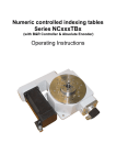
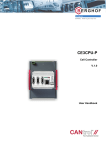
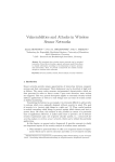
CEDIO-P 24/24/2
Cell Controller
V.1.01
User Handbook
Copyright © Berghof Automationstechnik GmbH
Reproduction and duplication of this document and utilisation and communication of its content is
prohibited, unless with our express permission.
All rights reserved. Damages will be payable in case of infringement.
Disclaimer
The content of this publication was checked for compliance with the hardware and software described.
However, discrepancies may arise, therefore no liability is assumed regarding complete compliance.
The information in this document will be checked regularly and all necessary corrections will be included
in subsequent editions. Suggestions for improvements are always welcome.
Subject to technical changes.
Trademark
CANtrol® // is a registered trademark of Berghof Automationstechnik GmbH
General Information on this Manual
Content:
This manual describes the CANtrol module CEDOP-P 24/24/2 and its modifications. The productrelated information contained herein was up to date at the time of publication of this manual.
Completeness:
This manual is complete only in conjunction with the user manual entitled
„Introduction
to CANtrol Automation System‟
and the product-related hardware or software user manuals required for the particular application.
Standards:
The CANtrol automation system, its components and its use are based on International Standard
IEC 61131 Parts 1 to 4 (EN 61131 Parts 1 to 3 and Supplementary Sheet 1).
Supplementary Sheet 1 of EN 61131 (IEC 61131-4) entitled „User Guidelines‟ is of particular importance
for the user.
Order numbers:
Please see the relevant product overview in the „Introduction to CANtrol Automation System‟ manual for
a list of available products and their order numbers.
Ident. No.:
2813620
You can reach us at:
Berghof Automationstechnik GmbH
Harretstr. 1
72800 Eningen / Germany
Telefon: +49 7121 / 894-0
Telefax: +49 7121 / 894-100
E-Mail: [email protected]
www.berghof.com
Berghof Automationstechnik GmbH works in accordance with DIN EN ISO 9001
Berghof Automationstechnik
CEDIO-P 24/24/2
Update
Version
Date
Subject
1.0
05.07.10
First Version
1.01
22.07.10
Update figure 'Block diagram', 'View of module', Output schematic circuit
diagram, positive-switching' and chapter 'Analog outputs characteristics'.
CEDIO-P-24-24-2_HB_en_2D1362001ZD00.docx
Seite 3
CEDIO-P 24/24/2
Berghof Automation
blank page
Page 4
CEDIO-P-24-24-2_HB_en_2D1362001ZD00.docx
Berghof Automation
CEDIO-P 24/24/2
Contents
1.
GENERAL INFORMATION ........................................................................................ 7
1.1.
About This Manual ................................................................................................................................. 7
1.2.
Hazard Categories and Terminology.................................................................................................... 8
1.3.
Conformity Declaration.......................................................................................................................... 8
1.4.
Qualified Personnel................................................................................................................................ 9
1.5.
Due Diligence .......................................................................................................................................... 9
1.5.1. Working on the controller module .............................................................................................. 9
1.6.
Use as Prescribed ................................................................................................................................ 10
2.
PRODUCT DESCRIPTION ....................................................................................... 11
2.1.
Overview ............................................................................................................................................... 11
2.2.
Technical data ...................................................................................................................................... 13
2.2.1. Technical data of inputs and outputs ....................................................................................... 14
2.3.
Block diagram ....................................................................................................................................... 15
2.4.
View of module and pin assignment .................................................................................................. 16
2.5.
Mounting and connecting ................................................................................................................... 17
2.5.1. Mounting .................................................................................................................................. 17
2.5.2. Connecting up .......................................................................................................................... 17
2.6.
Pin assignment ..................................................................................................................................... 18
2.6.1. 10/100 Base-T network connection (Ethernet) ........................................................................ 18
2.6.2. USB .......................................................................................................................................... 18
2.6.3. CAN bus ................................................................................................................................... 20
2.6.4. Serial Interfaces ....................................................................................................................... 20
2.6.5. E-bus ........................................................................................................................................ 21
3.
CONTROLLER OPERATION ................................................................................... 23
3.1.
Commissioning .................................................................................................................................... 23
3.2.
Function selection, displays, diagnostics ......................................................................................... 23
3.2.1. Status displays ......................................................................................................................... 23
3.3.
Realtime clock with buffer battery ...................................................................................................... 25
4.
DIGITAL I/O: CEDIO-P 24/24/2-0.5-1131 / QDIO 24/24/2-0.5.................................. 27
4.1.
Digital inputs ......................................................................................................................................... 27
4.2.
Inputs with counting function ............................................................................................................. 28
4.3.
Digital outputs, positive-switching..................................................................................................... 29
4.3.1. Output schematic circuit diagram, positive-switching .............................................................. 30
4.3.2. Digital output data .................................................................................................................... 30
CEDIO-P-24-24-2_HB_en_2D1362001ZD00.docx
Page 5
CEDIO-P 24/24/2
Berghof Automation
5.
ANALOG OUTPUTS: CEDIO-P 24/24/2-0.5-1131 AND QDIO 24/24/2-0.5 ............. 31
5.1.
Analog outputs characteristics ...........................................................................................................31
5.1.1. Voltage output (schematic circuit diagram) ..............................................................................31
6.
CODESYS CONTROL SYSTEM CONFIGURATION: CEDIO-P24/24/2 AND
QDIO 24/24/2 ............................................................................................................ 33
6.1.
Structure of the control system configuration ..................................................................................33
6.2.
Digital inputs/outputs ...........................................................................................................................34
6.3.
Diagnostic function ..............................................................................................................................34
6.4.
Encoder function ..................................................................................................................................34
6.5.
Analog outputs .....................................................................................................................................34
7.
ANNEX ...................................................................................................................... 35
7.1.
Environmental Protection ....................................................................................................................35
7.1.1. Emission ...................................................................................................................................35
7.1.2. Disposal....................................................................................................................................35
7.2.
Maintenance/Upkeep ............................................................................................................................35
7.3.
Repairs/Service .....................................................................................................................................35
7.3.1. Warranty ...................................................................................................................................35
7.4.
Nameplate .............................................................................................................................................36
7.5.
Addresses and Bibliography ...............................................................................................................38
7.5.1. Addresses ................................................................................................................................38
7.5.2. Standards/Bibliography ............................................................................................................38
Page 6
CEDIO-P-24-24-2_HB_en_2D1362001ZD00.docx
Berghof Automation
1.
General
General Information
Documentation
This equipment manual is intended for qualified personnel and contains information
regarding mounting, installation, commissioning and maintenance.
The information contained in this manual is subject to change without prior notice.
1.1.
About This Manual
This equipment manual is an integral part of the product. Make sure the equipment
manual is always available near the product‟s point-of-employment. The manual
contains information about the following topics:
Areas of application;
Safety;
Mechanical construction;
Electrical construction;
Connections;
Commissioning;
Care and maintenance;
Decommissioning;
Disposal.
2VF100159FE00.docx
CEDIO-P-24-24-2_HB_en_2D1362001ZD00.docx
Page 7
General
1.2.
Berghof Automation
Hazard Categories and Terminology
Immediate danger
Failure to observe the information indicated by this warning will result in death,
serious injury or extensive property damage.
Potential danger
Failure to observe the information indicated by this warning may result in death,
serious injury or extensive property damage.
Danger
Failure to observe the information indicated by this warning may result in injury or
property damage.
No hazard
Information indicated in this manner provides additional notes concerning the
product.
1.3.
Conformity Declaration
Both the standard version of the controller module and the extension modules
mentioned below comply with and make allowance for the following directives and
standards:
EMP Directive 2004/108/EC
DIN EN 61131-2:2008-4 Programmable controllers
Part 2: Equipment requirements and tests
DIN EN 61000-6-2:2006-3 Electromagnetic compatibility (EMP)
Part 6-2: Generic standard – immunity for industrial environments
DIN EN 61000-6-4:2007-9 Electromagnetic compatibility (EMP)
Part 6-4: Generic standard – electrostatic discharge for industrial environments
Page 8
CEDIO-P-24-24-2_HB_en_2D1362001ZD00.docx
2VF100159FE00.docx
Berghof Automation
1.4.
General
Qualified Personnel
Only qualified personnel may install, operate and maintain the controller module.
Within the context of this documentation and the safety information it contains,
qualified personnel constitutes trained specialists who have the authority to mount,
install, commission, ground and identify equipment, systems and power circuits in
accordance with the standards of safety technology, and who are familiar with the
safety concepts of automation technology.
1.5.
Due Diligence
The operator, or the processor (OEM) must ensure that:
the controller module is only used for the purpose for which it was intended;
the controller module is only operated in impeccable full working order;
the user manual is always available in full and in a legible condition;
only specialists with sufficient qualification and authorisation mount, install,
commission and maintain the controller module;
these specialists are regularly instructed in all relevant questions of occupational health and safety and environmental protection and that they also know
the contents of the user manual and especially of the safety notes therein;
the device markings, identifications, safety and warning notes attached to the
controller module are not removed and are always kept in a legible state;
the national and international regulations for controlling machines and systems
which apply at the relevant usage site are observed;
the relevant information about the controller module and its application and operation is always available to the users
1.5.1.
Working on the controller module
Before carrying out work on the controller module you must always:
first ensure that the controller and the system are in a secure state;
only then switch off the controller and the system and
only now disconnect the controller module from the system.
2VF100159FE00.docx
CEDIO-P-24-24-2_HB_en_2D1362001ZD00.docx
Page 9
General
1.6.
Berghof Automation
Use as Prescribed
This is a modular automation system based on the CANbus, intended for industrial
control applications within the medium to high performance range.
The automation system is designed for use within Overvoltage Category I
(IEC 364-4-443) for the controlling and regulating of machinery and industrial
processes in low-voltage installations in which the rated supply voltage does not
exceed 1,000 VAC (50/60 Hz) or 1,500 VDC.
Qualified project planning and design, proper transport, storage, installation, use
and careful maintenance are essential to the flawless and safe operation of the automation system.
The automation system may only be used within the scope of the data and applications specified in the present documentation and associated user manuals.
The automation system is to be used only as follows:
as prescribed,
in technically flawless condition,
without arbitrary or unauthorized changes and
exclusively by qualified users
The regulations of the German professional and trade associations, the German
technical supervisory board (TÜV), the VDE (Association of German electricians)
or other corresponding national bodies are to be observed.
Safety-oriented (fail-safe) systems
Particular measures are required in connection with the use of SPC in safetyoriented systems. If an SPC is to be used in a safety-oriented system, the user
ought to seek the full advice of the SPC manufacturer in addition to observing any
standards or guidelines on safety installations which may be available.
As with any electronic control system, the failure of particular components may
result in uncontrolled and/or unpredictable operation.
All types of failure and the associated fuse systems are to be taken into account
at system level. The advice of the SPC manufacturer should be sought if necessary.
Page 10
CEDIO-P-24-24-2_HB_en_2D1362001ZD00.docx
2VF100159FE00.docx
Berghof Automation
Product description
2.
Product description
2.1.
Overview
Brief description
The CEDIO-P is a PLC controller with digital and analog I/O and a broad range of
data interfaces. The module can be programmed in conformity with IEC 61131-3
(CoDeSys 2.3).
Mounting
The CEDIO-P is designed for integration into switch cabinets on a DIN rail in a
rough industrial environment. The fanless design and the flash memory make the
cost and effort for maintenance minimal.
Ethernet
An Ethernet interface is available which has 10/100 Mbits. Thanks to the TCP/IP
and UDP/IP protocols it is possible to link it very variably to visualisation software,
to higher order control units or to an IT infrastructure.
USB
The USB host interface provides a widely used peripheral interface. It can be used,
for example to carry out application updates or data migration simply via a USB
stick. Please contact our Technical Support if no driver support is available for a
specific USB device.
CAN interfaces
The CEDIO-P possesses 2 standard CAN interfaces, both of which can be used up
to 1 Mbit/s.
Serial interfaces
The RS232 can also be used as a programming interface.
Realtime clock
A battery-buffered realtime clock can be set at the current time via a software interface.
E-bus extension
The I/O level of the controller can be extended by a maximum of 5 e-bus users via
the E-bus plug-in connector
E-BUS
2VF100154FE01.docx
The e-bus is designed for a maximum of 7 users.
However a single component may contain several users. The CEDIO-P24/24/2
requires 2 of these 7 user slots.
CEDIO-P-24-24-2_HB_en_2D1362001ZD00.docx
Page 11
Product description
Berghof Automation
Features at a glance
400 MHz CPU
User program memory and data memory (RAM):
128 MB onboard 96 MB for application
User program memory (Flash):
32 MB onboard / 24 MB for application
Retention memory, 16 kB
1 Ethernet 10/100 interface
1 USB Host interface V1.1
2 CAN interfaces
1 RS232 serial interface for programming tools and application
I/O level can be extended locally via the internal e-bus for up to 5 users
(digital / analog)
Realtime clock
Scope of supply
The scope of supply of the controller module consists of:
CEDIO-P 24/24/2-0,5-1131; order no.: 201206000
Accessories
Page 12
PLUG-IN CONNECTOR SET FK QDIO24/24/2; order no.: 201604400
containing PHOENIX plug-in connectors 3.81mm.
The same set of plug-in connectors is also used for the QDIO 24/24/2.
CEDIO-P-24-24-2_HB_en_2D1362001ZD00.docx
2VF100154FE01.docx
Berghof Automation
2.2.
Product description
Technical data
CEDIO-P
Module data
Designation
CEDIO-P 24/24/2-0.5-1131
Item no.
201206000
Mounting
Bearing rail NS 35/7.5 EN 50022
Extension
By up to 5 e-bus extension modules, (e.g. QDIO, QAIO)
CPU, user memory
CPU
Freescale PowerPC 400 MHz
Program memory (Flash):
32 MB onboard / 24 MB for application
Program memory and data
memory (RAM)
128 MB onboard / 96 MB for application
Retention memory
16 kB
Development environment
CP1131 (CoDeSys 2.3)
Sizes and weights
Dimensions (WxHxD [mm])
124 x 170 x 85.5 (in-series dimension B = 113/118.5)
Weight
approx. 700 g
Operating conditions
Ambient temperature
0°C to 50°C (if installation instructions are observed)
Relative humidity
Max. 85%, non-condensating
Transportation, storage
Ambient temperature
-20°C to +70°C
Relative humidity
max. 85%, non-condensating
Resistance to vibrations
Vibration
sinus-shaped (EN 60068-2-6) 10 ... 57 Hz
Shock resistance
15 G (approximately 150 m/s²), 10 ms duration, half sine (EN 60068-2-27)
EMC, protection class
Emitted interference
DIN EN 61000-6-4, industrial sector
Immunity to interference
DIN EN 61000-6-2, industrial sector
Protection class
III
Insulation strength
DIN EN 61131-2; DC 500 V test voltage
Protection class
IP20
Energy supply (24 V power pack)
Supply voltage
+24 VDC (-15% / +20%) SELV
max. residual ripple 5%
Power consumption
Max. 0.5 A at +24 VDC (in no-load mode),
max. 10A fuse depending on load on the I/O
Polarity reversal protection
Yes
Potential isolation
Yes, between system electronics (CAN bus) and I/O
2VF100154FE01.docx
CEDIO-P-24-24-2_HB_en_2D1362001ZD00.docx
Page 13
Product description
Berghof Automation
Ethernet interface
Number and type of interfaces
1x 10/100 Base T
Connection technology
RJ45
USB interfaces
Number and type of interfaces
1 x Host USB Rev. 1.1
Mating cycles
Max. 1,000
CAN bus interfaces
Number and type of interfaces
2x standard CAN ISO 11898
Potential isolation
No
Transmission rate
Max. 1 Mbit/s
Terminator resistor
Can be connected
Serial Interfaces
Number and type of interfaces
1x RS232
Potential isolation
No
E-bus interface
Interface types
I/O extension bus for up to 5 e-bus users
Module accommodates 2 e-bus users
Other functions
Realtime clock
2.2.1.
Yes, battery-buffered
Buffer service life typically approx. 10 years / monitoring by means of software
(refer to controller configuration)
Technical data of inputs and outputs
Digital inputs/outputs (DIO)
Number of inputs
24, 4 of which can be used as +24 V encoder inputs;
Counting frequency for 4x evaluation: < 10 kHz
Number of outputs
24 (divided into 2 groups with separate supplies)
Output current
Single output: 0.5 A feasible,
max. 4 A in total per group consisting of 12 outputs
Short circuit protection
Yes
Potential isolation
No
Connection technology
Vertical front wiring for 3.81 plug strips (not included in scope of supply)
Analog outputs
Number
2 analog -/+ 10V outputs
Accuracy at 25°C
+/- 1%
Resolution
12 bits
Connection technology
Vertical front wiring for 3.81 plug strips (not included in scope of supply)
Page 14
CEDIO-P-24-24-2_HB_en_2D1362001ZD00.docx
2VF100154FE01.docx
Berghof Automation
2.3.
Product description
Block diagram
X11
RS232 X3
SIO
Transceiver
CAN0 X1
CAN
Transceiver
CAN1 X2
U QDIO 24/24/2-0,5 I/O
S0 +
Status-LED
E-Bus
E-Bus
Interface
CAN0
CAN1
CPU
RAM
Serial
EEPROM
DC
Serial
EEPROM
X9
+24V;1
X6
12x OUT
1-12
CAN
Transceiver
+5V
GND
+8V
SMPN
DC
CAN1
UCECPU-PDC
SIO
E-Bus
Interface
OUT
D
GND
X8
2x analog
Out
A
+24V;1
24x IN
1-24
X9
GND
X9
+24V;2
X7
12x OUT
13-24
GND
IN
GND
OUT
GND
E-Bus + CAN 1
OUT
U QDIO 24/24/2-0,5 I/O
X9
2VF100413DG01.cdr
2VF100154FE01.docx
CEDIO-P-24-24-2_HB_en_2D1362001ZD00.docx
Page 15
Product description
CAN0
CAN1
X1
RS232
IN4/ENC2B
IN5
IN6
IN7
IN8
IN9
IN10
7
8
9
10 11 12
IN17
IN18
IN19
IN20
IN21
IN22
IN23
IN24
2
IN11
IN12
IN3/ENC2A
6
IN2/ENC1B
5
IN1/ENC1A
4
1
IN14
IN15
3
IN16
View of module and pin assignment
IN13
2.4.
Berghof Automation
13 14 15 16 17 18 19 20 21 22 23 24
X4
X5
X3
X2
S2
S3
1
2
3
4
5
6
7
8
9
10 11 12
X4
IN
24x Digital IN
24x LED IN
13 14 15 16 17 18 19 20 21 22 23 24
X5
IN
IN8
IN9
IN10
IN11
IN12
16
17
18
19
20
21
22
23
24
IN21
IN22
IN23
IN24
12
IN20
11
IN7
10
IN6
9
IN19
8
IN18
X3
RS232
7
IN5
15
6
IN17
14
5
IN4/ENC2B
X5 13
4
IN16
IN2/ENC1B
S3
X2
CAN1
3
IN3/ENC2A
X1
S2
CAN0
2
IN15
OFF
1
IN14
OFF
X4
IN1/ENC1A
ON
IN13
ON
E1
Printable area
for I/O labelling
Batterie
battery
+
E-Bus
OUT
CR2032
CAN1
OUT
OUT7
OUT8
OUT9
OUT10
OUT11
OUT12
X6
OUT6
6
OUT5
5
OUT4
4
OUT3
3
OUT2
A2-
Shield
2
OUT1
A2+
1
A1-
X8
Shield
X10
A1+
Nameplate
1
2
3
4
5
6
7
8
9
10
11
12
OUT18
OUT19
OUT20
OUT21
OUT22
OUT23
OUT24
4
OUT17
3
OUT16
GND
2
OUT15
+24V;2
Run / Stop / Reset
OUT14
GND
X9 1
S1
OUT13
+24V;1
X11
X7 13
14
15
16
17
18
19
20
21
22
23
24
Printable area
for I/O labelling
2x Analog OUT
X10
Analog OUT
55 56
X8
1
2
3
4
5
OUT
6
1
2
3
4
5
6
7
8
9
10 11 12
X6
24x Digital OUT
24x LED OUT
X11
+24V
X9
S1
3
OUT
4
13 14 15 16 17 18 19 20 21 22 23 24
OUT6
OUT7
OUT8
OUT9
OUT10
7
8
10 11 12
2
3
OUT14
OUT15
1
OUT13
X9
GND
5
9
OUT24
OUT5
6
red
OUT11
OUT12
OUT4
5
OUT22
OUT23
OUT3
4
OUT21
OUT2
3
OUT20
OUT1
2
OUT19
A2Schield
1
6
OUT18
A2+
5
OUT17
Shield
4
OUT16
A1-
3
+24;2
Status
2
GND
red
1
+24;1
Status LEDs
3
4
green green
Power
2
X7
Spannungsversorgung
voltage
X8
1
1
A1+
Betriebswahlschalter /
operation mode selector switch
Run / Stop / Reset
4
13 14 15 16 17 18 19 20 21 22 23 24
X6
X7
2VF100414DG01.cdr
Page 16
CEDIO-P-24-24-2_HB_en_2D1362001ZD00.docx
2VF100154FE01.docx
Berghof Automation
Product description
2.5.
Mounting and connecting
2.5.1.
Mounting
Mounting and dismounting and connection of the earth terminal is carried out in
compliance with the description in the CANtrol introductory manual.
2.5.2.
Connecting up
Power supply
The controller is energised from an external 24 VDC external power supply.
Before connecting up, check that the specifications required for the external power
supply are observed.
External power supply (24 VDC)
Output voltage
+24 VDC SELV (-15% / +20%)
Residual ripple
Max. 5%
The DC voltage must not fall below 20.4 V.
The module has two supply connections.
+24V;1 supplies the internal system electronics (inputs), outputs 1-12, and the analog outputs;
+24V;2 supplies outputs 13-24. To disable outputs 13-24 directly the +24V;2 supply can be disconnected on the plus side.
Internal power supply
A power supply for the system electronics is installed to provide a 24-VDC input
voltage (-15% / +20%). The power supply possesses integrated polarity reversal
protection and inrush current limitation.
Both supply lines and the power supplies must be protected by an external short
circuit and overload protection with a maximal tripping current of 5 A in each case
(depending on the number of I/O).
Installation
2VF100154FE01.docx
All connections and lines must be executed so that no faults are caused by inductive and capacitive interference in the controller. The supply lines must be sufficiently resilient to current and voltage.
CEDIO-P-24-24-2_HB_en_2D1362001ZD00.docx
Page 17
Product description
Berghof Automation
2.6.
Pin assignment
2.6.1.
10/100 Base-T network connection (Ethernet)
The 10/100 Base-T onboard Ethernet adapter with RJ-45 connection facilitates
connection to the network. The “LNK” and “RCV” status LED give information
about successful connection to the network.
X11 plug-in connector Assignment:
X11
RJ45
2.6.2.
1
TX+
2
TX-
3
RX+
4
75 Ohm
5
75 Ohm
6
RX-
7
75 Ohm
8
75 Ohm
“LNK” LED
green
ON – ready to operate
“RCV” LED
yellow
FLASHING – receiving data
USB
Devices with USB interfaces can be connected on the USB master port (rev. 1.1).
The only categories of USB devices which can be used by CoDeSys users are
USB sticks. A mouse can only be used at the level of Linux.
The following issues must be taken into account when using USB sticks:
A USB stick may only be unplugged during operation if all file operations
have been completed, otherwise the USB may become unserviceable!
If programs still have files open, the directory cannot be deleted when the USB
stick is unplugged. In this situation file or directory operations cause blockages
because a reading must be taken from a device which is no longer available in
the system. Therefore, when removing the USB stick, always make sure that no
program has any files open on the USB stick.
USB memory sticks can be plugged in and removed during operation. The
plugged-in device is automatically identified and mounted in the /media/usbX
directory. When the USB stick is unplugged the relevant /media/usbX directory
automatically “vanishes” again, if it is no longer being accessed by a program
(see above).
Either the first partition or – if there is no partition – the entire memory is
mounted on the memory stick, i.e. it appears automatically in the appropriate
directory.
Page 18
CEDIO-P-24-24-2_HB_en_2D1362001ZD00.docx
2VF100154FE01.docx
Berghof Automation
Product description
The first stick is mounted under /media/usb0, the second under /media/usb1,
etc. Maximally 8 sticks can be plugged in and used at once (/media/usb [0-7]. If
a new stick is plugged in (or one which has previously been plugged in and
then removed), it will be placed in the directory bearing the lowest free number.
By connecting a USB hub it is possible to operate multiple sticks on one USB
interface. In this case attention must be paid that there are no USB devices still
attached to the hub when it is plugged in and unplugged.
The mechanical structure of the USB port is designed for max. 1,000 mating cycles.
X10 plug-in connector Assignment
X10
USB
B1
VCC
B2
D-
B3
D+
B4
GND
The maximum current available on the USB port is 0.1 A!
Before you use the USB device, check its power consumption.
The controller performs a reset if a USB device requires more than the max. permissible current.
A reset immediately stops the controller and the machine and plant it is controlling. This may cause more extensive damage.
A USB device requiring more current cannot function and may be damaged by
this.
2VF100154FE01.docx
CEDIO-P-24-24-2_HB_en_2D1362001ZD00.docx
Page 19
Product description
2.6.3.
Berghof Automation
CAN bus
The two CAN interfaces (CAN0/CAN1) conform to the ISO 11898 standard and
can be operated up to the maximum Baud rate of 1 MBit/s. The lowest Baud rate
which can be set is 50 kBit/s.
X1/2 plug-in connector Assignment:
X1/2
Sub-D9 M
1
NC (Do not connect)
2
CAN_L
3
CAN_GND
4
NC (Do not connect)
5
NC (Do not connect)
6
NC (Do not connect)
7
CAN_H
8
NC (Do not connect)
9
NC (Do not connect)
A terminating resistor can be connected by means of the S2 (CAN0) and S3
(CAN1) switches.
This is necessary if the appropriate CAN interface is located at the beginning or
end of the relevant CAN-bus topology.
2.6.4.
Serial Interfaces
The RS232 interface X3 has an exceptional position!
Depending on the configuration it can either be used as a Linux console or as a
PPP interface for remote maintenance or as a CoDeSys programming interface.
If the controller is started in the configuration mode, the module can be configured via a serial PPP connection in this mode. Here, too, the connection is made
via X3.
The interfaces in the software are addressed by the following names:
Plug-in connector
X3
Page 20
Software interface
COM1
CEDIO-P-24-24-2_HB_en_2D1362001ZD00.docx
2VF100154FE01.docx
Berghof Automation
X3 plug-in connector
Product description
RS232 assignment:
X3
Sub-D9 F
2.6.5.
1
NC (Do not connect)
2
RXD
3
TXD
4
NC (Do not connect)
5
GND
6
NC (Do not connect)
7
NC (Do not connect)
8
NC (Do not connect)
9
NC (Do not connect)
E-bus
The e-bus enables up to 7 e-bus users to connect up to the controller module.
Please note that some e-bus modules represent 2 e-bus users owing to their
functions, such as for example: CEDIO-P 24/24/2.
2VF100154FE01.docx
CEDIO-P-24-24-2_HB_en_2D1362001ZD00.docx
Page 21
Product description
Berghof Automation
Blank page
Page 22
CEDIO-P-24-24-2_HB_en_2D1362001ZD00.docx
2VF100154FE01.docx
Berghof Automation
3.
Controller operation
Controller operation
When in operation do not plug in, place on, release or touch!
The result can be destruction or malfunction. Before working on the modules
switch off all feeds including those of the connected peripherals, such as externally-supplied sensors, programming devices etc.
MALFUNCTION
3.1.
Commissioning
Before applying the supply voltage check all connections again for correct wiring
and polarity.
Switching on
The module has no mains switch of its own. When switching on the system or
connecting the power supply the PLC is started.
Switching off
When switching off the system or disconnecting it from its own power supply,
the PLC must be switched off.
3.2.
Function selection, displays, diagnostics
3.2.1.
Status displays
The function of the status displays often depends on which software development
environment is used on the PLC.
CP1131-P:
PLC programming with CoDeSys and the Berghof Target Support
Package.
CPC++:
C programming directly on the LINUX operating system.
Ethernet Status LED
S1
Status-LED
2VF100418DG00.cdr
Operating mode
switch (S1)
2VF100155FE00.docx
the purpose of switching from one operating mode to another and for serves
restarting the module.
Position of switch
CP1131-P
CPC++
RUN
CP1131-P program in RUN state. Can
be changed by means of a programming
device.
Freely programmable
STOP
CP1131-P program in STOP state.
Freely programmable
RESET
CP1131-P program restart with deleted
variables (RETAIN variables are not deleted)
Freely programmable
CEDIO-P-24-24-2_HB_en_2D1362001ZD00.docx
Page 23
Controller operation
Status LED
Berghof Automation
4 operating status LED indicate the current status of the voltage supply, module
mode and error messages.
LED
1
Logic status
PWR (green)
ON = correct voltage supply to the module electronics
Status LED for CP1131-P programs
Status 3
(green)
Status 4
(red)
Status 5
(red)
Description
On
Off
User-defined
User program status: RUN
Off
On
User-defined
User program status: STOP
Off
Flashing
User-defined
User program status: FAIL STOP
Flashing
On
User-defined
User program status: Breakpoint STOP
User-defined
User-defined
On
CP1131 mode: FORCE
Basic procedure in case of FAILSTOP:
Establish cause of error (read via web browser)
Eliminate cause of error
Perform reset on controller
Alternatively: Mode selector switch / CoDeSys / web browser
Put controller back into operation
CP1131-P mode FORCE:
FORCE means that the user program is running and a value is compulsorily attributed to at least one variable at the beginning of each cycle via CoDeSys. The
user can therefore see that without this intervention in the sequence of the PLC
program the user program might react differently.
Status LED for CPC++ programs
LED 3 to 5 can be controlled by means of user software.
Ethernet status LED
Page 24
Refer to section: 10/100 Base-T network connection (Ethernet).
CEDIO-P-24-24-2_HB_en_2D1362001ZD00.docx
2VF100155FE00.docx
Berghof Automation
3.3.
Controller operation
Realtime clock with buffer battery
The CEDIO-P is equipped with a realtime clock.
Setting the clock
Either via the web configuration or via the CoDeSys library 'BGHSysLibRtc.lib
Energy supply
A battery is required to supply this clock with energy.
Charge status
The charge status of the buffer battery is monitored by the controller.
The CoDeSys controller configuration for the CEDIO-P shows the charge status of
the battery (refer to section: Controller configuration).
Changing the battery
Batteries are not intended to be changed:
The battery is designed for the entire service life (typ. 10 years) of the controller. Therefore normally the user never needs to change the battery.
If a change of battery is nevertheless necessary, it must be carried out professionally by the manufacturer of the module.
2VF100155FE00.docx
CEDIO-P-24-24-2_HB_en_2D1362001ZD00.docx
Page 25
Controller operation
Berghof Automation
Blank page
Page 26
CEDIO-P-24-24-2_HB_en_2D1362001ZD00.docx
2VF100155FE00.docx
Berghof Automation
4.
4.1.
Digital I/O 24/24/2
Digital I/O: CEDIO-P 24/24/2-0.5-1131 / QDIO 24/24/2-0.5
Type
Number
Digital inputs
24
Of which the number of
counting inputs
4
Digital outputs
24
Digital inputs
Module data
Number
24
Designation
IN1 – IN24
Characteristics
Transition range
5 V to 12 V
Input type according to IEC 61131-2
Type 1, current at 24 V approximately 3.6 mA.
(suitable for electr. outputs)
Type 2, by connecting 2 inputs in
parallel (suitable for contact-based
signals).
Common potential
All inputs are referenced to the same
IO-GND potential
Evaluation
Scan rate by the e-bus 250 µs
Scan rate by CoDeSys at least 1 ms
Status display
via orange LED
Current-voltage curve
VIN (V)
Type 1
30
25
ON
20
15
10
5
OFF
0
-3
0
5
10
IIN (mA)
15
2VF100415DG00.cdr
2VF100156FE01.docx
CEDIO-P-24-24-2_HB_en_2D1362001ZD00.docx
Page 27
Digital I/O 24/24/2
4.2.
Berghof Automation
Inputs with counting function
Counting units
Number
2 counting units
Connection
ENC1A = IN1
ENC1B = IN2
ENC2A = IN3
ENC2B = IN4
Each counting unit is connected by means of
two 24-V inputs. The status of the inputs used
as counters can also be read-in.
Counting modes
Quadrature decoders
Maximum counting frequency
10 kHz
Minimum pulse width
200 µs
Counter width
32 bits in the CodeSys system
Current-voltage curve
400 µs
min. 200 µs min. 200 µs
signal A
signal B
counted
measurand
1
2
3
4
5
6
7
8
9
10
2VF100416DG00.cdr
Page 28
CEDIO-P-24-24-2_HB_en_2D1362001ZD00.docx
2VF100156FE01.docx
Berghof Automation
4.3.
Digital I/O 24/24/2
Digital outputs, positive-switching
Number
24
Group 1
OUT1-OUT12
Group 2
(can be switched off separately)
OUT13-OUT24
In the case of overvoltage >32 V and / or energetic recovery the module
may be destroyed. This is a fire hazard!
If you adjust outputs to 24 V from the outside for test purposes, the relevant
module must be supplied with the same voltage, otherwise energetic recovery
may occur, which is not permitted.
OVERVOLTAGE
Outputs
The outputs are positive-switching, 24-V outputs. Output current max.
500 mA per output. The outputs have a common reference potential (IO_GND).
If there is no data connection to the CPU or if the internal supply of the module is
not sufficient, the outputs automatically switch to „0‟ (LOW).
Protected output
In case of overload the current
is limited (typically 3A). After
the overload has been eliminated, the output is again available. Fast de-excitation by
means of a 41 V terminal voltage in relation to L+ protects all
outputs against induced peak
voltages with inductive loads.
If thermal loads occur owing to
energetic recovery or fast deexcitation, the overload protection may react prematurely also
in the case of outputs which are
not involved.
IN
Einschalten auf Kurzschluss
turn on into short circuit
t
IL
3-6 A
IL(SCp)
6A
IL(SCr)
3A
toff(SC)
t
2VF100392DG00.cdr
Der max.The max. output current is 0.5 A
The output stage is protected against overload, which must be taken into account
for high inrush currents from lamps, for example.
2VF100156FE01.docx
CEDIO-P-24-24-2_HB_en_2D1362001ZD00.docx
Page 29
Digital I/O 24/24/2
4.3.1.
Berghof Automation
Output schematic circuit diagram, positive-switching
L+
+ 24 V
L+
OUT
< V.0002
QDIO
CEDIO-P < V.0004
DGND
+ 24 V
OUT
QDIO
> V.0002
CEDIO-P > V.0004
GND
GND
2VF100420DG01.cdr
4.3.2.
Digital output data
Module data
Type of outputs
Protection circuit for inductive loads
Power loss due to de-excitation
Status display
Semiconductor, non-storing
Fast de-excitation 41 V terminal
voltage (typ.) approx. +24 V
max. 0.5 W / output
max. 4 W / module
Orange LED per output
Overload protection
Short circuit protection
Response threshold
In case of thermal overload
1) 2) 3)
Electronic current limitation typically 3 A. Avoid tripping under
normal service conditions.
1) Current is limited electronically. Triggering the short circuit protection causes thermal overload and
tripping of the thermal overload protection
2) Starting from cold, maximally 10,000 permissible short circuits.
3) Duration of a short circuit, maximally 500 hours.
Exit delay
Page 30
if „0‟ is after „1‟
if „1‟ is after „0‟
typically 1ms
typically 1ms
Output capacity
< 100 nF
Rated voltage
Voltage drop (in the case of rated current)
DC +24 V
< 0.1 V
Rated current with „1‟ signal
0.5 A
Total current of all outputs per group
max. 4 A
Two outputs switched in parallel
for logic link
for increased output
permissible
permissible up to 1 A
CEDIO-P-24-24-2_HB_en_2D1362001ZD00.docx
2VF100156FE01.docx
Berghof Automation
Analog outputs 24/24/2-0.5
5.
Analog outputs:
CEDIO-P 24/24/2-0.5-1131 and QDIO 24/24/2-0.5
5.1.
Analog outputs characteristics
Module data
Number
2
Designation
AO1-AO2
Connections per output
PE for shield, GND, AO
Voltage output
Signal range
-10..+10V
Load impedance range
>= 1000 Ohm, <10 nF
Overload
Short-circuit proof
Reference potential
IO-GND
Digital resolution
12 bits
Accuracy at 25°C
+/- 1%
Dynamic characteristics
5.1.1.
Maximum setting time if there is a reversal covering the full range (99.5%)
10 ms
Greatest temporary deviation during
electrical interference test
+/-10 %
Voltage output (schematic circuit diagram)
D
A
+
-
OUT
RL
AGND
Shield
2VF100417DG00.cdr
2VF100157FE01.docx
CEDIO-P-24-24-2_HB_en_2D1362001ZD00.docx
Page 31
Analog outputs 24/24/2-0.5
Berghof Automation
Blank page
Page 32
CEDIO-P-24-24-2_HB_en_2D1362001ZD00.docx
2VF100157FE01.docx
Berghof Automation
6.
CoDeSys control system configuration
CoDeSys control system configuration:
CEDIO-P24/24/2 and QDIO 24/24/2
Prerequisites:
Berghof Target V204 and Firmware V2.12.0
6.1.
Structure of the control system configuration
The CANtrol controllers are modular in design. From the point of view of the control
system configuration they consist of a CPU module and an I/O module which is
connected to the CPU module via the e-bus.
This means that for the CEDIO 24/24/2 the control system is configured as follows:
PowerPC-CPU module
E-bus Master
QDIO_24_24_2
If a QDIO24/24/2 is used additionally, a further QDIO_24_24_2 element is
added.
QDIO_24_24_2 is used by CEDIO24/24/2 and QDIO24/24/2.
2VF100158FE00.docx
CEDIO-P-24-24-2_HB_en_2D1362001ZD00.docx
Page 33
CoDeSys control system configuration
6.2.
Berghof Automation
Digital inputs/outputs
The QDIO24/24/2 and the CEDIO 24/24/2 possess 24 digital inputs and 24 digital
outputs. These are supplied by 2 separate voltages. On the CEDIO24/24/2 the
module electronics are also supplied with supply voltage 1.
The control system configuration encompasses a total of 32 inputs and 32 outputs.
Some of these inputs are used for diagnosing the module. The other I/O, which are
not being used, remain reserved and may not be used.
6.3.
6.4.
Input bit
Function
0 to 23
24 V input
24 to 26
Diagnosis
27 to 31
Reserved
Output bit
Function I
0 to 23
24 V output
24 to 31
Reserved
Diagnostic function
Input bit
Bit = TRUE
24
Supply voltage 1 OK (X9; 24V;1)
25
Supply voltage 2 OK (X9; 24V;2)
26
Battery voltage OK (CEDIO-P24/24/2 only)
Encoder function
Up to two 24-volt encoders can be connected on the inputs. Maximum counting
frequency: 10 KHz.
6.5.
Input bit
Function
0 and 1
Encoder 1 (X4; IN1 and IN2)
2 and 3
Encoder 2 (X4; IN3 and IN4)
Analog outputs
Values range from –10000 to +10000 mV
If higher or lower values are configured the controller reports a failure, goes into
the Fail Stop state and a diagnostic entry bearing the value:
xxxxxxxx:ffffffd3:67020088: CP1131 : eBERR:eIO_FAIL is written.
Page 34
CEDIO-P-24-24-2_HB_en_2D1362001ZD00.docx
2VF100158FE00.docx
Berghof Automation
Annex
7.
Annex
7.1.
Environmental Protection
7.1.1.
Emission
When used correctly, our modules do not produce any harmful emissions.
7.1.2.
Disposal
At the end of their service life, modules may be returned to the manufacturer
against payment of an all-inclusive charge to cover costs. The manufacturer
will then arrange for the modules to be recycled.
7.2.
Maintenance/Upkeep
Do not insert, apply, detach or touch connections while in operation – risk
of destruction or malfunction.
Disconnect all incoming power supplies before working on our modules; this also
applies to connected peripheral equipment such as externally powered sensors,
programming devices, etc. All ventilation openings must always be kept free of
any obstruction.
The modules are maintenance-free when used correctly.
Clean only with a dry, non-fluffing cloth.
Do not use detergents.
7.3.
Repairs/Service
Repair work may only be carried out by the manufacturer or its authorised service
engineers.
7.3.1.
Warranty
Sold under statutory warranty conditions. Warranty lapses in the event of unauthorised attempts to repair the equipment and/or product, or in the event of any other
form of intervention.
2VF100055FE02.docx
CEDIO-P-24-24-2_HB_en_2D1362001ZD00.docx
Page 35
Annex
7.4.
Berghof Automation
Nameplate
2VF100080DG01.cdr
Page 36
CEDIO-P-24-24-2_HB_en_2D1362001ZD00.docx
2VF100055FE02.docx
Berghof Automation
Annex
1
Barcode
same as identification number.
2
Module type
plain-text name of module.
3
Identification no.
module's identification number.
4
5
6
7
8
Model/order no.
You only need to give this number when ordering a module. The module will be
supplied in its current hardware and software version.
Version
defines the design-level of the module as supplied ex-works.
Supply voltage
Date
internal code.
CE mark
The ‘Version’ (supply version) panel specifies the design-level of the module as supplied ex-works.
When replacing a module, users, with the CNW (CANtrol Node Wizard) tool, can
read off the current software version of the newly supplied module, and then reload their 'own' software version for a particular project if necessary.
With the latter in mind, before the download you should always keep a record of
the existing software levels in your project documentation (software version, node
IDs, baud rate, etc.).
2VF100055FE02.docx
CEDIO-P-24-24-2_HB_en_2D1362001ZD00.docx
Page 37
Annex
Berghof Automation
7.5.
Addresses and Bibliography
7.5.1.
Addresses
CiA
'CAN in Automation', international manufacturers and users organisation
for CAN users in the field of automation:
CiA - CAN in Automation e.V.
Am Weichselgarten 26
D-91058 Erlangen /Germany
e-mail: [email protected]
http://www.can-cia.de
DIN-EN Standards
Beuth Verlag GmbH or
10772 Berlin
VDE-Verlag GmbH
10625 Berlin
IEC Standards
VDE Verlag GmbH
10625 Berlin
Internet search
http://www.iec.ch/
7.5.2.
or
Standards/Bibliography
IEC61131-1/EN61131-1
Programmable controllers Part 1: General information
IEC61131-2/EN61131-2
Programmable controllers Part 2: Equipment requirements and tests
IEC61131-3/EN61131-3
Programmable controllers Part 3: Programming languages
IEC61131-4/EN61131Bl1
Programmable logic controllers
Supplementary Sheet 1: User guidelines
IEC61000-6-4 /
EN61000-6-4
German EMC Act: Emitted interference
IEC61000-6-2 /
EN61000-6-2
German EMC Act: Noise immunity
ISO/DIS 11898
Draft International Standard: Road vehicles - Interchange of digital information Controller Area Network (CAN) for high-speed communication
EN 954-1
Safety of machinery: Safety-related parts of control systems (Part 1)
Bibliography
A variety of specialist publications on the CANbus is available from specialist
bookshops, or can be obtained through the CiA users' organisation.
Our Technical Support team will be glad to provide other literature references on
request.
Page 38
CEDIO-P-24-24-2_HB_en_2D1362001ZD00.docx
2VF100055FE02.docx