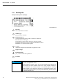
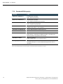
1
USER MANUAL 1.2 DC1100 Dialog-Controller Basic Plus Copyright © Berghof Automationstechnik GmbH Reproduction and duplication of this document and utilisation and communication of its content is prohibited, unless with our express permission. All rights reserved. Damages will be payable in case of infringement. Disclaimer The content of this publication was checked for compliance with the hardware and software described. However, discrepancies may arise, therefore no liability is assumed regarding complete compliance. The information in this document will be checked regularly and all necessary corrections will be included in subsequent editions. Suggestions for improvements are always welcome. Subject to technical changes. Trademarks CANtrol® and CANtrol®- dialog are registered trademarks of Berghof Automationstechnik GmbH Microsoft®, Windows® and the Windows® Logo are registered trademarks of Microsoft Corporation in the USA and other countries. EtherCAT® is a registered trademark and patented technology, licensed from Beckhoff Automation GmbH, Germany. CiA® and CANopen® are registered community trademarks of CAN in Automation e.V. All rights reserved by the individual copyright holders. Content Completeness General Information on this Manual This equipment manual contains product-specific information valid at the time of publication. This equipment manual is only complete in conjunction with the product-related hardware and software user manuals required for the individual application. You can reach us at: Berghof Automationstechnik GmbH Harretstr. 1 72800 Eningen Germany T +49.7121.894-0 F +49.7121.894-100 e-mail: [email protected] www.berghof.com Berghof Automationstechnik GmbH works in accordance with DIN EN ISO 9001:2000. USER MANUAL 1.2 | DC1100 Update Version Date Subject 1.01 12.09.2012 First Version 1.1 23.11.2012 Update of the title page Update of the trademarks Update in the 'Conformity Declaration' section Integration of DC1107 WT in chapter 'Product description', sections 'Technical data', 'Front view', 'Dimensions', 'Panel cut-out' and 'Screw-on mounting' 1.2 19.07.2013 Transition into new CD Berghof Automationstechnik GmbH | Harretstrasse 1 | 72800 Eningen | www.berghof.com DC1103_HB_en_2D1672003ZD00.docx 3 USER MANUAL 1.2 | DC1100 Blank page 4 Berghof Automationstechnik GmbH | Harretstrasse 1 | 72800 Eningen | www.berghof.com DC1103_HB_en_2D1672003ZD00.docx USER MANUAL 1.2 | DC1100 Contents 1. GENERAL ..................................................................................................................................... 7 1.1. About this manual ........................................................................................................................ 7 1.2. Hazard categories and terminology ............................................................................................. 8 1.3. Qualified personnel ...................................................................................................................... 9 1.4. Due diligence ............................................................................................................................... 9 1.5. Basic safety measures ............................................................................................................... 10 1.6. Intended use............................................................................................................................... 11 1.7. Declaration of conformity .......................................................................................................... 12 1.8. Transport and setup ................................................................................................................... 13 2. PRODUCT DESCRIPTION .......................................................................................................... 15 2.1. Identification .............................................................................................................................. 16 2.2. 2.2.1. 2.2.2. 2.2.3. 2.2.4. 2.2.5. 2.2.6. 2.2.7. 2.2.8. Layout of the DC1100 Dialog-Controller .................................................................................... 17 Block diagram .............................................................................................................................. 17 Technical data DC1100................................................................................................................. 18 Front view of the DC1103 QK ....................................................................................................... 20 Dimensions of the DC1103 QK ..................................................................................................... 20 Panel cut-out for the DC1103 QK .................................................................................................. 21 Front view of the DC1107 WT ....................................................................................................... 22 Dimensions of the DC1107 WT ..................................................................................................... 22 Panel cut-out for the DC1107 WT ................................................................................................. 23 2.3. 2.3.1. 2.3.2. 2.3.3. 2.3.4. Mounting and connecting .......................................................................................................... 24 Mounting and installing................................................................................................................. 24 Snap In mounting for 3.5“ devices................................................................................................. 24 Screw-on mounting for 7“ devices ................................................................................................. 25 Connecting .................................................................................................................................. 25 2.4. 2.4.1. 2.4.2. 2.4.3. 2.4.4. 2.4.5. 2.4.6. 2.4.7. Pin assignment .......................................................................................................................... 26 Plug-in connector overview........................................................................................................... 26 Power supply ............................................................................................................................... 26 10/100 Base-T network connection (Ethernet) ............................................................................... 26 USB............................................................................................................................................. 27 CAN bus ...................................................................................................................................... 28 Serial interfaces ........................................................................................................................... 29 E-bus........................................................................................................................................... 31 2.5. SD Card ...................................................................................................................................... 32 3. DIALOG-CONTROLLER OPERATION ........................................................................................ 33 3.1. Commissioning .......................................................................................................................... 33 3.2. Function selection, indicators, diagnostics .............................................................................. 33 3.2.1. Status indicators .......................................................................................................................... 33 3.3. Service menu ............................................................................................................................. 35 3.3.1. Using the service menu ................................................................................................................ 36 3.3.2. Parameter window ....................................................................................................................... 36 Berghof Automationstechnik GmbH | Harretstrasse 1 | 72800 Eningen | www.berghof.com DC1103_HB_en_2D1672003ZD00.docx 5 USER MANUAL 1.2 | DC1100 “Config” service menu .................................................................................................................. 37 “PLC” service menu...................................................................................................................... 40 “INFO” service menu .................................................................................................................... 41 “Display” service menu ................................................................................................................. 42 3.3.3. PLC window ................................................................................................................................. 43 3.4. Decommissioning ...................................................................................................................... 46 3.4.1. Disposal ....................................................................................................................................... 46 3.5. Maintenance ............................................................................................................................... 47 3.6. Help in case of problems ........................................................................................................... 47 4. MAINTENANCE........................................................................................................................... 49 4.1. Real-time clock with backup battery .......................................................................................... 50 5. CHEMICAL RESISTANCE ........................................................................................................... 51 5.1. Resistance of the touch screen ................................................................................................. 51 5.2. Resistance of the front REFLEX foil towards chemicals ........................................................... 52 5.2.1. General resistance of the foil ........................................................................................................ 52 5.2.2. Environmental values ................................................................................................................... 52 6. COPYRIGHT AND SOFTWARE LICENSES ................................................................................. 53 7. ANNEX ........................................................................................................................................ 55 7.1. Environmental Protection .......................................................................................................... 55 7.1.1. Emission ...................................................................................................................................... 55 7.1.2. Disposal ....................................................................................................................................... 55 7.2. Maintenance/Upkeep .................................................................................................................. 55 7.3. Repairs/Service .......................................................................................................................... 55 7.3.1. Warranty ...................................................................................................................................... 55 7.4. Nameplate................................................................................................................................... 56 Nameplate descriptions (example) ................................................................................................ 56 7.5. Addresses and Bibliography...................................................................................................... 57 7.5.1. Addresses .................................................................................................................................... 57 7.5.2. Standards/Bibliography................................................................................................................. 58 6 Berghof Automationstechnik GmbH | Harretstrasse 1 | 72800 Eningen | www.berghof.com DC1103_HB_en_2D1672003ZD00.docx USER MANUAL 1.2 | DC1100 1. General Documentation This equipment manual is intended for qualified personnel and contains information regarding the mounting, installation, commissioning and maintenance of the Dialog-Controller. The information contained in this manual is subject to change without prior notice. 1.1. About this manual This equipment manual is an integral part of the product. Make sure the equipment manual is always available near the product’s point-of-employment. The manual contains information about the following topics: Areas of application Safety Mechanical construction Electrical construction Connections Commissioning Care and maintenance Decommissioning Disposal Berghof Automationstechnik GmbH | Harretstrasse 1 | 72800 Eningen | www.berghof.com 2VF100196FE02.docx | DC1103_HB_en_2D1672003ZD00.docx 7 USER MANUAL 1.2 | DC1100 1.2. Hazard categories and terminology DANGER Immediate danger Failure to observe the information indicated by this warning will result in death, serious injury or extensive property damage. WARNING Potential danger Failure to observe the information indicated by this warning may result in death, serious injury or extensive property damage. CAUTION Danger Failure to observe the information indicated by this warning may result in injury or property damage. NOTICE No hazard Information indicated in this manner provides additional notes concerning the product. 8 Berghof Automationstechnik GmbH | Harretstrasse 1 | 72800 Eningen | www.berghof.com DC1103_HB_en_2D1672003ZD00.docx | 2VF100196FE02.docx USER MANUAL 1.2 | DC1100 1.3. Qualified personnel Only qualified personnel may install, operate and maintain the Dialog-Controller. Within the context of this documentation and the safety information it contains, qualified personnel constitutes trained specialists who have the authority to mount, install, commission, ground and identify equipment, systems and power circuits in accordance with the standards of safety technology, and who are familiar with the safety concepts of automation technology. 1.4. Due diligence The operator or original equipment manufacturer (OEM) must ensure … that the Dialog-Controller is only employed for its intended use. that the Dialog-Controller is only employed in a fault-free, operational state. that the equipment manual is always maintained in a complete and legible condition and is available at the point-of-employment of the Dialog-Controller. that only properly qualified and authorized personnel mount, install, commission and maintain the Dialog-Controller. that these specialists receive regular and ongoing instruction in all pertinent questions related to work safety and environmental protection and that they are familiar with the contents of the equipment manual, in particular, with the safety information it contains. that the equipment identifiers as well as safety and warning information applied to the Dialog-Controller are not removed and that they are maintained in a legible condition. that all international, federal, state and local ordinances governing the control of machinery and equipment applicable at the location at which the Dialog-Controller is employed are complied with. that the users always have available all relevant information they require with regard to the DialogController and its employment. Berghof Automationstechnik GmbH | Harretstrasse 1 | 72800 Eningen | www.berghof.com 2VF100196FE02.docx | DC1103_HB_en_2D1672003ZD00.docx 9 USER MANUAL 1.2 | DC1100 1.5. Basic safety measures WARNING HAZARDOUS VOLTAGE If damage can be seen on the faceplate of the Dialog-Controller, the device must not be operated any more! It must be disconnected from the supply voltage immediately! Besides the danger of injury owing to the visibly sharp edges, there is also the risk of touching parts under high voltage. Contact with high voltage can still occur even some time after the supply voltage has been shut off. Working on the Dialog-Controller Before beginning work on the Dialog-Controller you must always first ensure that the equipment is in a safe state, then first switch the Dialog-Controller off, followed by the equipment, and only then disconnect the Dialog-Controller from the equipment. WARNING Hazards due to unforeseeable functional and processing movements when the Dialog-Controller is disconnected. These can result in death, serious injury or extensive property damage. HAZARDOUS PROCESSES All equipment components must be disconnected from the Dialog-Controller whenever the Dialog-Controller is not being used for operational or control purposes, e.g., during maintenance or during functional checks after repairs. Lock out and tag out all equipment components after they have been switched off! Opening the Dialog-Controller First, please note all the tasks steps outlined in the above section “Working on the Dialog-Controller”. The supply voltage must be switched off before opening the housing or when components are being installed or removed. To do this, switch the power supply to the Dialog-Controller off. Then remove the plug from the power supply socket on the Dialog-Controller. WARNING Do not open the housing cover with the power switched on! Hazard due to contact with live components. This can result in death, serious injury or extensive property damage. HAZARDOUS VOLTAGE 10 Only open the housing cover once the Dialog-Controller has been safely disconnected from the power supply. Berghof Automationstechnik GmbH | Harretstrasse 1 | 72800 Eningen | www.berghof.com DC1103_HB_en_2D1672003ZD00.docx | 2VF100196FE02.docx USER MANUAL 1.2 | DC1100 1.6. Intended use This is a modular automation system based on the CANbus, intended for industrial control applications within the medium to high performance range. The automation system is designed for use within Overvoltage Category I (IEC 364-4-443) for the controlling and regulating of machinery and industrial processes in low-voltage installations in which the rated supply voltage does not exceed 1,000 VAC (50/60 Hz) or 1,500 VDC. Qualified project planning and design, proper transport, storage, installation, use and careful maintenance are essential to the flawless and safe operation of the automation system. The automation system may only be used within the scope of the data and applications specified in the present documentation and associated user manuals. The automation system is to be used only as follows: as prescribed, in technically flawless condition, without arbitrary or unauthorized changes and exclusively by qualified users The regulations of the German professional and trade associations, the German technical supervisory board (TÜV), the VDE (Association of German electricians) or other corresponding national bodies are to be observed. Safety-oriented (fail-safe) systems Particular measures are required in connection with the use of SPC in safety-oriented systems. If an SPC is to be used in a safety-oriented system, the user ought to seek the full advice of the SPC manufacturer in addition to observing any standards or guidelines on safety installations which may be available. WARNING As with any electronic control system, the failure of particular components may result in uncontrolled and/or unpredictable operation. All types of failure and the associated fuse systems are to be taken into account at system level. The advice of the SPC manufacturer should be sought if necessary. Berghof Automationstechnik GmbH | Harretstrasse 1 | 72800 Eningen | www.berghof.com 2VF100196FE02.docx | DC1103_HB_en_2D1672003ZD00.docx 11 USER MANUAL 1.2 | DC1100 1.7. Declaration of conformity Both the standard version of the Dialog-Controller and with the extension modules mentioned below comply with and make allowance for the following directives and standards: EMP Directive 2004/108/EC EN 61131-2:2009-1 Programmable logic controllers Part 2: Equipment requirements and tests Class B, connector cable of the I/O, max. 30 m EN 61000-6-2:2011-6 Electromagnetic compatibility (EMP) Part 6-2: Generic standard – immunity for industrial environments EN 61000-6-3:2011-9 Electromagnetic compatibility (EMP) Part 6-4: Generic standard – electrostatic discharge for industrial environments 12 Berghof Automationstechnik GmbH | Harretstrasse 1 | 72800 Eningen | www.berghof.com DC1103_HB_en_2D1672003ZD00.docx | 2VF100196FE02.docx USER MANUAL 1.2 | DC1100 1.8. Transport and setup NOTICE Please note the specified storage conditions in the section ‘Technical specifications’. Transport Protect the Dialog-Controller against extreme mechanical stress during transport. Always transport the Dialog-Controller in its original packaging. The built-in components are extremely sensitive to jarring and strong vibrations. CAUTION Condensation hazard resulting from climatic fluctuations. Risk of damage as a result of moisture forming on or in the Dialog-Controller (condensation). This can result in destruction of the device or consequential damages. CONDENSATION After storage or transport in cold weather or under conditions of strongly fluctuating temperatures, the Dialog-Controller must be allowed to slowly adjust to the ambient temperature at its point of use before it can be taken into service. In case of condensation, the unit may not be taken into service for at least 12 hours (temperature compensation). Unpacking Proceed as follows: Inspect the packaging for any external damage. If the packaging is severely damaged or if damage to the contents can be detected, do not open the packaging any further. Immediately contact your shipper and your supplier. Remove the packaging. Do not discard the original packaging! The packaging can be used for subsequent transport. Inspect the contents for visible shipping damage. Check the contents against the order for completeness. Save all included documentation. This documentation contains important information concerning the Dialog-Controller and is an integral part of the product. If shipping damage is detected or if the received contents do not agree with the order, please contact your supplier immediately. Setup This Dialog-Controller is designed for installation in fully enclosed circuit cabinets of industrial machinery and equipment. When installing the Dialog-Controller, take particular care to ensure that the included seal profiles are not damaged. Also ensure compliance with the ambient conditions specified under ‘Technical specifications’. Berghof Automationstechnik GmbH | Harretstrasse 1 | 72800 Eningen | www.berghof.com 2VF100196FE02.docx | DC1103_HB_en_2D1672003ZD00.docx 13 USER MANUAL 1.2 | DC1100 Blank page 14 Berghof Automationstechnik GmbH | Harretstrasse 1 | 72800 Eningen | www.berghof.com DC1103_HB_en_2D1672003ZD00.docx | 2VF100196FE02.docx USER MANUAL 1.2 | DC1100 2. Product description The Dialog-Controller is a realtime-capable control module with a display and a broad range of data interfaces. The module can be programmed in conformity with IEC 61131-3 (CODESYS 2.3). Brief description Mounting Dialog-Controllers are designed for installation on the front panel or for building into a switching cabinet in a rough, industrial environment. The fanless design and the flash memory make the cost and effort for maintenance minimal. Processors The Dialog-Controller is equipped with either a 266-MHz or a 400-MHz clocked POWERPCTM processor from Freescale. Display There are 3.5" and 7" TFT displays to choose from. Ethernet Up to two 10/100 Mbit/s Ethernet interfaces are available. Thanks to the TCP/IP and UDP/IP protocols it is possible to link it very variably to visualisation software, to higher order control units or an IT infrastructure. The second Ethernet interface is implemented as an EtherCAT interface. USB The USB host interface provides a widely-used peripheral interface. For example it can be used to carry out application updates or data migration simply via a USB stick. Please contact our Technical Support if no driver support is available for a specific USB device. CAN interfaces The Dialog-Controller possesses 1 standard CAN interface which can be used up to 1 Mbit/s. Serial interfaces In all, 2 serial interfaces can be deployed on the Dialog-Controller. The RS232 is supplemented by an RS485 interface. E-bus extension The I/O level of the Dialog-Controller can be extended by a maximum of 7 E-bus users via the E-bus plug-in connector. The E-bus interface is not available in the “EtherCAT” device option. Realtime clock A battery-buffered realtime clock can be set at the current time via a software interface. SD card reader With the off-the-shelf MMC/SD card interface data can be written onto or read off memory cards. Berghof Automationstechnik GmbH | Harretstrasse 1 | 72800 Eningen | www.berghof.com 2VF100182FE03.docx | DC1103_HB_en_2D1672003ZD00.docx 15 USER MANUAL 1.2 | DC1100 Performance features – an overview Freescale POWERPCTM CPU 266 (400) MHz User program and data memory (RAM): 64 (128) MB on board / 32 (96) MB for application User program memory (Flash): 16 (32) MB on board / 8 (24) MB for application RetainMemory, 16 kB 1 Ethernet 10/100 interface; optional second Ethernet interface for EtherCAT 1 USB Host interface 1 CAN interface 1 RS232 serial interface for programming tools and application 1 RS485 serial interface I/O level can be extended locally via the internal E-bus for up to 7 users (digital / analog); optional Realtime clock MMC/SD card slot Scope of supply The scope of supply of the controller module consists of: Dialog-Controller DC11xx incl. 2-pin plug-in connector for power supply 2.1. Identification Product: Dialog-Controller, Type DC11xx Identification code The features of the Dialog-Controller (see “Annex, Nameplate”) can be itemised according to the identification code. 1 2 3 4 5 6 7 D C 1 1 0 3 Q 8 9 10 K 11 12 13 14 15 M P ... 6 6 Screen size (diagonal) Model BASIC+ = extended basic equipment TL = Twin LAN 03 = 3,5” 07 = 7,0” Resolution Q = QVGA 320 x 240 W = WVGA 800 x 480 B A S I C + Processor type MP266 = Power PC 266 MHz MP400 = Power PC 400 MHz Activation method T = Touchpanel K = Keyboard A = Touch + Keyboard 2VF100519DG01.cdr 16 Berghof Automationstechnik GmbH | Harretstrasse 1 | 72800 Eningen | www.berghof.com DC1103_HB_en_2D1672003ZD00.docx | 2VF100182FE03.docx USER MANUAL 1.2 | DC1100 2.2. Layout of the DC1100 Dialog-Controller 2.2.1. Block diagram Display Touch / Keyboard Display FRONT Controller X7 USB Transceiver X6 EthernetTransceiver X5 EthernetTransceiver alternativ / alternatively X2 TouchController DisplayController E-Bus SD MMC RS232 Graphic CAN USB SIO Flash CPU RAM X3 RS485 X1 +24 V L1+ M X4 CANTransceiver BASIS 2VF100521DG02.VSD Berghof Automationstechnik GmbH | Harretstrasse 1 | 72800 Eningen | www.berghof.com 2VF100182FE03.docx | DC1103_HB_en_2D1672003ZD00.docx 17 USER MANUAL 1.2 | DC1100 2.2.2. Technical data DC1100 Module data DC1103 DC1105 Display QVGA VGA Diagonal 3.5“ 7“ Wide Art. no. 270005300 - Resolution 320 x 240 pixels 800 x 480 pixels Colours TFT: 256 (8 bits / pixels) TFT: 65536 (16 bits / pixels) CPU 266 MHz CPU 400 MHz CPU Program memory (Flash) 16 MB / 8 MB for application 32 MB Onboard / 24 MB for application Program / data memory (RAM) 64 MB, 32 MB for application 128 MB Onboard / 96 MB for application Retain memory 16 kB Development environment CODESYS PLC programming tool Input Touch operation and / or membrane keyboard CPU, user memory Sizes and weights Dimensions (WxHxD [mm]) 232x105x40 Weight 700 g 215x156x45 Operating conditions Ambient temperature 0 °C to 55 °C (if installation instructions are observed) Relative air humidity Max. 85 %, non-condensating Transportation, storage Ambient temperature -20 °C to +70 °C Relative air humidity Max. 85 %, non-condensating EMC, protection class Emitted interference EN 61000-6-3, residential area Immunity to interference EN 61000-6-2, industrial sector Protection type IP20 (front IP54) Energy supply (24 V power supply unit) 18 Supply voltage +24 VDC (-15 % / +20 %) SELV, max. proportion of a.c. voltage 5 % Power consumption typ. 1.0 A, max. 2.0 A at +24 VDC Reverse voltage protection Yes Bridging in case of power failure 10 ms at < 20.4 VDC; Power Fail < 19.2 VDC Berghof Automationstechnik GmbH | Harretstrasse 1 | 72800 Eningen | www.berghof.com DC1103_HB_en_2D1672003ZD00.docx | 2VF100182FE03.docx USER MANUAL 1.2 | DC1100 Module data Ethernet interfaces Number / type of interfaces 1 x 10/100 Base-T on RJ45 plug-in connector / nd Optional: 2 Ethernet interface as the EtherCAT Master USB interface Number / type of interface 1 x Host USB Rev. 1.1 (rear side) CAN bus interface Number / type of interface 1 x Standard CAN ISO 11898 isolated Serial interfaces Number / type of interfaces 1 x RS232, 1x RS485 E-bus interface Type of interfaces I/O extension bus, max. 7 users (alternative to 2 nd Ethernet interface) Other functions Realtime clock Yes, battery-buffered SD card Optional Berghof Automationstechnik GmbH | Harretstrasse 1 | 72800 Eningen | www.berghof.com 2VF100182FE03.docx | DC1103_HB_en_2D1672003ZD00.docx 19 USER MANUAL 1.2 | DC1100 2.2.3. Front view of the DC1103 QK 2VF100517DG00.cdr 2.2.4. Dimensions of the DC1103 QK 35,7 3 R 1 232 ” 3,5 + * Alle Maße in [mm] All dimensions in [mm] DC1103Q K 3,5" Freie Luftzirkulation free air circulation Freiraum / clearance > 20 mm 215,6 2VF100520DG00.cdr 20 Berghof Automationstechnik GmbH | Harretstrasse 1 | 72800 Eningen | www.berghof.com DC1103_HB_en_2D1672003ZD00.docx | 2VF100182FE03.docx USER MANUAL 1.2 | DC1100 2.2.5. Panel cut-out for the DC1103 QK 0 The Dialog-Controller is intended for front installation. A rectangular cut-out is required. The thickness of the carrier material must not exceed 1.5 to 3.5 mm. 0 Fronttafel-Ausschnitt front panel cut out Alle Maße in [mm] / All dimensions in [mm] Mittelachse Frontplatte centerline of front panel Mittelachse Ausschnitt centerline of front panel cut out 217,3 x 89,7 Frontrahmen / front frame 232 x 105 Frontansicht / Front view 2VF100518DG00.cdr Berghof Automationstechnik GmbH | Harretstrasse 1 | 72800 Eningen | www.berghof.com 2VF100182FE03.docx | DC1103_HB_en_2D1672003ZD00.docx 21 USER MANUAL 1.2 | DC1100 2.2.6. Front view of the DC1107 WT 2VF100535DG00.cdr R 4 2.2.7. Dimensions of the DC1107 WT Alle Maße in [mm] / All dimensions in [mm] 156 7” Dialog-Controller DC1107 WT Freie Luftzirkulation free air circulation Freiraum / clearance > 20 mm 2VF100541DG00.cdr 22 Berghof Automationstechnik GmbH | Harretstrasse 1 | 72800 Eningen | www.berghof.com DC1103_HB_en_2D1672003ZD00.docx | 2VF100182FE03.docx USER MANUAL 1.2 | DC1100 2.2.8. Panel cut-out for the DC1107 WT 197,6 1,3 0 The Dialog-Controller is intended for front installation. A rectangular cut-out is required. The thickness of the carrier material must not exceed 1.5 to 3.5 mm. 10,5 0 Bohrungen / drills Ø 5 mm (6x) Fronttafel-Ausschnitt front panel cut out 197,6 x 121 Mittelachse Ausschnitt centerline of front panel cut out Mittelachse Frontplatte centerline of front panel 121 125,5 Alle Maße in [mm] / All dimensions in [mm] Frontrahmen / front frame 215 x 156 Frontansicht / Front view 2VF100537DG00.cdr Berghof Automationstechnik GmbH | Harretstrasse 1 | 72800 Eningen | www.berghof.com 2VF100182FE03.docx | DC1103_HB_en_2D1672003ZD00.docx 23 USER MANUAL 1.2 | DC1100 2.3. Mounting and connecting 2.3.1. Mounting and installing The Dialog-Controller is designed for automatic convection cooling. CAUTION Installation instructions: The Dialog-Controller must always be mounted on a flat surface! The support points of the Dialog-Controller may only differ from one another by max. +/- 0.5 mm. If the Dialog-Controller is nevertheless mounted on an uneven surface, mechanical tensions may cause cracks in the faceplate. 2.3.2. Snap In mounting for 3.5“ devices The Dialog-Controller can be placed inside the prepared front panel cut-out without any tools. The tension springs on the sides and top fix the device in the front panel (“Snap In” mounting). Spannfedern / Tension springs 2VF100526DG01.cdr Dismounting 24 Dismounting/removal of the Dialog-Controller takes place in reverse order. Berghof Automationstechnik GmbH | Harretstrasse 1 | 72800 Eningen | www.berghof.com DC1103_HB_en_2D1672003ZD00.docx | 2VF100182FE03.docx USER MANUAL 1.2 | DC1100 2.3.3. Screw-on mounting for 7“ devices Required tools Box wrench, Allan key (7 mm) or open-end wrench SW Securing The Dialog-Controller is equipped with approx. 15 mm-long, M 4, welded-on stud bolts. The unit is secured using U washers, spring washers/lock washers and nuts (M 4). Remove the shipping nuts and washers. Push the Dialog-Controller through the panel cutout. Secure the Dialog-Controller in the panel cutout. Adjust the Dialog-Controller in the panel cutout and tighten all nuts. NOTICE Disassembly: Follow the reverse sequence to disassemble the Dialog-Controller. 2.3.4. Connecting Power supply The Dialog-Controller is energised via a 24 VDC external power supply. Before connecting up, check that the specifications required for the external power supply are observed. External power supply (24 VDC) Output voltage +24 VDC SELV (-15 % / +20 %) Ripple quantity Max. 5 %. The DC voltage level must not drop below 20.4 V. Output power Max. 2.0 A at +24 VDC at 25 °C. Installation All connections and lines must be executed so that no faults are caused by inductive and capacitive interference in the Dialog-Controller. The supply lines must be sufficiently resilient to current and voltage. Connect the housing of the Dialog-Controller to the protective conductor (PE), wire diameter min. Cu 1.5 mm². Protective connector There is a 6.3 x 0.8-mm flat pin on the Dialog-Controller for this purpose. 2VF100523DG00.jpg Berghof Automationstechnik GmbH | Harretstrasse 1 | 72800 Eningen | www.berghof.com 2VF100182FE03.docx | DC1103_HB_en_2D1672003ZD00.docx 25 USER MANUAL 1.2 | DC1100 2.4. Pin assignment 2.4.1. Plug-in connector overview X4 CAN X1 24VDC S3 S2 S1 RS485 CAN Termination Termination X5 Ethernet X6 X7 Ethernet USB 2VF100524DG00.cdr 2.4.2. Power supply Internal power supply unit A power supply unit is installed in the Dialog-Controller to provide 24 VDC input voltage (-15 % / +20 %). The power supply possesses integrated polarity-reversal protection and inrush-current limitation. The supply line and the power supply unit must both be protected by an external short-circuit and overload protection with a maximal tripping current of 5 A in each case (depending on the number of I/O). Energy buffering The power supply unit can bridge voltage dips lasting max. 10 ms at < 20.4 VDC. X1 pin assignment X1 1 external power supply 24 VDC (-15 % / +20 %) 2 external power supply GND Phoenix MSTB 2.5/2-G-5.08 2.4.3. 10/100 Base-T network connection (Ethernet) The 10/100 Base-T on board Ethernet adapter with RJ-45 connection enables connection to the network. The “LNK” and “RCV” status LED give information about successful connection to the network. NOTICE 26 nd The 2 Ethernet interface (X5) can currently be used exclusively for an EtherCAT Master function. Berghof Automationstechnik GmbH | Harretstrasse 1 | 72800 Eningen | www.berghof.com DC1103_HB_en_2D1672003ZD00.docx | 2VF100182FE03.docx USER MANUAL 1.2 | DC1100 X5/6 pin ssignment X 5/6 1 TX+ 2 TX- 3 RX+ 4 75 Ohm 5 75 Ohm 6 RX- 7 75 Ohm 8 75 Ohm LED „LNK“ green ON - ready to operate LED „RCV“ yellow FLASHING - Data Receive RJ45 2.4.4. USB Devices with USB interfaces can be connected to the two USB master ports (Rev. 1.1). The USB on the rear side (X7) and the front USB (at the front under the IP65 cover) are connected via an internal USB hub. The only classes of USB devices which can be used by CODESYS users are USB sticks. A mouse can only be used at the level of Linux. The following issues must be taken into account when using USB sticks: CAUTION A USB stick may only be unplugged during operation if all file operations have been completed, otherwise the USB may become unserviceable! If programs still have files open, the directory cannot be deleted when the USB stick is removed. In this situation file or directory operations cause blockages because a reading must be taken from a device which is no longer available in the system. Therefore, when removing the USB stick, always make sure that no program has any files still open on the USB stick. USB memory sticks can be plugged in and removed during operation. The plugged-in device is automatically identified and mounted in the /media/usbXmounted. When the USB stick is unplugged the relevant /media/usbX directory automatically “vanishes” again, if it is no longer being accessed by a program (see above). Either the first partition or – if there is no partition – the entire memory is mounted on the memory stick, i.e. the relevant directory appears automatically. The first stick is mounted under /media/usb0, the second under /media/usb1, etc. Maximally 8 sticks can be plugged in and used at once (/media/usb [0-7]. If a new stick is plugged in (or one which has previously been plugged in and then removed), it will be placed in the directory bearing the lowest free number. By connecting a USB hub it is possible to operate multiple sticks on one USB interface. In this case attention must be paid that there are no USB devices still attached to the hub itself when it is plugged in and unplugged. Berghof Automationstechnik GmbH | Harretstrasse 1 | 72800 Eningen | www.berghof.com 2VF100182FE03.docx | DC1103_HB_en_2D1672003ZD00.docx 27 USER MANUAL 1.2 | DC1100 The mechanical structure of the USB port is designed for max. 1,000 mating cycles. NOTICE X7 pin assignment X7 USB B1 VCC B2 D- B3 D+ B4 GND CAUTION The maximum current available on the USB ports is 0.5 A. A device requiring more current is not serviceable and may be damaged by this. 2.4.5. CAN bus The CAN interface (CAN0/CAN1) conforms to the ISO 11898 standard and can be operated up to the maximum baud rate of 1 Mbit/s. The lowest baud rate which can be set is 50 kbit/s. X4 pin assignment X4 CAN transceiver 28 1 NC (Do not connect) 2 CAN_L 3 CAN_GND 4 NC (Do not connect) 5 NC (Do not connect) 6 NC (Do not connect) 7 CAN_H 8 NC (Do not connect) 9 NC (Do not connect) Berghof Automationstechnik GmbH | Harretstrasse 1 | 72800 Eningen | www.berghof.com DC1103_HB_en_2D1672003ZD00.docx | 2VF100182FE03.docx USER MANUAL 1.2 | DC1100 NOTICE A terminating resistor can be connected by means of the S2 (CAN0) switch. This is necessary if the appropriate CAN interface is located at the beginning or end of the relevant CAN bus topology. 2.4.6. Serial interfaces The module has a total of 2 serial communication interfaces which can be connected via a joint RJ45 plug-in connector. X3 encompasses an RS232 and an RS485 interface. NOTICE The RS232 interface X3 has an exceptional position! Depending on the configuration, it can be used either as a Linux console, or as a PPP interface for remote maintenance, or as a CODESYS programming interface. If the Dialog-Controller is started in the configuration mode, the module can be configured via a serial PPP connection in this mode. Here, too, the connection is made via X3. The interfaces in the software are addressed by the following names: Plug-in connector Software interface X3 / RS232 COM1 X3 / RS485 COM2 X3 pin assignment X3 RS232 1 RS232 / RS485 RS485 RS232 / RS485 (isolated) RTXD- 2 RXD NC (Do not connect) 3 TXD NC (Do not connect) 4 RTXD+ 5 GND GND 6 NC (Do not connect) NC (Do not connect) 7 NC (Do not connect) NC (Do not connect) 8 NC (Do not connect) NC (Do not connect) 9 NC (Do not connect) NC (Do not connect) The interface is “softly” closed at 500 Ω in the Dialog-Controller. A 120 Ω differential terminating resistor can be activated for each S4 switch. Berghof Automationstechnik GmbH | Harretstrasse 1 | 72800 Eningen | www.berghof.com 2VF100182FE03.docx | DC1103_HB_en_2D1672003ZD00.docx 29 USER MANUAL 1.2 | DC1100 NOTICE In order to use the symmetrical terminating resistor (S4) on the inoperative bus: On an inoperative bus the terminating resistor causes a qualitatively unstable signal state, which can give rise to faulty received data. Background information: Thanks to the differential signal transmission, the RS485 interface achieves a high signal-to-noise ratio and facilitates high data rates and large ranges. An operative bus with defined states: logical ‘1’ (A-B < -0.2 V) or logical ‘0’ (A-B > +0.2 V), is prerequisite for a high symmetrical signal-to-noise ratio In the inoperative bus the signals are high-ohmic and hence susceptible to interference. Thanks to the terminating resistor, which can be activated, a signal state is produced with a low voltage difference between lines A and B. There are two measures which can prevent this state: NOTICE An appropriate protocol ensures that one of the bus users operates the bus actively at all times. If the state of the inoperative bus is to be kept under control, a sufficient signal-to-noise ratio must be established by means of an asymmetric bus termination (at the same time reducing the symmetrical signal-to-noise ratio). With a suitable resistance network as the line termination, a voltage difference between the signals can be produced in the inoperative state. Generally speaking, it is impossible to specify favorable dimensioning because it is influenced by the length of the bus and the transmission rates. By way of example, reference is made to the line termination in the case of the Profibus. How to connect “GND”: Despite differential signal transmission, depending on the topology and length of the connected lines, it may be imperative to connect the ground reference (GND)! The longer the line the greater the potential differences between bus subscribers may be. In such cases, despite potential isolation, common-mode interference may exceed voltage limits causing differential signal interference, and hence a functional disorder. It is urgently advised to carry along the “GND” signal for isolated interfaces, with a connection to the reference ground in one spot. An attenuating connection, for example via 200 Ω at multiple points on the bus. 30 Berghof Automationstechnik GmbH | Harretstrasse 1 | 72800 Eningen | www.berghof.com DC1103_HB_en_2D1672003ZD00.docx | 2VF100182FE03.docx USER MANUAL 1.2 | DC1100 2.4.7. E-bus NOTICE If an E-bus interface is available there is no second Ethernet interface. The E-bus (X2) enables up to 7 E-bus users to connect up to the Dialog-Controller. Please note that some E-bus modules represent 2 E-bus users owing to their functions, such as for example QDIO-E 16/16/Z2. Cable Type Ethernet patch cable 1:1 assignment (not crossed) Wire cross-section Min. 0,22 mm Category CAT.5 Length Max. 7 m CAUTION 2 The Dialog-Controller provides the E-bus modules with 0.5 A maximum current! As a rule this current is sufficient to supply 7 E-bus modules. However, if this power consumption is exceeded it may impair the serviceability of the E-bus and the connected modules! Therefore, take note of the total power consumption of all E-bus modules and all connected users together. In special cases the connection of consumer devices, such as an encoder, causes the power limit to be exceeded. Therefore, use only consumer devices with the lowest possible power requirements! Berghof Automationstechnik GmbH | Harretstrasse 1 | 72800 Eningen | www.berghof.com 2VF100182FE03.docx | DC1103_HB_en_2D1672003ZD00.docx 31 USER MANUAL 1.2 | DC1100 2.5. SD Card WARNING While the module is in operation the SD card may not be inserted or removed, otherwise the functions of the Dialog-Controller may be impaired! The SD card may only be inserted when the Dialog-Controller is de-energised! The compact SD card drive is equipped with a push-in/push-out insertion and ejection mechanism. Gold-plated contacts guarantee low contact resistances and a service life of 10,000 push-in cycles. At present the write protection switch on the SD card is not identified. The SD card drive has to be activated via the web configuration. The files on the SD drive can be written, read and copied. The drive can be accessed via the following path: /media/sd. At present data memory cards with a memory capacity of up to 1 GB can be used. 2VF100527DG01.cdr 32 Berghof Automationstechnik GmbH | Harretstrasse 1 | 72800 Eningen | www.berghof.com DC1103_HB_en_2D1672003ZD00.docx | 2VF100182FE03.docx USER MANUAL 1.2 | DC1100 3. Dialog-Controller operation CAUTION MALFUNCTION Never plug in, apply, disconnect or touch connections while the device is operating! This could result in malfunction or destruction of the device. Before working on the modules, always switch all infeeds to them off; including infeeds from connected peripheral devices such as remote-feed encoders, programming devices, etc. 3.1. Commissioning Before applying the supply voltage, recheck all connections to ensure they are properly wired and have the correct polarity. Switching on The Dialog-Controller is not equipped with its own main power switch. The Dialog-Controller starts when the associated equipment is switched on or when the power supply is connected. Switching off The Dialog-Controller switches off when the associated equipment is switched off or the power supply is disconnected. 3.2. Function selection, indicators, diagnostics 3.2.1. Status indicators The function of the status indicators frequently depends on the software development environment employed on the Dialog-Controller. CP1131-P: PLC programming using CODESYS and Berghof Target Support Package CPC++: C programming directly on the LINUX operating system state LED 1 3 4 5 S1 operation mode selector switch Ethernet state LEDs 2VF100528DG00.cdr Berghof Automationstechnik GmbH | Harretstrasse 1 | 72800 Eningen | www.berghof.com 2VF100183FE01.docx | DC1103_HB_en_2D1672003ZD00.docx 33 USER MANUAL 1.2 | DC1100 Operating mode selection switch (S1) Used to change the operating mode and for module restart. Switch position CP1131-P CPC++ RUN CP1131-P program in the RUN mode. Can be changed with the programming device. Freely programmable STOP CP1131-P program in the STOP mode. Freely programmable RESET CP1131-P program is restarted with deleted variables (RETAIN variables are not deleted). Freely programmable Status LED Four operating status LEDs provide information about the current status of the power supply, the module mode as well as fault and error messages. LED 1 Logical state PWR (green) ON = Correct supply voltage to the module electronics Status LEDs for CP1131-P programs Status 3 (green) Status 4 (red) Status 5 (red) Description on off any Application program status: RUN off on any Application program status: STOP off flashing any Application program status: ERROR STOP flashing on any Application program status: Breakpoint STOP any any on CP1131 mode: FORCE Basic recovery procedure in case of an ERROR STOP: determine the cause of the error (indicated in the service menu on the display or can be read using a web browser) correct the cause of the error perform a controller reset; or alternatively: Mode selection switch / Service menu / CODESYS/ web browser return the controller to operation 34 Berghof Automationstechnik GmbH | Harretstrasse 1 | 72800 Eningen | www.berghof.com DC1103_HB_en_2D1672003ZD00.docx | 2VF100183FE01.docx USER MANUAL 1.2 | DC1100 NOTICE CP1131-P FORCE mode: FORCE indicates that the application program is running and CODESYS forces a value to be written to at least one variable at the start of every cycle. This makes it evident to the user that the application program might react differently if no such forced access to the PLC program’s process were to occur. Status LEDs for CPC++ programs LEDs 3 to 5 can each be separately controlled by application software. Ethernet status LED Refer to the section “10/100 Base T Network Connection (Ethernet)”. 3.3. Service menu Functional scope The Dialog-Controller’s service menu allows the user to define and examine device and communications parameters as well as device states. It also represents a valuable service and commissioning aid. The service menu thus permits setting definition at the Ethernet interface and diagnostics functions in case of errors to be simplified and accelerated. The service menu has a two-part structure: Basic structure Parameter window The following four menu items are displayed here. Each menu item can contain additional subject-related submenu items. Config PLC Info Display PLC window Up to two lines reflecting the current PLC status can be displayed. Line 1 will always be visible, while line 2 will only appear when an error occurs. Parameter window PLC window 2VF100273DG01.cdr Berghof Automationstechnik GmbH | Harretstrasse 1 | 72800 Eningen | www.berghof.com 2VF100183FE01.docx | DC1103_HB_en_2D1672003ZD00.docx 35 USER MANUAL 1.2 | DC1100 3.3.1. Using the service menu Touch screen In Dialog-Controllers with a built-in touch screen, the service menu can be operated directly via screen input. Keyboard If the Dialog-Controller is equipped with a keyboard, the following keys are used to operate the service menu: Cursor block The cursor block is used to navigate between the individual menu items on a given menu level. [Enter] key The [Enter] key is used to confirm an input. If a submenu permits values to be modified, this modification is performed with the [Enter] key. The [+] / [-] keys do not function in the service menu. However, using the cursor block, you can navigate to a “+/-” symbol displayed on the screen, then use the [Enter] key to either increment or decrement the associated value. [Esc] key The [Esc] key is used to exit a menu without saving any changes which may have been made. 3.3.2. Parameter window Parameter window structure Checking and setting options are accessed through this window section. The following four menu items are available for selection: Config to check and adjust Ethernet parameters, system time and the COM1 serial interface (X4). PLC to check and operate the PLC. Info to display the hardware and software version levels as well as diagnostic data; and it also offers the save function (USB, SD, Flash). Display to adjust contrast values. 36 Berghof Automationstechnik GmbH | Harretstrasse 1 | 72800 Eningen | www.berghof.com DC1103_HB_en_2D1672003ZD00.docx | 2VF100183FE01.docx USER MANUAL 1.2 | DC1100 “Config” service menu Check and adjust the parameters. Config Check and adjust Ethernet parameters. NETWORK Check and adjust the IP address. Ethernet “IP ADDRESS” IP address: The “+/-” keys can be used to adjust and set each individual IP address byte. The “Save IP” button is then used to save the settings. New settings will only take effect after a restart! The “EXIT” button allows you to leave the menu without saving any changes which may have been made. Berghof Automationstechnik GmbH | Harretstrasse 1 | 72800 Eningen | www.berghof.com 2VF100183FE01.docx | DC1103_HB_en_2D1672003ZD00.docx 37 USER MANUAL 1.2 | DC1100 Ethernet “Net mask” Check and adjust the network mask. Net mask: The “+/-” keys can be used to adjust and set each individual network mask byte. The “Save Mask” button is then used to save the settings. New settings will only take effect after a restart! The “EXIT” button allows you to leave the menu without saving any changes which may have been made. Ethernet “Gateway IP” Check and adjust the gateway IP address. Gateway IP: The “+/-” keys can be used to adjust and set each individual gateway IP address byte. The “Save G-IP” button is then used to save the settings. New settings will only take effect after a restart! The “EXIT” button allows you to leave the menu without saving any changes which may have been made. Ethernet “LINK PARAM” Check and adjust the communications parameters. Link Mode: Auto: Automatic parameter setting negotiated among the communications parameters (default setting). The default settings should only be changed under special circumstances (e.g. communications problems). 100base-Tx-FD: 100 MBit/s, full duplex 100base-Tx-HD: 100 MBit/s, half duplex 10base-T-FD: 10 MBit/s, full duplex 10base-T-HD: 10 MBit/s, half duplex The “Save” button is used to save the new setting. New settings will only take effect after a restart! The “EXIT” button allows you to leave the menu without saving any changes which may have been made. 38 Berghof Automationstechnik GmbH | Harretstrasse 1 | 72800 Eningen | www.berghof.com DC1103_HB_en_2D1672003ZD00.docx | 2VF100183FE01.docx USER MANUAL 1.2 | DC1100 DHCP Mode: Ethernet “DHCP Mode” Disabled: The IP ADDRESS set on the Dialog-Controller is valid. Enabled: The IP ADDRESS is automatically retrieved from a DCHP server. Caution: If DHCP is enabled, and there is no DHCP server available, the Controller will not boot! The Controller waits for a DHCP to allocate a valid IP address to it. If no DHCP server is present, the Dialog-Controller can only boot if the DHCP disabled setting has been configured. For this purpose the device must be put into configuration mode and can be converted via COM1 (X4) by means of web configuration (see manual: CP1131-P introduction). Setting the COM1(X4) serial interface. User only: COM1 is available for CODESYS application Console: Debug outputs of the operating system PPP: TCP/IP over PPP protocol PG Tool: CODESYS can upload and debug serial programs CNW: reserved SIO MODE “SIO MODE” RTC: Setting the battery-buffered realtime clock. CLOCK “RTC” Berghof Automationstechnik GmbH | Harretstrasse 1 | 72800 Eningen | www.berghof.com 2VF100183FE01.docx | DC1103_HB_en_2D1672003ZD00.docx 39 USER MANUAL 1.2 | DC1100 “PLC” service menu PLC Change the PLC state. PLC RESET WARM: After an error occurs the PLC program can be reset. With the exception of the RETAIN variables, all variables can be reset. RESET COLD: After an error occurs the PLC program can be reset. With the exception of the RETAIN variables, all of the variables are reset, including the RETAIN variables. RUN PLC: Starting the PLC program. NOTE: RETAIN data are remanent data. They are saved when the Controller is switched off and are available to it when it is rebooted. If these data are deleted, important system data of the application may be deleted! PLC “RESET WARM” Info: Acknowledgement of the RESET WARM command. PLC program and all variables, with the exception of the RETAIN variables, have been reset. PLC “RESET COLD” Warning: Acknowledgement of the RESET COLD command. As soon as the “CONTINUE” button is pressed the PLC program and all variables, including the RETAIN variables, are reset. 40 Berghof Automationstechnik GmbH | Harretstrasse 1 | 72800 Eningen | www.berghof.com DC1103_HB_en_2D1672003ZD00.docx | 2VF100183FE01.docx USER MANUAL 1.2 | DC1100 Info: If there is a PLC program on the Dialog-Controller and it was possible to start it successfully, the Service Menu is terminated and PLC program executed. If the PLC program is not executed, the following may be the causes: There is no PLC program on the Dialog-Controller. Mode selector switch is set at “STOP”. An error in the PLC program was not acknowledged by a “RESET” command (see above). PLC “RUN PLC” Diagnostics: INFO: Diagnostic data displayed SAVE DIAG: Diagnostic data is saved on USB stick or SD card. “Info” Info: Diagnostic data displayed: Parameter display Hardware and software versions Event logger Displays all user activities as well as messages and software module problems. To aid in diagnostics, the entire content of the displayed page can be uploaded to a PC using the integrated “Web Configuration” where it can then be saved and sent to Berghof. The individual event logger messages as well as the web configuration are explained in the “CANtrol PPC System Introduction” manual. Info “INFO” service menu Info Select a device: “SAVE DIAG” The currently available storage media are displayed here. If neither a USB stick nor an SD card is available, the selection is empty. sd: Data partition of the SD card sd_system: System partition of an SD card is used, for example, for the PLC program usb0: the first USB to be plugged in (a maximum of 8 sticks can be plugged in via a USB hub). Berghof Automationstechnik GmbH | Harretstrasse 1 | 72800 Eningen | www.berghof.com 2VF100183FE01.docx | DC1103_HB_en_2D1672003ZD00.docx 41 USER MANUAL 1.2 | DC1100 “Display” service menu Display Status display or contrast and backlighting adjustment. Display “Brightness” Dialog-Controllers with TFT displays: The brilliance of the backlighting can be set by means of the “+/-” keys. Changes are applied immediately and will remain in effect until the next restart, even if you leave the menu with the “EXIT” button. The new value is saved by means of the “Save” button. The “EXIT” button allows you to leave the menu without saving any changes which may have been made (although such changes will remain in effect until the next restart). Dialog-Controllers with monochrome displays: The contrast can be adjusted here. 42 Berghof Automationstechnik GmbH | Harretstrasse 1 | 72800 Eningen | www.berghof.com DC1103_HB_en_2D1672003ZD00.docx | 2VF100183FE01.docx USER MANUAL 1.2 | DC1100 3.3.3. PLC window The following states of the PLC Controller can be represented in line 1 of the PLC window: STOP SWITCH ACTIVE PLC STOPPED PLC NO PROGRAM PLC ERROR STOP Display Description STOP SWITCH ACTIVE Operating mode selection switch S1 is set to the STOP position. The PLC program can only be started with a programming tool if S1 is set in the RUN position. PLC STOPPED Operating mode selection switch S1 is set to the RUN position. However the PLC program has been put into the STOP state or there is another upcoming error, which has not yet been acknowledged with RESET. PLC NO PROGRAM Operating mode selection switch S1 is set to the RUN position, but no PLC program is loaded. PLC ERROR STOP Operating mode selection switch S1 is set to the RUN position. However, the PLC program could not be started due to an error. Berghof Automationstechnik GmbH | Harretstrasse 1 | 72800 Eningen | www.berghof.com 2VF100183FE01.docx | DC1103_HB_en_2D1672003ZD00.docx STOP in the Service menu 43 USER MANUAL 1.2 | DC1100 If an error occurs when the PLC program is started, the following states may be displayed on line 2 in the PLC window: 44 Display Description BOOTPROJECT_REJECTED_RETAIN_ERROR The Dialog-Controller has detected a difference between the PLC program saved as the boot project and the most recently loaded PLC program. The latter was only loaded to RAM and was not saved as a boot project. If the Dialog-Controller is switched off in this situation; the system notes the ID number of the program previously loaded to RAM. The displayed message now prevents the automatic startup of a possibly outdated PLC program. Error correction: Either load, save and then start the new PLC program or use a reset command to start the saved and possibly outdated program. RETAIN_IDENTITY_MISMATCH The Dialog-Controller was unable to correctly reestablish the retain variables. Error correction: By performing a reset, the saved PLC program can be started using the reset retain variables. RTSEXCPT_IOUPDATE_ERROR One or all of the E-bus modules were not detected after the PLC program started. The E-bus modules also include the I/O expansion cards installed in the Dialog-Controller. All E-bus modules entered in the controller configuration must be present and must be supplied with power at the time the program starts. Error correction: Check the number and type of E-bus modules entered in the controller configuration. Check the contacts and wiring connections on these E-bus modules. Once the number of actually available E-bus modules agrees with the controller configuration setting, the controller can be restarted using a reset command. Berghof Automationstechnik GmbH | Harretstrasse 1 | 72800 Eningen | www.berghof.com DC1103_HB_en_2D1672003ZD00.docx | 2VF100183FE01.docx USER MANUAL 1.2 | DC1100 This display appears if an error has occurred when the PLC program is executed, i.e. during program run. The following error statuses can be displayed: ACCESS_VIOLATION RTSEXCPT_WATCHDOG RTSEXCPT_DIVIDEBYZERO EXCEPTION Major exceptional errors Standard procedure in case of an error: Saving all relevant data is an important factor for error analysis. The diagnostic information generated by the device should be saved for this reason. “Save Diag” is used to store the relevant diagnostic data for example on a plugged-in USB stick. After such an error the Controller must be rebooted. This takes place after data backup, using the “Reboot” button. Note: The diagnostic data must definitely be saved prior to rebooting because only at this time can all the important data be saved! Berghof Automationstechnik GmbH | Harretstrasse 1 | 72800 Eningen | www.berghof.com 2VF100183FE01.docx | DC1103_HB_en_2D1672003ZD00.docx 45 USER MANUAL 1.2 | DC1100 Display Description ACCESS_VIOLATION Illegal memory access by the PLC program, e.g. by an invalid pointer. Notes on how to eliminate the error: The program error can be identified from the diagnostic data and/or the Breakpoint List file (BPL) generated by CODESYS, and eliminated. Further information on debugging with the aid of BPL files and debugging in general is to be found in the “CODESYS Online Help” in the “Berghof Target” section. RTSEXCPT_WATCHDOG It was not possible for a task within the PLC program, which is monitored by a watchdog to become active during the monitoring time. This important watchdog-monitoring makes it possible to find errors in the execution behaviour and in the tasking of the PLC program. For such errors to be found at all it is important that each task is monitored by a watchdog. Notes on how to eliminate the error: The program error can be identified from the diagnostic data and/or the Breakpoint List file (BPL) generated by CODESYS, and eliminated. Further information on debugging with the aid of BPL files and debugging in general is to be found in the “CODESYS Online Help” in the “Berghof Target” section. RTSEXCPT_DIVIDEBYZERO Division by zero in the PLC program prompts an error stop. Notes on how to eliminate the error: The program error can be identified from the diagnostic data and/or the Breakpoint List file (BPL) generated by CODESYS, and eliminated. Further information on debugging with the aid of BPL files and debugging in general is to be found in the “CODESYS Online Help” in the “Berghof Target” section. 3.4. Decommissioning 3.4.1. Disposal Disassembly The Dialog-Controller must be disassembled into its component parts for disposal. All metal components can be disposed of as recyclable metal. Electronic waste All electronic components such as PCBs, drives, etc. must be set aside and disposed of separately. Disposal is generally regulated by national and local ordinances which must be complied with. 46 Berghof Automationstechnik GmbH | Harretstrasse 1 | 72800 Eningen | www.berghof.com DC1103_HB_en_2D1672003ZD00.docx | 2VF100183FE01.docx USER MANUAL 1.2 | DC1100 Battery CAUTION Batteries contain materials which represent health and environmental hazards. Batteries may only be disposed of at an authorized waste disposal facility. HAZARDOUS MATERIAL EMISSIONS Make sure the battery is fully discharged before disposing of it. If necessary, place an insulating strip across the contacts to prevent short circuits. 3.5. Maintenance Cleaning In order to prevent accidental activation and possible problems, the Dialog-Controller must be switched off when the front panel is cleaned. Use a clean, moistened, lint-free cloth to clean the front of the Dialog-Controller. Please note the following to avoid damaging the front panel when cleaning it: Never use high-pressure or steam washers. Never use caustic cleaning agents (even diluted), abrasives or hard objects to clean the panel. Do not apply excessive pressure to the front panel when cleaning it. 3.6. Help in case of problems Please read the section “Basic safety measures”. If the measures described there do not solve the problem, please contact your supplier’s Service Department. Fault Possible cause Recommended action No function after the DialogController is started. No power supply to the Dialog-Controller. Make sure the power cord is plugged in. Check the pin assignment for reversed polarity. Check (measure) the connecting voltage. The Dialog-Controller fails to completely boot. Memory fault Return the device for service. Corrupted software Put the device in the configuration mode and reload the firmware. Berghof Automationstechnik GmbH | Harretstrasse 1 | 72800 Eningen | www.berghof.com 2VF100183FE01.docx | DC1103_HB_en_2D1672003ZD00.docx 47 USER MANUAL 1.2 | DC1100 Blank page 48 Berghof Automationstechnik GmbH | Harretstrasse 1 | 72800 Eningen | www.berghof.com DC1103_HB_en_2D1672003ZD00.docx | 2VF100183FE01.docx USER MANUAL 1.2 | DC1100 4. Maintenance Maintenance work Maintenance work to the Dialog-Controller, especially such work that entails opening the housing, may only be carried out by qualified personnel! Before starting any maintenance work, please first read the 'General information' section and in particular the section on 'Basic safety measures'. WARNING Do not open housing while it is energised! Danger if you touch parts which are under high voltage. The result can be death, serious injuries or major material damage. DANGEROUS VOLTAGE Do not open the housing covers until the Dialog-Controller has definitely been disconnected from the power supply. Damage can be caused by maintenance work to the Dialog-Controller, if metal objects such as screws, nuts, tools or other conductive objects fall onto printed circuit boards. if connecting cables have been loosened, removed or plugged-in incorrectly. After maintenance Before you put the Dialog-Controller back into service, ensure that there are no foreign bodies in it. there is a battery in the battery compartment. that all connections have been made and are secure. the protective earth (PE) is connected correctly. NOTICE Before you put the Dialog-Controller back into service, lock all its coverings! Berghof Automationstechnik GmbH | Harretstrasse 1 | 72800 Eningen | www.berghof.com 2VF100184FE01.docx | DC1103_HB_en_2D1672003ZD00.docx 49 USER MANUAL 1.2 | DC1100 4.1. Real-time clock with backup battery The DC11xx is equipped with a real-time clock. Setting the clock Use either the web configuration or the CODESYS “BGHSysLibRtc.lib” library. Power supply A rechargeable battery is incorporated to energise this clock. Changing the rechargeable battery There is no need for the user to change the battery. NOTICE The battery must be changed expertly by the manufacturer of the module. Type of rechargeable battery Panasonic VL2020 or equivalent Battery service life typ. 10 years depending on temperature in use Battery storage > 1 year voltage-free; thereafter the data of the RTC may possibly be lost 50 Berghof Automationstechnik GmbH | Harretstrasse 1 | 72800 Eningen | www.berghof.com DC1103_HB_en_2D1672003ZD00.docx | 2VF100184FE01.docx USER MANUAL 1.2 | DC1100 5. Chemical resistance 5.1. Resistance of the touch screen The active area of the touch screen is resistant to the following chemicals if it is exposed to these for a period of one hour at a temperature of 21°C: Household and industrial chemicals Semi-luxury food and beverages Washing agents Multipurpose cleaners Washing-up liquid Glass cleaner Hydrogen peroxide (3%) Lysol Ethanol Isopropyl alcohol Acetone Methyl ethyl ketone Toluene Concentrated hydrochloric acid Petroleum Gasoline Petrol Engine oil Diesel Gear oil Brake fluid Anti-freeze Hydraulic oil Tea Coffee Ketchup Mustard Vinegar Soy sauce Beer Red wine White wine Cola Edible oil Berghof Automationstechnik GmbH | Harretstrasse 1 | 72800 Eningen | www.berghof.com 2VF100173FE01.docx | DC1103_HB_en_2D1672003ZD00.docx 51 USER MANUAL 1.2 | DC1100 5.2. Resistance of the front REFLEX foil towards chemicals 5.2.1. General resistance of the foil REFLEX is based on a polyester foil and possesses good resistance to solvents. In compliance with DIN 42 115 part 2, REFLEX is resistant to the following chemicals after exposure for over 24 hours without visible changes: Chemicals Group Chemicals used Acids diluted inorganic organic 10 % hydrochloric acid 95 % acetic acid Alcohols Methanol Ethanol Isopropanol Aliphatic hydrocarbons n-Heptane Alkaline lye, diluted 2 % sodium hydroxide solution Aromatic hydrocarbons Toluene Chlorinated hydrocarbons 1-1-1 trichloroethane Methylenchlorid Ester Ethyl acetic acid Ketone Acetone CAUTION SURFACE STABILITY The product is not resistant to the following chemicals and impact, which may damage the front foil: Concentrated mineral acids Concentrated alkaline substances Benzyl alcohol Methyl alcohol Iodine or iodine solution High-pressure vapour above 100 °C 5.2.2. Environmental values Temperature in use REFLEX foils have a specified application range between -40 °C and +80 °C. Outdoor use Like all polyester-based foils, REFLEX is not suitable for long-term exposure to direct sunlight. 52 Berghof Automationstechnik GmbH | Harretstrasse 1 | 72800 Eningen | www.berghof.com DC1103_HB_en_2D1672003ZD00.docx | 2VF100173FE01.docx USER MANUAL 1.2 | DC1100 6. Copyright and software licenses The firmware of terminals, controllers with displays and Industrial PCs with displays contains free software. Parts of this software are subject to the following licenses: GPL, refer to GPL license LGPL, refer to LGPL license MPL, refer to MPL license FTL, refer to free-type license (FTL) When required, the source code for the free software can be requested from Berghof within three years after delivery at cost price. The exact address for this: Berghof Automationstechnik GmbH Harretstrasse 1 72800 Eningen (Germany) NOTICE The licenses used by Berghof are listed in the ‘Copyright and software licenses’ manual. Berghof Automationstechnik GmbH | Harretstrasse 1 | 72800 Eningen | www.berghof.com 2VF100170FE01.docx | DC1103_HB_en_2D1672003ZD00.docx 53 USER MANUAL 1.2 | DC1100 Blank page 54 Berghof Automationstechnik GmbH | Harretstrasse 1 | 72800 Eningen | www.berghof.com DC1103_HB_en_2D1672003ZD00.docx | 2VF100170FE01.docx USER MANUAL 1.2 | DC1100 7. Annex 7.1. Environmental Protection 7.1.1. Emission When used correctly, our modules do not produce any harmful emissions. 7.1.2. Disposal At the end of their service life, modules may be returned to the manufacturer against payment of an allinclusive charge to cover costs. The manufacturer will then arrange for the modules to be recycled. 7.2. Maintenance/Upkeep WARNING Do not insert, apply, detach or touch connections while in operation – risk of destruction or malfunction. Disconnect all incoming power supplies before working on our modules; this also applies to connected peripheral equipment such as externally powered sensors, programming devices, etc. All ventilation openings must always be kept free of any obstruction. The modules are maintenance-free when used correctly. Clean only with a dry, non-fluffing cloth. Do not use detergents! 7.3. Repairs/Service WARNING Repair work may only be carried out by the manufacturer or its authorised service engineers. 7.3.1. Warranty Sold under statutory warranty conditions. Warranty lapses in the event of unauthorised attempts to repair the equipment and/or product, or in the event of any other form of intervention. Berghof Automationstechnik GmbH | Harretstrasse 1 | 72800 Eningen | www.berghof.com 2VF100055FE04.docx | DC1103_HB_en_2D1672003ZD00.docx 55 USER MANUAL 1.2 | DC1100 7.4. Nameplate Nameplate descriptions (example) 1 6 2 3 4 7 5 2VF100080DG02.cdr 1 Barcode same as identification number. 2 Module type plain-text name of module. 3 Identification no. is the unique labeling of the module, consists of two elements. Part no. (the first nine digits) The designation of this number suffices for ordering a module. The delivery takes place in each current hard- and software version. Serial no. (five digits behind the hyphen) 4 Version defines the design-level of the module as supplied ex-works. 5 Supply voltage 6 Production date year / calendar week of the production. 7 CE mark NOTICE The ‘Version’ (supply version) panel specifies the design-level of the module as supplied ex-works. When replacing a module, users, with the CNW (CANtrol Node Wizard) tool, can read off the current software version of the newly supplied module, and then reload their 'own' software version for a particular project if necessary. With the latter in mind, before the download you should always keep a record of the existing software levels in your project documentation (software version, node IDs, baud rate, etc.). 56 Berghof Automationstechnik GmbH | Harretstrasse 1 | 72800 Eningen | www.berghof.com DC1103_HB_en_2D1672003ZD00.docx | 2VF100055FE04.docx USER MANUAL 1.2 | DC1100 7.5. Addresses and Bibliography 7.5.1. Addresses CAN in Automation; international manufacturers and users organisation for CAN users in the field of automation: CAN in Automation e.V. (CiA) Am Weichselgarten 26 D-91058 Erlangen / Germany [email protected] www.can-cia.de CiA EtherCAT Technology Group ETG Headquarters Ostendstraße 196 D-90482 Nuremberg / Germany [email protected] www.ethercat.org ETG Beuth Verlag GmbH, 10772 Berlin or VDE-Verlag GmbH, 10625 Berlin DIN-EN Standards VDE Verlag GmbH, 10625 Berlin or Internet search: www.iec.ch IEC Standards Berghof Automationstechnik GmbH | Harretstrasse 1 | 72800 Eningen | www.berghof.com 2VF100055FE04.docx | DC1103_HB_en_2D1672003ZD00.docx 57 USER MANUAL 1.2 | DC1100 7.5.2. Standards/Bibliography Standard Label IEC61131-1 / EN61131-1 Programmable controllers Part 1: General information IEC61131-2 / EN61131-2 Programmable controllers Part 2: Equipment requirements and tests IEC61131-3 / EN61131-3 Programmable controllers Part 3: Programming languages IEC61131-4 / EN61131Bl1 Programmable logic controllers Supplementary Sheet 1: User guidelines IEC61000-6-4 / EN61000-6-4 German EMC Standard: Emitted interference IEC61000-6-2 / EN61000-6-2 German EMC Standard: Noise immunity ISO/DIS 11898 Draft International Standard: Road vehicles - Interchange of digital information - Controller Area Network (CAN) for high-speed communication DIN EN ISO 13849-1 Safety of machinery: Safety-related parts of control systems (Part 1) Bibliography A variety of specialist publications on the CANbus is available from specialist bookshops, or can be obtained through the CiA users' organisation. Notice: Our Technical Support team will be glad to provide other literature references on request. 58 Berghof Automationstechnik GmbH | Harretstrasse 1 | 72800 Eningen | www.berghof.com DC1103_HB_en_2D1672003ZD00.docx | 2VF100055FE04.docx