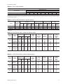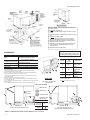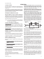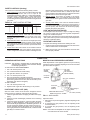
1
SUNLINE PLUS™
GAS / ELECTRIC
SINGLE PACKAGE AIR CONDITIONERS
INSTALLATION INSTRUCTION
035-14832-003-A-0204
Supersedes: 035-14832-002-A-0302
MODELS D2EG 048 & 060 and D3EG 036
(11 SEER)
FOR YOUR SAFETY
Do not store or use gasoline or
other flammable vapors or liquids
in the vicinity of this or any other
appliance.
If you smell gas:
1. Open windows
2. Don't touch electrical switches.
3. Extinguish any open flame.
4. Immediately call your gas supplier.
GENERAL
YORK Model DEG units are single package air conditioners with
gas heat designed for outdoor installation on a rooftop or a slab.
The units are completely assembled on rigid, permanently
attached base rails. All piping, refrigerant charge, and
electrical wiring is factory-installed and tested. The units
require only electric power, gas piping and duct connections
at the point of installation.
The gas-fired heaters have aluminized steel tubular heat
exchangers and spark ignition with intermittent pilot.
This appliance is not to be used for temporary heating of
buildings or structures under construction.
INSPECTION
As soon as a unit is received, it should be inspected for possible
damage during transit. If damage is evident, the extent of the
damage should be noted on the carrier's freight bill. A separate
request for inspection by the carrier's agent should be made in
writing. Refer to Form 50.15-NM for additional information.
REFERENCE
55.70-N1
55.70-N2
530.18-N1.2V
530.18-N1.13V
530.18-N1.14V
530.18-N1.12V
530.18-N1.8V
530.18-N2.11V
530.18-N8.2V
530.18-N8.3V
530.18-N8.4V
530.18-N8.12V
690.15-N25V
-Man. Outdoor Air Damper Accy 0-100%
-Motorized Outdoor Air Damper Accy.
-Coil Guard
-Low NOx Accessory
-High Altitude Accy. (Natural Gas)
-High Altitude Accy. (Propane)
-Gas Piping Accessory
-Propane Conversion Accessory
-Low Ambient Accessory
Renewal Parts:
• Refer to Parts Manual for complete listing of replacement
parts on this equipment.
All forms referenced in this instruction may be ordered from:
Standard Register
Toll Free Tel.: 877-318-9675
Fax: 877-379-7920
APPROVALS
Design certified by CGA and UL listed as follows:
Additional information on the design, installation, operation
and service of this equipment is available in the following
reference forms:
•
•
•
•
•
•
•
•
•
•
•
•
•
-General Installation
-Pre-start & Post-start Check List
-Economizer Accessory
-Man. Outdoor Air Damper Accy 0-35%
1. For use as a forced air furnace with cooling unit.
2. For outdoor installation only.
3. For installation directly on combustible flooring or, in the U.S.A.,
on wood flooring or Class A, B, or C roof covering material.
4. For use with natural gas and/or propane (LP) gas.
Not suitable for use with conventional venting systems.
Installer should pay particular attention to the words: NOTE, CAUTION and WARNING. Notes are intended to clarify or make
the installation easier. Cautions are given to prevent equipment damage. Warnings are given to alert installer that personal injury and/or equipment damage may result if installation procedure is not handled properly.
CAUTION
THIS PRODUCT MUST BE INSTALLED IN STRICT COMPLIANCE WITH THE ENCLOSED INSTALLATION INSTRUCTIONS AND ANY APPLICABLE LOCAL, STATE, AND NATIONAL CODES INCLUDING, BUT NOT LIMITED TO, BUILDING,
ELECTRICAL, AND MECHANICAL CODES
WARNING
INCORRECT INSTALLATION MAY CREATE A CONDITION WHERE THE OPERATION OF THE PRODUCT COULD
CAUSE PERSONAL INJURY, PROPERTY DAMAGE AND/OR DEATH.
WARNING
DE-ENERGIZE THE ELECTRICAL POWER AND TURN OFF THE GAS SUPPLY TO THE UNIT BEFORE ATTEMPTING TO
INSPECT, REPAIR OR PERFORM MAINTENANCE TO THE UNIT.
035-14832-003-A-0204
TABLE OF CONTENTS
MAINTENANCE & TROUBLESHOOTING
General................................................................................1
Inspection ............................................................................1
Reference ............................................................................1
Approvals ............................................................................1
Nomenclature ......................................................................2
Normal Maintenance .........................................................17
Cleaning Flue Passages and Heating Elements ...............17
Troubleshooting ........................................................18 & 19
TABLES
INSTALLATION
No.
1
2
3
4
5
6
7
8
9
10
11
12
13
14
Limitations ...........................................................................3
Location ...............................................................................3
Rigging and Handling ..........................................................3
Clearances ..........................................................................3
Ductwork .............................................................................3
Filters...................................................................................4
Condensate Drain ...............................................................4
Service Access ....................................................................4
Thermostat ..........................................................................4
Power and Control Wiring ...................................................4
Blower Speed Selection ......................................................4
Compressors .......................................................................4
Combustion Discharge ........................................................4
Disconnect Switch Bracket For Optional Belt-Drive ............5
Gas Piping ...........................................................................5
Gas Connection...................................................................6
L.P. Units, Tanks and Piping ................................................6
Low NOx Application ...........................................................6
Vent and Combustion Air Hoods .........................................7
Optional Economizer Rain Hood .........................................7
Description
Page
Unit Application Data..................................
3
Gas Heat Application Data.........................
4
Pipe Sizing .................................................
5
Physical Data .............................................
8
Supply Air Perf. Direct-Drive Units ............
8
Supply Air Perf.3 & 4Ton Belt-Drive Units ..
9
Supply Air Perf.5 Ton Belt-Drive Units ....... 10
Static Resistances...................................... 11
Motor & Drive Data..................................... 11
Electrical Data (Direct-Drive Units) ............ 11
Electrical Data (Belt-Drive Units)................ 11
Limit Control Setting................................... 14
15
Belt-Drive Supply Air Motor Pulley Adj.......
Gas Rate - Cubic Feet Per Hour ................ 16
FIGURES
OPERATION
No.
1
2
3
4
5
6
7
8
9
10
11
12
13
14
15
Cooling System .................................................................13
Preliminary Operation Cooling ..........................................13
Cooling Sequence of Operation ........................................13
Safety Controls (Cooling) ..................................................13
Heating Sequence of Operation ........................................13
Safety Controls (Heating) ................................................. 14
Heat Anticipator Setpoints .................................................14
Pre-Start Check List ..........................................................14
START-UP
Operating Instructions .......................................................14
Post-Start Check List (Gas)...............................................14
Manifold Gas Pressure Adjustment ...................................14
Pilot Checkout ...................................................................15
Burner Instructions ............................................................15
Burner Air Shutter Adjustment...........................................15
Supply Air Blower and Temperature Rise Adj....................15
Supply Air Blower and Temperature Rise Adj. ............15&16
Checking Gas Input ...........................................................16
Secure Owner's Approval..................................................16
Description
Page
Center of Gravity ........................................
3
Recommended Drain Piping ......................
4
Typical Field Wiring ....................................
5
External Supply Connection.......................
6
Bottom Supply Connection.........................
6
Vent and Combustion Air Hoods ................
7
Economizer Rain Hood Assembly..............
7
Enthalpy Setpoint Adjustment ....................
8
Dimensions and Clearances ...................... 12
Gas Valve Piping........................................ 13
Typical Gas Valve....................................... 14
Proper Flame Adjustment .......................... 15
Typical Flame Appearance......................... 15
Belt Adjustment .......................................... 15
Press. Drop versus Supply Air CFM .......... 16
PRODUCT NOMENCLATURE
D
2
E
G
0
3
6
N
0
4
0
2
5
PRODUCT CATEGORY
VOLTAGE CODE
D = Single Package Air Conditioner
(Air Cooled)
06 = 208/230-1-60
25 = 208/230-3-60
46 = 460-3-60
58 = 575-3-60
PRODUCT GENERATION
2 = 2nd Generation
3 = 3rd Generation
NOMINAL GAS HEATING
OUTPUT CAPACITY
PRODUCT IDENTIFIER
EG = High Efficiency Gas/Electric
NOMINAL COOLING
CAPACITY
036 = 3 Ton
048 = 4 Ton
060 = 5 Ton
2
FACTORY INSTALLED HEAT
N = Natural Gas
040 = 40 MBH
060 = 60 MBH
079 = 79 MBH
099 = 99 MBH
Unitary Products Group
035-14832-003-A-0204
INSTALLATION
LIMITATIONS
These units must be installed in accordance with the current
edition of the following national and local safety codes:
In the U.S.A.:
1. National Electrical Code ANSI/NFPA No. 70.
2. National Fuel Gas Code Z223.1.
3. Gas-Fired Central Furnace Standard ANSI Z21.47-1993.
4. Local gas utility requirements.
In Canada:
1. Canadian Electrical Code CSA C22.1
2. Current Gas Installation Codes CAN/CGA-2.3-M93.
3. Local plumbing and waste water codes.
4. Other applicable local codes.
Refer to Table 1 for Unit Application Data and to Table 2 for Gas
Heat Application Data.
If components are to be added to a unit to meet local codes, they
are to be installed at the dealer's and / or the customer's expense.
Size of unit for proposed installation should be based on heat
loss / heat gain calculation made according to the methods of
Air Conditioning Contractors of America (ACCA).
LOCATION
TABLE 1 - UNIT APPLICATION DATA
Model DEG
208/230V
Voltage Variation
460V
Min. / Max.1
575V
Supply Air CFM, Nom.
Wet Bulb Temperature (°F) of
Air on Evaporator Coil,
Min. / Max.
Dry Bulb Temperature (°F) of
Air on Condenser Coil,
Min2 / Max.
036
1200
048
187 / 253
414 / 506
518 / 630
1600
060
2000
57 / 72
57 / 72
57 / 72
45 / 120
45 / 120
45 / 120
1
Utilization range “A” in accordance with ARI Standard 110.
CAUTION: If a unit is to be installed on a roof curb or special
frame other than a YORK roof curb, gasketing
must be applied to all surfaces that come in contact
with the unit underside.
5. Maintain level tolerance to 1/2" maximum across the entire
length or width of the unit.
6. Elevate the unit sufficiently to prevent any blockage of the
air entrances by snow in areas where there will be snow
accumulation. Check the local weather bureau for the
expected snow accumulation in your area.
RIGGING AND HANDLING
Exercise care when moving the unit. Do not remove any
packaging until the unit is near the place of installation. Rig the
unit by attaching chain or cable slings to the lifting holes
provided in the base rails. Spreaders, whose length exceeds
the largest dimension across the unit, MUST be used across
the top of the unit.
BEFORE LIFTING A UNIT, MAKE SURE THAT ITS WEIGHT
IS DISTRIBUTED EQUALLY ON THE CABLES SO THAT IT
WILL LIFT EVENLY.
Units may also be moved or lifted with a forklift. Slotted
openings in the base rails are provided for this purpose.
LENGTH OF FORKS MUST BE A MINIMUM OF 42".
Remove the nesting brackets from the four corners on top of
the unit. All screws that are removed when taking these
brackets off must be replaced on the unit.
CAUTION: An adhesive backed label is provided over the outside of the combustion air inlet opening to prevent
moisture from entering the unit which could cause
damage to electrical components. Allow this closure label to remain in place until the combustion
air hood is to be installed (refer to Figure 6).
Refer to Table 4 for unit weights and to Figure 1 for approximate
center of gravity.
CLEARANCES
CONDENSER
COIL END
BACK
APPROXIMATE
CENTER OF
GRAVITY
2
FRONT
A low ambient accessory is available for operation down to 0°F.
Use the following guidelines to select a suitable location for
these units.
1. Unit is designed for outdoor installation only.
2. Condenser coils must have an unlimited supply of air.
Where a choice of location is possible, position the unit on
either north or east side of building.
WARNING: Excessive exposure of this furnace to contaminated combustion air may result equipment damage or personal injury. Typical contaminates
include: permanent wave solutions, chlorinated
waxes and cleaners, chlorine based swimming
pool chemicals, water softening chemicals, carbon
tetrachloride, Halogen type refrigerants, cleaning
solvents (e.g. perchloroethylene), printing inks,
paint removers, varnishes, hydrochloric acid, cements and glues, antistatic fabric softeners for
clothes dryers, masonry acid washing materials.
3. For ground level installation, a level pad or slab should be
used. The thickness and size of the pad or slab used should
meet local codes and unit weight. Do not tie the slab to the
building foundation.
4. Roof structures must be able to support the weight of the
unit and its options and / or accessories. Unit must be
installed on a solid level roof curb or appropriate angle iron
frame.
Unitary Products Group
% “
30-1/2
44
&
15-1/8
A
30
B
FIG. 1 - CENTER OF GRAVITY
67-3/4
“
82
"
DIM.
A
B
3-5 TON
19-3/4"
40-3/4"
All units require certain clearances for proper operation and
service. Installer must make provisions for adequate
combustion and ventilation air in accordance with Section 5.3,
Air for Combustion and Ventilation of the National Fuel Gas
Code, ANSI Z223.1 (in U.S.A.) or Sections 7.2, 7.3 or 7.4 of
Gas Installation Codes CAN/CGA-B149.1 and .2 (in Canada)
and/or applicable provisions of the local building codes. Refer
to Figure 9 for the clearances required for combustible
construction, servicing, and proper unit operation.
WARNING: Do not permit overhanging structures or shrubs to
obstruct condenser air discharge outlet, combustion air inlet or vent outlet.
DUCTWORK
Ductwork should be designed and sized according to the
methods in Manual Q of the Air Conditioning Contractors of
America (ACCA).
A closed return duct system shall be used. This shall not
preclude use of economizers or outdoor fresh air intake. The
supply and return air duct connections at the unit should be
made with flexible joints to minimize the transmission of noise.
3
035-14832-003-A-0204
The supply and return air duct systems should be designed for the
CFM and static requirements of the job. They should NOT be
sized to match the dimensions of the duct connections on the unit.
CAUTION: When fastening ductwork to the side duct flanges on
the unit, insert the screws through the duct flanges
only. DO NOT insert the screws through the casing.
Outdoor ductwork must be insulated and waterproofed.
Refer to Figure 9 for information concerning side and bottom
supply and return air duct openings.
FILTERS
1" filters are supplied with each unit. 2" replacement filters may
be used with no modification to the filter racks. Filters must
always be installed ahead of the evaporator coil and must be
kept clean or replaced with same size and type. Dirty filters will
reduce the capacity of the unit and will result in frosted coils or
safety shutdown. Minimum filter area and required sizes are
shown in Table 4.
CONDENSATE DRAIN
Plumbing must conform to local codes. Use a sealing compound
on male pipe threads. Install a condensate drain line from the 3/4"
PVC female connection on the unit to spill into an open drain.
NOTE: The condensate drain line MUST be trapped to provide proper drainage. See Figure 2.
ordinances. The unit must be electrically grounded in
accordance with the NEC (as specified above) and/or local
codes.
Voltage tolerances which must be maintained at the
compressor terminals during start-up and running conditions
are indicated on the unit Rating Plate and Table 1.
The internal wiring harness furnished with this unit is an
integral part of a UL design certified unit. Field alteration to
comply with electrical codes should not be required.
A disconnect switch should be field provided for the unit. The
switch must be separate from all other circuits. Refer to Figure
9 for installation location. If any of the wire supplied with the unit
must be replaced, replacement wire must be of the type shown
on the wiring diagram.
Electrical lines must be sized properly to carry the load. USE
COPPER CONDUCTORS ONLY. Each unit must be wired
with a separate branch circuit fed directly from the meter panel
and properly protected.
CAUTION: When connecting electrical power and control wiring to the unit, waterproof type connectors MUST
BE USED so that water or moisture cannot be
drawn into the unit during normal operation. The
above waterproofing conditions will also apply
when installing a field-supplied disconnect switch.
Refer to Figure 3 for typical field wiring and to the appropriate unit
wiring diagram for control circuit and power wiring information.
BLOWER SPEED SELECTION
FIG. 2 - RECOMMENDED DRAIN PIPING
SERVICE ACCESS
Access to all serviceable components is provided by the
following removable panels:
•
•
•
•
•
•
Compressor compartment
Burner compartment
Blower compartment
Main control box
Filter compartment
Motor access (on units with belt-drive option)
Refer to Figure 9 for location of these access panels.
CAUTION: Make sure that all screws are replaced on the unit
to maintain an air-tight seal.
THERMOSTAT
The room thermostat should be located on an inside wall
approximately 56" above the floor where it will not be subject to
drafts, sun exposure, or heat from electrical fixtures or
appliances. Follow manufacturer's instructions enclosed with
thermostat for general installation procedure. Color coded
insulated wires (#18 AWG) should be used to connect
thermostat to unit. See Figure 3 for wiring details.
NOTE: If the unit has an economizer, remove jumper J1 from
terminals 8 and 10 on the relay board to prevent simultaneous operation of the compressor and the
economizer. If you want to energize the compressor
for supplemental cooling during the economizer operation, use a thermostat with two stages of cooling.
POWER AND CONTROL WIRING
Field wiring to the unit must conform to provisions of the National
Electrical Code (NEC) ANSI/NFPA No. 70 and/or local
4
Three blower motor speeds are available on the direct-drive
units. The speed selection for the direct-drive units is
determined by the CFM and ESP requirements of the
applications. All units with belt-drive option have an adjustable
motor pulley to achieve the above conditions.
All direct-drive units with 208/230 voltage are shipped with the
wire labeled #116 connected to the “HIGH” speed tap on the
blower motor. If a lower blower motor speed is desired, this wire
should be moved to the “MED” or “LOW” speed tap on the
motor for the speed desired.
All direct-drive units with 460 and 575 voltage are shipped with
the wire labeled #116 connected to the “HIGH” speed tap on
the blower motor. If the medium speed is required, connect
wire #116 to the “MED” speed tap and the blue motor lead to
the “HIGH” speed tap. If the low speed is required, connect wire
#116 to the “LOW” speed tap, the blue motor lead to the “HIGH”
speed tap and the orange motor lead to the “MED” speed tap.
COMPRESSORS
On some units the compressor is mounted on springs which
have been tightened down for shipment only.
After this unit is installed, back out the compressor bolts until
the sleeve clears the top grommet.
CAUTION: Do Not loosen compressor mounting bolts.
TABLE 2 - GAS HEAT APPLICATION DATA
Input
Capacity,
(Mbh)
50
75
100
125
Output
Capacity,
(Mbh)
40
60
79
99
Available
Gas Rate1
on
(Ft.3/Hr.)
Models
3 Ton
47
4 Ton
70
3/5 Ton
93
4/5 Ton
116
Temp. Rise °F
At Full Input 2
Min.
Max.
15
45
25
55
40/25
70/55
45/35
75/65
NOTE: Gas Heaters are shipped available for natural gas, but can be converted to L.P. with
Kit Model No. 1NP0434. All furnaces meet the latest California seasonal efficiency
requirements.
1Based on 1075 Btu/Ft3.
2The air flow must be adjusted to obtain a temperature rise within the range shown.
COMBUSTION DISCHARGE
The products of combustion are discharged horizontally
through a screened opening on the gas heat access panel.
Unitary Products Group
035-14832-003-A-0204
CONTROL WIRING
COOLING / HEATING (24 VOLT THERMOSTAT)
C O O L IN G /H E A T IN G
T H E R M O S T A T
T E R M IN A L S
T H E R M O S T A T
T E R M IN A L S
(2 4 V O L T T H E R M O S T A T )
1
A D D
J U M P E R
U N IT T E R M IN A L
S T R IP T B 1
R H
A D D
J U M P E R
COOLING / HEATING (ELECTRONIC THERMOSTAT)
R C
R
Y
Y 1
W
U N IT T E R M IN A L
S T R IP T B 1
R H
R
Y 1
Y 2
W 1
3
W 2
G
G
B
B
L E D 1
X
N O T
U S E D
L E D 2
C O M
A 1
A D D
J U M P E R
W 2
N
4
3
A 2
T O R E M O T E S E N S O R
2 T H 0 4 0 7 0 2 2 2 4 IF U S E D
T
G
G
2
W 2
W 1
2 4 V O L T
T R A N S F O R M E R
Y 1
2
Y 2
2 4 V O L T
T R A N S F O R M E R
Y 2
R C
W 1
4
1
T
B
1
R
T
T
S
W
2 4
E
O
H
E
V O
M O
P R
E E
C O
IT H
L T
V E
E V
C O
N D
T W
O
T H
J U
E N
N O
S T
E R M
M P E
T S IM
M IZ E
A G E
S T A G
C O O L IN G
O S T A T
R J 1 F R
U L T A N
R . IF Y
O F C O
E S O F
2 T H
O M
E O U
O U
O L IN
H E A
0 7 7 0 1 0 2 4 .
T E R M IN A L S
S O P E R A T
W A N T T O C
G O R H A V E
T , U S E T H E
IF T H E
8 A N
IO N O
O N T R
A N D
R M O S
N IT
0 O
H E
T H
E C
T 2
H A S
N T H
C O M
E R E
T R IC
T H 0 4
A N E C
E R E L
P R E S
C O N O
H E A T
7 1 0 2 4
O N O M IZ
A Y B O A R
S O R A N D
M IZ E R O
A C C E S S
E R ,
D
1
E L E C T R O N IC P R O G R A M M A B L E T H E R M O S T A T 2 E T 0 4 7 0 0 2 2 4 (IN C L U D E S S U B B A S E )
2
S E C O N D S T A G E C O O L IN G
IS N O T R E Q U IR E D O N U N IT S L E S S E C O N O M IZ E R .
3
S E C O N D S T A G E H E A T IN G
E L E C T R IC H E A T E R .
IS O N L Y R E Q U IR E D O N U N IT S W IT H A T W O
4
R E
P 6
O U
T H
N A
O R Y
/ H E A T IN G (E L E C T R O N IC T H E R M O S T A T )
S IN G L E S T A G E
T H E R M O S T A T
T E R M IN A L S
1
M O
O N
T -P
E R M
V E
U
U T
O
J U M
N IT S
T O
S T A
B E R
W IT
C L O
T S W
J
H
S E
IT
2 F
E C
T H
C H
R O
O N
E
E S
M T
M IZ
O U T
T O
E R
E R
D O
T H
M IN
. T
O R
E S
A L S 4
E R M IN
E C O N
E T -B A
A N D 9 O N J
A L S A 1 A N D
O M IZ E R D A
C K P O S IT IO
S T A G E
U M P E R P L U G C O N N E C T O R
A 2 P R O V ID E A R E L A Y
M P E R S W H E N T H E
N .
U N IT T E R M IN A L
S T R IP T B 1
R H
R
R C
A D D
J U M P E R
U
D 1
F T
O L
E L
T A
Y 1
Y
W
W 1
G
G
B
2 4 V O L T
T R A N S F O R M E R
1
E L
IF
1 0
C O
E C
E C T R
T H IS
O N T
M P R
O N O
O N IC P
U N IT H A
H E R E L
E S S O R
M IZ E R O
R O
S
A Y
A N
N
G
A N
B
D
A
R A
D
O A
T H
S E
M M A
E C O
R D T
E E C
C O N
B L E
N O M
O P R
O N O
D S T
T H E
IZ E R
E V E
M IZ
A G E
R M O
, R E
N T
E R .
O F
S T
M O
S IM
IF
C O
A T
V E
U L
Y O
O L
2 E
J U
T A
U W
IN G
T 0 7
M P
N E O
A N
, U
7 0 1
E R
U S
T T
S E
0 2 4 (
J 1 F R
O P E
C O
T H E R
O
IN C L U
O M T
R A T IO
N T R O
M O S T
D E
E R
N
L T
A T
S S
M IN
O F
H E
2 E
U B B A S E ).
A L S 8 A N D
T H E
T 0 4 7 0 0 2 2 4 .
POWER WIRING
REFER TO THE ELECTRICAL
DATA TO SIZE THE DISCONNECT
SWITCH, THE WIRING AND THE
OVERCURRENT PROTECTION
REFER TO THE ELECTRICAL
DATA TO SIZE THE DISCONNECT
SWITCH, THE WIRING AND THE
OVERCURRENT PROTECTION
FIG. 3 - TYPICAL FIELD WIRING
DISCONNECT SWITCH BRACKET FOR UNITS
WITH OPTIONAL BELT-DRIVE BRACKET
The heating value of the gas may differ with locality. The value
should be checked with the local gas utility.
A special bracket for mounting a field-supplied disconnect
switch is provided in each unit ordered with an optional beltdrive supply air blower. The bracket is shipped inside the
blower compartment taped to the top of the blower housing.
Install the bracket on the left hand side of the unit as shown in
Figure 9. Several existing screws at the top of the unit and one
approximately midway down from the top will be used for
mounting the bracket. Screws should be loosened only - NOT
REMOVED. Mounting holes in the bracket have elongated
keyways allowing easy installation. Re-tighten screws after
bracket is in place to ensure panels will remain leak tight.
NOTE: There may be a local gas utility requirement specifying
a minimum diameter for gas piping. All units require a
1/2 inch pipe connection at the entrance fitting.
GAS PIPING
Proper sizing of gas piping depends on the cubic feet per hour
of gas flow required, specific gravity of the gas and the length of
run. “National Fuel Gas Code” Z223.1 should be followed in all
cases unless superseded by local codes or gas company
requirements. Refer to Table 3.
Unitary Products Group
TABLE 3 - PIPE SIZING
Length in Feet
10
20
30
40
50
60
70
80
90
100
1/2 in.
132
92
73
63
56
50
46
43
40
38
Nominal Iron Pipe Size
3/4 in.
1 in.
278
190
152
130
115
105
96
90
84
79
520
350
285
245
215
195
180
170
160
150
1-1/4 in.
1,050
730
590
500
440
400
370
350
320
305
Maximum capacity of pipe in cubic feet of gas per hour. (Based upon a pressure drop of 0.3 inch
water column and 0.6 specific gravity gas).
5
035-14832-003-A-0204
FIG. 4 - EXTERNAL SUPPLY CONNECTION
EXTERNAL SHUT-OFF
FIG. 5 - BOTTOM SUPPLY CONNECTION
EXTERNAL SHUT-OFF
GAS CONNECTION
The furnace must be isolated from the gas supply piping
system by closing its individual manual shut-off valve
during any pressure testing of the gas supply piping system
at test pressures equal to or less than 1/2 psig (3.48kPa).
7. A 1/8 inch NPT plugged tapping, accessible for test gage
connection, must be installed immediately upstream of the
gas supply connection to the furnace.
The gas supply line can be routed through the knockouts
located on the front of the unit or through the opening provided
in the unit's base. Refer to Figure 9 to locate these access
openings. Typical supply piping arrangements are shown in
Figures 4 and 5. All shaded items are field-supplied.
Two grommets are shipped in the blower compartment (in parts
bag taped to the blower housing) of every unit with gas heat
and should be used in the knockouts when the gas piping
penetrates the front of the unit.
After the gas supply piping has been installed, the bottom
opening should be sealed to prevent water from leaking into the
building.
Gas piping recommendations:
1. A drip leg and a ground joint union must be installed in the
gas piping.
2. When required by local codes, a manual shut-off valve may
have to be installed outside of the unit.
3. Use wrought iron or steel pipe for all gas lines. Pipe
compound should be applied sparingly to male threads
only.
WARNING: Natural gas may contain some propane. Propane,
being an excellent solvent, will quickly dissolve
white lead or most standard commercial compounds. Therefore, a special pipe compound must
be applied when wrought iron or steel pipe is used.
Shellac base compounds such as Gaskolac or
Stalastic, and compounds such as Rectorseal #5,
Cyde's or John Crane may be used.
4. All piping should be cleaned of dirt and scale by hammering
on the outside of the pipe and blowing out the loose dirt and
scale. Before initial start-up, be sure that all of the gas lines
external to the unit have been purged of air.
5. The gas supply should be a separate line and installed in
accordance with all safety codes as prescribed under
“Limitations”. After the gas connections have been
completed, open the main shut-off valve admitting normal
gas pressure to the mains. Check all joints for leaks with
soap solution or other material suitable for the purpose.
NEVER USE A FLAME.
6. The furnace and its individual manual shut-off valve must
be disconnected from the gas supply piping system during
any pressure testing of that system at test pressures in
excess of 1/2 psig (3.48kPa).
6
L.P./PROPANE UNITS, TANKS AND PIPING
All gas heat units are shipped from the factory equipped for
natural gas use only. The unit may be converted in the field for
use with L.P./propane gas with accessory kit model number
1NP0434.
All L.P./propane gas equipment must conform to the safety
standards of the National Fire Protection Association.
For satisfactory operation, L.P./propane gas pressure must be
10.5 inch W.C at the unit under full load. Maintaining proper gas
pressure depends on three main factors:
1. The vaporization rate which depends on (a) the
temperature of the liquid and (b) the “wetted surface” area
of the container or containers.
2. The proper pressure regulation. (Two-stage regulation is
recommended from the standpoint of both cost and
efficiency.)
3. The pressure drop in the lines between regulators and
between the second stage regualtor and the appliance.
Pipe size required will depend on the length of the pipe run
and the total load of all appliances.
Complete information regarding tank sizing for vaporization,
recommended regulator settings, and pipe sizing is available
from most regulator manufacturers and L.P./propane gas
suppliers.
L.P./propane gas is an excellent solvent and special pipe
compound must be used when assembling piping for this gas
as it will quickly dissolve white lead or most standard
commercial compounds. Shellac base compunds such as
Rectorseal #5 are satisfactory for this type of gas.
Check all connections for leaks when piping is completed,
using a soap solution. NEVER USE A FLAME.
LOW NOx APPLICATION
For natural gas heat installations in locations which require low
Nitros Oxide emmissions, accessory model 1LN0404 must be
installed.
Unitary Products Group
035-14832-003-A-0204
VENT AND COMBUSTION AIR HOODS
1. With filter section access panel removed, take out hood
components, filters and sensor described above. Remove
and discard outdoor air opening cover on back unit (Upper
right hand corner).
The vent and combustion air hoods are shipped attached to the
blower housing in the blower compartment. These hoods must
be installed on the outside of the gas heat panel to ensure
proper unit function. The necessary mounting screws are
provided in a bag that is also attached to the blower housing.
The screen for the combustion air intake hood is secured to the
inside of the access panel opening with three fasteners and the
screws used for mounting the hood to the panel. The top flange
of this hood slips in under the top of the access panel opening
when installing. Refer to Figure 6. Remove the protective label
covering the opening just prior to installing this hood.
The vent hood (including its screen) is installed by inserting the
top flange of the hood into the slotted opening in the access
panel. The top screw secures the hood to the access panel.
The remaining two side screws must be installed after the
access panel is installed on the unit. These screws engage the
bottom flue box flange.
2. Remove the 1/2" knockout (A) in the units rear panel
(located to the right side of the outdoor air opening). Insert
the two loose wires from inside the unit, into the 1/2"
bushing provided. Insert wires and bushing into knockout.
Snap bushing into place.
3. Mount the outdoor air sensor to the rear panel, just below
the knockout described in Step 2. Secure with two selfdrilling screws at dimples (B) provided in the panel.
NOTE: Sensor must be positioned so that the sensing ports
are at the top (louvers pointing downward) and terminal connections to the right.
4. Connect the two wires, indicated in Step 2, to the sensor as
follows:
CAUTION: All three screws in the vent hood must be properly
installed before furnace operation to insure all
combustion products are exhausted from the unit.
• Wire #73 to terminal (+)
• Wire #74 to terminal (S)
5. Assemble the LH and RH side plates to the top cover (2
screws each side) to form the hood. Apply gasketing to the
flange surface on each side plate. Extend gasketing 1/4"
beyond top and bottom of each flange to insure adequate
corner sealing. Secure this assembly to the unit back panel
(upper right hand corner). First, remove screw (C) on unit
top cover. Then slip flange of hood cover in under flange of
unit top cover, replace screw (C), engaging hole (E) in hood
flange and tighten. Attach the two side plates to the unit
panel by using two self-drilling screws for each side plate at
dimples (D) provided in the panel.
FIG. 6 - VENT AND COMBUSTION AIR HOODS
OPTIONAL ECONOMIZER RAIN HOOD
6. Position fillpiece at bottom of hood, between the two side
plates but do not secure at this time. (Slotted openings
MUST be downward for drainage). After fillpiece is properly
positioned, note where contact is made with the unit panel.
Remove fillpiece and apply gasket material to this area to
provide a seal. Reposition fillpiece and secure with 2
screws.
The following procedure should be used when assembling an
economizer rain hood onto a unit. Refer to Figure 7. The
outdoor and return air dampers, damper actuator, the linkage
and all the controls are factory mounted as part of the
economizer option.
All of the hood components, including the filters, the gasketing
and the hardware for assembling are located above the top
filter racks within the filter section. The outdoor air sensor is in
the bag of parts located at the bottom of the return air section.
FILTER
COVER
7. Install the two filters into the hood assembly, sliding down
along retainers on side plates, into fillpiece at bottom of
hood.
OUTDOOR AIR
OPENING COVER
HOOD
COVER
C
OUTDOOR AIR
SENSOR
D
E
GASKETED
FLANGE
A
D
B
D
D
GASKET
L. H. SIDE
PLATE
GASKETED
FLANGE
FILTERS
R. H.
SIDE
PLATE
FILTER SECTION
ACCESS PANEL
SIDE DUCT
APPLICATION SHOWN
FILLPIECE
FIG. 7 - ECONOMIZER RAIN HOOD ASSEMBLY (OPTION)
Unitary Products Group
7
035-14832-003-A-0204
NOTE: Install filters so that “Air Flow” arrows point toward the
unit.
8. Install filter cover over the end of the hood with one screw
(center of hood), securing filters into position.
CAUTION: When proceeding with Steps 9 and 10, extreme
care must be exercised while turning both the set
point and minimum position adjusting screws to
prevent twisting them off.
9. The enthalpy set point for the dampers may now be set by
selecting the desired set point from graph in Figure 8. For a
single enthalpy economizer, carefully turn the set point adjusting screw to the “A”, “B”, “C” or “D” setting corresponding to the lettered curve. For a dual enthalpy economizer,
carefully turn the set point adjusting screw fully clockwise
past the “D” setting.
10. To check that the damper blades move smoothly without
binding, carefully turn the minimum position adjusting
screw fully clockwise and then energize and de-energize
terminals “R” to “G”. With terminals “R” to “G” energized,
turn the minimum position screw counterclockwise until the
desired minimum position has been attained.
11. Replace the filter section access panel.
FIG. 8 - ENTHALPY SET POINT ADJUSTMENT
TABLE 4 - PHYSICAL DATA
MODELS
036
12 x 10
DEG
048
12 x 10
060
12 x 10
1
1.5
3
13
5.1
22
CENTRIFUGAL BLOWER (Dia. x Wd. in.)
!
FAN MOTOR HP (Direct-Drive)
"
FAN MOTOR HP (Belt-Drive)
1.5
1.5
ROWS DEEP
3
3
EVAP.
FINS PER INCH
13
13
COIL
FACE AREA (Sq. Ft.)
3.6
4.3
22
22
PROPELLER DIA. (in.)
COND.
FAN MOTOR HP
FAN
4,500
4,200
4,500
NOM. CFM TOTAL
2
2
2
ROWS DEEP
COND.
18
18
18
FINS PER INCH
COIL
17.1
17.1
17.1
FACE AREA (Sq. Ft.)
AIR
QUANTITY PER UNIT (14" x 20" x 1")
2
2
2
FILTERS
QUANTITY PER UNIT (14" X 25" X 1")
1
1
1
TOTAL FACE AREA (sq. ft.)
6.3
6.3
6.3
(SEE NOTE)
CHARGE
REFRIGERANT 22 (lbs./oz.)
9/12
9/8
9/8
COMPRESSOR QUANTITY PER UNIT (HERMETIC TYPE) 1 / RECPT 1 /RECPT 1 / SCROLL
EVAP.
BLOWER
WEIGHTS (LBS)
3 Ton
615
Basic Unit
4 Ton
655
(Nom. Max.)
5 Ton
680
OPTIONS / ACCESSORIES
Economizer
50
Motorized Outdoor
26
Air Damper
Barometric Relief/Fixed
10
Outdoor Air Intake Damper
Roof Mounting Curb
92
Belt-Drive Blower
5
NOTE: Filter racks are adapted for 1" or 2" thick filters.
TABLE 5 - SUPPLY AIR PERFORMANCE - 3, 4, & 5 TON w/Direct-Drive Blower
GAS HEAT VALUES SHOWN @ 230/460/575 VOLTS - Side Duct Connections
MODEL
DEG
036
048
060
MOTOR
SPEED
HI
MED
LOW
HI
MED
LOW
HI
MED
LOW
0.20
CFM Watts
1684 800
1487 710
1996 960
1804 838
1681 760
2400 1155
2290 1105
2150 1020
0.30
CFM Watts
1631 780
1464 690
1933 936
1765 810
1640 738
2338 1125
2214 1065
2100 990
Available External Static Pressure - IWG*
0.40
0.50
0.60
0.70
0.80
CFM Watts CFM Watts CFM Watts CFM Watts CFM Watts
1699 825 1650 785 1570 755 1430 725 1360 700
1582 750 1524 720 1410 690 1324 650 1260 630
1421 670 1367 650 1315 620 1246 605 1185 590
1868 910 1795 880 1722 845 1635 820 1544 790
1714 785 1650 765 1589 735 1508 705 1407 675
1604 715 1541 695 1490 670 1416 645 1337 620
2274 1095 2167 1045 2096 1010 1990 980 1887 945
2145 1030 2071 990 1990 950 1911 920 1828 885
2029 950 1965 910 1905 880 1816 838 1724 800
0.90
CFM Watts
1280 680
1185 610
1110 570
1419 765
1306 645
1230 595
1771 905
1724 835
1644 770
1.00
CFM Watts
1180 655
1100 590
1020 545
1300 740
1195 625
1120 575
1629 855
1604 798
1531 710
NOTE: FOR 208 VOLTS, MULTIPLY VALUES BY 0.95.
*INCLUDES ALLOWANCES FOR A WET EVAPORATOR COIL, 1" FILTERS, AND THE GAS-FIRED HEAT EXCHANGERS. REFER TO TABLE 8 FOR RESISTANCE VALUES
ON APPLICATIONS OTHER THAN GAS/ELECTRIC UNITS WITH SIDE DUCT AIRFLOWS.
8
Unitary Products Group
035-14832-003-A-0204
TABLE 6 - SUPPLY AIR PERFORMANCE - 3 & 4 Ton w/Belt-Drive Blower
3TON - SIDE DUCT CONNECTIONS @ 230/460/575 Volts
MODEL AIR FLOW
DEG
CFM
036
2000
1900
1800
1700
1600
1500
1400
1300
1200
MODEL AIR FLOW
DEG
CFM
036
2000
1900
1800
1700
1600
1500
1400
1300
1200
0.20
RPM Watts
843
860
817
775
790
700
-
0.30
RPM Watts
880
925
854
850
828
760
802
670
-
Available External Static Pressure - IWG*
0.40
0.50
0.60
RPM Watts RPM Watts RPM Watts
919
1005
956
1065
993
1145
893
920
930
995
970
1065
867
840
906
905
944
980
840
745
881
815
920
900
818
665
858
740
898
820
842
695
882
755
833
650
867
705
858
665
847
640
0.70
RPM Watts
1030
1195
1008
1125
985
1040
961
970
940
890
922
835
904
765
893
725
880
680
0.80
RPM Watts
1067
1235
1046
1170
1025
1100
1001
1030
980
950
962
895
942
820
932
785
916
730
0.90
RPM Watts
1103
1270
1085
1210
1064
1145
1040
1075
1020
1005
1003
945
982
880
970
835
953
780
1.00
RPM Watts
1102
1180
1081
1115
1060
1050
1044
995
1024
920
1010
870
992
815
Available External Static Pressure - IWG*
1.10
1.20
1.30
RPM Watts RPM Watts RPM Watts
1121
1140
1100
1085
1086
1035
1067
965
1107
1000
1053
920
1099
960
1034
855
1080
905
-
1.40
RPM Watts
-
1.50
RPM Watts
-
4 TON - SIDE DUCT CONNECTIONS @ 230/460/575 Volts
MODEL AIR FLOW
DEG
CFM
048
2000
1900
1800
1700
1600
1500
1400
1300
1200
MODEL AIR FLOW
DEG
CFM
048
2000
1900
1800
1700
1600
1500
1400
1300
1200
0.20
RPM Watts
843
860
817
775
790
700
-
0.30
RPM Watts
880
925
854
850
828
760
802
670
-
Available External Static Pressure - IWG*
0.40
0.50
0.60
RPM Watts RPM Watts RPM Watts
919
1005
956
1065
993
1145
893
920
930
995
970
1065
867
840
906
905
944
980
840
745
881
815
920
900
818
665
858
740
898
820
842
695
882
755
833
650
867
705
858
665
847
640
0.70
RPM Watts
1030
1195
1008
1125
985
1040
961
970
940
890
922
835
904
765
893
725
880
680
0.80
RPM Watts
1067
1235
1046
1170
1025
1100
1001
1030
980
950
962
895
942
820
932
785
916
730
0.90
RPM Watts
1103
1270
1085
1210
1064
1145
1040
1075
1020
1005
1003
945
982
880
970
835
953
780
1.00
RPM Watts
1102
1180
1081
1115
1060
1050
1044
995
1024
920
1010
870
992
815
Available External Static Pressure - IWG*
1.10
1.20
1.30
RPM Watts RPM Watts RPM Watts
1121
1140
1100
1085
1086
1035
1067
965
1107
1000
1053
920
1099
960
1034
855
1080
905
-
1.40
RPM Watts
-
1.50
RPM Watts
-
NOTE: FOR 208 VOLTS, MULTIPLY VALUES BY 0.95.
*INCLUDES ALLOWANCES FOR A WET EVAPORATOR COIL, 1" FILTERS, AND THE GAS-FIRED HEAT EXCHANGERS. REFER TO TABLE 8 FOR RESISTANCE VALUES
ON APPLICATIONS OTHER THAN GAS / ELECTRIC UNITS WITH SIDE DUCT AIRFLOWS.
Unitary Products Group
9
035-14832-003-A-0204
TABLE 7 - SUPPLY AIR PERFORMANCE - 5 Ton w/Belt-Drive Blower
5 TON - SIDE DUCT CONNECTIONS @230/460/575 Volts
MODEL AIR FLOW
DEG
CFM
060
2500
2400
2300
2200
2100
2000
1900
1800
1700
1600
1500
MODEL AIR FLOW
DEG
CFM
060
2500
2400
2300
2200
2100
2000
1900
1800
1700
1600
1500
0.20
RPM Watts
1059
1560
1032
1405
1005
1260
980
1160
930
1060
877
950
-
0.30
RPM Watts
1077
1590
1054
1470
1024
1275
1002
1170
957
1070
908
975
-
Available External Static Pressure - IWG*
0.40
0.50
0.60
RPM Watts RPM Watts RPM Watts
1095
1630
1114
1650
1134
1660
1074
1525
1094
1560
1116
1595
1049
1370
1069
1440
1090
1475
1022
1190
1044
1250
1066
1350
983
1080
1010
1100
1039
1160
941
1000
976
1020
1009
1050
894
885
940
940
980
980
855
815
903
860
950
905
884
815
925
850
864
770
908
805
882
740
0.70
RPM Watts
1158
1685
1140
1620
1116
1505
1090
1410
1064
1260
1040
1100
1014
1020
988
940
964
880
948
835
926
780
0.80
RPM Watts
1181
1720
1167
1640
1142
1535
1117
1440
1092
1340
1070
1225
1047
1095
1022
970
1001
910
987
870
965
830
0.90
RPM Watts
1193
1665
1170
1580
1148
1480
1121
1385
1100
1285
1079
1180
1058
1060
1035
960
1020
900
1004
860
1.00
RPM Watts
1202
1620
1180
1530
1155
1425
1133
1340
1110
1240
1090
1135
1071
1030
1056
965
1038
880
Available External Static Pressure - IWG*
1.10
1.20
1.30
RPM Watts RPM Watts RPM Watts
1190
1475
1169
1385
1205
1445
1143
1280
1178
1330
1222
1375
1122
1190
1158
1240
1196
1295
1103
1100
1134
1140
1164
1175
1088
1035
1118
1065
1145
1105
1070
925
1101
980
1130
1045
1.40
RPM Watts
1197
1205
1170
1130
1158
1075
1.50
RPM Watts
1198
1150
1184
1110
NOTE: FOR 208 VOLTS, MULTIPLY VALUES BY 0.95.
*INCLUDES ALLOWANCES FOR A WET EVAPORATOR COIL, 1" FILTERS, AND THE GAS-FIRED HEAT EXCHANGERS. REFER TO TABLE 8 FOR RESISTANCE VALUES
ON APPLICATIONS OTHER THAN GAS / ELECTRIC UNITS WITH SIDE DUCT AIRFLOWS.
10
Unitary Products Group
035-14832-003-A-0204
TABLE 8 - STATIC RESISTANCES
EXTERNAL STATIC PRESSURE DROP
RESISTANCE, IWG
CFM
1000
1200
1400
1600
1800
2000
0.07
0.08
0.09
0.11
0.13
0.15
0.06
0.07
0.08
0.09
0.10
0.11
DESCRIPTION
Economizer1, 2
Bottom Duct Connections1
2200
0.17
0.12
2400
0.20
0.14
2600
0.23
0.16
1
Deduct these resistance values from the available external static pressure shown in the respective Blower Performance Table.
2
The pressure thru the economizer is greater for 100% outdoor air than for 100% return air. If the resistance of the return air duct system is less than 0.25 IWG, the unit will deliver less CFM
during full economizer operation.
TABLE 9 - MOTOR AND DRIVE DATA - Belt-Drive Blower
MOTOR*
MODEL
BLOWER
RANGE
(RPM)
HP
RPM
FRAME
SIZE
DEG 036
DEG 048
DEG 060
790 - 1120
790 - 1120
850 - 1220
1-1/2
1-1/2
1-1/2
1725
1725
1725
56
56
56
ADJUSTABLE
MOTOR PULLEY
PITCH
SERVICE
BORE
DIA.
FACTOR
(in.)
(in.)
1.15
2.4 - 3.4
7/8
1.15
2.4 - 3.4
7/8
1.15
2.4 - 3.4
7/8
FIXED
BLOWER PULLEY
PITCH
BORE
DIA.
(in.)
(in.)
3.7
1
5.7
1
5.2
1
BELT
PITCH
LENGTH
(in.)
37.3
37.3
37.3
DESIGNATION
A36
A36
A36
*All motors have solid bases and are inherently protected. These motors can be selected to operate into their service factor because they are located in the moving air, upstream of any
heating device.
TABLE 10 - ELECTRICAL DATA - w/Direct-Drive Blower Motor
MODEL
DEG
036
048
060
POWER
SUPPLY
208/230-1-60
208/230-3-60
460-3-60
575-3-60
208/230-1-60
208/230-3-60
460-3-60
575-3-60
208/230-1-60
208/230-3-60
460-3-60
575-3-60
VOLTAGE
LIMITATIONS COMPRESSOR
MIN.
MAX.
RLA
LRA
COND.
FAN
MOTOR,
FLA
187
187
414
518
187
187
414
518
187
187
414
518
253
253
504
630
253
253
504
630
253
253
504
630
16.7
13.1
6.7
5.1
18.7
11.9
6.3
4.9
32.1
19.3
10.0
7.9
87
110
54
44
135
130
64
52.0
135
150
73
50
2.3
2.3
1.4
1.4
2.3
2.3
1.4
1.4
2.3
2.3
1.4
1.4
(SEE NOTE 1)
NOTES: 1. Utilization Range “A” in accordance with ARI Standard 110.
SUPPLY
AIR
BLOWER
MOTOR,
FLA
4.4
4.4
2.0
2.2
5.0
5.0
2.2
2.2
6.6
6.6
3.3
3.3
MINIMUM
CIRCUIT
AMPACITY
27.5
23.1
12.0
10.7
38.6
25.7
13.2
11.4
49.0
33.0
17.2
14.6
MAX.
FUSE
SIZE,
(SEE NOTE 2)
AMPS
40
35
15
15
60
40
20
15
80
50
25
20
MAX.
HACR
BREAKER
SIZE,
AMPS
40
35
15
15
60
40
20
15
80
50
25
20
2. Dual element, time delay type.
TABLE 11 - ELECTRICAL DATA - w/Belt-DriveBlower Motor
MODEL
DEG
036
048
060
POWER
SUPPLY
208/230-1-60
208/230-3-60
460-3-60
575-3-60
208/230-1-60
208/230-3-60
460-3-60
575-3-60
208/230-1-60
208/230-3-60
460-3-60
575-3-60
VOLTAGE
LIMITATIONS COMPRESSOR
MIN.
MAX.
RLA
LRA
COND.
FAN
MOTOR,
FLA
187
187
414
518
187
187
414
518
187
187
414
518
253
253
504
630
253
253
504
630
253
253
504
630
16.7
13.1
6.7
5.1
18.7
11.9
6.3
4.9
32.1
19.3
10.0
7.9
87
110
54
44
135.0
130.0
64.8
52.0
169
123
62
50
2.3
2.3
1.4
1.4
2.3
2.3
1.4
1.4
2.3
2.3
1.4
1.4
(SEE NOTE 1)
NOTES: 1. Utilization Range “A” in accordance with ARI Standard 110.
Unitary Products Group
SUPPLY
AIR
BLOWER
MOTOR,
FLA
7.6
5.3
2.6
2.0
8.6
5.2
2.6
2.0
8.6
6.0
3.0
2.4
MINIMUM
CIRCUIT
AMPACITY
30.7
23.9
12.4
9.8
42.6
26.3
14.3
11.4
51.0
32.4
16.9
13.7
MAX.
FUSE
SIZE,
(SEE NOTE 2)
AMPS
45
35
20
15
60
40
20
15
80
50
25
20
MAX.
HACR
BREAKER
SIZE,
AMPS
45
35
20
15
60
40
20
15
80
50
25
20
2. Dual element, time delay type.
11
035-14832-003-A-0204
(Direct Drive Units)
DUCT COVERS - Units are shipped with all air duct
openings covered.
For side duct applications;
1. Remove and discard the supply and return air duct
covers.
2. Connect ductwork to duct flanges on the rear of the
unit.
For bottom duct applications;
1. Remove the side supply air duct cover to gain
access to the bottom supply air knockout panel.
2. Remove and discard the bottom knockout panel.
3. Replace the side duct cover.
4. With filter section access panel removed from the
unit, remove and discard the bottom return air
knockout panel.
5. Replace the filter access panel.
All dimensions are in inches. They are
subject to change without notice. Certified dimensions will be provided upon
CLEARANCES
Front
Back
Left Side (Filter Access)
Right Side (Cond. Coil)
Below Unit1
Above Unit2
32"
12" (Less Economizer)
36" (With Economizer or Fixed
Air/motorized Air Damper)
24" (Less Economizer)
36" (With Economizer)
24"
20"
72" (For Condenser Air Discharge)
UTILITIES ENTRY DATA
11 3
11 4 #&
1 Units may be installed on combustible floors made from wood or class A, B or C
roof covering material.
2 Units must be installed oudoors. Overhanging structures or shrubs should not
obstruct the outdoor coil nor the fan outlet.
NOTE: A 1" clearance must be provided between any combustible material and the
supply air ductwork for a distance of 3 feet from the unit.
The products of combustion must not be allowed to accumulate within a confined
space and recirculate.
Locate unit so that the vent air outlet hood is at least:
• Three (3) feet above any forced air inlet located within 10 horizontal feet (excluding
those integral to the unit).
• Four (4) feet below, 4 horizontal feet from, or 1 foot above any door or gravity air inlet
into the building.
• Four (4) feet from electric meters, gas meters, regulators and relief equipment.
17 17 7 %&
6
HOLE
KNOCKOUT
SIZE
(DIA.)
A
7/8" *
B
2" *
C
1-5/8"
D
1-1/2"
USED FOR
Control Wiring
(Side or Bottom)**
Power Wiring
(Side or Bottom)
Gas Piping
(Front)
Gas Piping
(Bottom)
*Knockouts in the bottom of the unit can be located by
REAR VIEW
the slice in the insulation.
SIDE SUPPLY AND RETURN
AIR OPENINGS
**Do not remove the 2" knockout ring.
AIR FLOW LEGEND
RETURN AIR
! “ CONDENSATE
"
DRAIN
(must be trapped)
27 19 !"
SUPPLY AIR
30 % &
10 "
OUTDOOR AIR
OUTDOOR AIR
(Economizer)
B
19 &
3
A
8 "
DIMENSION “A”
44 % &
19 DETAIL “A”
UNIT WITH ECONOMIZER RAIN HOOD
FIXED
OUTDOOR
AIR DAMPER
12
MOTORIZED
DAMPER
$ “A”
44 % &
DETAIL “B”
4 !&
UNIT WITH FIXED OUTDOOR
AIR/MOTORIZED DAMPER RAIN HOOD
FIG. 9 - DIMENSIONS AND CLEARANCES (3, 4 & 5 TON)
12
Unitary Products Group
035-14832-003-A-0204
COOLING SYSTEM
OPERATION
The cooling section is a complete factory package utilizing an
air-cooled condenser. The system is factory-charged with
Refrigerant-22.
The compressor is hermetically sealed and internally sprung.
The compressors have inherent (internal) protection. If there is
an abnormal temperature rise in the compressor, the protector
will open to shut down the compressor.
PRELIMINARY OPERATION COOLING
After the installation has been completed, energize the
crankcase heater (3 ton only) for at least 4 hours before
operating the unit. After this initial warm-up, the compressor
should be given three false starts (energized just long enough
to make a few revolutions) with a 5 minute delay between each
start before being put into full time service.
NOTE: Prior to each cooling season, the crankcase heater (3
ton only) must be energized at least 10 hours before
the system is put into operation.
COOLING SEQUENCE OF OPERATION
Single-Stage Cooling: When the thermostat calls for “cooling”,
“R” is closed to “G” and “Y1" (wiring schematic) which
completes the low voltage control circuit, immediately
energizing the compressor, condenser fan motor and blower
motor simultaneously.
Two-Stage Cooling: A two-stage cooling thermostat may be
used if the unit has an economizer. First-stage cooling is
provided by the economizer - if the outdoor air enthalpy is
acceptable, and second-stage cooling is provided by the
compressor. Jumper wire J1 must be removed. Refer to the
unit wiring diagram.
After the thermostat is satisfied and opens, the blower will
continue to run for a short time. All other components will stop.
CONTINUOUS BLOWER - Continuous blower operation is
possible by closing the R to G circuit on the thermostat.
SAFETY CONTROLS (Cooling)
The refrigerant system is equipped wth the following safety
controls:
1. A Suction Line Freezestat to protect against low evaporator temperature due to low air flow or a low return air temperature.
2. A High Pressure Cutout Switch to protect against excessive
discharge pressures due to a blocked condenser coil or a
condenser motor failure.
3. A Low Pressure Switch to protect against loss of refrigerant
charge.
If neither one of the above safety controls opens, the refrigerant
system will be locked out. The lock out of the system can be
reset by opening the 24V circuit either at the room thermostat
or at the unit disconnect.
HEATING SEQUENCE OF OPERATION
The following sequence describes the operation of the gas
heat section.
Unitary Products Group
CONTINUOUS BLOWER: With the room thermostat switch
set to “ON”, the supply air blower will operate continuously. The
normally closed blower interlock relay contact “K3-1" provides
24 volt power to the blower relay ”BR". The “BR” power
contacts close and the blower motor operates.
INTERMITTENT BLOWER: With the room thermostat system
switch set to the “AUTO” or “HEAT” position and the fan switch
set to “AUTO”, the supply air blower will operate after the room
thermostat calls for heat and the air in the gas heat
compartment has achieved a pre-set temeprature.
When “TH1" on the thermostat closes, the draft motor relay
”DMR" or “DMC” is energized. The “DMR” or “DMC” power
contacts close which energizes the line voltage draft motor. As
the speed of the draft motor reaches approximately 2500 RPM,
the centrifugal switch contact “CS” located on the end of the
draft motor shaft closes to power the ignition control “IC”.
After 15 seconds the “IC” will start the ignitor sparking and will
open the redundant valve locted inside the main gas valve
“GV” to allow a flow of gas to only the carryover tube. See
Figure 10. Only after the pilot flame has been ignited and the
presence of pilot flame detected at the “IC” by a signal sent
back through the flame sensor is sparking terminated and the
main gas valve opened.
REDUNDANT
VALVE
MAIN VALVE
GAS MAIN
GAS
VALVE
TO PILOT BURNER
TO MAIN
BURNER
FIG. 10 - GAS VALVE PIPING
Gas flows into each of the main burners and is ignited from the
carryover tube flame.
The “IC” will try for 85 seconds to ignite the pilot carryover tube.
If the “IC” fails to detect a pilot flame during the 85 seconds, it
will close the redundant valve. After a 5 minute purge period,
the “IC” will again try to light the pilot carryover tube. This will
continue continuously until the “IC” detects a pilot flame.
If, after detecting a pilot flame and opening the main gas valve,
the “IC” looses pilot flame indication, it will close both the main
and redundant gas valves. The “IC” will start the above
sequence over until a pilot flame is detected and it will open the
main gas valve again.
The “IC” will only allow 16 pilot flameouts and a single rollout
switch opening per thermostat cycle. After 16 pilot flameouts or
a single rollout switch opening, the “IC” closes both the main
and redundant gas valves. The “IC” requires resetting the
thermostat or removal of it's power lead coming from the draft
motor to reset the “IC” and return it to the above sequence of
operation.
At the same time power was supplied to the “DMR” or “DMC”, a
parallel circuit activates the time delay relay “BT” or “ETD”. The
“BT” or “ETD” closes in approximetly 35 seconds and starts the
circulating air blower by energizing the blower interlock relay
“K3", thus closing the ”K3-2" contact and energizing the blower
relay “BR”.
When the heating cycle is complete, “TH-1" opens deenergizing the “IC”, thus closing the redundant and main gas
valves. The blower motor and the draft motor continue to run
for a short period after the furnace is shut down until the “BT” or
“ETD” opens (in approximately 25 seconds) de-energizing the
“K3", ”BR" and “DMR” or “DMC” relays.
13
035-14832-003-A-0204
SAFETY CONTROLS (Heating)
The control circuit includes the following safety controls:
1. Limit Control (LS). This control is located inside the heat
exchanger compartment and is set to open at the
temperature indicated in Table 12. It resets automatically.
The limit switch, operates when a high temperature
condition, caused by inadequate supply air flow occurs,
thus shutting down the ignition control and closing the main
gas valve.
pilot flame has ignited properly, the main gas valve will not
open. If the flame sensor fails to detect the pilot flame
during operation of the main burners, a signal is sent to the
ignition control to close the main gas valve.
5. Rollout Switch. This switch is located in the burner
vestibule. In the event of a sustained main burner flame
rollout, it shuts off the ignition control and closes the main
gas valve.
TABLE 12 - LIMIT CONTROL SETTING
6. Auxiliary Limit Switch. This control is located inside the
heat exchanger compartment and is set to open at 180°F. It
is a manual reset switch. If the auxiliary limit switch trips,
then the primary limit switch has not functioned properly.
Replace the primary limit switch.
Units
(Tons)
3
4
3
4
5
5
Capacity, MBH
Input
50
75
100
125
100
125
Output
40
60
79
99
79
99
Limit Control
Opens, °F
165
165
165
165
165
165
2. Centrifugal Switch (CS-36). If the draft motor should fail,
the centrifugal switch attached to the shaft of the motor
prevents the ignition control and gas valve from being
energized.
3. Redundant Gas Valve. This valve is an integral part of the
main gas valve and is located up stream of the main gas
valve. Should the main gas valve fail in the open position
the redundant valve serves as a back up and shuts off the
flow of gas.
4. Flame Sensor Rod. This sensor rod is located on the far
side of the carryover tube. If the ignition control does not
receive a signal from the flame sensor indicating that the
HEAT ANTICIPATOR SETPOINTS
The anticipator must be set at 0.1 amps. Too high of a setting
will result in longer heat cycles and a greater temperature
swing in the conditioned space.
Reducing the value below the correct setpoint will give shorter
“ON” cycles and may result in the lowering of the temperature
within the conditioned space.
PRE-START CHECK LIST
Complete the following checks before starting the unit.
1. Check the type of gas being supplied. Be sure that it is the
same as listed on the unit nameplate.
2. Make sure that the vent and combustion air hoods have
been properly installed.
START-UP
OPERATING INSTRUCTIONS
MANIFOLD GAS PRESSURE ADJUSTMENT
CAUTION: This furnace is equipped with an intermittent pilot
and automatic re-ignition system. DO NOT attempt
to manually light the pilot.
Small adjustments to the high-fire gas flow may be made by
turning the pressure regulator adjusting screw on the automatic
gas valve. Refer to Figure 11.
TO LIGHT PILOT AND MAIN BURNERS:
1. Turn “off” electric power to unit.
2. Turn room thermostat to lowest setting.
3. Turn gas valve knob to “on” position.
4. Turn “on” electric power to unit.
5. Set room thermostat to desired temperature.
(If thermostat “set” temperature is above room temperature,
pilot burner ignition will occur and, after an interval to prove
pilot flame, main burners will ignite).
TO SHUT DOWN:
1. Turn “off” electric power to unit.
2. Depress knob of gas valve while turning to “off” position.
POST-START CHECK LIST (GAS)
After the entire control circuit has been energized and the
heating section is operating, make the following checks:
1. Check for gas leaks in the unit piping as well as the supply
piping.
2. Check for correct manifold gas pressures. See “Checking
Gas Input”.
3. Check the supply gas pressure. It must be within the limits
shown on rating nameplate. Supply pressure should be
checked with all gas appliances in the building at full fire. At
no time should the standby gas line pressure exceed 13",
nor the operating pressure drop below 4.5" for natural gas
units. If gas pressure is outside these limits, contact the local
gas utility for corrective action.
14
“ON”-"OFF"
CONTROL
HIGH FIRE ADJ.
(UNDER SCREW)
PILOT ADJ.
(UNDER
SCREW)
Honeywell
VR8204M
“ON”-"OFF" CONTROL
PILOT ADJ.
(UNDER
SCREW)
PRESSURE REGULATOR
MANIFOLD ADJUST. SCREW
White-Rodgers
36E36
1/2-14 NPT (OUTLET)
FIG. 11 - GAS VALVES
Adjust as follows:
1. Remove the cap on the regulator. (High Fire adjusting screw
on valve).
2. To decrease the gas pressure, turn the adjusting screw
counterclockwise.
3. To increase the gas pressure, turn the adjusting screw
clockwise.
NOTE: Check the unit dataplate for the proper manifold pressure and orifice size of the furnace.
Unitary Products Group
035-14832-003-A-0204
PILOT CHECKOUT
The pilot flame should envelope 3/8 inches of the end of the
flame sensor. Refer to Figure 12. To adjust pilot flame, (1)
remove pilot adjustment cover screw, (2) adjust the screw for
the proper pilot flame, (3) be sure to replace cover screw after
adjustment to prevent possible gas leakage.
Knowing the required blower RPM and the blower motor HP,
the speed setting for the supply air motor can be determined.
The setting (turns open) for the optional belt-drive supply air
motor pulley can be determined from Table 13.
TABLE 13 - BELT-DRIVE SUPPLY AIR
MOTOR PULLEY ADJUSTMENT
TURNS
OPEN*
5
4
3
2
1
0
BLOWER DRIVE RANGE (RPM)
3 TON
4 TON
5 TON
850
790
780
924
856
842
998
922
904
1072
988
966
1246
1054
1028
1220
1120
1090
*Pulley can be adjusted in half-turn increments.
FIG. 12 - PROPER FLAME ADJUSTMENT
Put the system into operation and observe through complete
cycle to be sure all controls function properly.
BURNER INSTRUCTIONS
To check or change burners, pilot or orifices, CLOSE MAIN
MANUAL SHUT-OFF VALVE AND SHUT OFF ALL POWER
TO THE UNIT.
1. Remove the two screws holding either end of the manifold
to the burner supports.
2. Open the union fitting in the gas supply line just upstream of
the unit gas valve and downstream from the main manual
shut-off valve.
3. Remove the gas piping patch plate.
4. Disconnect wiring to the gas valve and spark ignitor.
Remove the manifold-burner gas valve assembly by lifting
up and pulling back.
OPTIONAL BELT-DRIVE BLOWER
All units with belt-drive blowers have single speed motors. The
variable pitch pulley on the blower motor can be adjusted to
obtain the desired supply air CFM. Refer to Table 9 for blower
motor and drive data. The tension on the belts should be
adjusted as shown in Figure 14.
CAUTION
Procedure for adjusting belt tension:
1. Loosen nut (D) from the motor mount.
2. Never loosen nuts (C) from each other while loosening nut (D).
3. Adjust the tension by turning bolt (B).
4. Do not loosen the four nuts (top and bottom) (A); unless additional tensioning
distance is required; immediately re-tighten these bolts if loosened.
5. Use a belt tension checker to apply a perpendicular force to one belt at the
midpoint of the span as shown. The deflection force should be applied
until a specific deflection distance of 4mm (5/32")is obtained. To determine
the deflection distance from normal position, use a straight edge from
sheave to sheave as a reference line. The recommended deflection force
is as follows:
H
LENGT
SPAN
ORCE
DEFL F
Burners are now accessible for service.
Reverse the above procedure to replace the assembly. Make
sure that burners are level and seat at the rear of the heat
exchanger.
BURNER AIR SHUTTER ADJUSTMENT
Adjust burner shutters so that a distinct, sharp, blue flame is
obtained. Refer to Figure 13.
(A)
(D)
(C)*
(B)
* NEVER LOOSEN
Tension new belts at the max. deflection force recommended for the belt
section. Check the belt tension at least two times during the first 24 hours of
operation. Any re-tensioning should fall between the min. and max.
deflection force values.
6. After adjusting, re-tighten nut (D) against the motor mount taking care not
to loosen nuts (C).
FIG. 14 - BELT ADJUSTMENT
FIG. 13 - TYPICAL FLAME APPEARANCE
SUPPLY AIR AIR BLOWER AND TEMPERATURE
RISE ADJUSTMENTS
The speed of the supply air blower will depend on the required
CFM, the unit accessories and the static resistances of both the
supply and the return air duct systems. With this information,
the speed for the supply air blower can be determined from the
blower performance and accessory static resistance data in
Table 5 through 8.
Unitary Products Group
Start the supply air blower motor. Adjust the resistances in both
the supply and the return air duct systems to balance the air
distribution throughout the conditioned space. The job
specifications may require that this balancing be done by
someone other than the equipment installer.
To check the supply air CFM after the initial balancing has been
completed:
1. Remove the (two) # $" dot plugs from the holes located on
the filter access panel side of the unit.
2. Insert at least 8" of 1/4 inch tubing into each of these holes
for sufficient penetration into the air flow on both sides of
the evaporator coil.
15
035-14832-003-A-0204
NOTE: The tubes must be inserted and held in a position perpendicular to the air flow so that velocity pressure will
not affect the static pressure readings.
CHECKING GAS INPUT
3. Using an inclined manometer, determine the pressure drop
across a dry evaporator coil. Since the moisture on an
evaporator coil may vary greatly, measuring the pressure
drop across a wet coil under field conditions would be inaccurate. To assure a dry coil, the compressors should be deenergized while the test is being run.
1. Turn off all other gas appliances connected to the gas meter.
0.7
PRESSURE DROP (IWG)
0.6
048
036
2. With the furnace turned on, measure the time needed for
one revolution of the hand on the smallest dial on the meter.
A typical gas meter usually has a 1/2 or a 1 cubic foot test
dial.
3. Using the number of seconds for each revolution and the
size of the test dial increment, find the cubic feet of gas consumed per hour from Table 14.
060
0.5
NATURAL GAS
If the actual input is not within 5% of the furnace rating (with
allowance being made for the permissible range of the
regulator setting) replace the orifice spuds with spuds of
the proper size.
0.4
0.3
NOTE To find the Btu input, multiply the number of cubic feet of
gas consumed per hour by the Btu content of the gas in
your particular locality (contact your gas company for this
information - it varies widely from city to city.)
0.2
0.1
0
750
1250
1750
2250
2750
3250
3750
NOMINAL CFM
FIG. 15 - PRESSURE DROP ACROSS A DRY
EVAPORATOR COIL VS SUPPLY AIR CFM,
WITHOUT AIR FILTERS
4. Knowing the pressure drop across a dry coil, the actual
CFM through the unit can be determined from the curve in
Figure 15.
The temperature rise (or temperature difference between the
return air and the heated air from the furnace) must lie within the
range shown on the UL rating plate and the data in Table 2.
CFM =
BtuhInput x 0.8
108
. x oF Temp. Rise
If the CFM is above or below the specified value, the supply air
motor speed may have to be changed by moving the motor
speed tap to another terminal.
WARNING: Failure to properly adjust the total system air quantity can result in poor system performance.
5. After readings have been obtained, remove the tubes and
seal the holes with the 5/16" dot plugs removed in Step 1.
NOTE: DE-ENERGIZE THE COMPRESSOR BEFORE TAKING ANY TEST MEASUREMENTS TO ASSURE A
DRY INDOOR COIL.
TABLE 14 - GAS RATE - CUBIC FEET PER HOUR
Size of Test Dial
Seconds
for One
Rev.
1/2 cu. ft.
1 cu. ft.
10
12
14
16
18
20
22
24
26
28
30
32
34
36
38
40
42
44
46
48
50
52
54
56
58
60
180
150
129
113
100
90
82
75
69
64
60
56
53
50
47
45
43
41
39
37
36
35
34
32
31
30
360
300
257
225
200
180
164
150
138
129
120
113
106
100
95
90
86
82
78
75
72
69
67
64
62
60
Example: By actual measurement, it takes 38 seconds for the hand on the 1-
cubic foot dial to make a revolution with just a 100,000 Btuh furnace running.
Using this information, locate 38 seconds in the first column in the table above.
Read across to the column headed “1 Cubic Foot”, where you will see that 95
cubic feet of gas per hour are consumed by the furnace at that rate. Multiply 95
x 1050 (the Btu rating of the gas obtained from the local gas company). The result is 99,750 Btuh, which is close to the 100,000 Btuh rating of the furnace.
SECURE OWNER'S APPROVAL: When the system is functioning properly, secure the owner's approval. Show him the location of all disconnect switches and the thermostat. Teach him how to start and stop the unit and how to adjust temperature
settings within the limitations of the system.
16
Unitary Products Group
035-14832-003-A-0204
MAINTENANCE
NORMAL MAINTENANCE
CAUTION: Prior to any of the following maintenance procedures, shut off all power to the unit to prevent personal injury.
Periodic maintenance normally consists of changing or cleaning
filters and (under some conditions) cleaning the main burners.
FILTERS - Inspect once a month. Replace disposable or clean
permanent type as necessary. DO NOT replace permanent
type with disposable.
MOTORS - Indoor fan and outdoor fan motors are permanently
lubricated and require no maintenance. Ventor motor is factory
lubricated for an estimated 10 year life.
OUTDOOR COIL - Dirt should not be allowed to accumulate on
the outdoor coil surface or other parts in the air circuit. Cleaning
should be as often as necessary to keep coil clean. Use a
brush, vacuum cleaner attachment, or other suitable means. If
water is used to clean coil, be sure power to the unit is shut off
prior to cleaning.
NOTE: Exercise care when cleaning the coil so that the coil
fins are not damaged.
Do not permit the outdoor air discharge to be obstructed by overhanging structures of shrubs.
BURNER & PILOT - Periodically (at least annually at the
beginning of each heating season) make a visual check of the
pilot and main burner flame. If necessary, adjust main burner
primary air shutters so that no yellow flame is observed as
explained under “BURNER AIR SHUTTER ADJUSTMENT”. If
it is not possible to adjust for the proper flame, the burners may
need cleaning.
TO CLEAN BURNERS - Remove them from the furnace as
explained in “Burner Instructions”. Clean burners with hot
water applied along top of the burner.
COMBUSTION AIR DISCHARGE - Visually inspect discharge
outlet periodically to make sure that the buildup of soot and dirt
is not excessive. If necessary, clean to maintain adequate
combustion air discharge.
The manufacture recommends that the furnace system be
inspected once a year by a qualified service person.
Unitary Products Group
CLEANING FLUE PASSAGES AND HEATING
ELEMENTS
With proper combustion adjustment the heating element of a
gas fired furnace will seldom need cleaning. If the element
should become sooted, it can be cleaned as follows:
1. Remove the burner assembly as outlined in “BURNER INSTRUCTIONS”.
2. Remove the roof over the gas heat section.
3. At the top front of the heat section, remove the screws holding the top of the flue collector box. Carefully remove the
top of the flue collector box without ripping the adjacent insulation.
4. Lift out the flue diverter baffle.
5. On the inside of the flue collector box, remove the screws
holding the flue baffle. Remove the flue baffle.
6. Using a wire brush on a flexible wand, brush out the inside
of each heat exchanger from the burner inlet and flue outlet
ends.
7. Brush out the inside of the flue collector box and the flue
baffles.
8. Run the wire brush down the vent tube from the flue collector end.
9. If soot build-up is particularly bad, remove the vent motor
and clean the wheel and housing. Run the wire brush down
the flue extentions at the outlet of the vent housing.
10. After brushing is complete, blow all brushed areas with air
or nitrogen. Vacuum as needed.
11. Replace parts in the order they were removed in Steps 1 to 5.
12. When replacing the top of the flue collector box, be careful
so as not to tear the adjoining insulation.
13. Assure that all seams on the vent side of the combustion
system are air tight. Apply a high temperature (+500°F)
sealing compound where needed.
17
035-14832-003-A-0204
TROUBLESHOOTING
WARNING: Troubleshooting of components necessarily requires opening the electrical control box with the
power connected to the unit. Use extreme care
when working with live circuits! Check the unit
nameplate for the correct line voltage and set the
volt meter to the correct range before making any
connections with line terminals.
e. If the “DMR” or “DMC” relay is not pulled in, check for 24
volts at the “DMR” or 24 volts at “TMC-G” terminal coil. If
24 volts is present, replace the “DMR” or “DMC” relay. If
24 volts is not present, check for a loose 24 volt connection back to the relay board and check the connections
from the room thermostat to the relay board. If all connections are correct, replace the relay board.
CAUTION: The wire number or color and terminal designations referred to may vary. Check the wiring label
inside the control box access panel for the correct
wiring.
3. The draft motor runs but the furnace does not light and the
sparker does not spark.
1. Draft motor operates and furnace lights but supply air
blower does not start after a short time delay with room
thermostat fan switch set to “AUTO”.
a. Set fan switch to “ON”. If blower motor runs, go to Step f.
If it does not, check to see if line voltage is being supplied to the contacts of the blower relay, “BR”, and if the
blower relay is pulled in. Check for loose wiring.
b. If “BR” is pulled in, touch the supply air blower motor
housing. If it is hot the motor may be off on inherent protection. Disconnect power to the unit and check the
blower motor capacitor. If it is defective, replace it with
one of equal capacitance and voltage.
c. If “BR” is pulled in and the blower motor still does not
run, replace the blower motor.
d. If “BR” is not pulled in check for 24 volts at the “BR” coil.
If 24 volts is present, replace the “BR” relay.
e. If 24 volts is not present at the “BR” coil, check for loose
24 volt wiring back to the relay board. Check control wiring to the room thermostat. If all is fine, replace the relay
board.
f. If the blower motor runs with the fan switch in the “ON”
position but does not run soon after the furnace has ignited with the fan switch in the “AUTO” position, check
for loose 24 volt wiring between the relay board in the
main control box, the Mate-N-Lok connector in the partition between the evaporator and gas heat sections
and the time delay relay “BT” or “ETD”.
g. If all control wiring is fine, check for 24 volts at the relay
board. If 24 volts is present, replace the relay board. If
24 volts is not present, replace the “BT” or “ETD”.
NOTE: The furnace may shut itself down on a high temperature
condition during the procedure but this will not effect the
test if it is done within 5 minutes of furnace shut-down.
2. The supply air blower operates but the draft motor does not
when the room thermostat is set to call for heat and the fan
switch in the “ON” position.
a. The draft motor has inherent protection. If the motor shell
is hot to the touch, wait for the internal overload to reset.
b. If the motor shell is cold with the room thermostat calling
for heat, check for line voltage at the motor's Mate-NLok connector attached to the evaporator partition. If
line voltage is present, replace the draft motor.
c. If line voltage is not present, check for line voltage at the
draft motor relay “DMR” or “DMC” contacts in the main
control box and check to see if the “DMR” or “DMC” is
pulled in.
d. If the “DMR” or “DMC” relay is pulled in, check for a
loose line voltage connection.
18
a. Check all 24 volt connections from the relay board to
and in the gas heat section. Check low voltage connections to the “BT" and “DMC” or “ETD” located in the control box.
b. If the furnace is hot, it may be out on an over temperature condition, wait for limit reset.
c. With the draft motor running, check for 24 volts at terminal 24V on the ignitor control (IC) where the red lead
from the draft motor attaches. If 24 volts is not present,
the centrifugal switch (CS) has not closed or has gone
bad. Check the line voltage to the unit, if it is correct replace the draft motor. If line voltage is low call the power
company.
d. If 24 volts is present at the ignitor control, check all control wiring at the ignitor control and the high tension wire
to the ignitor. Check that the green ground wires from
the ignitor control, the gas valve and pilot burner are all
intact and making good electrical connection. Check to
make sure that the ceramic insulator on the pilot ignitor
or sensor is not broken or cracked, if all are intact replace the ignition control “IC”.
4. The draft motor runs and the sparker sparks at the pilot
burner but the pilot does not ignite and a gas odor is not
detected at the draft motor outlet.
a. Check to make sure gas is being supplied to the unit.
Make sure that the gas pressure to the unit is within the
proper limits as described in the “POST START
CHECK LIST” and that the pilot adjust screw is allowing
some flow of gas as described in “PILOT CHECKOUT”.
b. Check all wiring between the ignitor control and the gas
valve. Check to make sure the ground connections are
intact.
c. If the wiring is intact, check for 24 volts across terminals
“PV” and “COMMON” on the ignitor control. If 24 volts is
not present, replace the ignitor control.
d. If 24 volts is present, remove the pilot burner and remove the pilot orifice from the pilot burner. The orifice is
removed in the direction opposite the flow of gas. Inspect the orifice for obstruction. If it is clear, replace the
main gas valve.
5. The sparker sparks at the pilot burner but the pilot does not
ignite and a gas odor is detected at the draft motor outlet.
a. Adjust the pilot adjust screw on the gas valve as described in “PILOT CHECKOUT”.
b. Check the supply pressure as described in “POST
START CHECK LIST”. Make adjustments as necessary.
c. Check the pilot orifice for obstruction as described in
Item 4. Clean as needed but the problem should not be
the gas valve.
Cont'd
Unitary Products Group
035-14832-003-A-0204
TROUBLESHOOTING - Continued.
6. The pilot burner ignites but the sparker continues to spark
and the main burners do not ignite.
8. Furnace lights with roll out or one burner has delayed ignition.
a. Make the same checks and adjustments as described
in Item 5.
b.Make sure that the pilot burner is not bent or damaged.
c. Make sure that the ground connections at the pilot
burner, gas valve and ignitor control are intact. Check
the high tension wire for good electrical connection. If
all are intact, replace the ignitor module.
a. Make sure that the pilot burner is aligned properly with
the carryover as described in “PILOT CHECKOUT”.
b. Make sure that the carryovers on adjoining burners are
screwed fast and are level with respect to one another.
7. The pilot burner lights and the spark stops but the main
burners do not light.
a. Check electrical connections between the ignitor control and the gas valve. If intact, check for 24 volts across
terminals “MV” and “COMMON” terminals. If no voltage
is detected, replace the ignitor control. If voltage is present, replace the gas valve.
Unitary Products Group
9. Main burners light but exhibit erratic flame characteristics.
a. Adjust air shutters as described in “BURNER AIR
SHUTTER ADJUSTMENT”.
b. Check the main burner orifices for obstruction and
alignment. Removal procedure is described in
“BURNER INSTRUCTIONS”. Clean or replace burner
orifices and burners as needed.
19
Unitary Products Group
5005 York Drive, Norman Oklahoma 73069
Subject to change without notice. Printed in U.S.A.
Copyright © by York International Corporation 2004. All Rights Reserved.
Supersedes: 035-14832-002-A-0302
035-14832-003-A-0204