1
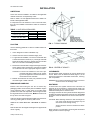
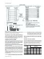
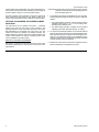
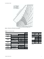
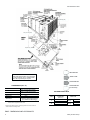
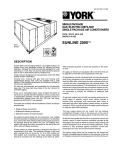
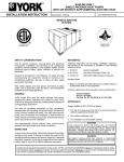
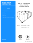
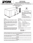
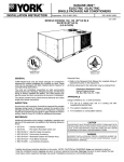
® INSTALLATION INSTRUCTION SUNLINE 2000 SINGLE PACKAGE AIR-TO-AIR HEAT PUMPS 035-18895-000-A-0902 Supersedes: Nothing MODELS B2CH180 (WORLD 50 HZ) GENERAL YORK Model B*CH units are single package heat pumps designed for outdoor installation on a rooftop or a slab. These units can be equipped with factory installed electric heaters for supplemental heating applications. The units are completely assembled on rigid, permanently attached base rails. All piping, refrigerant charge, and electrical wiring is factory installed and tested. The units require only electric power, duct connections and installation of fixed outdoor air intake damper (units without economizer or motorized damper option only) at the point of installation. These units are designed and manufactured under ISO 9002 Quality System Certification • • • • 55.70-N7- General Installation 55.70-N2 -Pre-start & Post-start Check List 44-320-10 - Barometric Relief Damper Accessory Renewal Parts: - Refer to the Renewal Parts Manual for complete listing of replacement parts on this equipment. All forms referenced in this instruction may be ordered from: Standard Register Norman, Oklahoma 73069 Toll Free Telephone: 877-318-9675 Toll Free Fax: 877-379-7920 The supplemental electric heaters have nickel-chrome elements and utilize single point power connection. INSPECTION As soon as a unit is received, it should be inspected for possible damage during transit. If damage is evident, the extent of the damage should be noted on the carrier's freight bill. A separate request for inspection by the carrier's agent should be made in writing. See Local Distributor for additional information. REFERENCE Additional information on the design, installation, operation and service of this equipment is available in the following reference documents: CAUTION THIS PRODUCT M UST BE INSTALLED IN STRICT COMPLIANCE W ITH THE ENCLOSED INSTALLATION INSTRUCTIONS AND ANY APPLICABLE LOCAL, STATE, AND NATIONAL CODES INCLUDING, BUT NOT LIMITED TO, BUILDING, ELECTRICAL, AND MECHANICAL CODES. WARNING INCORRECT INSTALLATION MAY CREATE A CONDITION WHERE THE OPERATION OF THE PRODUCT COULD CAUSE PERSONAL INJURY OR PROPERTY DAMAGE. Installer should pay particular attention to the words: NOTE, CAUTION and WARNING. Notes are intended to clarify or make the installation easier. Cautions are given to prevent equipment damage. Warnings are given to alert installer that personal injury and/or equipment damage may result if installation procedure is not handled correctly. 035-18895-000-A-0902 TABLE OF CONTENTS General................................................................................1 MAINTENANCE Normal Maintenance..................................................... Inspection ............................................................................1 Reference ............................................................................1 15 TABLES Nomenclature ......................................................................2 No. INSTALLATION Limitations ...........................................................................3 Location ...............................................................................3 Rigging and Handling ..........................................................3 Clearances ..........................................................................3 Ductwork .............................................................................3 Fixed Outdoor Air Intake Damper........................................4 Condensate Drain ...............................................................4 Compressors .......................................................................4 Description Page 1 Unit Application Data.................................. 3 2 Electric Heat Application Data.................... 5 3 Physical Data ............................................. 7 4 Supply Air Blower Performance ................. 10 5 Static Resistances...................................... 11 6 Blower Motor and Drive Data ..................... 11 7 Electrical Data (Basic Units)....................... 11 8 Electrical Data (Units w/Elec. Heat) ........... 11 9 Heat Anticipator Setpoints.......................... 13 10 Blower Motor Pulley Adjustment ................ 13 Filters...................................................................................4 FIGURES Service Access ....................................................................4 No. Thermostat ..........................................................................4 Description Page 1 Typical Rigging........................................... 3 2 Center of Gravity ........................................ 3 3 Fixed Outdoor Air Damper ......................... 4 4 Recommended Drain Piping ...................... 4 5 Typical Field Wiring .................................... 5 Cooling System .................................................................12 6 Enthalpy Setpoint Adjustment .................... 7 Preliminary Operation........................................................12 7 Dimensions and Clearances ...................... 8 Cooling Sequence of Operation ........................................12 8 Belt Adjustment .......................................... 13 Heating Sequence of Operation ........................................12 9 Pressure Drop versus Supply Airflow......... 13 Heat Anticipator Setpoint...................................................13 10 Defrost Initiation Times .............................. 14 Checking Supply Airflow....................................................13 11 Ambient Modified Time/Temp. Control ....... 15 Power and Control Wiring ...................................................5 Optional Electric Heaters.....................................................5 Optional Econ./Motorized Damper Rain Hood ....................6 OPERATION Defrost Sequence of Operation .........................................14 Secure Owner's Approval..................................................15 PRODUCT NOMENCLATURE B 1 C H 1 8 0 E 0 3 6 5 0 PRODUCT CATEGORY B = Single Package Heat Pump (Air Cooled) PRODUCT GENERATION VOLTAGE CODE 2 = 2nd Generation 50 = 400/415-3+N-50 PRODUCT IDENTIFIER CH = Heat Pump NOMINAL COOLING CAPACITY 180 = 49.5 kW (169 MBH) 2 FACTORY INSTALLED HEAT A = No Heat E = Electric Heat NOMINAL HEATING CAPACITY 018 = 18 kW 036 = 36 kW 054 = 54 kW 072 = 72 kW Unitary Products Group 035-18895-000-A-0902 INSTALLATION LIMITATIONS These units must be installed in accordance with applicable national and local or municipal safety codes. Refer to Table 1 for Unit Application Data and to Table 2 for Electric Heat Application Data. If components are to be added to a unit to meet local codes, they are to be installed at the dealer's and/or the customer's expense. TABLE 1 - UNIT APPLICATION DATA Voltage Variation (Min. / Max.) Wet Bulb Temperature of Air on Indoor Coil, (Min. / Max.) Dry Bulb Temperature of Air on Outdoor Coil, (Min./ Max.) 400 / 415V °C °F °C °F 360 / 456V 14 / 22 57 / 72 7 / 52 45 / 125 LOCATION FIG. 1 - TYPICAL RIGGING Use the following guidelines to select a suitable location for these units. OUTDOOR COIL END OF UNIT 1. Unit is designed for outdoor installation only. 2. Outdoor coils must have an unlimited supply of air. 3. For ground level installation, use a level concrete slab with a minimum thickness of 102mm (4"). The length and width should be at least 152mm (6") greater than the unit base rails. Do not tie slab to the building foundation. 4. Roof structure must be able to support the weight of the unit and its options and/or accessories. Unit must be installed on a solid level roof curb or appropriate angle iron frame. CAUTION: If a unit is to be installed on a roof curb or special frame other than a YORK roof curb, gasketing must be applied to all surfaces that come in contact with the unit underside. 5. Maintain level tolerance to 13mm (1/2") maximum across the entire length or width of the unit. RIGGING AND HANDLING Exercise care when moving the unit. Do not remove any packaging until the unit is near the place of installation. Rig the unit by attaching chain or cable slings to the lifting holes provided in the base rails. Spreaders, whose length exceeds the largest dimension across the unit, MUST be used across the top of the unit. Refer to Figure 1. Units may also be moved or lifted with a forklift, from the front or rear only, providing that an accessory skid is used. LENGTH OF FORKS MUST BE A MINIMUM OF 2286mm (90"). Refer to Table 3 for unit weights and to Figure 2 for approximate center of gravity. Unitary Products Group 2337 (92") 1524 (60") 1143 (45") 3181 (125-1/4") (180) FIG. 2 - CENTER OF GRAVITY CLEARANCES All units require certain clearances for correct operation and service. Refer to the unit dimensions detail, Figure 7, for the clearances required for combustible construction, servicing, and unit operation. WARNING: Do not permit overhanging structures or shrubs to obstruct outdoor air discharge outlet. DUCTWORK A closed return duct system shall be used. This does not preclude use of economizers or outdoor fresh air intake. The supply and return air duct connections at the unit should be made with flexible joints to minimize noise. The supply and return air duct systems should be designed for the airflow and static requirements of the job. They should NOT be sized to match the dimensions of the duct connections on the unit. CAUTION: When fastening ductwork to side duct flanges on unit, insert screws through duct flanges only. DO NOT insert screws through casing. Outdoor ductwork must be insulated and waterproofed. Refer to Figure 7 for information concerning side and bottom supply and return air duct openings. 3 035-18895-000-A-0902 FIXED OUTDOOR AIR INTAKE DAMPER CONDENSATE DRAIN This damper assembly is shipped inside the return air compartment. It is completely assembled and ready for installation. A damper baffle inside the hood is adjustable to provide variable amounts of outdoor air intake on units that are not provided with an economizer or motorized damper option. Refer to Figure 3. Plumbing must conform to local codes. Use a sealing compound on male pipe threads. Install a condensate drain line from the 25mm (1" NPT) female connection on the unit to spill into an open drain. Gasketing and mounting screws are provided in a parts bag attached to the hood assembly. Apply gasketing to the three flange surfaces on the hood prior to installing the hood. Extend gasketing approximately 6mm (1/4") beyond the top and bottom of the two side flanges to ensure adequate sealing. An alternate drain connection (25mm [1" NPT] female coupling) is provided inboard on the same centerline as the exterior location. NOTE: The condensate drain line MUST be trapped to provide proper drainage. See Figure 4. Adjusting the damper to the desired air flow may be done before mounting the hood into position or (after installation) by removing the front hood panel or the screen on the bottom of the hood. Damper baffle in position 1 will allow approximately 10% recirculated air flow, position 2 approximately 15% and, to allow approximately 25%, remove the damper baffle. On units with bottom return air applications, install the damper assembly over the opening in the side return air access panel. Remove and discard the opening cover and the covering over the hood mounting holes (used for shipping) before installing. Secure with the screws provided. On units with side air applications, install the damper assembly on the return air ductwork as close to the unit as possible. Cut an opening 406mm (16") high by 457mm (18") wide in the ductwork to accommodate the damper. Using the holes in the hood flanges as a template, drill 3.6mm (9/64") dia. (#26 drill) holes into the ductwork and secure with the screws provided. CAUTION: If outdoor air intake will not be required on units with bottom return air applications, the damper assembly should still be mounted on the side return air access panel, per the instructions above, to ensure moisture is not drawn into the unit during operation. The covering over the mounting holes only need be removed. Do not remove the opening cover. FIG. 4 - RECOMMENDED DRAIN PIPING COMPRESSORS Units are shipped with compressor mountings factory-adjusted and ready for operation. CAUTION: Do Not loosen compressor mounting bolts. FILTERS Each unit is supplied with 51mm (2") filters. Filters must always be installed ahead of the indoor coil and must be kept clean or replaced with same size and type. Dirty filters reduce the capacity of the unit and result in frosted coils or safety shutdown. Minimum filter area and required sizes are shown in Table 3. SERVICE ACCESS Access to all serviceable components is provided by the following removable panels: • • • • • • • Compressor compartment Electric Heat compartment Side Supply & Return Air compartments (two panels) Main control box Blower compartment (three panels) Filter compartment Outdoor Air compartment (two panels) Refer to Figure 7 for location of these access panels. CAUTION: Make sure that all screws and panel latches are replaced and properly positioned on the unit to maintain an air-tight seal. THERMOSTAT FIG. 3 - FIXED OUTDOOR AIR DAMPER 4 The room thermostat should be located on an inside wall approximately 1422mm (56") above the floor where it is not subject to drafts, sun exposure or heat from electrical fixtures or appliances. Follow manufacturer's instructions enclosed with thermostat for general installation procedure. Color coded Unitary Products Group 035-18895-000-A-0902 NEUTRAL TERMINAL BLOCK POWER WIRING CONTACTOR NOTE: REFER TO ELECTRICAL DATA TABLES TO SIZE THE WIRE, DISCONNECT SWITCH AND OVERCURRENT PROTECTION. GRD. LUG FIELD-SUPPLIED DISCONNECT THREE PHASE POWER SUPPLY FIG. 5 - TYPICAL FIELD WIRING insulated wires 1.0mm2 (#18 AWG) should be used to connect thermostat to unit. Eight conductors are required. The subbase on the low voltage thermostat includes an “Emergency Heat ” position on the system switch and a pilot light. In the “Emergency Heat” position, the thermostat provides electric resistance heat only. The compressors will not run. The pilot light indicates that the switch is on “EM HT”. Nine conductors are required for this application. POWER AND CONTROL WIRING Field wiring to the unit and electrical grounding of the unit must conform to the applicable national, and local or municipal codes. Voltage tolerances which must be maintained at the compressor terminals during starting and running conditions are indicated on the unit Rating Plate and Table 1. The internal wiring harness furnished in this unit is an integral part of the unit. Field alteration to comply with electrical codes should not be required. A fused disconnect switch should be field provided for the unit. The switch must be separate from all other circuits. Refer to Figure 7 for installation location. If any of the wire supplied with the unit must be replaced, replacement wire must be of the type shown on the wiring diagram. Refer to Table 7 for electrical data. Electrical line must be sized correctly to carry the load. USE COPPER CONDUCTORS ONLY. Each unit must be wired with a separate branch circuit fed directly from the meter panel and properly fused. CAUTION: When connecting electrical power and control wiring to the unit, waterproof type connectors MUST Unitary Products Group BE USED so that water or moisture cannot be drawn into the unit during normal operation. The above waterproofing conditions will also apply when installing a field-supplied disconnect switch. Refer to Figure 5 for typical field wiring and to the appropriate unit wiring diagram for control circuit and power wiring information. OPTIONAL ELECTRIC HEATERS The factory installed heaters are wired for single point power supply. Power supply need only be brought into the single point terminal block and thermostat wiring to the low voltage terminal strip located in the upper portion of the unit control box. TABLE 2 - ELECTRIC HEAT APPLICATION DATA Heater Model E018 E036 E054 E072 Minimum Airflow m3/s (CFM) 180 2.12 (4500) 2.12 (4500) 2.36 (5000) 2.36 (5000) Output by Operation Mode and Heat Stage kW @ 400/415V* Normal Operation Emergency Heat W1 W2 W1 W2 Mechanical 11.3/13.5 11.3/13.5 None Mechanical 11.3/13.5 11.3/13.5 11.3/13.5 Mechanical 11.3/13.5 11.3/13.5 22.6/26.9 Mechanical 22.6/26.9 22.6/26.9 22.6/26.9 *Refer to Table 8 for total heater output kW for the respective heater. 5 035-18895-000-A-0902 These heaters are located within the central compartment of the unit with the heater elements extending into the supply air chamber. Refer to Figure 7 for access panel location. CAUTION: Extreme care must be exercised in turning both the setpoint and minimum position adjusting screws to prevent twisting them off. Fuses are supplied, where required, by the factory. Some KW sizes require fuses and others do not. Refer to Table 2 for minimum air flow limitations and to Table 8 for electrical data. 1. The enthapy set point for the dampers may now be set by selecting the desired setpoint shown in Figure 6. Adjust as follows: OPTIONAL ECONOMIZER / MOTORIZED DAMPER RAIN HOOD • For single enthalpy operation, carefully turn the setpoint The instructions for the optional economizer / motorized damper rain hood can be found in form 44-320-2. The procedures listed in those instructions should be used when field assembling an economizer rain hood onto a unit. The outdoor and return air dampers, the damper actuator, the damper linkage, the outdoor and return air divider baffles, and all the control sensors are factory mounted as part of the “factory installed” economizer option. • ENTHALPY SETPOINT ADJUSTMENT Remove the economizer access panel from the unit to check the following adjustments. Loosen but do not remove the two panel latches. 6 adjusting screw to the “A”, “B”, “C” or “D” setting corresponding to the lettered curve. For dual enthapy operation, carefully turn the setpoint adjusting screw fully clockwise past the “D” setting. 2. To check that the damper blades move smoothly without binding, carefully turn the minimum postion adjusting screw fully clockwise and then energize and de-energize terminals “R” to “G”. With terminals “R” to “G” energized, turn the minimum position screw counterclockwise until the desired minimum position has been attained. 3. Replace the economizer access panel. Reposition the two latches horizontally and retighten the screws. Unitary Products Group 035-18895-000-A-0902 FIG. 6 - ENTHALPY SETPOINT ADJUSTMENT TABLE 3 - PHYSICAL DATA COMPONENT DESCRIPTION SUPPLY AIR BLOWER INDOOR COIL OUTDOOR FANS FAN MOTOR ROWS DEEP FINS PER INCH FACE AREA PROPELLER DIA. FAN MOTOR (Two Per Unit) NOMINAL AIRFLOW OUTDOOR COIL ROWS DEEP FINS PER INCH FACE AREA COMPRESSOR (Qty. Per Unit) AIR FILTERS DIA. x WD. (mm) DIA. x WD. (in.) kW / HP CENTRIFUGAL BLOWER m2 / Ft.2 mm / in. kW / HP m3/s CFM m2 / Ft.2 SCROLL (6.5 TON NOMINAL CAPACITY) QUANTITY PER UNIT (SEE NOTE) TOTAL FACE AREA CHARGE REFRIGERANT 22 457 x 610 x 51 (mm) 18 x 24 x 2 (in.) m2 / Ft.2 SYS. #1 (kg. / lbs.) SYS. #2 (kg. / lbs.) UNIT SIZE 180 381 x 381 15 x 15 3.0 / 4 4 13 1.45 / 15.5 762 / 30 ea. 0.7 / 1 ea. 2.83 ea. 6000 3 15 3.35 / 36.0 2 WEIGHTS (kg. / lbs.) BASIC 180 948 / 2091 UNIT OPTIONS Economizer 73 / 160 Motorized Damper 68 / 150 18 kW 11 / 25 36kW 14 / 30 Electric Heater 54 kW 16 / 35 72 kW 18 / 40 ACCESSORIES Roof Curb 180 79 / 175 Barometric Damper 20 / 45 Wood 180 91 / 200 Skid* *Allows handling of unit using 2286mm (90") long forks. 5 1.40 / 15.0 9.5 / 21.0 9.5 / 21.0 NOTE: Filter racks are adapted to accept 25mm (1") or 51mm (2") filters. Unitary Products Group 7 035-18895-000-A-0902 1235 (48-5/8") (180) 3181 (125-1/4") (180) 616 (24-1/4”) (180 MBH RETURN AIR All dimensions are in millimeters and inches, unless otherwise specified. They are subject to change without notice. Certified dimensions will be provided upon request. SUPPLY AIR OUTDOOR AIR CLEARANCES (mm / in.) Front Back Left Side (Filter Access) Right Side (Outdoor Coil) Below Unit Above Unit* 914 / 36 610 / 24 (Less Economizer) 1245 / 49 (With Economizer) 610 / 24 914 / 36 20 / 0 1829 / 72 With 914 / 36 Maximum Horizontal Overhang (For Outdoor Air Discharge) NOTE: Unit and ductwork are approved for zero clearance to combustible materials when equipped with electric heat. *Units must be installed oudoors. Overhanging structures or shrubs should not OUTDOOR AIR (Economizer) UTILITIES ENTRY DATA HOLE A B OPENING DIAMETER (mm / in.) 28.6 / 1-1/8 KO 19.1 / 3/4 NPS (Fem.) 92.1 / 3-5/8 KO 76.2 / 3 NPS (Fem.) USED FOR Control Wiring Power Wiring Front Bottom Front Bottom obstruct outdoor air discharge outlet. FIG. 7 - DIMENSIONS AND CLEARANCES 8 Unitary Products Group 035-18895-000-A-0902 DUCT COVERS - Units are shipped with all air duct openings covered. For sideflow duct applications; 1.Remove and discard the side supply and return air duct covers. 2.Connect ductwork to duct flanges on the rear of the unit. For downflow duct applications; 1. Remove the side supply and return air duct covers to gain access to the bottom supply and return air duct covers. 2. Remove and discard the bottom duct covers. 3. Replace the side duct covers. 727 (28-5/8") (180) DETAIL “X” ACCESSORY SIDE SUPPLY AND RETURN AIR DUCT OPENINGS 397 155 8“ 610 (24") (180) DETAIL “Y” UNIT WITH ECONOMIZER AND FIXED OUTDOOR AIR HOODS FIG. 7 (Cont'd.) - DIMENSIONS AND CLEARANCES Unitary Products Group 9 035-18895-000-A-0902 TABLE 4 - SUPPLY AIR BLOWER PERFORMANCE DOWNFLOW DUCT APPLICATIONS (m3 /s) - B*CH180 UNIT MOTOR BLOWER PULLEY SPEED, (TURNS RPM OPEN)* 845 6.0 885 5.0 925 4.0 960 3.0 1000 2.0 1040 1.0 ESP (Pa) 273 322 372 422 446 496 1.77 m3/s Output Input (kW) (kW) 1.56 1.8 1.64 1.9 1.71 2.1 1.79 2.2 1.86 2.3 1.94 2.4 ESP (Pa) 223 273 322 347 397 446 2.07 m3/s Output (kW) 1.79 1.94 2.01 2.16 2.24 2.38 Input (kW) 2.2 2.3 2.5 2.6 2.7 2.9 AIRFLOW 2.36 m3/s ESP Output Input (Pa) (kW) (kW) 198 2.09 2.5 223 2.24 2.7 248 2.38 2.9 298 2.46 3.0 347 2.61 3.2 372 2.76 3.3 ESP (Pa) 174 198 223 248 - 2.66 m3/s Output (kW) 2.38 2.53 2.68 2.83 - Input (kW) 2.9 3.1 3.3 3.4 - ESP (Pa) 149 174 - 2.95 m3/s Output (kW) 2.68 2.83 - Input (kW) 3.2 3.4 - DOWNFLOW DUCT CONNECTIONS (CFM) - B*CH180 UNIT BLOWER SPEED, (RPM) 845 885 925 960 1000 1040 MOTOR PULLEY (TURNS OPEN)* 6.0 5.0 4.0 3.0 2.0 1.0 3750 CFM ESP Output Input (iwg) (bhp) (kW) 1.1 2.1 1.8 1.3 2.2 1.9 1.5 2.3 2.1 1.7 2.4 2.2 1.8 2.5 2.3 2.0 2.6 2.4 4380 CFM ESP Output Input (iwg) (bhp) (kW) 0.9 2.4 2.2 1.1 2.6 2.3 1.3 2.7 2.5 1.4 2.9 2.6 1.6 3.0 2.7 1.8 3.2 2.9 AIRFLOW 5000 CFM ESP Output Input (iwg) (bhp) (kW) 0.8 2.8 2.5 0.9 3.0 2.7 1.0 3.2 2.9 1.2 3.3 3.0 1.4 3.5 3.2 1.5 3.7 3.3 5630 CFM ESP Output Input (iwg) (bhp) (kW) 0.7 3.2 2.9 0.8 3.4 3.1 0.9 3.6 3.3 1.0 3.8 3.4 - 6250 CFM ESP Output Input (iwg) (bhp) (kW) 0.6 3.6 3.2 0.7 3.8 3.4 - NOTES: 1. Blower performance includes fixed outdoor air, standard unit filters, a dry indoor coil and no electric heat. 2. Refer to Table 5 for additional static resistances. ESP = External Static Pressure available for the supply and return air duct system. All internal unit resistances have been deducted from the total static pressure of the blower. * Do NOT close the pulley below 1 turn open. 10 Unitary Products Group 035-18895-000-A-0902 TABLE 5 - STATIC RESISTANCES1 EXTERNAL STATIC PRESSURE DROP - RESISTANCE, iwg/Pa m3/s (CFM) 180 UNIT 1.77 (3750) 2.12 (4500) 2.48 (5250) 2.83 (6000) 0.1 / 25 0.1 / 25 0.1 / 25 0.1 / 25 0.1 / 25 0.1 / 25 0.1 / 25 0.1 / 25 0.1 / 25 0.1 / 25 0.2 / 50 0.2 / 50 0.1 / 25 0.2 / 50 0.2 / 50 0.3 / 75 0.1 / 25 0.2 / 50 0.3 / 75 0.4 / 99 0.1 / 25 0.1 / 25 0.1 / 25 0.1 / 25 0.2 / 50 0.2 / 50 0.3 / 75 0.3 / 75 DESCRIPTION WET COIL ELECTRIC HEAT OPTIONS 18 kW 36 kW 54 kW 72 kW ECONOMIZER OPTION SIDEFLOW DUCT CONNECTIONS2 1 Deduct these resistance values from the available external static pressures shown in the respective Blower Performance Table. (See Note 2 for exception). 2 Since the resistance to air flow will be less for sideflow duct connections than for downflow duct connections, add these pressures to the ESP values listed on the respective blower performance table. TABLE 6 - BLOWER MOTOR AND DRIVE DATA UNIT SIZE (MBH) 180 ADJUSTABLE FIXED BELT (NOTCHED) MOTOR1 MOTOR PULLEY2 BLOWER PULLEY BLOWER RANGE DESIG- PITCH FRAME EFF. PITCH DIA. BORE DESIG- PITCH DIA. BORE DESIG(RPM) kW/HP NA- LENGTH QTY SIZE (%) (mm / in.) (mm / in.) NATION (mm / in.) (mm / in.) NATION TION (mm / in.) 109 - 135 / 1773 / 845 - 1040 3.0/4.0 184T 83 29 / 1-1/8 1VP56 188 / 7.4 25 / 1 BK80 BX68 1 4.3 - 5.3 69.8 1 All 2 motors are 1450 RPM, have solid bases and a 1.10 service factor. Do NOT close this pulley below 1 turn open. TABLE 7 - ELECTRICAL DATA (BASIC UNITS) UNIT MODEL 180 NOTES: POWER SUPPLY (VOLTS) 380-415/3/50 COMPRESSOR (#1 and #2) RLA EACH 12.8 LRA EACH 95 OUTDOOR FAN MOTOR, (#1 & #2) FLA EACH 2.1 SUPPLY AIR BLOWER MOTOR MAXIMUM FUSE SIZE1 FLA MINIMUM CIRCUIT AMPACITY, (AMPS) 8.6 41.6 50 1. Slow blow type fuse. 2. Based on 105°C copper conductors. TABLE 8- ELECTRICAL DATA (UNITS WITH ELECTRIC HEAT) UNIT MODEL POWER SUPPLY (VOLTS) 380-3-50 180 415-3-50 NOTES: HEATER OPTION MODEL kW STAGES AMPS E018 E036 E054 E072 E018 E036 E054 E072 11.3 22.6 33.8 45.1 13.5 26.9 40.4 53.8 1 2 2 2 1 2 2 2 17.1 34.3 51.4 68.6 18.7 37.4 56.2 74.9 MINIMUM CIRCUIT AMPACITY (AMPS) 63.1 63.1 75.0 96.5 65.0 65.0 80.9 104.3 MAXIMUM FUSE SIZE1 70 70 80 100 70 70 90 110 1. Slow blow type fuse. 2. Based on 105°C copper conductors. Unitary Products Group 11 035-18895-000-A-0902 OPERATION COOLING SYSTEM The cooling section is a complete factory package utilizing an air-cooled condenser. The system is factory-charged with Refrigerant-22. The compressors are hermetically sealed, internally sprung and base-mounted with rubber-insulated hold-down bolts. The compressors also have inherent (internal) protection. If there is an abnormal temperature rise in a compressor, the protector opens to shut down the compressor. PRELIMINARY OPERATION After installation has been completed, energize the crankcase heaters for at least four hours before operating unit. After this initial warm-up, the compressors should be given three false starts (energized just long enough to make a few revolutions) with 5-7 minutes delay between each start before being put into full time service. NOTE: Prior to each cooling season, the crankcase heaters must be energized at least 8 hours before system is put into operation. COOLING SEQUENCE OF OPERATION NO OUTDOOR AIR OPTIONS - When the room thermostat calls for “first-stage” cooling, the low voltage control circuit from “R” to “G” and “Y1” is completed to energize compressor #1, outdoor fan motor #1, outdoor fan motor #2 (if the ambient temperature is above 16°C (60°F)), and the supply air blower motor (if the fan switch on the room thermostat is set in the “AUTO” position). When the thermostat calls for “second-stage” cooling, the low voltage control circuit from “R” to “Y2”is completed to energize compressor #2. After the thermostat is satisfied and opens, all components stop simultaneously. The blower motor continues to operate if the fan switch on the room thermostat is set in the “ON” position. The reversing valve is energized thru the “Y1” circuit when the subbase is in the cooling mode. The suction line freezestat cuts the compressors out when the suction line temperature drops below -3°C (26°F). This is an automatic reset device. ECONOMIZER WITH SINGLE ENTHALPY SENSOR - When the room thermostat calls for “first-stage” cooling, the low voltage control circuit from “R” to “G” and “Y1” is completed. The “R” to “G” circuit energizes the blower motor (if the fan switch on the room thermostat is set in the “AUTO” position) and drives the economizer dampers from fully closed to their minimum position. If the enthalpy of the outdoor air is below the setpoint of the enthalpy controller (previously determined), “Y1” energizes the economizer. The dampers modulate to maintain a constant supply air temperature as monitored by the 12 discharge air sensor. If the outdoor air enthalpy is above the setpoint, “Y1” energizes compressor #1, outdoor fan motor #1, and outdoor fan motor #2 (if the ambient temperature is above 16°C (60°F)). When the thermostat calls for “second-stage” cooling, the low voltage control circuit from “R” to “Y2” is completed. If the enthalpy of the outdoor air is below the setpoint of the enthalpy controller (i.e., first stage has energized the economizer), “Y2” energizes compressor #1. If the outdoor air is above the setpoint, “Y2” energizes compressor #2. After the thermostat is satisfied and opens, all components stop simultaneously. The blower motor continues to operate if the fan switch on the room thermostat is set in the “ON” position. ECONOMIZER WITH DUAL ENTHALPY SENSORS - The operation with the dual enthalpy sensors is identical to the single sensor except that a second enthalpy sensor is mounted in the return air. This return air sensor allows the economizer to choose between outdoor air and return air, whichever has the lowest enthalpy value, to provide maximum operating efficiency. ECONOMIZER (SINGLE OR DUAL) WITH POWER EXHAUST - This system operates as specified above with one addition. The power exhaust motor is energized whenever the economizer is chosen by the enthalpy sensor for first stage cooling, “Y1”. As always, the “R” to “G” connection provides minimum position but does not provide power exhaust operation. MOTORIZED OUTDOOR AIR DAMPERS - This system operation is the same as the units with no outdoor air options with one exception. When the “R” to “G” circuit is complete, the motorized damper drives open to a position set by the thumbwheel on the damper motor. When the “R” to “G” circuit is opened, the damper spring returns fully closed. HEATING SEQUENCE OF OPERATION The following sequence of operation is based on using a standard heat pump two-stage heating/two-stage cooling thermostat/subbase. Economizer (if supplied) operation is not allowed in the heating mode; however, the minimum position does operate. FIRST STAGE HEAT When the thermostat calls for “heating”, the low voltage control circuit from “R” to “G”and “W1” (wiring schematic) is completed to energize the compressors, outdoor fan motors and blower motor (if subbase is set on auto) simultaneously. If the subbase has the indoor fan set on “on” the motor will run all of the time. SECOND STAGE HEAT If the compressors alone can not satisfy the heating requirements, second stage heat energizes all the electric heat (if supplied) thru the “W2” circuit. Unitary Products Group 035-18895-000-A-0902 HEAT ANTICIPATOR SETPOINT It is important that the anticipator setpoint be correct. Too high a setting results in longer heat cycles and a greater temperature swing in the conditioned space. Reducing the value below the correct setpoint causes shorter “ON” cycles and may result in the lowering of the temperature within the conditioned space. Refer to Table 9 for the required heat anticipator setting. TABLE 10 - SUPPLY AIR BLOWER MOTOR PULLEY ADJUSTMENT TABLE 9 - HEAT ANTICIPATOR SETTING HEATER kW 18 36 54 72 SETTING, AMPS TH1 0.29 0.29 0.29 0.29 TH2 0.29 0.29 0.29 CHECKING SUPPLY AIRFLOW The RPM of the supply air blower will depend on the required airflow, the unit accessories and the static resistances of both the supply and the return air duct systems. With this information, the RPM for the supply air blower and the motor pulley adjustment (turns open) can be determined from the blower performance data in Table 4. Knowing the required blower RPM and the blower motor HP, the setting (turns open) for the supply air motor pulley can be determined from Table 10. BELT DRIVE BLOWER All units have belt drive single-speed blower motors. The variable pitch pulley on the blower motor can be adjusted to obtain the desired supply air flow. Note the following: 1. The supply airflow must be within the limitations shown in Table 1. 2. Pulleys can be adjusted in half turn increments. BLOWER DRIVE RANGE (RPM) 180 UNIT 845 885 925 960 1000 1040 TURNS OPEN* 6 5 4 3 2 1 *Pulleys can be adjusted in half-turn increments. Do NOT close pulley below 1 turn open. distribution throughout the conditioned space. The job specifications may require that this balancing be done by someone other than the equipment installer. To check the supply airflow after the initial balancing has been completed: 1. Remove the two dot plugs from the blower motor and the filter access panels shown in Figure 7. 2. Insert at least 200mm (8") of tubing (approximately 6mm (1/4") diameter) into each of these holes for sufficient penetration into the air flow on both sides of the indoor coil. NOTE: The tubes must be inserted and held in a position perpendicular to the air flow so that velocity pressure will not affect the static pressure readings. 3. Using an inclined manometer, determine the pressure drop across a dry indoor coil. Since the moisture on an indoor coil may vary greatly, measuring the pressure drop across a wet coil under field conditions would be inaccurate. To ensure a dry coil, the compressors should be de-energized while the test is being run. 4. Knowing the pressure drop across a dry coil, the actual air flow through the unit and clean filters, can be determined from the curve in Figure 9. 3. The tension on the belt should be adjusted as shown in Figure 8. WARNING: Failure to properly adjust the total system air quantity can result in extensive blower damage. Start the supply air blower motor. Adjust the resistances in both the supply and the return air duct systems to balance the air After readings have been obtained, remove the tubes and reinstall the two dot plugs that were removed in Step 1. NOTE: DE-ENERGIZE THE COMPRESSORS BEFORE TAKING ANY TEST MEASUREMENTS TO ENSURE A DRY INDOOR COIL. 3 2.4 m /s SUPPLY AIR 2.8 3.3 3.8 PRESSURE DROP (iwg) 0.65 4.2 4.7 1.61 180 MBH 0.55 1.36 0.45 1.12 0.35 81 PRESSURE DROP (Pa) 1.9 62 0.25 4 5 6 7 8 9 10 NOMINAL CFM (THOUSANDS) SUPPLY AIR FIG. 8 - BELT ADJUSTMENT Unitary Products Group FIG. 9 - PRESSURE DROP ACROSS A DRY INDOOR COIL VS SUPPLY AIRFLOW 13 035-18895-000-A-0902 DEFROST SEQUENCE OF OPERATION LOCKOUT CONTROL These heat pumps have a unique “ambient modified” timetemperature defrost control that automatically adjusts to changes in the outdoor temperature. The defrost control shortens the defrost initiation time periods above 2°C (35°F) and extends the defrost initiation time periods below 2°C (35°F. The control is factory set to defrost at 110 minutes (T3), but it can be field adjusted to defrost at 80 minutes (T2) or 50 minutes (T1) in areas with high humidity. Any one of four conditions put the system into a lock-out condition during the heating or cooling mode: The curve in Figure 10 shows how defrost initiation times are automatically compensated for changes in outdoor temperature. 3. The suction line freezestat equals -3°C (26°F) (3°C reset [38°F]), or EXAMPLE: If the timer is factory set on pin T3 (110 minutes at 2°C (35°F) outdoor) and the outdoor temperature climbs to 7°C (45°F), the time initiation cycle decreases to 100 minutes. If the outdoor temperature drops to -12°C (10°F) where ice is less likely to form, the 110 minute interval increses to 150 minutes. 1. The discharge line temperature reaches 124°C (255°F) (102°C reset [215°F]) or, 2. The discharge pressure reaches 2,786 kPa (398 psig) (2,170 kPa reset [310 psig]) or, 4. The low-pressure cut-out equals 49 kPa (7 psig) (154 kPa [22 psig]). A lock-out energizes the emergency heat light on the thermostat and the red LED light on the unit relay board. Turning the thermostat switch to “off”, then back to “on” will reset the system. NOTICE TO OWNER: Two requirements must be met before a defrost cycle can be initiated. If a lockout occurs, check for the following problems before calling a serviceman: 1. The defrost time cycle must be complete. 1. Dirty filters. 2. The liquid line temperature must be less than -2°C (28°F). 2. Snow accumulation. Defrost terminates when the liquid line sensor reaches 13°C (55°F) or after 10 minutes. If one or both circuits defrosts, electric heat is energized. 3. Leaf or debris blockage. The defrost time cycle restarts 10 minutes after the start of the defrost cycle even though the liquid sensor terminated defrost after three minutes. During troubleshooting, the defrost time can be reduced to 20 seconds by shorting out the SW1 test pegs on the module. The pegs are 13mm (1 2 in.) long, 5mm (3 16 in.) apart and are mounted on a white base. See Figure 11. -23 (-10) -17 (0) -12 (10) -7 (20) After eliminating the problem, attempt to restart the system as follows: • turn the system switch on the thermostat to its “OFF” position for 10 seconds. • turn it back to its original position. If the unit doesn't start, call a service man. NOTE: Models with an anti-cycle accessory have a five minute delay before restarting. -1 (30) 5 (40) 10 (50) 16 (60) °C (°F) FIG. 10 - DEFROST INITIATION TIMES 14 Unitary Products Group 035-18895-000-A-0902 T2 - 80 MINUTE SETTING T3 - 110 MINUTE SETTING (Factory Set Point) T1 - 50 MINUTE SETTING SHORTING PEGS TO OVERRIDE TIMER FOR SERVICE MOVABLE JUMPER WIRE TO CHANGE DEFROST TIMER FIG. 11 - AMBIENT MODIFIED TIME/TEMPERATURE CONTROL SECURE OWNER'S APPROVAL: When the system is functioning properly, secure the owner's approval. Show him the location of all disconnect switches and the thermostat. Teach him how to start and stop the unit and how to adjust temperature settings within the limitations of the system. MAINTENANCE NORMAL MAINTENANCE CAUTION: Prior to any of the following maintenance procedures, shut off all power to the unit to prevent personal injury. FILTERS - Inspect once a month. Replace disposable or clean permanent type as necessary. DO NOT replace permanent type with disposable. The dimensional size of the replacement filter must be the same as the replaced filter. MOTORS Outdoor fan motors are permanently lubricated and require no maintenance. Indoor Blower Motor and Drive - The indoor blower motor features ball-bearings that do not require periodic lubrication. Periodic lubrication of the motor and bearings can extend the life of components but is optional. CAUTION: Damage can occur if the bearings are overlubricated. Use grease sparingly. On an annual basis, check the motor for accumulations of dust, etc. that may block the cooling slots in the motor shell. Check for loose, damaged or misaligned drive components. Check that all mounting bolts are tight. Replace defective parts as required. If desired, every three years remove both pipe plugs at each end shell and clean out any hardened grease or foreign matter. Replace one plug on each end with a clean grease fitting. Using a low pressure grease gun, pump grease (Chevron SR1-2 or equivalent) into the bearing cavity until new grease shows at the open port. Do not over-lubricate. Run the motor for ten minutes until excess grease is purged from the cavity. Replace the plugs. OUTDOOR COIL - Dirt should not be allowed to accumulate on the outdoor coil surface or other parts in the air circuit. Cleaning should be as often as necessary to keep coil clean. Use a brush, vacuum cleaner attachment, or other suitable means. If water is used to clean coil, be sure power to the unit is shut off prior to cleaning. WARNING: NOTE: Exercise care when cleaning the coil so that the coil fins are not damaged. Perform all maintenance operations on the blower motor with power disconnected from the unit. Do not attempt to lubricate bearings with the unit in operation. Do not permit the outdoor air discharge to be obstructed by overhanging structures or shrubs. Unitary Products Group 15 5005 York Drive, Norman Oklahoma 73069 Subject to change without notice. Printed in U.S.A Copyright by York International Corporation 2002. All Rights Reserved. 035-18895-000-A-0902