1
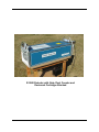
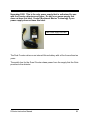
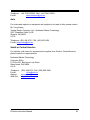
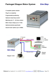
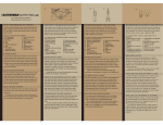
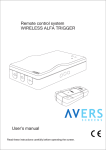
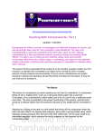
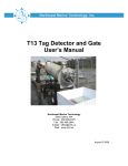
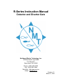
R-Series Instruction Manual Detector and Diverter Gate Northwest Marine Technology, Inc. 976 Ben Nevis Loop Road P.O. Box 427 Shaw Island, WA 98286 Phone: (360) 468–3375 Fax: (360) 468–3844 Web Site: http:/www.nmt.us E-Mail: [email protected] Revision 7.1 March 21, 2003 R 9500 Detector with Gate, Dual Counter and Desiccant Cartridge Attached Table of Contents Table of Contents..........................................................................4 Introduction ...................................................................................6 Part 1: Organization and Use of this Manual. ...............................6 Part 2: Equipment Description ......................................................7 Detector Front Panel ....................................................................................................7 Detector Rear Panel...................................................................................................10 Diverter Gate..............................................................................................................13 Gate Electronics Box..................................................................................................14 Dual Counter ..............................................................................................................15 Quad Counter.............................................................................................................17 Part 3: Equipment Setup .............................................................18 Detector Mounting and Setup.....................................................................................18 Gate Attachment ........................................................................................................18 Dual Counter Attachment ...........................................................................................19 Quad Counter Mechanical Installation........................................................................19 Quad Counter cable connections. ..............................................................................20 Desiccant Cartridge....................................................................................................23 Powering the Equipment ............................................................................................27 Aluminum Leg Assembly............................................................................................29 Part 4: Detailed Operating Procedures .......................................30 Turning on Power .......................................................................................................30 Adjusting Detector Sensitivity.....................................................................................30 Detector Adjustments for use with a Diverter Gate ....................................................31 Counter Operation......................................................................................................32 Part 5: Care and Maintenance ....................................................34 Part 6: Troubleshooting...............................................................36 Sensitivity Adjustment ................................................................................................36 Optimizing Conditions ................................................................................................37 Testing Sensitivity ......................................................................................................37 Alarms and Signals ....................................................................................................38 Power Loss to Gate.................................................................................................38 Gate Latch Hook Position Alarm .............................................................................38 Odd situations .........................................................................................................38 Adjustments ...............................................................................................................38 Gate Latch Bar Stop................................................................................................38 Part 7: Glossary ..........................................................................39 Part 8: Appendix..........................................................................40 Daily Operation of the Detector with a Gate and Counter ..........................................40 Daily Operation of the Detector without a Gate and Counter .....................................43 Detector Specifications...............................................................................................45 R-Series Instruction Manual 4 Dimensions: ............................................................................................................45 Power Consumption ................................................................................................45 Wiring of Power Connector .....................................................................................45 Wiring of Electronics Connector ..............................................................................45 Cleaning and Disinfecting of Equipment.....................................................................47 Optional accessories from NMT and others ...............................................................47 Conveyor Belt Usage .................................................................................................47 Use of R-Series Detector in a Flume..........................................................................48 Other Tag Detection Methods and Equipment ...........................................................48 Shipping Detectors for Repair or Relocation ..............................................................48 Equipment Lists and Weights.....................................................................................49 R-Series Detector....................................................................................................49 Gate with Dual Counter ...........................................................................................49 Quad Counter..........................................................................................................50 Contacting Northwest Marine Technology..................................................................51 R-Series Instruction Manual 5 Introduction There are two models of R-Series Rectangular Tunnel Detectors, the R8000 and the R9500; they are designed to detect the presence of Coded Wire Tags (CWTs) in fish fed through the central tunnel, such as salmon, herring and eels. The R-9500 may also be operated with a conveyor belt running through it for detecting tags in a large volume of small fish. Fish are passed through the tunnel at a rate of 5 to 23 feet/second (1.5 to 7 meters/second). If a fish contains a tag, the Detector responds with an audio alarm, indicator lights, and an electronic signal to activate an optional Diverter Gate. For stand-alone operation (operation without a Gate), an operator manually sorts the exiting fish according to the presence or absence of the alarm signal. The optional Diverter Gate automatically diverts tagged fish to one side and untagged fish to the other as they exit the tunnel, and the Counters tally the fish exiting from each side. Fish are typically slid through the R-Series Detector by hand with the Detector inclined at 10 to 25 degrees while the tunnel is kept wet with a stream of water. Part 1: Organization and Use of this Manual. This manual describes the setup and operation of all R8000 and R9500 Detectors, Diverter Gates, and Counters. Since most of the R-Series Detectors have a Diverter Gate with Counter attached, this manual integrates explanation of the use of the Gate with that of the Detector. For operation without a Gate, all references to the Gate, and the Gate controls on the Detector, may simply be ignored. This manual is separated into several parts. Part 2 Part 3 Part 4 Part 5 Part 6 Part 7 Part 8 Detailed Equipment Description. Assembly, setup, and powering the equipment. Detailed Operating Procedures Care and Maintenance, including disinfection. Troubleshooting, describes alarms, things to avoid and things that must be done to assure consistency and reliability. This section also describes problems and specific solutions where possible. A glossary of terms. An Appendix, which includes a Daily Operations Checklist, detector specifications, shipping instructions and other information. R-Series Instruction Manual 6 Part 2: Equipment Description Detector Front Panel The front panel of the R-Series detector contains the entrance to the tunnel and the control panel as pictured below. The R8000 and R9500 differ only in size. See appendix for size specifications of each machine. Upper LED Display Power Switch Lower LED Display Gate Signal Duration Gate Signal Delay Serial Number Detector Sensitivity Tunnel Power Indicator Tag Threshold Error Low Dead Batteries The Power Switch has two positions, On and Off. If a Diverter Gate is R-Series Instruction Manual 7 attached, power is supplied from the Gate through the Electronics Connector on the rear panel. If used without a Gate, power may be supplied with either two C-cell alkaline batteries in the Battery Holder on the rear panel or, on newer units, from any 6 to 40 volt dc supply or NMT Power Supply connected to the Power Connector on the rear panel. Please see Turning on Power, in Part 4 regarding units with gates. To the right of the power switch are two LED (light emitting diode) displays. The lower display is formed by a horizontal row of 18 red LEDs. The first LED is a power-on indicator; as long as there is power this first LED will be on. The next 14 LEDs are a tag signal display, depicting the size of the magnetic disturbance being detected in the tunnel. The light moves to the right as the signal increases. When it reaches the center of the display, marked Tag Threshol”, the detector recognizes the presence of a tag. At and above "Tag Threshold," a solid bar of LEDs appears to the right. The number of lit LEDs to the right of “Tag Threshold” indicates signal strength. The last three of the 18 LEDs indicate: 1) an Error in conveyor belt timing, 2) Low Batteries, low voltage, and 3) Dead Batteries. The upper round LED display consists of one red LED that illuminates when a detected tag (or excess noise) causes the signal strength to pass the Tag Threshold. The Low Batteries light functions similarly in units with either a Battery Holder or with a Power Connector. In the first case, it indicates that the two C-cell batteries are low (1.1 volts or less each) and should be replaced. It will also indicate when either a 6 volt or 12 volt lead acid battery connected directly to the detector (not the gate) is in need of recharging. The Detector will still function for a short while (up to 10 hours) after this light turns on. The Dead Batteries light indicates that the batteries are so low that the Detector will probably not function correctly. When the Detector, without a gate, is first turned on, the LED bar graph to the right of “Tag Threshold” displays the battery condition. A single light indicates a nearly exhausted alkaline battery giving no more than 0.9 volts per cell. The bar grows to the right with increasing battery condition up to the 1.5 volts per cell of a fresh alkaline battery. Two alkaline C- cells are good for about 60 hours of normal operation. The detector may operate from other types of C- cell batteries, but they are not recommended and may not properly trigger the low battery indicator lights. The LED bar graph to the right of “Tag Threshold” also indicates the charge R-Series Instruction Manual 8 condition of batteries, with one LED indicating very low charge and full scale indicating a fully charged battery. These LEDs stay lit from 10 to 20 seconds depending on the version of the detector. If powering through the Power Connector using the NMT Power Supply, all of the LEDs to the right of “Tag Threshold” will be on for 20 seconds. After the initial battery condition display, the LEDs to the right of “Tag threshold” go out and the microprocessor initializes itself. The detector is now ready to detect noise or a CWT. If the Detector Sensitivity knob is set at the lowest setting (completely counter clockwise) the two most left LEDs will be on. If the sensitivity is adjusted clockwise then the second LED will go off and the third or fourth LED will light. The LED bar graph shows the strength of the detected signal plus noise. A lit LED confined to the left side of “Tag Threshold” indicates a signal smaller than normally produced by a tag. When “Tag Threshold” is reached, the bar of lit LEDs extends beyond the light labeled "Tag Threshold". The detector signals the presence of a tag with both an audible beep and by turning on the large round bright red LEDs near the center of the front and rear panels. There are three adjustments knobs: Detector Sensitivity, Gate Signal Delay, and Gate Signal Duration. The recommended starting positions of these are: 1) Detector Sensitivity turned to approximately 11:00 o'clock, 2) Gate Signal Delay turned all the way down (full counter-clockwise), and 3) Gate Signal Duration turned all the way up (full clockwise). These controls should be further adjusted as described in Part 4. R-Series Instruction Manual 9 Detector Rear Panel The rear panel of the R-Series Detector has the tunnel exit, one or two air vent(s), an audio signal Alarm or (AudioLarm), a Battery compartment; on newer units the Battery compartment has been replaced with a Power Connector, an Electronics Connector, and a large round red Tag Threshold indicator LED, as shown in the figure below. All detectors must have desiccants. Vent with Desiccant Batteries AudioLarm Electronics Connector Tag Threshold Tunnel Older Model Rear Panel of the R-Series Detector As of mid March 2002 all new detectors are being built with a large desiccant cartridge installed above the rear panel. All detectors that were built with two vent holes and no desiccant are being altered to carry desiccant cartridges. If you have a detector that does not have a desiccant, please contact Northwest Marine Technology for more information. R-Series Instruction Manual 10 “DRIERITE” cartridge installed Upper vent One end of hose attached to vent, other to cartridge One end hose attached to cartridge, other end open Plugged lower vent R-Series Detector Rear Panel as of March 2002 The Vent is required to accommodate pressure changes due to changes in weather or altitude (especially during air transport). The upper vent is connected with a few inches of flexible tubing to a desiccant dryer cartridge and the other end of this cartridge is connected to several inches of flexible tubing that is open at the other end. This second piece of tubing reduces the rate of absorption of moisture from damp air and splashed water. To avoid damage to the electronic detection circuitry, the desiccant dryer cartridge or desiccant in the cartridge must be replaced routinely. The life of the desiccant may vary greatly depending on the type of desiccant being used and the size of the cartridge. The fresh desiccant supplied by Northwest Marine Technology is blue (See the end of this section for information about desiccants). On detectors with two vents, the lower vent is plugged. The audio signal Alarm ("AudioLarm") has a fixed volume, but it can easily be made less loud by covering its opening with a piece of tape or placing a foam ear plug in the hole. The audio alarm sounds whenever the Tag Threshold LED lights indicating the presence of a CWT or excess noise. R-Series Instruction Manual 11 The Battery compartment holds two C-cell batteries; only Alkaline batteries should be used, since other types (regular, "heavy duty," rechargeable, or others) will not last as long and will not be correctly monitored by the low battery indicator. The batteries may be left out if a Diverter Gate is used, although the loss-of-power alarm will not function. On later units or retrofitted units the Battery compartment is replaced with a Power Connector. The Power Connector accepts any input voltage from 6 to 40 volts DC, and requires use of an NMT Power Cableconnected to a battery, or an adapter (NMT Power Supply) for operation from utility AC power. Unless otherwise requested, the unit ships with a 12 volt rechargeable sealed lead acid battery, battery box, a battery charger with cables, and an NMT Power supply. On a few detectors the artwork on the rear panel says 6 – 48 VDC. This is not correct. If you would like a new label to cover the incorrect voltage range, please contact NMT. Detach the battery cable from the Power Connector when the detector is not in use to avoid running down the battery. The Electronics Connector connects via a cable to a Diverter Gate: it sends an activation signal to the Gate when a CWT is detected, and can accept electrical power from the NMT Diverter Gate. The Tag Threshold LED on the rear panel is a duplicate of the Tag Threshold LED on the front panel. It turns on when the signal strength is greater than the "Tag Threshold" level as indicated on the LED bar graph of the front control panel. R-Series Instruction Manual 12 Diverter Gate The R-Series Diverter Gate attaches to the rear of the R-Series Detector and works in conjunction with it. Its main components are one upper and one lower "beak" for mechanical support, two latching gate doors, an Electronics Box, and a Counter with sensors. The gate doors are arranged so that fish are diverted to one side or the other depending on which door is unlatched. One gate door is normally latched when there is not a CWT signal and the other is normally unlatched; the latched side is selected by the user using a toggle switch. Untagged fish sliding out of the R-Series Detector will push open the unlatched door and be diverted to that side by the latched door. If the Detector identifies a fish moving through the R-Series Detector as containing a Coded Wire Tag (CWT), then the Detector sends a signal to the Diverter Gate through the Detector's electronics connector on the rear panel. This signal toggles the Diverter Gate latch so that the fish is diverted to the other side. After an adjustable period of time of approximately 1 second, the Diverter Gate returns to its previous state, ready for another fish. The R-Series Diverter Gate can be powered by either a 12-volt sealed-lead-acid battery or by an NMT power supply that plugs into a standard 120 VAC outlet. Electronics Box Upper Beak Counter Cable with Sensors in brackets R 9500 Diverter Gate with fish pushing open the unlatched door and being diverted to the left by the latched door. Latched Door R-Series Instruction Manual 13 Gate Electronics Box The front side of the Gate Electronics Box has seven items: a Power Input Connector, a cable for connecting to the R Detector, a vertically toggled Power Switch a horizontally toggled Direction Switch, an audio Error Alarm, an LED indicating Power On, and an LED indicating a Low Battery. End View of Gate Electronics Box The Power Input Connector on the R-Series Gate connects to either NMT's RSeries Power Supply, which in turn is plugged into a standard 120VAC outlet, or to a 12 volt DC power source such as the supplied 12 volt sealed lead acid battery. The end of the Cable to R Detector connects to the Electronics Connector on the rear panel of the detector. It receives the activation signal from the Detector and also supplies the Detector with 5-volt power. The Power Switch toggles up for on and down for off. If there are C-cells in the Detector and the Gate power is turned off before the Detector is turned off, the Detector Loss of Power Alarm will sound. R-Series Instruction Manual 14 The Direction Switch is toggled to either the left or right. With the gate attached to the detector and the gate power on, set the direction switch so the unlatched door is on the side to which untagged fish are to be diverted. The Error Alarm will sound if the gate latch is in the wrong position. During normal operation the latch will always be in the correct position, but if it is bumped or pushed it can be moved to the wrong position and then the alarm will immediately and continuously sound. The latch can then be manually toggled back to the correct position, or the direction switch can be toggled a couple times to return the latch to the correct position. Either method will correct the error and stop the alarm. The Power On LED indicates that the Diverter Gate is turned on and power is being applied. The Low Bat LED turns on when the Diverter Gate is being powered by a sealed lead-acid battery and the battery voltage is low. The Diverter Gate may operate correctly for only a few hours after this light turns on; the battery should be replaced or recharged as soon as this light goes on. Dual Counter A two-channel Counter is located in a separate box that mounts on the front handle of the Detector. Sensors that detect the opening of the gate doors are mounted on the gate and are connected to the counter with cables. On some gates, the counter sensors are held in place with Counter Keeper Springs. The count for each gate door is continuously displayed, and can be manually increased, decreased, or zeroed with buttons on the counter box. The Counter display is continuously powered by a high capacity Lithium battery that has a lifetime of more than 10 years with normal operation. When the battery is low, leading zeros will appear in the display, for example "000427" instead of "427". The batteries will last at least another week, perhaps a month after leading zeros first appear. When the Gate is not in use, the Counter cable should be unplugged from the back of the counter; otherwise the battery lifetime will be reduced. When a battery needs replacement, the counter must be returned to NMT. R-Series Instruction Manual 15 Brackets for mounting to Front Handle Display Front View of Dual Counter. Black Switches decrease the count (-). Red Switches increase the count (+). Serial number is below the connector Counter Cable with Sensors Rear view of Dual Counter with the Counter Cable with Sensors attached R-Series Instruction Manual 16 Quad Counter The Quad Counter is used with the gate to keep track of the number of tagged and untagged fish in two different groups (sex, species etc.). The Quad Counter consists of two Dual Counters, a Switch Box, a Double Foot Switch and a Power Cable. The Switch Box is operated by the Double Foot Switch and determines to which Counter the count will go and indicates which Counter is active by lighting either one bright blue LED, if the upper Counter is active, or two bright red LEDs, if the lower Counter is active. Switch Box with two red LEDs lit indicating lower counter is active Upper Dual Counter Lower Dual Counter Power Cable Double Foot Switch R9500 Detector with a Quad Counter attached. R-Series Instruction Manual 17 Part 3: Equipment Setup Detector Mounting and Setup In most cases, the R-Series detectors rely on gravity to transport fish through them and through the Gate doors. The detector must be mounted at an angle that will maintain adequate speed of the fish through the detector. This is usually an angle between 10 and 30 degrees. The Detector should be supported mechanically by either resting it on any of its edges --- such as the bottom edges on a table, or by fastening to the 1/8" x 1" flanges on the sides of the front and rear panels. The side flanges should be used rather than the top or bottom flanges because of their greater strength toward vertical forces. Excessive forces should never be applied to any of the panels or to the central rectangular tunnel. Some users have modified a patient gurney (wheeled patient stretcher) The R-Series Detector can be provided with optional tubular aluminum legs that can be folded or disassembled for transportation or storage. Regardless of the mounting method, wobble (movement side to side) must be prevented. If necessary, fasten the gate to a tote or some other stable object, or set the end of the detector on the tote, to prevent diverted fish from causing the machine to wobble. Large, fast moving fish, diverted to the side by the gate, push the gate and detector in the opposite direction. If this motion is severe, the audio alarm will go off and a false positive will be seen. Sometimes when fish are fed into the tunnel they hit the interior side of the tunnel, causing the detector to wobble. To prevent this, properly secure the detector. Gate Attachment The Diverter Gate should be bolted to the rear flange of the R-Series Detector in four places using 1/4-20X3/4” bolts and 1/4-20 nylon insert nuts on each side. Two of these bolts are used in common with the Rear Handle. The Rear Handle requires two additional bolts and nuts. The cable coming from the Diverter Gate Electronics Box (Cable to R Detector) should be connected to the Detector Rear Panel Electronics Connector, and a cable coming from either the battery pack or power supply should be connected to the Power Input connector on the Diverter Gate Electronics Box. Before removing the Gate from the Detector, always remove the Counter Cable sensors, and disconnect the Gate Electronics Cable from the Detector. R-Series Instruction Manual 18 Dual Counter Attachment The Dual Counter is mounted on the front handle of the Detector with 4 1/4-20X3/4” bolts and nylon insert nuts. The Counter Cable with Sensors should be plugged into the rear of the Counter Box, one sensor should be inserted fully into each of the two sensor brackets above the gate doors, and, if so equipped, the counter keeper springs placed to prevent the sensors from vibrating upward. When the Gate is not in use, the Counter cable should be unplugged from the back of the counter; otherwise the battery lifetime will be reduced. Quad Counter Mechanical Installation The Quad Counter consists of two Dual Counters, a double foot switch, an indicating switch box to show which counter is active, a tall front handle, a pair of half handles and a power cable. The two counters and indicating switch box are mounted under the front handle. 1. If you are assembling a Quad Counter on a detector with an existing Dual Counter mounted on the front handle, remove the counter from the handle and remove the handle from the detector. This old handle will not be used. On the detector without a front handle: 2. Attach the new, taller handle and the half handles to the detector's front panel with four 1/4 - 20 X 3/4 Hex Head Cap Screws and Nylon insert nuts. 3. Attach the newer counter to the half handles. 4. Attach the older Counter and the Switch Box to the underside of the new handle. The switch box mounts on the right side, with two screws going first through the switch box bracket then the handle, then the counter bracket, and into nuts. The switch box should be oriented so that the LEDs point toward the operator feeding fish. 5. See the next section regarding cable hookup. Pay special attention to the Power Cable. R-Series Instruction Manual 19 Quad Counter cable connections. 1. The Counter Cable with Sensors connects to the connector at the rear face of the switch box. The sensors install into the gate sensor brackets in the same way as for the Dual Counter. 2. The short upper cable coming out of the upward facing side of the switch box connects to the upper counter, 3. The short lower cable coming out of the upward facing side of the switch box connects to the lower counter. 4. The Double Foot Switch plugs into the connector on the downward facing side of the switch box. 5. The Quad Counter Power Cable coming out of the switch box connects to the “Cable to R Detector” that comes from the gate. 6. The short cable with connector on the Quad Counter Power Cable plugs into the “Electronics Connector” on the rear panel of the detector. See the following pages for photos of Quad Counter Cable Connections. R-Series Instruction Manual 20 Battery cable attached to Power Input Connector on Gate Short Cable/Connector on Quad Counter Power Cable attached to Electronics Connector on Detector Quad Counter Power Cable attached to Cable to R Detector from the Gate Counter Cable sensor in bracket, held in place with Counter Keeper Spring Battery Cable attachments at Gate and Rear of Detector. Shown are: Battery connection to Gate, Quad Counter Power Cable connection to Detector and to Cable from Gate to Detector, and Counter Cables with keeper springs on Sensors. R-Series Instruction Manual 21 Switch Box attached to Front Quad Counter Detector Handle Two Counter Cables from Switch Box. Upper Cable attached to upper Dual Counter, lower Cable attached to lower Dual Counter Counter Cable with Sensors attached to end of Switch Box Foot Switch Cable attached to Switch Box Connector Power Cable coming from Switch Box Cable attachments at Switch Box and Dual Counters at Front of Detector. Shown are: Counter Cables attached to two Dual Counters, Counter Cable with Sensors attached to Switch Box, Foot Switch Cable attached to Switch Box, and Power Cable coming from the Switch Box. R-Series Instruction Manual 22 Desiccant Cartridge R-Series detectors condense internal moisture when cold water is run through the tunnel. All detectors must have a functional desiccant cartridge or corrosion of the internal electronics will occur. The desiccant should be partially or fully blue. If the desiccant is all orange or pink, change the cartridge or regenerate desiccant material. NMT has provided two different types of desiccant cartridges: the small white “SPEEDAIRE” cartridge and the much larger “DRIERITE” cartridge. The “SPEEDAIRE” cartridge contains silica gel that is dark blue when it is dry and turns orange when exhausted. This cartridge is disposable and may not be refilled. IMPORTANT Be sure to remove the orange plugs at the ends of the “SPEEDAIRE” desiccant cartridge before installation. “SPEEDAIRE” Desiccant Cartridge Desiccant is dark blue, indicating that it is good IMPORTANT Orange plugs that must be removed prior to installation Orange Plugs have been removed from the desiccant cartridge Desiccant is Blue Rear Panel of R Detector with “SPEEDAIRE” Desiccant Attached to the Vent R-Series Instruction Manual 23 The “DRIERITE” cartridge contains 1.25 pounds of indicating CaSO4. When the desiccant is dry and active it is blue; when exhausted it turns pink. The desiccant may be regenerated with heat. Spread the desiccant granules one layer deep is shallow pans and in a heated oven at 425° F or 210° C for 1 hour (see the enclosed Technical Data Sheet and MSDS). Change the desiccant when it becomes exhausted. DRIERITE Desiccant Cartridge The desiccant cartridge will be partially attached to the detector for shipping. Prior to use the desiccant cartridge must be fully installed. The cartridge is held in place on the rear panel of the detector with brackets that are custom made of stainless steel for Northwest Marine Technology. The desiccant cartridge is attached via a hose to the upper vent on the detector. The other barbed end of the desiccant has a hose attached that is open to the air. The desiccant should go pink from the end that is open to the air. If the desiccant is turning pink at the end attached to the detector, then this is an indication of moisture inside the detector and the detector will need to be dried out. If your detector is wet inside, contact Northwest Marine Technology Below are the materials and procedure for attaching your desiccant to your R-Series Detector. 1. Remove desiccant cartridge from the tunnel of the detector. Two hose clamps are on the cartridge between the barbs. Remove the yellow plugs on the ends of the cartridge barbs. 2. There are two brackets, two bolts, 4 washers, 2 nuts, a 6” and a 10” piece of clear hose, and a white hose clamp. R-Series Instruction Manual 24 3. Attach the brackets to the rear panel through the ¼ inch holes that are drilled in the top of the flange. Orient the brackets so that the tabs are facing the center of the detector. Use a washer between the screw and the bracket and one between the bracket and the nut. 4. Remove the desiccant cartridge from the tunnel of the detector and set it in the brackets. The opening end of the desiccant should be over the Electronics Connector. Slide the hose clamps over the tabs on the brackets. Push the hose clamp screws out of the way and tighten. Make certain that the clamp is over both of the bracket tabs. R-Series Instruction Manual 25 Hose clamp around 10” tubing and brass barb 6” tubing Electronics Connector 5. If it has become unattached, reattach the longer 10-inch piece of tubing between the air vent on the detector and the lower barb on the desiccant cartridge. Attach the 6-inch piece of hose to the barb near the lid. This second piece of tubing may be cut shorter it needed to keep it out of the way of equipment. The longer it is the more slowly the desiccant will exhaust. 6. The angle of bend of the R8000 rear handle will have to be modified for the handle to fit over the DRIERITE desiccant cartridge. 7. It is important to store and transport the detector with the desiccant attached. Before transport, remove the brackets and tape the desiccant cartridge while still attached to the detector, to the inside of the tunnel. R-Series Instruction Manual 26 Powering the Equipment 1) If the Detector is used with an attached Gate, connect either a 12 Volt Battery or the NMT R-Series120 VAC Power Supply to the Power Input Connector on the Gate, not to the Power Connector on the Detector, and then attach the “Cable to R Detector” on the gate to the “Electronics Connector” on the detector. 2) For Detectors built or rebuilt prior to the spring of 1999, power is supplied either from a pair of c-cells in the Battery Compartment in the rear of the detector or from the Diverter Gate. Use only alkaline c-cell batteries. The brand doesn't matter, but the battery types listed as regular, "heavy duty," or anything other than alkaline may not properly power the R-Series Detector for more than a short time. The batteries should be inserted into the battery tube with the ends having the bump (the positive ends) going in first, so that the flatter end of the second battery faces out and contacts the spring on the battery tube cap. Consider leaving out the c-cells if you operate with a Diverter Gate. Battery leakage can cause severe problems. 3) In Detectors built or rebuilt after the spring of 1999, a Power Connector that accepts anything from 6 volts DC to 40 volts DC has replaced the c-cell battery holder. Either the 120 volt AC 15 volts DC NMT R-Series Power Supply or the rechargeable 12 volt battery, will power the Detector when operated in a stand-alone mode. Connect the cable from either of these to the Power Connector on the Rear Panel of the Detector. Disconnect the battery from the detector when not it use or the battery will be drained. To protect both the 12-volt battery and the Power Supply, use the battery box NMT supplies; it provides a convenient place to make a connection between the Power Supply and the extension cord, preventing it from being easily disconnected and keeping the connection dry. Plug the extension cord into an appropriate 120 V 60Hz AC electrical outlet. When using the 12-volt battery, the RED battery cable end should be attached to the positive terminal, the BLACK to the negative terminal. R-Series Instruction Manual 27 The NMT Power Supply should have a white label on the front dated November 2000. This is the only power supply that is authorized for use with the R series detectors and gates. Do not use a power supply that does not have this label. Contact Northwest Marine Technology if your power supply does not have this label. NMT Power Supply with Label The Dual Counter relies on an internal lithium battery with a life of more than ten years. The switch box for the Quad Counter draws power from the supply that the Gate provides to the detector. R-Series Instruction Manual 28 Aluminum Leg Assembly The tubular aluminum legs are shipped partially assembled, ready to bolt to the detector. If they are disassembled further, be sure to insert the screws from the inside out, i.e. nuts always on the outside. A) On a clean, flat surface, roll the detector over onto it's top, so the legs may be assembled with the feet pointing up. B) Attach the set of legs without the adjustable foot to the entry end of the detector using four ¼-20 x 1" Cap screws and nylon insert nuts. Point the "ears" inward. Tighten the screws and nuts securely. C) Attach the set of legs with the adjustable foot to the exit and gate end of the detector. Again, point the "ears" inward.. If a gate is used as well, some of the screws go through legs, detector, and gate. Use the same type and quantity of screws as above. D) At this stage, the legs may be folded, short end first, against the bottom for transport or storage. Watch out for protruding screw ends hitting the detector. If necessary, place a piece of ¾" thick wood between the two sets of legs as they fold down. E) Continuing on, matching color codes at the joints, assemble the four side pieces of tubing, using ¼ - 20 X 1¼ " Cap screws and wing nuts. Purple Red Green Yellow Blue Orange F) Tighten all screws securely, and stand the detector up on it's feet. Adjust the height of the leveling glide on the yellow leg to minimize wobble. R-Series Instruction Manual 29 Part 4: Detailed Operating Procedures Turning on Power This part presumes that the Equipment Setup section was followed so that the Detector, Gate, and Counter are assembled correctly, and that all cables are connected and power is provided. Turn on the Gate using the Power Switch on the Gate Electronics Box. Turn on the Detector using the Power switch on the Front Panel. Toggle the Direction Switch on the Gate Electronics Box a few times to initialize the Gate electronics. Verify that the gate latch mechanism is working properly, and leave the Direction Switch set to the desired direction. The unlatched door should be on the side to which untagged fish are to be diverted. For a detector without a gate, stand-alone mode, turn on the Detector using the Power switch on the Front Panel. Power is provided from the c-cells or from a battery or power supply connected to the Power Connector on the rear of the detector. If available, turn on water and establish a flow of water through the detector so that most of the tunnel’s bottom surface is wet. This will minimize friction and maximize fish through-put. Adjusting Detector Sensitivity Detector Sensitivity adjustment is assessed by watching which LEDs are lit in the bar graph. The left most LED in the bar graph indicates that power is on. It does not change with signal strength or adjustment. With the Detector Sensitivity adjustment turned up to about 11:00 o'clock, the second, third and sometimes fourth LED bounce back and forth, indicating random electronics noise. When a tag goes through the Detector, noise plus signal strength is displayed, lighting LEDs well to the right of the Tag Threshold mark. In normal, magnetically quiet environments, the operator should adjust the Detector Sensitivity so that in addition to the left most LED being lit (the Power On indication), one of the next three LEDs is also lit. The second and third LEDs R-Series Instruction Manual 30 should be on approximately equal lengths of time, with the fourth lit occasionally. If it is known that no half-length tags will be in the fish, the Sensitivity may be reduced such that, in addition to the first LED, only the second LED is on, with an occasional blink of the third LED. This lowered Sensitivity setting will allow more movement of the Detector without causing problems. While these settings should work for most situations, the Detector's sensitivity to tags should be confirmed as well as sensitivity to movement. It may be necessary to test the sensitivity with a known tagged and untagged specimen. In magnetically noisy environments, i.e. where there is a considerable amount of machinery or high current wiring in the area, it may be necessary to adjust the Sensitivity in a different manner. Adjust the Sensitivity so that the same number of LEDs are lit when a tag passes as there are dark LEDs below the Tag Threshold when there is no tag. Using the CWT Detection Standard on a dowel, run a tag through at the speed you expect fish to travel, and verify that at least three LEDs above the threshold mark light up. Assuming this step is acceptable, attempt to move the Detector in a similar way as fish passing through will cause it to move. Without a tag passing through, this movement will cause additional LEDs to light, the number depending on how secure the detector is and how much motion you create. As long as the movement does not cause the detector to falsely signal the presence of a tag, the setting is acceptable. Please see the Trouble Shooting Section if the Sensitivity cannot be set successfully. Detector Adjustments for use with a Diverter Gate Initial Settings: During operation with a Gate, the adjustment knobs on the front panel of the detector should be initially set as follows. (These settings will work well for fish separated by 2 seconds or more. If fish are sent through spaced less than two seconds apart proceed to the fine adjustment sections.) The Detector Sensitivity should be set as described in the previous section. The Gate Signal Delay should be set to zero (full counterclockwise). The Gate Signal Duration should be set to maximum (full clockwise). Fine Adjustment of Gate Signal Delay: A fast operator or two or three people working together may find that a tagged R-Series Instruction Manual 31 fish passing through the detector causes the Diverter Gate latch to toggle before the previous fish has completely exited the gate, and well before the fish in the Detector reaches the Gate. In this case the Gate Signal Delay may be turned up, causing the signal from the Detector to the Gate to be delayed until just before the fish reaches the gate doors. Fine Adjustment of Gate Signal Duration: After increasing the Delay, the Signal Duration should be decreased. At the initial setting, the signal that activates the gate remains on longer than necessary after a tagged fish passes through the gate. For faster operation, the operator must turn the Gate Signal Duration adjustment down so that the Gate is ready for another fish more quickly after the passage of a tagged fish. The Duration may be decreased until fish are just diverted before the signal is stopped and the latch reverts to the default position. The gate duration signal must remain on until the tagged fish has passed at least partially through the gate, or the tagged fish may not be correctly diverted. The Diverter Gate allows dependable operation at speeds up to 1 fish per second. Note that performing this Fine Tuning allows for faster operation, faster operation requires greater skill and care by the operator to avoid errors caused by fish that are too close together, especially with two or more people feeding fish. Stand-Alone Operation In order to ensure the longest battery life, disconnect the battery cable from the Power Connector on the rear panel of the detector when the detector is not in use. Counter Operation The Dual Counter (formerly R-Series Detector Gate Counter) has two identical counter displays and pairs of control buttons. Each display indicates the sum of counts for the right or left side. The sum is incremented every time the corresponding gate door opens. The sum may also be increased or decreased by pushing the + (Red) or – (Black) button (or holding the button for repeated changes), or reset to zero by pressing both buttons simultaneously. When checking for proper functioning of the Counter, be sure that both sensors R-Series Instruction Manual 32 are fully seated and at least one door is closed. You will note that holding one door open prevents the other side from counting. If the door is opened and closed quickly, several times a second, not all the openings will be counted. This is to prevent a bouncing door from creating false counts. Opened twice a second or slower, the Counter should record all door openings. For longest battery life, disconnect the counter cable between uses. The Quad Counter allows four types of fish to be counted, and depends on the operator to switch between two Dual Counters, using a double foot switch. Care must be taken not to switch between Counters while either Gate door is open. Switching between Counters while a door is open will result in counts on both Counters. When the upper counter cable from the switch box is attached to the upper counter, and the left foot switch is pressed, a single bright blue LED indicates the upper Dual Counter is active. When the lower counter cable from the switch box is attached to the lower dual counter, and the right foot switch is pressed, two bright red LEDs indicate that the lower Dual Counter is active. Disconnect the cables from the back of the Counters when they are not in use. R-Series Instruction Manual 33 Part 5: Care and Maintenance The R-Series equipment is designed to be as rugged as possible while still being lightweight and performing as a precision electronic instrument. Following these suggestions for care and maintenance will extend its life and reduce the risk of damage. There are two separate cleaning issues. One is with regard to maintaining the equipment properly, the other is the minimization of transfer of disease between hatchery stocks and to food for human consumption. The Detector, Gate, and Counter are mostly corrosion–resistant aluminum with Lexan artwork. However, saltwater and organic material should be removed after each use to reduce corrosion. Water, soap and water, or 91% isopropyl alcohol may be used, applied as a gentle spray or with a sponge or cloth. Iodine based disinfectants are also allowed, provided they are mixed to the proper dilution, though they may stain the equipment. Strong solvents may damage the paint or waterproof seals, as may pressure– washing, which is not recommended. Use of a garden hose is acceptable, so long as high-pressure streams are avoided. A 200 ppm chlorine solution is the standard disinfectant solution and should be used after a thorough soap and water wash if there is any requirement for disinfecting the equipment. NMT is not aware of any "soaps" which will also disinfect. Please see the Appendix for information about soaps and mixing chlorine solutions. The Front Panel of the Detector is completely waterproof with no exposed electrical contacts, and rinsing should be carried out as described above. Care should be taken to avoid scratching the clear splashguard. Do not scrub with an abrasive pad! The Counters with + and – switches are designed to be completely waterproof, but high-pressure streams that can force water past seals must be avoided. The most recent counters with Black and Red switches have drain holes in the bottom; do not use high-pressure streams or direct spray that will force water into the drain holes. Also avoid hitting the bezels of the displays and keys of the counter with the backs of heavy scrub brushes. Disconnect the counter cable from the counter when it is not in use. R-Series Instruction Manual 34 The Counter contains a lithium c-cell. The contents of the battery are considered hazardous materials and should be treated as such. Special attention should be given to the Rear Panel of the detector as follows. The interior of the Battery Holder should always be kept dry. The Battery Holder Cap has an O-ring, making the Battery Holder water-resistant, so special care is needed only when changing the batteries. The AudioLarm sounder is water-resistant also, but its life will be extended after exposure to salt water if it is rinsed with fresh water and dried. The external Electronics Connector, and Power Connector, if so fitted, will not allow water past them but may corrode. To minimize the risk of corrosion of their electrical contacts, the connector(s) should be rinsed with fresh water after exposure to salt water. Do not allow water to enter the vent or desiccant tubes. The desiccant cartridge or desiccant material must be changed before the desiccant material is completely exchausted. To replace the “SPEEDAIRE” desiccant dryer cartridge, simply unscrew the cartridge from the pipe fittings at each end and replace with a fresh cartridge. (IMPORTANT Be sure to remove the orange plugs from the ends of the cartridge before installation). Cartridges are available through NMT or directly from Grainger, Inc. (www.grainger.com; 1800-323-0620; part no. 6ZC63; ~$12 for a package of 2 cartridges). “DRIERITE” Indicating Desiccant is available from VWR Scientific Products at 1800-932-5000. The 5 pound jar of desiccant catalogue number 22891-040. Each desiccant cartridge holds 1.25 pounds. Neglecting to change the desiccant can result in irreversible damage to the electronics. Some agencies have fitted their detectors with custom desiccant cartridges. Please follow your agency's maintenance recommendations. Although the Detectors are very sturdy, they are precision electronic instruments and should be treated as such. To minimize weight, lightweight aluminum honeycomb is used for the Detector sides and top and bottom panels. Protect these skins from sharp objects. Rough handling, dropping, or applying a large weight or force can damage both the exterior and the instrumentation inside. To avoid possible damage to the controls and to the waterproof seal at the ends of the tunnel, the R-Series should not be stood on end, but should always be supported on its side, top, or bottom. New R-Series Detectors have a caution label on the top that reads: Caution! This R Detector is a delicate instrument and can be damaged by mild mechanical shock or impact! For example, dropping one end by 4 inches onto a hard surface can cause damage requiring R-Series Instruction Manual 35 repair! . If you do not have one of these labels, and would like some please contact NMT. Magnets should not be allowed near the R-Series Detectors (no closer than a foot or so), and never in the central tunnel. The Diverter Gate should be thoroughly rinsed, paying special attention to the hollow doors and the underside of the doors and beaks, which can accumulate a considerable amount of fish slime. The bumpers on the gate doors may ”glue” shut with fish slime or after periods of no use. Carefully “peel” the bumpers away from the gate beak before you use the gate. The gate is very sturdy, but it should be handled carefully to avoid bending. In particular, the door latches require precise alignment and this can be ruined if the unit is bent. The R-Series detector and gate are shipped with a 12-volt DC sealed lead acid battery and a battery charger. Recharge your 12-volt battery as needed (instructions are with the battery charger). Disconnect the battery from the detector or gate when not in use or when charging. Part 6: Troubleshooting Sensitivity Adjustment Several situations affect the ability of the R-Series Detector to function properly. Stray magnetic fields around the detector, movement of the entire detector in the form of wobble or vibration, and flexing of the central tube slightly by forcing fish into it or having live fish slap it hard all create magnetic fields which can cause false positives. Magnetic sand and dirt particles will also affect reliability. Stray magnetic fields are initially difficult to judge, but once seen by the operator of the detector, will be obvious. If the detector sensitivity is normally set at about 11:00 o'clock, to attain the 2nd and sometimes 3rd LED setting, but it is suddenly necessary to turn down the sensitivity to achieve the same display when at a new location or the same location with new equipment around, there is probably equipment in the vicinity causing strong magnetic fields. This will generate a moving magnetic field, similar to that of a tag. Depending on the severity, it may be necessary to move either the detection equipment or the offending electrical equipment or reroute electrical cables. Someone working R-Series Instruction Manual 36 nearby with an electric drill or similar tool can also generate sufficient magnetic fields to disturb the detector. Wobble (rhythmic side to side or up and down motion) causes the Detector to display increased noise on the LED display. If the wobble is severe enough, it will cause the Detector to falsely signal a tag. Check a Detector mounted on a gurney or otherwise mounted in a less than rigid manner for excessive wobble. Wobble it to the extent that passing fish through might cause it to wobble while, at the same time, observing the LED display. If the displayed noise is too high, i.e.: nearing or exceeding Tag Threshold, the setup will have to be made more rigid. If fish are hitting the inside of the tube quite hard and causing false positives, change how fish are fed in. Diminishing both how hard the fish hit the tube and how much the Detector wobbles will reduce the problem. Also optimize the speed of fish traveling through the tube to maximize the signal strength so that the Sensitivity may be decreased. Magnetic sand and dirt picked up on the fish from the beach or fish holds on boats, as well as fishhooks look the same to the Detector as CWTs. The only solution is to keep the fish as clean as possible. Place a tarpaulin under the fish if it is necessary to put them on ground, and rinse off any sand before putting them through the Detector. Fishhooks must be removed. Optimizing Conditions All of the problems discussed above should be addressed if there are any difficulties sampling. A combination of all of them acting in a minor way may not allow any one to be obviously notable, but the combination can cause repetitive false signals. If the Detector is mounted as rigidly as possible, has good water flow to minimize friction, and clean fish are fed carefully, the Detector works very well. Testing Sensitivity The CWT Detection Standard (available from NMT) has a standard length tag in the center of the "plug". Pass this through the middle of the Detector at the same speed as fish are traveling to confirm that a CWT will cause a signal at least two lights above threshold. R-Series Instruction Manual 37 Alarms and Signals Power Loss to Gate If the Detector is powered by an attached Diverter Gate, and has healthy C-cells installed, it will monitor the power it receives from the Gate and sound a continuous audio alarm if the Gate stops supplying power. This helps guard against use after power interruption or accidental disconnection of power to the Gate (i.e., the power cord becoming unplugged). To stop the alarm, simply reset the Detector by turning it off and back on again. Restore power to the Gate and check that the Gate power indicator light is on before resuming operation. If the Detector is operated without C-cells, when power is interrupted, the Detector's bar graph LEDs go out, and there is no alarm. Gate Latch Hook Position Alarm If the Gate Latch Hook is manually moved out of position, an alarm will continuously sound to warn that fish will be diverted to the wrong side. Either toggle the direction switch or manually move the Latch Hook back to its proper position to cure the problem. Odd situations On Detectors with Power Connectors that are connected to a Gate via the Electronics Connector; if the power supply is connected to the Detector instead of the Gate, it will cause the LEDs on the gate to be ON even with the Gate Power switch is in the OFF position. No harm will be done, but the gate will not be functional until the power is disconnected from the detector and is properly connected to the Gate. Adjustments Gate Latch Bar Stop There is only one user adjustable mechanism in the Detector and Gate. That is the stop screw for the Latch Bar. When the Latch Hook is toggled to the latched position on one side, it should move the Latch Bar off the stop screw about 1/32" o 1/16”. Move the latch hook back and forth to see the amount of play. If the play is more than 1/16 of an inch or less than 1/32 of an inch, then the stop screw needs adjusting. The stop screw is adjusted by loosening the stop nut with a 5/16” socket wrench and turning the screw either in or out with a 7/64” hex key. One revolution of the hex key will move the latch bar approximately 1/16” off of R-Series Instruction Manual 38 the latch hook. Retighten the lock nut, preferably with Locktite or some other anti-vibration solution. Part 7: Glossary Beak: The triangular sheet metal parts that form the top and bottom of the gate. Counter Sensor: The cylindrical objects on the ends of the Counter Cable. CWT: Coded Wire Tag, the magnetic wire Tag the Detector is built to detect. CWT Plug: A 2"+ diameter wooden plug with a full length CWT in the center that can be used to verify Detector and Wand function. Default position: The position of the gate latch when no tag is present. Desiccant: Material used to remove water vapor from air. Fish: In this case it includes not only salmon but any species that will pass through the detector tunnel and into which a CWT has been implanted. Gurney: A wheeled patient stretcher. Marked: Fish with an external identifying mark such as a clipped adipose fin. Noise: Electronic and magnetic signals which are unwanted. Stand-alone: Detectors used without Gate and Counter Tag: Same as CWT above Tag threshold: The signal strength at which the Detector triggers the Gate and activates the Audio alarm. Tagged: Anything having had a CWT implanted is "tagged." Tube: The central tunnel of the Detector. Tunnel: The central tunnel of the Detector. Wobble: Rhythmic side to side or up and down motion of the detector. R-Series Instruction Manual 39 Part 8: Appendix Daily Operation of the Detector with a Gate and Counter The following steps should be followed before each sampling session. For more detailed information, please see Part 4. 1. Mount the Detector on legs, a table, or some other appropriate device that provides a 10 to 30 degree downward slope and minimal wobble. Small vibrations and wobbling may adversely affect performance. 2. Be sure the Gate is securely fastened to the R-Series Detector with nuts and bolts using the four mounting holes. 3. Verify that the desiccant is not saturated. If the desiccant is mostly orange or pink, replace the cartridge. Please see the Appendix for information about desiccant options. 4. Verify that the Cable to R Detector from the Gate is securely fastened to the Electronics Connector on the R-Series Detector. If a Quad Counter is attached, its power cable should be installed between the Detector and the electronics cable from the Gate. See: Part 3: Equipment Setup; Quad Counter cable connections. 5. Connect power to the Gate. If the battery pack is being used, the red battery clip should be attached to the positive (+) battery terminal and the black battery clip attached to the negative (-) battery terminal. If the 120volt power supply is used with an extension cord, it is recommend that the connection to the extension cord be made inside the battery box, with the lid strapped on, to reduce the possibility of the connection lying in water, and to better insure that it will not be accidentally disconnected. 6. Confirm that the doors are not "glued shut" with dried fish slime. Do not yank the door open. Rather "peel" the bumper away from the beak. Be gentle with the rubber bumpers. They are easily damaged. 7. Turn the Gate power on. R-Series Instruction Manual 40 8. Toggle the "Direction" switch several times to initialize the gate microprocessor. After toggling the switch, the latch hook should be toggling to either side. 9. Confirm the Counter is connected and functioning correctly by opening each gate door manually and observing the change in the counter. This will require toggling the gate switch. A. Confirm that counts appear on the correct display. Switch sensors to the opposite side if necessary. B. The Counter Cable to the gate should be connected to the single Counter or in the case of the Quad Counter, to the rear of the Quad Counter Switch Box. C. The Counter Sensors should be fully inserted in their brackets (and secured with keeper springs, if so equipped). D. If equipped with a Quad Counter, check that counts go to the appropriate upper or lower Counter. 10. Establish the direction to which untagged fish should be diverted. Set the direction switch so the unlatched door is on the side to which untagged fish are to be diverted. 11. Remove all tools and paraphernalia from the top of the detector. 12. If available, turn on water and establish a flow through the detector so that most of the tunnel’s bottom surface is wet. 13. Turn on the Detector with the "Power" switch. The LED bar graph will first display a bar representing the energy left in the C-cells if so equipped. It will then retract to the left for several seconds while the microcomputer initializes itself. Approximately 15 or 20 seconds after turning on the power, the display will start showing the strength of detected magnetic signals. If the detector does not have C-cells, the “Low Bat LED” on the gate box will light if the 12 volt battery is low. 14. If used without a Diverter Gate, i.e., "stand-alone" and the "Low Battery" or "Dead Battery" LED is on, replace the c-cells with two fresh alkaline c-cells or recharge the external battery, if so equipped. R-Series Instruction Manual 41 15. Adjust the "Detector Sensitivity" so that the second and sometimes third LED in the bar graph is illuminated. Pass a CWT through the detector at about 10 feet/second (3 meters/second) to confirm that this causes a strong signal well above threshold. See Part 4 for more detailed information. 16. New users should always experiment with the Detector's response to tags moving at different speeds. Tagged fish must pass through the middle of the detector at not less than 5 feet/second (1.5 meters/second). It is not advisable to increase the sensitivity setting to accommodate slower fish, since this may cause false positives. 17. Set the "Delay" to the minimum (fully counterclockwise). 18. Set the "Duration" to the maximum (fully clockwise). 19. Fine Tuning: For fastest sampling with a Diverter Gate, the "Delay" must be increased to the point that the latch switches just before the fish reaches the door, and the "Duration" decreased to the minimum time necessary for proper diversion of fish. Feeding the detector at intervals of less than 1 second between fish may cause improper diversion and counting. Please refer to Part 4, Detailed Operating Procedures for more information. R-Series Instruction Manual 42 Daily Operation of the Detector without a Gate and Counter The following steps should be followed before each sampling session. For more detailed information, please see Part 4. 1. Mount the Detector on legs, a table, or some other appropriate device that provides a 10 to 30 degree downward slope and minimal wobble. Small vibrations and wobbling may adversely affect performance. 2. Verify that the desiccant is not saturated. If the desiccant is mostly orange or pink, replace the cartridge. Please see the Appendix for information about desiccant options. 3. Provide the detector with power. Confirm the detector has C-cells if so equipped. Otherwise, connect the power cable to the "Power Connector" on the rear panel. If the battery pack is being used, the red battery clip should be attached to the positive (+) battery terminal and the black battery clip attached to the negative (-) battery terminal. If the 120-volt power supply is used with an extension cord, it is recommend that the connection to the extension cord be made inside the battery box, with the lid strapped on. This will reduce the possibility of the connection lying in water, and will better insure that it will not be accidentally disconnected. 4. Remove all tools and paraphernalia from the top of the detector. 5. If available, turn on water and establish a flow of water through the detector so that most of the tunnel’s bottom surface is wet. 6. Turn on the Detector with the "Power" switch. The LED bar graph will first display a bar representing the energy left in the C-cells or the battery pack. It will then retract to the left for several seconds while the microcomputer initializes itself. Approximately 15 to 20 seconds after turning on the power, the display will start showing the strength of detected magnetic signals. 7. If the "Low Battery" or "Dead Battery" LED is on, replace the C-cells with two fresh alkaline c-cells or recharge the external battery, if so equipped. (Cont.) R-Series Instruction Manual 43 8. Adjust the "Detector Sensitivity" so that the second and sometimes third LED in the bar graph is illuminated. Pass a CWT through the detector at about 10 feet/second (3 meters/second) to confirm that this causes a strong signal well above threshold. See Part 4 of the User's Manual for more detailed information. 9. New users should always experiment with the Detector's response to tags moving at different speeds. Tagged fish must pass through the middle of the detector at not less than 5 feet/second (1.5 meters/second). It is not advisable to increase the sensitivity setting to accommodate slower fish, since this may cause false positives. R-Series Instruction Manual 44 Detector Specifications Dimensions: The tunnels in the R8000 and R9500 are approximately rectangular. The R8000 tunnel’s inside dimensions are 4 inches (10.2 cm) high and 7 7/8 inches (20.0 cm) wide. The detector itself is 15 ½ inches wide (39.4 cm), 11 7/8 inches high (30.2 cm), and 41 3/8 inches long (1.05m). The detector alone weighs 64 pounds (29 kg). The 9500 tunnel’s inside dimensions are 4 5/8 inches (11.7 cm) high and 9.5 inches (24.1 cm) wide. The detector itself is 17 1/8 inches wide (43.5 cm), 13 inches high (33.0 cm), and 48 1/2 inches long (41.37 m). The detector alone weighs 98 pounds (44.5 kg). Power Consumption The detector draws 35 mA @ 5volts dc at rest. With all LEDs lit, and audio alarm sounding, it draws 124 mA max. If a gate is attached and the detector is at rest, the detectors draw 32 mA. The gate alone draws 13 mA at rest. Wiring of Power Connector The Power Connector on the rear panel of the detector has four pins. The power cable from either the NMT R-Series Power supply or the battery pack attaches to this connector when a gate is not in use. Pin 1 = empty Pin 2 = the supplied voltage (6 to 40 volts dc), if using the supplied 12 volt battery it would be +12 volts dc Pin three = empty Pin 4 = ground Wiring of Electronics Connector The Electronics Connector on the rear panel of the detector has four pins. The Cable to R Detector from the gate attaches to this connector. Pin 1 = the Signal to the gate Pin 2 = tachometer (for use with conveyor belt) Pin 3 = +5 volts (from gate) Pin 4 = ground R-Series Instruction Manual 45 R-Series Instruction Manual 46 Cleaning and Disinfecting of Equipment Soaps Sudbury Bilge Cleaner and Bio-Clean from VWR are two soaps that have been found to work well. Follow the directions provided with the product. Contact NMT for ordering information if you are unable to find these products. Disinfecting Equipment Chlorine solutions are recommended for use as disinfectants on detection equipment. Common sources of chlorine are calcium hypochlorite ("HTH") and solutions of sodium hypochlorite ("bleach"). Household bleach comes in a concentration of about 5%, so to achieve the desired solution of 200 ppm, one would dilute one ounce (2 tablespoons, 1/8 cup, or 32 ml) of bleach in 2 gallons (8 liters) of water (a ratio of 1:250). Stronger chlorine solutions than bleach may be available at fish rearing facilities. These solutions would require greater dilution. Calcium hypochlorite and sodium hypochlorite ("bleach") are both highly toxic to fish but excess solution can be neutralized for disposal by adding sodium thiosulfate or sodium sulfite to the solution. As a "rule of thumb," if a five percent solution of these chlorine compounds is used as a disinfectant, adding an equal weight of either sodium thiosulfate or sodium sulfite can neutralize them. For further information on disinfecting of equipment, see NMT protocol sheet “Disinfection of Coded Wire Tagging Equipment”, found on our web site www.nmt.us. Optional accessories from NMT and others Feed funnel, Fiberglass, aluminum, cut buckets,. Adjustable legs Gurney Custom built feed tables Other Gates Conveyor Belt Usage The R-Series Detectors have been successfully installed in conveyor belt fish processing lines, some running up to 3 meters per second. R-Series Instruction Manual 47 The electronics connector allows input to the Detector of belt speed information to optimize sensitivity to belt speed and also automatically alter gate delay and duration depending on belt speed. Contact NMT for further information regarding installing this equipment in a conveyor belt system. Use of R-Series Detector in a Flume While the R-Series Detectors are not submersible, they may be plumbed directly into a flume with the seal made at the central tunnel, leaving the enclosure in air. The gate signal may then be used to operate a hydraulic or pneumatic gate downstream. Please contact NMT for further information. Other Tag Detection Methods and Equipment The R-Series Detector is designed to detect the presence of CWTs in large fish or bulk samples that pass through the central tunnel. Also available are both a Wand detector, which detects a CWT when the wand end is waved over a tagged fish, and a Portable Sampling Device or PSD (formerly called the Field Sampling Device or FSD), which detects CWTs in fish or other samples when they are waved close to the surface of the device. Shipping Detectors for Repair or Relocation R-Series Detectors have been damaged through routine handling by some freight carriers. It is not uncommon for detectors in transit cases to be rolled, dropped, and moved by tumbling end over end. PLEASE DO NOT DO ANY OF THESE THINGS. Their internal structure is not designed to handle these stresses. Please call NMT for shipping directions. We know freight companies and packaging methods that will prevent damage during shipping and handling. Ship detectors with the desiccant cartridge in the tunnel but still attached with the hose to the vent barb. Remove the brackets from the rear of the detector. R-Series Instruction Manual 48 Equipment Lists and Weights R-Series Detector R- Series Detector Accessories: Front handle with grip Rear handle with grip CWT Plug 8 ¼-20X3/4 ss hex cap screws 8 ¼-20 ss nylon insert nuts 12 volt rechargeable battery Battery cable Jerome 15v power supply Battery charger Battery charger cables Battery box Sealed battery box lid Battery box strap Desiccant Assembly User’s Manual Quick Start Sheet for Detector without Gate Flyer “Disinfection of Coded Wire Tagging Equipment” Optional accessories: R8000 transit case R9500 legs R8000 legs Accessories weight = 18.8 lb, (8.5 kg). R9500 Detector weight = 98 lb, (44.5 kg). Approximate shipping weight with accessories = 142.2 lb, (64.5 kg). R8000 Detector weight = 64 lb, (29 kg). Approximate shipping weight with accessories = 106.2 lb, (48.2 kg). R8000 Detector in transit case with accessories; approximate shipping weight = 130.2 lb, (59.1 kg). Gate with Dual Counter R-Series Gate Dual Counter with mounting brackets attached Counter cable 6 ¼-20X3/4 ss hex cap screws (four for mounting counter to handle, two for mounting gate to detector) 6 ¼-20 ss nylon insert nuts Quick Start Sheet for Detector with Gate R-Series Gate with accessories = 12.6 lb, (5.7 kg). Approximate shipping weight = 18 lb (8.78 kg). R-Series Instruction Manual 49 Quad Counter Quad Counter Switch Box Dual Counter Double Foot Switch Tall front handle with grip 2 half handle brackets 4 ¼-20X3/4 ss hex cap screws (for mounting the dual counter to the half handles) 4 ¼-20 ss nylon insert nuts Quad Counter with accessories = 6.4 lb, (2.9 kg). Approximate shipping weight = 11.5 lb, (5.6 kg). R-Series Instruction Manual 50 Contacting Northwest Marine Technology NMT strives to provide the highest quality tagging systems for research and management. We offer free consultation on the suitability of available methods for specific purposes. Corporate Office For information on prices, delivery times, and for assistance on any questions or problems relating to our equipment for use in any location outside of Europe, Africa and Asia please contact our main office: Northwest Marine Technology Corporate Office P.O. Box 427, Ben Nevis Loop Road Shaw Island, WA 98286 U.S.A. Telephone: E-mail: Support: Web Site: (360) 468-3375, FAX: (360) 468-3844 [email protected] [email protected] http://www.nmt.us Biological Services For biological questions relating to the suitability of methods for various species and life stages, please contact our biological services office: Northwest Marine Technology Biological Services 955 Malin Lane SW Tumwater, WA 98501 U.S.A. Telephone: E-mail: (360) 596-9400, FAX: (360) 596-9400 [email protected] Europe and Africa For general inquiries, including those relating to biology and fisheries management, and orders for equipment and supplies to be used in Europe and Africa, please contact: Dr. David Solomon Northwest Marine Technology Foundry Farm, Kiln Lane, Redlynch Salisbury, Wilts, SP5 23HT Great Britain R-Series Instruction Manual 51 Telephone: E-mail: +44-1725-512523, FAX: +44-1725-512964 [email protected] Asia For orders and inquires on equipment and supplies to be used in Asia, please contact: Mr. Yong Huang Tanaka Sanjiro Company, Ltd. \ Northwest Marine Technology 5007 Chambers Creek Lp SE Olympia, WA 98501 U.S.A. Telephone: (425) 455-4731, FAX: (425) 455-4814 E-mail: [email protected] South or Central America For inquiries, and orders for equipment and supplies from South or Central America please contact our representative: Northwest Marine Technology Corporate Office P.O. Box 427, Ben Nevis Loop Road Shaw Island, WA 98286 U.S.A. Telephone: E-mail: Support: Web Site: (360) 468-3375, FAX: (360) 468-3844 [email protected] [email protected] http://www.nmt.us R-Series Instruction Manual 52