1
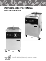
Operations and Service Manual
Model CF-401, CF-560 and CF-720
CF-401
CF-720
Chester Fried A Division of Giles Enterprises, Inc.
P.O. Box 210247 • 2750 Gunter Park Drive West • Montgomery, AL 36121-0247 USA • (334) 272-3528
SERVICE HOTLINE 1-800-288-1555 (USA and Canada only) • FAX (334) 272-3561 • www.chesterfried.com
Form No. 64651 (8/98)
Safety Precautions
For Your Safety
!
Do not store or use gasoline or other flammable vapors and liquids in the vicinity of this
or any other appliance!
!
WARNING
Improper installation, adjustment, alteration, service or maintenance can cause property
damage, injury or death. Read the installation, operating and maintenance instructions
thoroughly before installing or servicing this equipment.
Post In A Prominent Location
b
Table of Contents
I
Introduction........................................................................................................................ 1
1
1-1
1-2
1-3
1-4
Installation
Installation Instructions........................................................................................................ 2
Removal of Fryer From Crate.............................................................................................. 3
Ventilation of Fryers............................................................................................................. 3
Electrical Requirements....................................................................................................... 3
2
2-1
Operating Instructions
Operating Instructions ......................................................................................................... 5
3
3-1
3-2
3-3
3-4
3-5
3-6
3-7
3-8
Fryer Components and Their Functions
Control Panel ....................................................................................................................... 6
Electro-Mechanical Timer Control Panel ............................................................................. 9
Lower Cooking Area.......................................................................................................... 11
Cooking Vessel .................................................................................................................. 13
Cooking Computer Features ............................................................................................. 15
Computer Key Functions................................................................................................... 17
Cooking Computer Programmer ....................................................................................... 18
Mechanical Timer Operating Instructions ......................................................................... 20
4
4-1
4-2
4-3
Testing the Fryer
Proper Control Settings for Check-out.............................................................................. 21
Operational Check of Heating Elements........................................................................... 21
Operational Check-out of Filter Pump............................................................................... 22
5
5-1
5-2
5-3
5-4
Preparing the Fryer for Operation
Fryer Boil-Out Procedure................................................................................................... 24
Cleaning of Filter Pan/Replacement of Filter Pan ............................................................ 28
Operating Fryer Controls for Cooking ............................................................................... 30
Filtering the Fryer .............................................................................................................. 30
6
6-1
6-2
6-3
6-4
6-5
6-6
6-7
Cooking Instructions
Marinating Process............................................................................................................ 32
Batter Dipped Seasoning................................................................................................... 32
Breading............................................................................................................................. 33
Loading the Chicken.......................................................................................................... 34
Using IQF Chicken............................................................................................................. 34
Stirring the Chicken ........................................................................................................... 34
Preparing the Potatoes...................................................................................................... 35
c
Table of Contents
7
7-1
7-2
Troubleshooting
Control System with Cooking Computer.......................................................................... 36
Automatic Basket Lift and Oil Filtration System............................................................... 37
8
8-1
8-2
Parts
Parts List ............................................................................................................................ 38
Parts List—Filter Pan Models CF-401 and CF-560 .......................................................... 40
9
9-1
9-2
9-3
9-4
9-5
9-6
9-7
9-8
9-9
9 - 10
9 - 11
9 - 12
9 - 13
Wiring
Wiring Diagram Model CF-401 with Electromechanical Timer (3 Phase) ........................ 42
Wiring Diagram Model CF-401 with Electromechanical Timer (1 Phase) ........................ 44
Wiring Diagram Model CF-401 with Cooking Computer (3 Phase) ................................. 46
Wiring Diagram Model CF-401 with Cooking Computer (1 Phase) ................................. 48
Wiring Diagram Model CF-560 with Electromechanical Timer (3 Phase) ........................ 50
Wiring Diagram Model CF-560 with Electromechanical Timer (1 Phase) ........................ 52
Wiring Diagram Model CF-560 with Cooking Computer (3 Phase) ................................. 54
Wiring Diagram Model CF-560 with Cooking Computer (1 Phase) ................................. 56
Wiring Diagram Model CF-720 with Cooking Computer 208/240V (3 Phase)................. 58
Wiring Diagram Model CF-720 with Cooking Computer 480V (3 Phase)........................ 60
Wiring Diagram Model CF-720 with Electromechanical Timer 208/240V (3 Phase)........ 62
Wiring Diagram Model CF-720 with Electromechanical Timer 480V (3 Phase)............... 64
Wiring Diagram Model CF-720 with Electromechanical Timer 220/380V (3 Phase)........ 66
Introduction
Congratulations on the purchase of your new Chester Fried Electric Fryer. The Chester Fried Models CF401, 560 and CF-720 are equipped with a high quality cooking computer which is covered by a two year
warranty. This new “user friendly” easily programmable cooking computer incorporates extensive design
detail by its manufacturer WATLOW, and extensive cooking application by the “Chester Fried” engineering team. The new Cooking Computer along with the Chester Fried fryer is truly a “world class” product.
They are also available with an easy to use Electromechanical Timer.
To help protect your investment in this state-of-the-art cooking equipment, we recommend you take a
few moments to familiarize yourself with the installation, cleaning and maintenance procedures contained
in this manual. Adherence to these recommended procedures minimizes the potential for costly
”Down-Time“ and equipment repairs.
2
Installation Instructions
1 - 1 Installation Instructions
This section provides a summary of the procedures necessary for proper installation of your new Chester
Fried Electric Fryer. To prevent personal injury or equipment damage, please ensure that the following
steps are taken:
!
For your safety do not store or use gasoline or other flammable vapors and liquids in the
vicinity of this or any other appliance!
1.
Keep the appliance and surrounding area free and clear from combustible materials (minimum 4
inches) (10cm).
2.
Please retain this manual for future reference.
3.
Please note wiring diagrams for this appliance are located in the rear of this manual.
Ensure the wiring diagram, which you consult, corresponds to the model being operated.
4.
Please ensure this appliance is electrically grounded in accordance with local codes, or in the
absence of local codes, with the National Electrical Code, ANSI/NFPA NO. 70-1984.
5.
Please provide adequate room for servicing and proper operation of this appliance. Also, provide
adequate ventilation in the operating area where necessary.
6.
Always consult with an electrician or other qualified individuals prior to installation.
7.
Ensure voltage and amperage supplied to the unit are as specified on the fryer’s rating plate.
8.
Make sure this unit is in a secure position and will not move. Locking casters are supplied on this
unit—USE THEM!
9.
See electrical connection diagram in section 9 for wiring connection location.
IMPORTANT NOTE
The above steps will help to ensure safe and proper installation of your fryer. If you have any questions
concerning these procedures, contact your local Chester Fried distributor or other qualified service person.
!
Do not modify, alter or add attachments to this equipment!
3
Installation Instructions
1 - 2 Removal of Fryer from Crate
Your Chester Fried Fryer may arrive enclosed by a wooden crate. If your unit arrived uncrated, go to Section 1-3. The Fryer is secured to a wooden platform by means of high-tensile strength strapping.
1.
Carefully cut and remove the plastic shipping wrap and the strapping mentioned above.
2.
Use a hammer and a prybar to remove the wooden crate around the Fryer. Be careful not to
damage the Fryer.
3.
Open the cabinet door and remove the filter pan by pulling the pan straight out of the cabinet.
4.
Carefully remove the fryer from the shipping platform. Your new fryer is extremely heavy and great
care should be taken in lifting or moving the unit to prevent personal injury or equipment damage.
1 - 3 Ventilation of Fryers
Your new Chester Fried Electric Fryer has been designed for operation beneath a traditional exhaust
hood. We strongly recommend that you consult a professional ventilation or heating and air conditioning
company for assistance in designing a hood for those models which require an exhaust system.
IMPORTANT NOTE
Guidelines for proper ventilation system requirements may differ. Always consult with local authorities to
ensure compliance.
1 - 4 Electrical Requirements
!
WARNING
Equipment must be adequately and properly grounded. Improper grounding may result in
electrical shock. Always refer to your local electrical code to ensure proper grounding of
this or any other electrical equipment. Always consult with an electrician or other
qualified service person to ensure that breakers and wiring are of sufficient rating and
gauge for the equipment being operated.
Chester Fried Electric Fryers are available from the factory wired for 208, 240, or 480 volts, single and
three phase, (Note: CF 720 available in three phase only) 50/60Hz service, Delta only. Check the rating
plate on the rear of the fryer to determine the correct power supply.
4
Operating Instructions
2 - 1 Operating Instructions
For your safety, please observe the following precautions when operating your Chester Fried Fryer.
1.
Ensure the fry kettle is positioned in a secure safe location with the casters in the locked position.
2.
Consult an electrician to ensure all electrical specifications have been met and the unit is properly
grounded. The wiring diagrams contained in this manual should aid your electrician in the
installation of your fryer.
3.
Due to the high temperature of shortening in your fryer during cooking, it is extremely important
the user exercise caution in operating this equipment to avoid personal injury.
4.
DO NOT use solid shortening as a cooking oil. Doing so may damage the filtration system of the
fryer.
5
Fryer Components and Their Functions
3
Fryer Components and Their Functions
The following section is designed to introduce you to the controls used in operating this equipment.
DO NOT attempt operation of this unit until you have located each control discussed and fully understand
their function. Failure to do so may result in improper operation resulting in equipment damage or personal injury to the operator.
Please review this section carefully before proceeding any further.
Refer to the accompanying photographs for the location of the components discussed.
3 - 1 Electronic Controller Panel Components and Their Functions
ITEM
DESCRIPTION
FUNCTION
1. Fig. 1
Power Switch
The Power Switch is a two position switch. Move the
switch upward to the “ON” position.
2. Fig. 1
Cook/Filter Selector Switch
The Selector Switch is a three-position switch which
is used to select either the cook, off or filter mode of
operation. The fryer’s heating elements will only
operate in the “COOK” position. The switch should
be placed in the “Filter” position to filter the
shortening which will allow the pump to operate.
3. Fig. 1
Timer/Cooking Computer
Electronic timer for controlling cooking times.
4. Fig. 1
Power Indicator Lights
The Green Power Light is on whenever the fryer’s
Master Power Switch is in the “ON” position.
5. Fig. 1
Heat Indicator Light
The Orange Heat Indicator Light will be on whenever
the fryer’s heating elements are operating. When the
selected operating temperature is reached, the light
will go off.
6. Fig. 1
High-Limit Indicator Light
The High-Limit Indicator Light illuminates as a result
of power being shut-off to the fryer’s heating
elements by the built-in solid-state control circuit as a
safeguard against overheating. Should this light
come on during operation, refer to the troubleshooting section of this manual. NEVER COOK IN A
FRYER WITH THE HIGH-LIMIT LIGHT ON.
6
Fryer Components and Their Functions
Figure 1
4
6
3
2
1
5
7
Fryer Components and Their Functions
Figure 2
Electro-Mechanical Timer Control Panel
6
8
7
8
5
4
9
2
3
11
Fryer Components and Their Functions
3 - 2 Electro-Mechanical Timer Control Panel Components
and Their Functions
ITEM
DESCRIPTION
FUNCTION
1. Fig. 2
Power Switch
The Power Switch is a two-position switch. Move the
switch upward to the “ON” position for operation.
2. Fig. 2
Cook/Filter Selector Switch
The Selector Switch is a three-position switch which is
used to select either the cook, off or filter mode of
operation. The fryer’s heating elements will only
operate in the “COOK” position. The switch should be
placed in the “Filter” position to filter the shortening
which will allow the pump to operate.
3. Fig. 2
Electromechanical Timer
Electro-Mechanical timer for controlling cooking times
and basket lift operations.
4. Fig. 2
Timer Toggle Switch
The Timer Toggle Switch is a two-position switch. Flip
the switch to the right to the “ON” position to start
timer. (Flip the switch to the left at the end of the
cooking time to silence the buzzer.)
5. Fig. 2
Thermostat
Regulating Thermostat to set oil cooking temperature.
6. Fig. 2
Power Indicator Light
The Green Power Light is on whenever the fryer’s
Master Power Switch is in the “ON” position.
7. Fig. 2
Heat Indicator Light
The Orange Heat Indicator Light will be on whenever
the fryer’s heating elements are operating. When the
selected operating temperature is reached, the light
will go off.
8. Fig. 2
High-Limit Indicator Light
The High-Limit Indicator Light illuminates as a result
of AUTOMATIC POWER SHUT-OFF of the fryer’s
heating elements by the built-in solid-state control
circuit as a safeguard against overheating. Should this
light come on during operation, refer to the
troubleshooting section of this manual. NEVER COOK
IN A FRYER WITH THE HIGH-LIMIT LIGHT ON.
9. Fig. 2
Basket Up/Down Momentary
Switch
Used to raise and lower basket.
9
Fryer Components and Their Functions
Figure 3
Lower Cabinet Area
3
4
10
5
2
6
Fryer Components and Their Functions
3 - 3 Lower Cabinet Area Components and Their Functions
ITEM
DESCRIPTION
FUNCTION
1. Fig. 3
Hold-Down Bracket (Not Shown)
The Hold-Down Bracket is contained in the filter pan
and serves to ensure the filter paper is held tightly in
place by means of the four locking latches. The
fryer’s filtering action will be reduced or eliminated if
these latches are not properly secured.
2. Fig. 3
Drain Valve Lever
Turning this handle counter-clockwise allows
shortening to drain from the frying vessel into the
filter pan. Open the valve slowly to avoid burns from
splashing of hot oil. Always ensure the valve is
closed prior to adding shortening. Your fryer will not
operate if this drain valve is not completely closed.
(i.e., clockwise) ENSURE THE FILTER PAN IS
FULLY INSERTED INTO THE FRYER BEFORE
OPENING DRAIN VALVE TO PREVENT
SPLASHING OF HOT OIL.
3. Fig. 3
Oil Discharge Fitting
This Quick-Disconnect Fitting is used in conjunction
with the oil discharge wand to remove oil from the
fryer that is to be discarded.
4. Fig. 3
Diverter Valve Lever
The diverter valve lever is located on the left side of
the inner cabinet panel. During normal operation it
should be positioned so that it points upward. For
removal of oil with the discharge hose connected,
the diverted valve handle should be turned to the
left. After removal of oil for discard, it should be
returned to its normal position pointing upward.
Details of the oil procedure are covered in the
operations section of this manual.
5. Fig. 3
Oil Return Fitting
This quick disconnect fitting serves to connect the
filter pan to the fryer’s oil return lines. The fitting is
disconnected by pulling the filter pan from beneath
the fryer. To reconnect, push the filter pan under the
fryer until fitting docks.
6. Fig. 3
Filter Pan
The Filter Pan contains the filter paper which serves
to remove breading and other impurities from the oil
during the filtering procedure. Oil is drained into the
filter pan where the fryer’s pumping action draws it
through the filter paper and returns it to the cooking
vessel. The pan slides outward for cleaning or
removal.
7. Fig. 3
Oil Discharge Wand (Not Shown)
The Oil Discharge Wand is used to remove old oil
from the fryer.
11
Fryer Components and Their Functions
Figure 4
Cooking Vessel
5
1
4
12
2
Fryer Components and Their Functions
3 - 4 Cooking Vessel
ITEM
DESCRIPTION
FUNCTION
1. Fig. 4
Oil Temp Probe
The Oil Temp Probe senses oil temperature during
fryer operation for temperature control. Its signal is
directed to the fryer’s control unit for comparison with
the temperature selected by remote set-pot on the
operator.
2. Fig. 4
Heating Element
The Heating Element heats the shortening to the
selected temperature. Always maintain the cold oil
level above the heating elements to prevent oil fires!!
3. Fig. 4
Basket Carrier (Not Shown)
The Basket Carrier is placed over the elevator shaft
and allows for positioning and control of the basket in
the fryer using the elevator lift.
4. Fig. 4
Oil Return Inlet
The Oil Return Inlet serves to return oil to the frying
vessel following filtering.
5. Fig. 4
High-Limit Probe
The High-Limit Probe senses oil temperature during
fryer operation for oil overheating. If the sensor
detects an oil temperature in excess of 424°F (218°C),
the solid-state control system will turn off power to the
heating elements.
6. Fig. 4
Oil Level Line (Not Shown)
The Oil Level Line marks the proper level of HOT
shortening. When COLD, the shortening will be
approximately 1⁄4 inch (.64cm) below the Oil Level Line.
The proper shortening level is important and should
be checked a minimum of once per day.
13
Fryer Components and Their Functions
Figure 5
Electronic Controller
1
14
2
Fryer Components and Their Functions
3 - 5 Cooking Computer Features
To help you understand the many programming features of the cooking computer, we strongly suggest
you read the following:
1.
Cool Down Cycle
After any of your 8 menu time cycles end (00:00) and your fryer is not required for use for an hour
or more, you can reduce energy cost by pressing the “COOL” key. This key will allow the hot oil to
cool down to 275° F (135° C) for stand-by use. When your fryer is required for use after being in the
“cool” cycle, merely press the COOL key again and the fryer will go back to the last lighted menu
key’s programmed temperature. When the orange heat light goes off in approximately 3-4 minutes,
stir the oil. After the light goes out a second time, the fryer will be ready for use.
2.
Filter Cycle and Alarm
The Chester Fried chicken program recommends that every fourth full load of chicken you filter
your oil. Filtering cleans the breading settlement out of the fry pot and removes contaminants from
the oil. The filtering process can greatly extend the oil life. At the end of every fourth load “FILT”
will flash up on the display and a repeating 2 seconds on/2 seconds off sound alarm will be heard.
The filter alarm indicates it is time to filter the oil.
NOTE
The sound alarm can be silenced by pressing the “FILTER” key.
3.
Stir Cycle and Alarm
Your fryer is equipped with a stir message and a repeating one second on/one second off sound
alarm telling you it’s time to stir your product. This feature is a Chester Fried preset time of 62% of
each of the 8 menu times previously set to prevent the chicken from sticking to itself. When the stir
alarm sounds, stir the chicken and then silence the alarm by pressing the lighted menu key once.
4.
End of Menu and Alarm
At the end of any menu 1-8, the 10 second long continuous alarm can also be silenced prior to the
10 second ending by pressing the lighted menu key once. When counting down time without the
alarm sounding, pressing the lighted menu key will reset that menu key to 00:00. You cannot raise
the basket when canceling out a menu in progress by pressing the lighted menu key and then the
up arrow!
Your cooking computer has many various capabilities to meet many special end user needs. Our
service department at 1-800-288-1555 stands ready to answer special questions. We can give
you multiple cooking temperatures and times (up to three) per menu item for special products.
We can adjust the end of menu alarm, both loudness and sound pattern. We can also easily give
you time compensation, as well as several other special performance items only a world class
computer can perform!
15
Fryer Components and Their Functions
Figure 6
Program Menu
2
1
4
16
1
3
Fryer Components and Their Functions
3 - 6 Computer Key Functions
The following is a description of the basic function and operation of your cooking computer’s key pad.
Basket Key
When the basket key is pressed once, the up and down arrow keys blink. If the basket is up, it can only
be lowered using the down arrow ( ) key. Once the basket key is pressed you have 20 seconds to
select your basket arrow direction or you must push it again after the basket key light goes off. Once
the basket key is pressed and the proper arrow key is pressed within 20 seconds, the basket travels
either up or down. Any menu cycle can be started while the basket is in motion. The basket cannot
be stopped during it’s up or down travel. Allow 20 seconds for the basket travel time to change bas
ket direction of travel if required.
2.
Temperature Bulb Key
To check the temperature setting of any lighted menu key, simply press the Temperature Bulb Key and
for 3 seconds the temperature will display and then return to 00:00 or the time remaining in that menu
countdown.
3.
Boil Cycle Key (For use with boil out procedure portion of this manual only)!
The boil cycle feature is used for cleaning the fryer by using fryer heated cold water & Chester Clean
(part #71425). When the Boil key is pressed and held for 5 seconds, and no menu is active (00:00), the
red boil light will come on and the display will alternately flash boil and 00:00 This activates a fixed
temperature setting of 200°F (93°C). The water and Chester Clean will not boil at 200°F (93°C) but it
will clean the fry pot and keep the Boil-out solution from possible boiling over on the floor.
a. When this cycle is considered complete (fryer clean) turn off the fryer power rocker switch.
b. Drain and wash out the fry pot.
c. Refill with room temperature oil to 1/4” (.64cm) below the oil line before turning the fryer on!
When the fryer is turned on, the computer will heat the oil to the menu 1 key temperature. To heat it
to a different menu key temperature, merely press your desired menu key twice.
4.
Menu Keys 1 Through 8
At the end of any menu 1-8, the 10 second long continuous alarm can also be silenced prior to the 10
second ending by pressing the lighted menu key. When counting down time without the alarm
sounding., pressing the lighted menu key will reset that menu key to 00:00. You cannot raise the
basket when canceling out a menu in progress by pressing the lighted menu key! The basket can only
be raised by pressing the basket key and then the up arrow ( )!
➔
➔
1.
17
Fryer Components and Their Functions
3 - 7 Cooking Computer Programmer
The first step is to determine the time and temperature for each product. The recommended temperatures
for fried chicken are 335° F (168° C). Channel 1 is the only menu key programmed for 335° F (168° C) and
10:30 minutes when you receive your fryer. All other menu keys will require programming or reprogramming. Menu keys 2 thru 8 will be pre-set to 200° F (95° C) for 00:00 time and cannot be accessed to cook
on until programmed.
18
Fryer Components and Their Functions
Figure 8
Front Panel Mechanical Timer
19
Fryer Components and Their Functions
3 - 8 Mechanical Timer Operating Instructions
Turn power switch on.
2.
Make sure selector switch is in “COOK” position.
3.
Set temperature dial (thermostat) to desired cooking temperature (335° F/168° C). “HEAT” light will
come on until oil has reached set temperature.
4.
When the heat light goes out, lower the basket by pressing the down arrow ( ) on the basket
“up/down” switch.
5.
Before placing product in the fryer, stir the oil and wait for the heat light to go off again.
6.
Place product in the basket using caution not to splash hot oil when adding product to the basket.
7.
With timer switch in “OFF” position, turn timer dial to desired cooking time.
➔
1.
IMPORTANT NOTE
Do not set timer while switch is in “ON” position; doing so will damage the timer.
8.
Turn timer switch to “ON” position.
9.
Halfway through cook cycle, stir chicken to ensure even cooking of all pieces.
10.
At end of cycle, the timer will activate a buzzer and raise the basket automatically.
11.
To turn buzzer OFF or reset timer, turn timer switch to “OFF” position.
20
Testing the Fryer
4
Testing the Fryer
We at Chester Fried take pride in the quality of our workmanship. Every effort has been made to ensure
that your unit is in good operating condition when you receive it. Each unit must pass a rigorous quality
control test prior to shipment. To further ensure optimum operation of your new unit, we recommend a
brief operational check-out of your new fryer.
!
CAUTION
Before attempting to operate the unit, refer to Section 3-1 to familiarize yourself with the
various control functions. Once you have read and fully understand Section 3-1, please
follow the steps below precisely in order to prevent equipment damage or malfunction.
4 - 1 Proper Control Settings for Check-Out
1.
Place all switches in the “OFF” position.
2.
Remove fryer lid.
3.
Remove the baskets or other accessory items from the fry-kettle.
4.
Turn on the circuit breaker which supplies power to the unit.
5.
Place the fryer’s main power switch to “ON.” The green power light should be illuminated. If the
power light fails to illuminate, refer to the troubleshooting guide, see section 7. If the green power
light illuminates, proceed to the next step.
4 - 2 Operational Check of Heating Elements
This step is designed to ensure that your fryer’s heating elements are functioning.
!
WARNING
DO NOT touch the heating elements during this portion of the check-out. The heating
elements are very hot and skin contact with them may result in severe burns.
1.
Wipe the dry cool heating elements with a wet sponge.
!
CAUTION
This portion of the check-out requires that the elements be activated. DO NOT operate
the elements for more than ten seconds without them being fully covered by shortening.
Failure to observe this precaution may result in damage to the heating elements.
1.
2.
With the fryer’s lid removed, briefly turn the Selector switch to the COOK position (max. 10 sec.).
Then return it to the OFF position.
The wet element should dry within 15 seconds after fryer element shut-off signifying heat.
21
Testing the Fryer
3.
If the elements are not operational, refer to the troubleshooting guide in section 7.
4.
If the heating elements are operational, clean the fryer as described under the instructions for the
boil-out procedure described in Section 5-1.
5.
After thorough cleaning, fill fry pot to proper level with shortening.
4 - 3 Operational Check of Filter Pump
1.
Open the fryer’s front door.
2.
Disconnect the filter-pan by removing the filter pan from beneath the fryer.
!
CAUTION
The following step requires starting the fryer’s filter pump in a “DRY” condition. The
pump should only be operated for a few seconds in this manner or damage to the unit
may occur.
3.
Place the fryer’s power switch to the “ON” position.
4.
Place your palm over the quick-disconnect at the point where the fitting from the filter pan
connects.
5.
Briefly place the Selector switch in the “Filter” position. If suction is felt on the hand covering the
quick-disconnect, the pump is operational. If the above steps are followed and no suction is felt,
consult the troubleshooting guide.
22
Testing the Fryer
Figure 9
Lower Cabinet
23
Preparing the Fryer for Operation
5
Preparing the Fryer for Operation
Your new fryer should be cleaned thoroughly before actual cooking takes place. To accomplish this, follow
the procedure described in the following Boil-Out Procedure Section.
5 - 1 Fryer Boil-Out Procedure
This section describes the cleaning process for your fryer known as the “Boil-Out.” A “Boil-Out” should
be performed on new equipment prior to actual cooking and every time shortening is removed from the
fryer for cleaning of the fry-kettle and refill with fresh shortening.
!
WARNING
Please perform the steps of this procedure as described to avoid possible equipment
damage, violation of warranty provisions or personal injury.
1.
Always use thermal oven mitts during this procedure to protect skin from burns due to splashing of
hot liquids.
2.
If you are performing a “Boil-Out” on a new fryer which does not contain shortening, go to Step 19;
otherwise, proceed to Step 3.
3.
If the shortening in the fryer is not in a heated state (at least 200°F/93°C), go to Step 4. If the fryer has
been in operation and the shortening is in a heated state, place the Selector switch in the “OFF”
position and allow the shortening to cool for two minutes before continuing.
4.
If the shortening in the fryer is “Cold,” that is at room temperature, you must first heat the
shortening briefly so that it is liquid enough to be removed by the fryer’s filter system. To do this, turn
the main power switch to “ON” and the Selector switch to “Cook.” Turn the temperature select knob
to 200° F (93° C)and heat the oil until the orange heat indicator light goes out. Stir the shortening well
to ensure it is fully dissolved. Stirring may cause the orange heat light to come on again briefly. When
the orange light goes off again, place the Selector switch in the “OFF” position and go to Step 5.
5.
Ensure the selector switch is in the “OFF” position before proceeding.
!
WARNING
The next step of this procedure requires the shortening be drained from the fry-kettle into
the fryer’s filter pan. Failure to ensure the fryer’s Selector switch is in the “OFF” position
prior to draining may result in fire on the exposed heating elements. Always ensure the
Selector is in the proper position.
6.
24
Slowly open the Drain Valve Lever located on the drain beneath the fry-kettle. The drain is opened
by turning it counter-clockwise. Use care in operating this valve to avoid being splashed by hot oil.
(You may find the drain requires insertion of the smaller brush enclosed with the fryer in order to
free the valve of breading, which may clog it. The brush should be inserted from above. Be careful
not to puncture the filter paper when using this brush.)
Preparing the Fryer for Operation
7.
Ensure the diverter valve is positioned so its handle points upward.
8.
Place Selector switch in the “Filter” position and allow shortening to return to the fry-kettle and out
through the drain. Use this opportunity to “Wash-Down” breading which has accumulated in the
bottom of the fry-kettle. Use the larger pot brush supplied with the fryer to help “Wash Down” this
material into the filter-pan below. Use care to avoid being splashed and burned by the hot oil.
9.
After “Washing Down” all accumulated breading and crumbs from the bottom of the fry-kettle,
place the Selector switch in the “Off” position and allow the shortening to drain into the filter pan.
10.
Turn the Drain Valve Lever on the drain valve clockwise to close.
11.
Position an appropriate receptacle for the oil you are to discard near the front of the fryer. Remember,
you will be removing approximately 121/2 gallons (41.5L) of shortening. Please ensure that the
container which you have selected will contain all of the shortening. For ease in handling, you may
find it helpful to use more than a single container. The shortening you will remove weighs about
80lbs. (36.4kg) and is still very hot. Placing the discarded shortening in two or more containers for
removal makes for a lighter load and decreases the possibility of injury by splashing. We recommend
our Oil Caddy (#79229A) for this purpose.
!
WARNING
Always ensure the containers which are used for this step will safely hold hot oil. Plastic is
generally not safe as it may melt and break. Metal containers which do not leak are
preferable to containers made of other materials. Failure to exercise the above precautions
may result in serious injury.
12.
Connect the discharge drain hose to the quick disconnect located beside the diverter valve. Always
ensure the hose coupling is securely mated at the quick disconnect fitting.
13.
Turn the handle on the diverter valve to the left (Counter Clockwise).
!
CAUTION
Do not run boil-out through the filter pump. Doing so can damage the pump and the void
warranty.
14.
Position the hand-held wand end of the discharge hose over the receptacle which you have
positioned to receive the HOT waste oil from the fryer. Always grasp the discharge hose by the
insulated sleeve near the wand end.
15.
Place the Selector switch in the “Filter” position and allow the fryer filter system to pump the HOT
waste oil out of the fryer through the drain hose.
16.
When all waste oil has been removed from the fryer, return the Selector switch to the “OFF” position.
17.
Return the diverter handle to its normal position so it points upward.
25
Preparing the Fryer for Operation
Figure 10 Filter Pan without Drain Hose
26
Preparing the Fryer for Operation
18.
Disconnect the drain hose from the fryer at the quick disconnect fitting beside the diverter valve.
Always hold both ends of the drain hose in an upright position to avoid spillage of residual oil which
may be trapped in the hose. Carefully drain the hose into the receptacle which contains the waste oil
from the fryer.
19.
Slide the filter pan forward and carefully remove it for cleaning.
NOTE
We recommend that you use Chesterclean or an alkaline based cleanser to clean the filter pan.
Avoid dish washing detergents as they may leave residues which reduce shortening life.
20.
Ensure the drain valve is closed by turning the drain valve lever fully clockwise.
21.
Fill the fryer with water to the Oil Level Line.
22.
Carefully add Chesterclean to the water following the directions on the container.
!
CAUTION
If you choose to use a cleaner other than Chesterclean to “Boil-Out” your fryer, pay close
attention to the instructions listed on the container. Many commercially available cleaners
are caustic chemicals which require special precautions for use. If used improperly, these
chemicals may cause damage to your fryer and potential injury to the user.
23
Push and hold the “Boil” key for 5 seconds.
!
CAUTION
Do not under any circumstances leave the fryer unattended during this procedure as heat
must be carefully monitored to prevent the fry-kettle from overflow due to boiling.
Overflow of the fry-kettle may result in serious equipment damage. In the event of near boil
over, flip the power switch off!
24.
Set the selector switch in the “Cook” position.
25
Heat the cleaning solution for 30 minutes. Scrub the interior of the fry-kettle with the large pot brush
during this period to remove build-up.
26.
Flip selector switch to the off position.
27.
Position a heat resistant pail beneath the drain valve at the bottom of the fry kettle. Slowly open the
valve by turning the drain valve lever counter-clockwise. Drain the cleaning solution from the fryer.
Be careful not to overfill the container which will hold the cleaning solution drained from the fryer.
28.
Close the drain valve by turning the Diverter Valve Handle fully in a clockwise position.
29.
Rinse the inside of the fry-kettle with fresh water and repeat the drain procedure described
above in step 27.
27
Preparing the Fryer for Operation
30.
Mop out excess water from the fryer pot with a dry cloth.
31
Close the drain valve again.
32.
Replace filter pan after thorough cleaning.
IMPORTANT NOTE
Do Not pump “Boil-Out” thru filter pump. Doing so can damage pump and void warranty.
33.
Fill fryer with shortening to the proper level. Shortening should reach the Oil Level Line when the oil
is HOT.
5 - 2 Cleaning of Filter/Pan Replacement of Filter Paper
The following steps should be taken with the filter pan removed from the fryer. The filter pan should be
thoroughly cleansed during each “Boil Out” procedure. Do not attempt to clean the Filter Pan when pan
is still in fryer cabinet.
1.
Remove accumulated breading and residue from the surface of the filter paper with the metal
crumb shovel supplied with the fryer. Remove residue from the small edge which surrounds the
Hold-Down frame.
2.
Release the four Hold-Down latches which secure the frame which holds the filter paper in place.
3.
Remove the Hold-Down frame from the filter pan and place it in the sink for cleaning.
NOTE
Use only Chesterclean or a suitable alkaline based cleaner to clean the Hold-Down frame as well
as the other interior surfaces and components of the filter pan. Liquid dish washing detergents
may leave residues which reduce shortening life.
4.
Beginning at one end of the filter pan, carefully roll up the filter paper and throw it away.
5.
Remove the wire rack beneath the filter paper and place it in the sink for cleaning.
6.
Drain any remaining oil from the bottom of the filter pan into a proper waste receptacle. You must
lift and tilt the filter pan to accomplish this. The filter pan is heavy, so you should have assistance.
7.
Clean the interior of the filter pan with one of the cleaners previously recommended.
8.
Clean and rinse the wire rack and Hold-Down frame which you placed in the sink earlier. Dry them.
The filter pan is now ready for re-assembly and installation of new filter paper.
Two sheets of paper are used in the filter pan. The filter pan must be removed from the fryer to change the
filter paper. Both sheets should be changed following a “Boil-Out.” During normal operation, the top sheet
is discarded on a daily basis. The bottom sheet is then placed on top of a new sheet of filter paper and the
filter paper is replaced in the filter pan with the Hold-Down frame. The following simple steps summarize
the procedure for replacement of the filter paper on a daily basis.
Daily filter paper replacement is recommended!
28
Preparing the Fryer for Operation
Figure 11 Disassembled View of Filter Pan; All Models
Instructions for changing the Filter Paper:
1.
Remove the crumb and breading residue which surrounds the Hold-Down rack that secures the filter
paper in place.
2.
Remove crumbs and breading residue from the top sheet of filter paper with the metal crumb
shovel supplied with the fryer.
3.
Release the four Hold-Down latches on the frame assembly which secures the filter paper.
4.
Remove the Hold-Down Frame.
5.
Carefully remove the top sheet of filter paper by lifting its corner or edge and rolling it towards the
other end. Discard the paper.
6.
Lift the edge of the bottom sheet and slip a clean sheet of filter paper beneath it.
7.
Replace the Hold-Down rack above the filter paper and secure it with the four latches.
8.
Replace the filter in the fryer and ensure that the filter is properly docked.
29
Preparing the Fryer for Operation
5 - 3 Operating the Fryer’s Controls for Cooking
Before cooking with the fryer, ensure that you have read and fully understand the intended functions of
each control used on the fryer. Detailed explanations are found in Section 3 of this manual.
1.
2.
Fill fryer with shortening approximately 1⁄4 inch (.64 cm) below the oil level located at the back of the
fry kettle. The oil level line is for “Hot” shortening and additional shortening can be added after
heating if necessary.
Place the fryer’s power switch in the “ON” position. (The green power light should come on.)
3.
Place the Selector switch in the “Cook” position.
4.
Use the Cook keys to select the desired cooking temperature. The orange heat light will glow as the
oil is heated to the proper temperature. When the orange light goes out, stir the shortening vigorously
to ensure it is completely heated. Stir the shortening until the orange light comes on again.
5.
When the orange light goes out for the second time, the shortening will be at the selected cooking
temperature.
6.
Properly secure the fry basket to the basket carrier mounted to the fryer’s elevator shaft.
7.
Push the elevator Down Key. This will lower the basket into the heated shortening.
8.
Carefully drop breaded food product into fry basket. Avoid splashing hot shortening.
NOTE
Food products should be placed in the fry basket after it is lowered into the hot oil. This prevents
them from sticking together. If the products to be cooked are frozen, they can be placed in the fry
basket before lowering it into the shortening.
9.
Push the desired menu key on electronic timers or set timer on mechanical timers to start the timing
cycle.
10.
Place the fryer lid in its proper position on the fry-kettle. Note - If you are cooking products which are
not frozen, it is a good idea to remove the lid and stir the food with the stir paddle supplied with the
fryer when the stir alarm sounds. This will help keep the food products from sticking together.
11.
If you have removed the fryer lid to stir the food products, replace it and allow the cooking cycle to
be completed.
12.
Remove the lid, dump the fry basket into a suitable container (LT Pan Part #79592), and prepare for
the next load.
5 - 4 Filtering the Fryer
The fryer should be filtered after every fourth load.
1.
30
Use thermal oven mitts during this procedure to prevent burns from hot oil and metal surfaces of the
fryer.
Preparing the Fryer for Operation
2.
Ensure filter paper (2 pieces) is properly positioned in the filter pan as described in Section 5 under
the section detailing replacement of the filter paper.
3.
Place the selector switch in the “OFF” position.
!
WARNING
Failure to ensure the selector switch is in the “OFF” position during procedure may result
in equipment damage and/or personal injury.
4.
Spread 12 ounces (.34 kg) of Chester Fried filter powder in the filter pan. The filter powder helps
extend shortening life by removing impurities.
5.
Allow the shortening to cool for 3 minutes after adding the filter powder.
6.
Ensure the filter pan is properly docked in the fryer.
7.
Slowly open the Drain Valve Lever by turning counter-clockwise. Be very careful to avoid being
splashed by hot oil.
8.
Use the smaller diameter brush included with the fryer to open any clogs which might develop as you
drain the oil into the filter pan.
!
CAUTION
Be careful not to puncture the filter paper when using the brush to unclog the drain valve.
9.
Ensure the lever-type handle which controls the diverter valve is in the proper position for the
filtering operation. The handle should be positioned so it is pointed upward.
10.
Place the selector switch in the “Filter” position.
11.
Leave the drain valve open and allow the filtered shortening to return to the fry-kettle and drain out
the bottom through the drain valve. Use the larger brush included with the fryer to “Wash-Down” the
fry-kettle and heating elements with the hot shortening as it circulates through the fry-kettle.
Continue this for 3 minutes.
12.
Close the drain valve completely by turning the drain valve lever in a clockwise direction. Failure to
close down completely will prevent fryer from operating.
13
Allow the filtered shortening to return to the fry-kettle. The oil will begin to bubble as the pumping
action is completed and the air fills the oil return lines. Place the selector switch in the “OFF”
position.
14.
Ensure the fryer contains the proper shortening level (See Oil Level Line).
15.
Place the Selector switch in the “Cook” position, push a cook key and allow shortening to reach the
proper cooking temperature.
31
Cooking Instructions
6 - 1 Marinating Process
Marinating is the process by which salt and special spices are absorbed into the tissue to enhance the flavor of the chicken. This procedure is one of the primary factors that accounts for Chester Fried’s remarkable taste appeal. Therefore, the marinating process must be implemented and with maximum efficiency.
The Marinating Procedure:
• Draws blood from the chicken.
• Tenderizes the meat.
• Raises the moisture content and the weight of the bird 10 to 12%.
• Allows the flavoring to be absorbed into the tissue of the meat in order to enhance the flavor of
the chicken.
• Helps reduce bacteria build up.
Recommended Marinating Procedure
1.
Take 3/4 cup (177ml) of Chester Fried Marinade and mix thoroughly with 3 gallons (11.4L) of cold water.
2.
Always press the bone through the thigh and fold the wings before marinating them.
3.
Place the chicken pieces in the solution and let them soak for 12 to 18 hours at 38°F (3.3°C).
4.
Remove the chicken from the marinade water.
5.
Rinse chicken with cold tap water and place in proper storage container with colander.
6.
Place a thin layer of ice on top of the chicken and store at 38°F (3.3°C).
!
CAUTION
DO NOT allow the chicken to marinate over 18 hours.
6 - 2 Batter Dipped Seasoning
The batter dip procedure is a very important bridge between marinating and breading. The batter seasoning accentuates the flavor of the meat and breading, and ensures the breading will stay on the chicken during the frying process.
• Mix 3 cups (708ml) of Chester Fried Batter Dip with 3 gallons (11.4L) of COLD water.
NOTE:
When using the Chester Fried Bread and Batter Table, use 3 gallons (11.4L) of Batter Dip in the
Dipper Well.
!
CAUTION
Change the batter after dipping 140 lb. (63.5kg) of the poultry.
32
Cooking Instructions
6 - 3 Breading
Breading is the final step before frying . Chester Fried Breadings have been blended according to strict standards and are formulated for great taste.
1.
Lightly dust the chicken in the breading mix.
2.
Place the chicken back in the Batter Dip Seasoning. Totally immerse the pieces in the Batter Dip two
times coating the chicken with this solution. Allow the chicken a few seconds to drip and dump the
pieces in the breading container.
3.
Thoroughly roll the pieces in the Chester Fried Breading, coating every crevice. Then, place them
on the Staging Tray.
Fig. 1
!
CAUTION
Fig. 2
Fig. 3
NEVER allow the chicken to be breaded in advance of frying. Allowing the chicken to be
pre-breaded and sit on a shelf, counter or staging tray of the batter table too far in
advance will create and unfavorable hard exterior on the finished product. Excessive time
between breading and frying the chicken allows the batter dip, which is water based to
penetrate the exterior breading creating a shell effect which ultimately produces an
offensively hard exterior.
33
Cooking Instructions
6 - 4 Loading the Chicken
The weight of the chicken will determine the quantity the cooker can accept and the specific cook time.
The approximate weight of each bird is 23/4 lb. (1.2k). (See chart for product amount)
Piece
MGF-20
Thigh
Legs
Breast
Wings
5
5
5
5
Total
20
MGF-40
MGF-50
CF-401
CF-560
CF-720
10
10
10
10
12
12
12
12
10
10
10
10
14
14
14
14
18
18
18
18
40
48
40
56
72
Dark meat has a higher moisture content than white meat. To guarantee proper cooking, load the dark
meat ahead of the white meat. Dark meat is the Thigh (large) and the Leg (small). White meat is the
Breast (large), and Wing (small).
Loading Sequence:
1.
2.
3.
4.
Thighs
Legs
Breast
Wings
6 - 5 Using IQF and Pre-Marinated Chicken
Model ..........................
Cooking Minutes ........
Cooking Temperature
MGF-20
13
MGF-40
MGF-50
CF-401
CF-560
13
13
10.5
10.5
Above Models 335°F (168°C)
CF-720
13
Good results can be obtained using a marinated IQF or a “pre-marinated” chicken product rather than
fresh chicken. Use of a “pre-marinated” product eliminates the need for marinating at the store level. The
IQF product should be thawed and processed in the same fashion as fresh chicken.
6 - 6 Stirring the Chicken
In order to protect the exterior coating desired by your customer, your fryer is equipped with a stir message and a repeating one second on/one second off sound alarm telling you it’s time to stir your product.
This time is a Chester Fried preset time of 62% of each of the 8 menu times to prevent sticking. When
this time occurs:
1.
Remove the Lid.
2.
Take the stir paddle and gently, stir the chicken and then silence the alarm by pressing the lighted
menu key once.
34
Cooking Instructions
6 - 7 Preparing the Potatoes
The preparation for the potatoes plays a vital role in the success of your Chester Fried operation. We suggest that you use a white Idaho potato, 80 count in size. The Idaho potato comes out of the fry-kettle as
light and golden in color as your fried chicken. It has a longer shelf life and holds its color better in the
warmer than other potatoes, such as the Russet.
However, there are many different potatoes available on the market; and, local testing is the only sure way
to satisfy your customers.
Potato Wedges
1.
Scrub the potato and run it through the slicer. We have found that the potato is in its most desirable
state for frying when cut into an eight piece wedge. Some have attempted to cut the potato into a four
piece wedge but our research has shown the eight-piece cut to be more desirable in texture and
flavor.
2.
Drop the wedges into a fresh marinating solution.
!
CAUTION
DO NOT marinate the chicken and potatoes in the same container. DO NOT use the same
marinade solution more than once. The potatoes need to soak 12 to 18 hours in the
solution to give it that Chester Fried flavor
3.
Remove the potato wedges from the marinade water and rinse with fresh cold water.
4.
Lightly dust the potato wedges in the Breading Mix.
5.
Place the wedges in the Batter Dip Seasoning Mix. Totally immerse them in the Batter Dip two times.
6.
Thoroughly coat the wedges with the Breading a second time and place on Staging Tray.
7.
Place them in the fryer for 7 minutes at 335°F (168°C).
!
CAUTION
After marinating potatoes, add fresh water to potatoes until ready for use.
35
Troubleshooting
7 -1 Temperature Control System with Cooking Computer; All Models
Problem
Probable Cause
Repair Procedure
FRYER WILL NOT TURN ON:
No power light.
A. Not connected to power source.
B. Bad fuse or circuit breaker.
C. Fuse holder cracked.
D. Power switch bad.
E. Improper supply voltage.
A. Connect to proper power source.
B. Check fuse or breaker.
C. Replace fuse holder.
D. Replace power switch.
E. Connect to proper voltage source.
FRYER WILL NOT HEAT:
Power light on. Heat light not on.
A. Selector switch not in cook position.
A. Place selector to switch in cook
position.
FRYER WILL NOT HEAT:
Power light on.
Selector switch in cook position.
Heat light on.
A. Selected Menu Key programmed.
below present oil temperature.
B. Drain valve open.
C. Oil level too low.
D. Variable probe shorted or open.
E. Loose wire.
F. Contactor failure.
G. Element bad.
H. Selector switch bad.
A. Set Temperature Controller to
desired temperature.
B. Close drain valve.
C. Fill to oil level.
D. Replace probe.
E. Repair loose wire.
F. Replace faulty contactor.
G. Replace element.
H. Replace Selector switch.
FRYER WILL NOT HEAT:
Power light on.
Selector switch in cook position.
High Limit light On.
A. Power surge.
B. Plug not completely in.
C. Oil level too low.
D. Sticking contactor.
E. Bad high limit board.
F. High limit probe short or open.
G. Line spikes or noise.
A. Turn power switch off for 5 sec.
B. Reconnect to power source.
C. Fill to kettle oil level mark.
D. Replace contactor.
E. Replace high limit board.
F. Replace
G. Filter line or remove noise source.
FRYER HEATS SLOW:
(Slow Recovery)
Heat light stays on.
A. Incorrect cooking procedures.
A. Consult operations manual for
proper cooking procedure.
B. Replace bad element.
C. Replace contactor.
D. Repair loose wire.
E. Supply proper voltage.
B. Element failing.
C. Contactor failing.
D. Loose wire.
E. Low supply voltage.
FRYER HEATS SLOW:
(Short Cycling)
Heat light blinks off and
on continuously.
A. Low supply voltage.
B. Variable probe touching element.
C. Cooking computer faulty.
A. Supply proper voltage.
B. Reposition variable probe.
C. Replace Cooking computer.
* Call Tech Service Dept.
OIL TEMPERATURE ERRATIC:
Power light on.
Selector switch in cook position.
High Limit light On.
A. Probe bad.
B. Contractor failing.
C. Temperature controller faulty.
D. Loose wire.
A. Replace probe.
B. Replace contactor.
C. Replace controller.
D. Repair loose wire.
OIL SMOKING:
A. Old oil.
B. Over temperature.
C. Dirty element.
D. Element failure.
E. Improper element voltage.
F. Low oil level.
A. Change oil.
B. Check temperature control system.
C. Clean elements.
D. Replace element.
E. Supply proper voltage.
F. Keep oil at oil level line.
36
Troubleshooting
7 -2 Automatic Basket Lift and Oil Filtration System; All Models
Problem
Probable Cause
Repair Procedure
BASKET WILL NOT GO UP OR DOWN:
No power light.
A. Power not on.
B. Selector switch not in cook position.
C. Timer/Cooking computer faulty.
D. Elevator micro switch out of adjustment.
E. Elevator micro switch bad.
A. Turn power switch to on position.
B. Place Selector switch in cook position.
C. Replace faulty Timer/Cooking computer.
D. Adjust micro switch.
E. Replace micro switch.
BASKET WILL NOT GO UP OR DOWN:
A. Basket over loaded.
B. Elevator binding (slide bar dirty).
C. Bad elevator motor capacitor.
D. Drive sprocket set screw loose.
A. Put less product in basket.
B. Clean slide bars.
C. Replace elevator motor capacitor.
D. Tighten drive sprocket set screw.
BASKET CYCLES CONTINUOUSLY:
UP AND DOWN
A. Micro switch out of adjustment.
B. Selector switch bad.
A. Adjust micro switch.
B. Replace Selector switch.
OIL NOT RETURNING TO VAT:
A. Cook/Filter switch not in ”filter” position.
B. Air leak (hose, fittings, filter paper).
C. Bad pump motor capacitor.
D. Pump motor is bad.
E. Oil pump sticking.
A. Place selector switch in filter position.
B. Repair air leak.
C. Replace pump motor capacitor.
D. Replace pump motor.
E. Free stuck pump.
OIL PUMP STICKING:
A. Boil out being run through pump.
B. Old oil allowed to sit in pump.
C. Solid shortening allowed to sit in pump.
A. Disassemble and re-oil pump.
B. Run clean oil through pump.
C. Disassemble and re-oil pump and
clean out plumbing.
If you require repair or assistance, please contact your local Giles representative. If you
require further assistance please contact our corporate office in Montgomery, Alabama
at 1-800-288-1555.
Please have the following information available when calling for assistance. It may be
helpful to record this information in the blanks provided below for a quick reference.
1. Model Number:
2. Serial Number:
3. Phase:
4. Voltage:
5. Nature of Problem:
The above information can be found on the Rating Plate located on the unit’s side or door.
37
Parts
8 - 1 Parts List
*Key
Item No.
Part No.
B
1
2
3
4
5
6
7
8
9
10
11
12
13
14
15
16
17
18
19
20
21
22
23
24
25
26
27
21151
23751
21175
21166
21950
21900
21190
23754
24000
24001
22275
21189
24241
21157
76925
21102
21101
23201
20120
21199
30186
20500
20122
33280
24277
20011
20012
B
B
B
B
B
B
M
M
M
B
B
E
B
B
M
M
B
B
M
B
B
B
B
E
E
E
Description
Contactor 3 ph 63 amp
Terminal Block
Contactor 208/240 50 amp
Circuit Breaker 208/240
Fuseholder
Fuse 15 amp
Power Switch
High Limit Board
Variable Thermostat (240V)
Variable Thermostat (208V)
Pilot Light (250)
Selector Switch
Cooking Computer
Valve Switch
Pump Assembly
Relay 8 pin
Mounting Socket for Relay
Elevator Switch
Elevator Motor
Momentary
Transformer (Watlow)
Quencharc
Capacitor
Basket Lift Cylinder Assy
Transformer 480V (72E only)
Solid State Relay
1 Amp Fuse Block
*Key:
B Parts apply to both Computer and Electromechanical
E Parts apply to Computer Controller
M Parts apply to Electromechanical Controller
N/S Not Shown
38
No. Req’d
Remarks
1
1
1
1
2
2
1
1
1
1
1
1
1
1
1
1
1
2
1
1
1
1
1
1
1
2
3
N/S
N/S
N/S
N/S
N/S
N/S
N/S
N/S
N/S
N/S
N/S
N/S
N/S
N/S
N/S
N/S
Parts
21
2
Controller
8
11
13
12
7
Pump & Elevator
Assembly
23
24
19
18
4
15
18
39
Parts
8 - 2 Parts List Filter Pan Model CF-720, CF-560, CF-401
Item No.
Part No.
1
2
3
4
5
6
7
8
34701
33004
33008
54526
30040-4
40010
65491
40644
34582
34584
34560
Description
Filter Pan Assy Fits 401, 560, 720
Filter Pan Fits 401, 560, 720
Hold Down Frame
Hold Down Lever
Hold Down Frame Stud
Filter Pan Screen
Filter Paper (not shown)
“O” Ring (not shown)
401 Filter Pan Cover
560 Filter Pan Cover
720 Filter Pan Cover
Remarks
Entire Assy
N/S
N/S
N/S
Filter Pan Models CF-401, CF-560 and CF-720
5
4
3
2
40
6
Wiring
9-1
Model CF-401 with Electromechanical Timer (3 Phase)
9-2
Model CF-401 with Electromechanical Timer (1 Phase)
9-3
Model CF-401 with Cooking Computer (3 Phase)
9-4
Model CF-401 with Cooking Computer (1 Phase)
9-5
Model CF-560 with Electromechanical Timer (3 Phase)
9-6
Model CF-560 with Electromechanical Timer (1 Phase)
9-7
Model CF-560 with Cooking Computer (3 Phase)
9-8
Model CF-560 with Cooking Computer (1 Phase)
9-9
Model CF-720 with Cooking Computer 208/240V (3 Phase)
9 - 10 Model CF-720 with Cooking Computer 480V (3 Phase)
9 - 11 Model CF-720 with Electromechanical Timer 208/240V (3 Phase)
9 - 12 Model CF-720 with Electromechanical Timer 480V (3 Phase)
9 - 13 Model CF-720 with Electromechanical Timer 220/380V (3 Phase)
41
Wiring
9 - 1 Model CF-401 with Electromechanical Timer (3 Phase)
Item No.
Part No.
1
2
3
4
5
5
6
7
8
9
10
11
12
13
14
15
16
17
18
19
19
20
21
32143
21950
21190
22875
24000
24001
23754
23751
22275
21189
22369
21157
76925
21102
23201
20120
20122
21199
21101
21298
21527
23908
23909
42
Description
Contactor Assembly 63AMP
Fuseholder W/15A Fuse (21900)
Power Switch
Set Pot
Variable Thermostat 240V
Variable Thermostat 208V
Safety Thermostat
Terminal Block
Pilot Light
Selector Switch
Electromechanical Timer
Valve Limit Switch
Pump Assembly
Switch Relay
Elevator Switch
Elevator Motor
Capacitor
Momentary Switch
Mounting Socket
Element 240V, 3333W
Element 208V, 3333W
Thermocouple, 71⁄16" J Single Bent
Thermocouple, 3" Var w/60" Leads
No. Req’d
2
1
1
1
1
1
1
1
1
1
1
1
1
1
1
1
1
1
1
3
3
1
1
Remarks
NOTE: UNLESS OTHERWISE NOTED
ALL WIRES ARE 18 GAUGE.
Wiring
9 - 1 Wiring Diagram
43
Wiring
9 - 2 Model CF-401 with Electromechanical Timer 208/240V (1 Phase)
Item No.
Part No.
1
2
3
4
5
5
6
7
8
9
10
11
12
13
14
15
16
17
18
19
19
20
21
22
32193
21950
21190
22875
24000
24001
23754
23751
22275
21189
22369
21157
76925
21102
23201
20120
20122
21199
21101
21298
21527
23908
23909
20513
44
Description
Contactor Assembly 75 AMP 1 Phase
Fuseholder W/15A Fuse (21900)
Power Switch
Set Pot
Variable Thermostat 240V
Variable Thermostat 208V
Safety Thermostat
Terminal Block
Pilot Light
Selector Switch
Electromechanical Timer
Valve Limit Switch
Pump Assembly
Switch Relay
Elevator Switch
Elevator Motor
Capacitor
Momentary Switch
Mounting Socket
Element 240V, 3333W
Element 208V, 3333W
Thermocouple, 71⁄16" J Single Bent
Thermocouple, 3" Var w/60" Leads
Circuit Breaker, 60 AMP 6 Pole
No. Req’d
2
1
1
1
1
1
1
1
1
1
1
1
1
1
1
1
1
1
1
3
3
1
1
1
Remarks
Wiring
9 - 2 Wiring Diagram
NOTE: UNLESS OTHERWISE NOTED
ALL WIRES ARE 18 GAUGE.
19
19
19
45
Wiring
9 - 3 Model CF-401 with Cooking Computer 208/240V (3 Phase)
Item No.
Part No.
1
2
3
4
5
6
7
8
9
9
10
11
12
13
14
15
15
16
17
18
19
20
21
22
32143
21950
21190
30186
23754
23751
22275
21189
24255
24254
21157
76925
23201
20120
20122
21298
21527
22976
23908
23909
25275
20011
20012
34961
46
Description
Contactor Assembly 63AMP (1 phase)
Fuseholder W/15A Fuse (21900)
Power Switch
Transformer
Safety Thermostat
Terminal Block
Pilot Light
Selector Switch
Controller, Watlow (French)
Controller, Watlow (English)
Valve Limit Switch
Pump Assembly
Elevator Switch
Elevator Motor
Capacitor
Element 240V, 3333W
Element 208V, 3333W
Audioalarm
Thermocouple, 71⁄16" J Single Bent
Thermocouple, 3" Var w/60" Leads
Blue Wire Nut
Solid State Relay
Fuse Block-Use (3)1AMP Fuses (20013)
Resistor Assembly
No. Req’d
2
2
1
1
1
1
1
1
1
1
1
1
2
1
1
3
3
1
1
1
1
2
1
1
Remarks
Wiring
9 - 3 Wiring Diagram
NOTE: UNLESS OTHERWISE NOTED
ALL WIRES ARE 18 GAUGE.
47
Wiring
9 - 4 Model CF-401 with Cooking Computer208/240V (1 Phase)
Item No.
Part No.
1
2
3
4
5
6
7
8
9
9
10
11
12
13
14
15
15
16
17
18
19
20
21
22
32193
21950
21190
30186
23754
23751
22275
21189
24255
24254
21157
76925
23201
20120
20122
21298
21527
22976
23908
23909
25275
20011
20012
34961
48
Description
Contactor Assembly 75AMP 2 Pole (1 phase)
Fuseholder W/15A Fuse (21900)
Power Switch
Transformer
Safety Thermostat
Terminal Block
Pilot Light
Selector Switch
Watlow Controller (French)
Watlow Controller (English)
Valve Limit Switch
Pump Assembly
Elevator Switch
Elevator Motor
Capacitor
Element 240V, 3333W
Element 208V, 3333W
Audioalarm
Thermocouple, 71⁄16" J Single Bent
Thermocouple, 3" Var w/60" Leads
Blue Wire Nut
Solid State Relay
Fuse Block - Use (3) 1A Fuses (20013)
Resistor Assembly
No. Req’d
2
2
1
1
1
1
1
1
1
1
1
1
2
1
1
3
3
1
1
1
1
2
1
1
Remarks
Wiring
9 - 4 Wiring Diagram
NOTE: UNLESS OTHERWISE NOTED
ALL WIRES ARE 18 GAUGE.
49
Wiring
9 - 5 Model CF-560 with Electromechanical Timer 208/240V (3 Phase)
Item No.
Part No.
1
2
3
4
5
5
6
7
8
9
10
11
12
13
14
15
16
17
18
19
19
20
32143
21950
21190
22875
24000
24001
23754
23751
22275
21189
22369
21157
76925
21102
23201
20120
20122
21199
21101
21526
21299
23908
Contactor Assembly 63AMP
Fuseholder W/15A Fuse (21900)
Power Switch
Set Pot
Variable Thermostat 240V
Variable Thermostat 208V
Safety Thermostat
Terminal Block
Pilot Light
Selector Switch
Electromechanical Timer
Valve Limit Switch
Pump Assembly
Switch Relay
Elevator Switch
Elevator Motor
Capacitor
Momentary Switch
Mounting Socket
Element 208V, 5000W
Element 240V, 5000W
Thermocouple, 71⁄16" J Single Bent
21
22
23909
25275
Thermocouple, 3" Var w/60" Leads
Blue Wire Nut
50
Description
No. Req’d
2
1
1
1
1
1
1
1
1
1
1
1
1
1
1
1
1
1
1
3
3
1
1
1
Remarks
Wiring
9 - 5 Wiring Diagram
NOTE: UNLESS OTHERWISE NOTED
ALL WIRES ARE 18 GAUGE.
51
Wiring
9 - 6 Model CF-560 with Electromechanical Timer 208/240V (1 Phase)
Item No.
Part No.
1
2
3
4
5
5
6
7
8
9
10
11
12
13
14
15
16
17
18
19
19
20
21
22
32193
21950
21190
22875
24000
24001
23754
23751
22275
21189
22369
21157
76925
21102
23201
20120
20122
21199
21101
21599
21226
23908
23909
20513
52
Description
Contactor Assembly 75AMP (I Phase)
Fuseholder W/15A Fuse (21900)
Power Switch
Set Pot
Variable Thermostat 240V
Variable Thermostat 208V
Safety Thermostat
Terminal Block
Pilot Light
Selector Switch
Electromechanical Timer
Valve Limit Switch
Pump Assembly
Switch Relay
Elevator Switch
Elevator Motor
Capacitor
Momentary Switch
Mounting Socket
Element 240V, 5000W
Element 208V, 5000W
Thermocouple, 71⁄16" J Single Bent
Thermocouple, 3" Var w/60" Leads
Circuit Breaker 60AMP 6 Pole
No. Req’d
2
1
1
1
1
1
1
1
1
1
1
1
1
1
1
1
1
1
1
3
3
1
1
3
Remarks
Wiring
9 - 6 Wiring Diagram
NOTE: UNLESS OTHERWISE NOTED
ALL WIRES ARE 18 GAUGE.
19
19
19
53
Wiring
9 - 7 Model CF-560 with Cooking Computer 208/240V (3 Phase)
Item No.
Part No.
1
32143
Contactor Assembly 63AMP 3 Pole
2
21950
Fuseholder W/15A Fuse (21900)
2
3
21190
Power Switch
1
4
30186
Transformer
1
5
23754
Safety Thermostat
1
6
23751
Terminal Block
1
7
22275
Pilot Light
1
8
21189
Selector Switch
1
9
24255
Watlow Controller (French)
1
9
24254
Watlow Controller (English)
1
10
21157
Valve Limit Switch
1
11
76925
Pump Assembly
1
12
23201
Elevator Switch
2
13
20120
Elevator Motor
1
14
20122
Capacitor
1
15
21299
Element 240V, 5000W
3
15
21526
Element 208V, 5000W
3
16
22976
Audiolarm
1
17
23908
Thermocouple, 71⁄16" J Single Bent
1
18
23909
Thermocouple, 3" Var w/60" Leads
1
19
25275
Blue Wire Nut
1
20
20011
Solid State Relay
2
21
20012
Fuse Block - Use (3) 1A Fuses (20013)
1
22
34961
Resistor Assembly
1
54
Description
No. Req’d
2
Remarks
Wiring
9 - 7 Wiring Diagram
NOTE: UNLESS OTHERWISE NOTED
ALL WIRES ARE 18 GAUGE.
55
Wiring
9 - 8 Model CF-560 with Cooking Computer 208/240V (1 Phase)
Item No.
Part No.
1
2
3
4
5
6
7
8
9
9
10
11
12
13
14
15
15
16
17
18
19
20
21
22
32143
21950
21190
30186
23754
23751
22275
21189
24255
24254
21157
76925
23201
20120
20122
21299
21526
22976
23908
23909
25275
20011
20012
34961
56
Description
Contactor Assembly 75AMP 2 Pole
Fuseholder W/15A Fuse (21900)
Power Switch
Transformer
Safety Thermostat
Terminal Block
Pilot Light
Selector Switch
Watlow Controller (French)
Watlow Controller (English)
Valve Limit Switch
Pump Assembly
Elevator Switch
Elevator Motor
Capacitor
Element 240V, 5000W
Element 208V, 5000W
Audioalarm
Thermocouple, 71⁄16" J Single Bent
Thermocouple, 3" Var w/60" Leads
Blue Wire Nut
Solid State Relay
Fuse Block-Use (3)1AMP Fuses (20013)
Resistor Assembly
No. Req’d
2
2
1
1
1
1
1
1
1
1
1
1
2
1
1
3
3
1
1
1
1
2
1
1
Remarks
Wiring
9 - 8 Wiring Diagram
NOTE: UNLESS OTHERWISE NOTED
ALL WIRES ARE 18 GAUGE.
57
Wiring
9 - 9 Model CF-720 with Cooking Computer 208/240V (3 Phase)
Item No.
Part No.
1
2
3
4
5
6
7
8
9
9
10
11
12
13
14
15
15
16
17
18
19
20
21
22
23
24
32143
21950
21190
30186
23754
23751
22275
21189
24255
24254
21157
76925
23201
20120
20122
21398
21397
22976
23908
23909
25275
20011
20012
34961
32123
20513
58
Description
Contactor Assembly 63 MP 3 Pole
Fuseholder W/15A Fuse (21900)
Power Switch
Transformer
Safety Thermostat
Terminal Block
Pilot Light
Selector Switch
Watlow Controller (French)
Watlow Controller (English)
Valve Limit Switch
Pump Assembly
Elevator Switch
Elevator Motor
Capacitor
Element 240V, 6666 watts
Element 208V, 6666 watts
Audioalarm
Thermocouple, 71⁄16" J Single Bent
Thermocouple, 3" Var w/60" Leads
Blue Wire Nut
Solid State Relay
Fuse Block-Use (3)1AMP Fuses (20013)
Resistor Assembly
Contactor 50AMP 2 Pole
Circuit Breaker 60AMP 6 Pole / Com. Trip
No. Req’d
1
2
1
1
1
1
1
1
1
1
1
1
2
1
1
3
3
1
1
1
1
2
1
1
3
1
Remarks
Wiring
9 - 9 Wiring Diagram
15
15
15
NOTE: UNLESS OTHERWISE NOTED
ALL WIRES ARE 18 GAUGE.
59
Wiring
9 - 10 Model CF-720 with Cooking Computer 480V (3 Phase)
Item No.
Part No.
1
2
3
4
5
6
7
8
9
9
10
11
12
13
14
15
16
17
18
19
20
21
22
23
32143
21950
21190
30186
23754
23751
22275
21189
24255
24254
21157
76925
23201
20120
20122
21399
22976
23908
23909
25275
20011
20012
34961
24277
60
Description
Contactor Assembly 63AMP
Fuseholder W/15A Fuse (21900)
Power Switch
Transformer
Safety Thermostat
Terminal Block
Pilot Light
Selector Switch
Watlow Controller (French)
Watlow Controller (English)
Valve Limit Switch
Pump Assembly
Elevator Switch
Elevator Motor
Capacitor
Element 480V 6666 watts
Audioalarm
Thermocouple, 71⁄16" J Single Bent
Thermocouple, 3" Var w/60" Leads
Blue Wire Nut
Solid State Relay
Fuse Block-Use (3)1AMP Fuses (20013)
Resistor Assembly
Transformer Assembly
No. Req’d
2
2
1
1
1
1
1
1
1
1
1
1
2
1
1
3
1
1
1
1
2
1
1
1
Remarks
Wiring
9 - 10 Wiring Diagram
NOTE: UNLESS OTHERWISE NOTED
ALL WIRES ARE 18 GAUGE.
61
Wiring
9 - 11 Model CF-720 with Electromechanical Timer 208/240V (3 Phase)
Item No.
Part No.
1
2
3
4
5
6
7
7
8
9
10
11
12
13
14
15
16
17
18
19
20
21
21
22
23
24
32143
32123
20513
21950
21190
22875
24001
24000
23754
23751
22275
21189
22369
21157
76925
21102
21101
23201
20120
20122
21199
21398
21397
23908
23909
25275
62
Description
Contactor Assembly 63AMP
Contactor Assembly 50AMP
Circuit Breaker
Fuseholder W/15A Fuse (21900)
Power Switch
Set Pot
Variable Temp Board 208V
Variable Temp Board 240V
Hi-Temp Safety Shutdown Board
Terminal Block
Pilot Light
Selector Switch
Mechanical Timer
Valve Limit Switch
Pump Assembly
Switch Relay
Mounting Socket
Elevator Switch
Elevator Motor
Capacitor
Momentary Switch
Element 240V
Element 208V
Thermocouple, 71⁄16" J Single Bent
Thermocouple, 3" Var w/60" Leads
Blue Wire Nut
No. Req’d
1
3
3
2
1
1
1
1
1
1
1
1
1
1
1
1
1
2
1
1
1
3
3
1
1
1
Remarks
Wiring
9 - 11 Wiring Diagram
NOTE: UNLESS OTHERWISE NOTED
ALL WIRES ARE 18 GAUGE.
21
21
21
63
Wiring
9 - 12 Model CF-720 with Electromechanical Timer 480V (3 Phase)
Item No.
Part No.
1
2
3
4
5
6
7
8
9
10
11
12
13
14
15
16
17
18
19
20
21
22
23
32143
21950
21190
22875
24000
23754
23751
22275
21189
22369
21157
76925
21102
23201
20120
20122
21199
24277
21101
21399
23908
23909
25275
64
Description
Contactor Assembly 63AMP
Fuseholder W/15A Fuse (21900)
Power Switch
Set Pot
Variable Thermostat
Safety Thermostat
Terminal Block
Pilot Light
Selector Switch
Timer
Valve Limit Switch
Pump Assembly
Switch Relay
Elevator Switch
Elevator Motor
Capacitator
Momentary Switch
Transformer
Mounting Socket
Element 480V
Thermocouple, 71⁄16" J Single Bent
Thermocouple, 3" Var w/60" Leads
Blue Wire Nut
No. Req’d
2
2
1
1
1
1
1
1
1
1
1
1
1
1
1
1
1
1
1
3
1
1
1
Remarks
Wiring
9 - 12 Wiring Diagram
NOTE: UNLESS OTHERWISE NOTED
ALL WIRES ARE 18 GAUGE.
65
Wiring
9 - 13 Model CF-720 with Electromechanical Timer 220/380V (3 Phase)
Item No.
Part No.
1
2
3
4
5
6
7
8
9
10
11
12
13
14
15
16
17
18
19
20
21
22
33992
21900
21190
22875
24000
23754
23751
22275
21189
22369
21157
76925
21102
23201
20120
20122
21199
21101
21398
23908
23909
25275
66
Description
Contactor Assembly 220/380V
Fuseholder W/15A Fuse (21900)
Power Switch
Set Pot
Variable Thermostat
Safety Thermostat
Terminal Block
Pilot Light
Selector Switch
Timer
Valve Limit Switch
Pump Assembly
Switch Relay
Elevator Switch
Elevator Motor
Capacitor
Momentary Switch
Mounting Socket
Element (240V)
Thermocouple, 71⁄16" J Single Bent
Thermocouple, 3" Var w/60" Leads
Blue Wire Nut
No. Req’d
2
1
1
1
1
1
1
1
1
1
1
1
1
1
1
1
1
1
3
1
1
1
Remarks
Wiring
9 - 13 Wiring Diagram
NOTE: UNLESS OTHERWISE NOTED
ALL WIRES ARE 18 GAUGE.
67