1
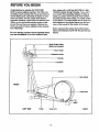
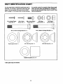
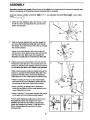
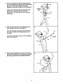
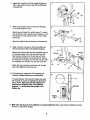
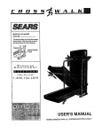
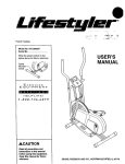
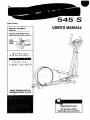
®
545
S
Patent Pending
Model No. 831.285270
Serial No.
USER'S MANUAL
Write the serial number in the
space above for future reference.
EXE_RCISE
EQUIPMENT
HELPLINEI
1-800-736-6879
SEARS, ROEBUCK AND CO.,
HOFFMAN ESTATES, IL 60179
www.proform.com
new products, prizes,
fitness tips, and much morel
545
S
TABLE OF CONTENTS
IMPORTANT PRECAUTIONS
.............................................................
BEFORE YOU BEGIN ...................................................................
PART IDENTIFICATION CHART ...........................................................
ASSEMBLY ...........................................................................
HOW TO USE THE ELLIPTICAL ...........................................................
MAINTENANCE .......................................................................
CONDITIONING GUIDELINES ............................................................
PART LIST ...........................................................................
EXPLODED DRAWING .................................................................
HOW TO ORDER REPLACEMENT PARTS ...........................................
FULL 90-DAY WARRANTY
.......................................................
2
3
4
5
6
9
11
12
14
15
Back Cover
Back Cover
3
BEFORE YOU BEGIN
Congratulations for selecting the PROFORIVP
545S low-impact elliptical exerciser. The 545S Is an
incredibly smooth exemiser that moves your feet In a
natural elliptical path, minimizing the Impact on your
knees and ankles. And the unique 545S features
adjustable resistance, upper-body and stationary handlebars, and a multi-mode exemise monitor to help
you get the most from your exercise. Welcome to a
whole new wodd of natural, eUiptical-motion exercise
from PROFORM.
tlons, please call our toll-free HELPLINE at 1-800736-6879, Monday through Saturday, 7 a.m. until 7
p.m. Central Time (excluding holidays). To help us
assist you, please note the product model number
and sedal number before calling. The model number
is 831.285270. The serial number can be found on a
decal attached to the elliptical trainer (see the front
cover of this manual for the location of the decal).
Before reading further, please look at the drawing
below and familiarize yourseff with the parts that are
labeled.
For your benefit, reed this manual carefully before
you use the elliptical. If you have additional ques-
Water Bottle Holder
(Bottle not included)
Book Holder
Resistance Knob
T-Handle
Handlebar
Upright
Side Shield
FRONT
LEFT SIDE
Pedal
Pedal Arm
4
BACK
PART IDENTIFICATION CHART
Use the chart below to identify the small parts used in
assembly. The number in parenthesis below each part
refers to the key number of the part, from the PART
LIST on page 14. The number after the dash indicates
M4 x 19mm Flange
Screw (9)---6
the quantity needed for assembly. Note: Some small
parts may have been pre-attached for shipping. If
a part Is not In the parts bag, check to see if It has
been pre-ettached.
M6 x 16mm Button
Screw (54)--4
M4 x 16mm
Screw (16).--4
M6 Nylon
Locknut (55)---2
M10 Nylon
Locknut (29)--6
M10 x 68mm Carriage Bolt (60)---2
M10 x 75mm Carriage Bolt (47)--2
m
Nylon Spacer (39)---2
3/4" Axle Cap (43)_*
Pedal Arm Spacer (41)--2*
* Extra parts may be Included.
5
5/8" Axle Cap (57)--2*
ASSEMBLY
Assembly requires two people. Place all parts of the elliptical in a cleared area and remove the packing materials. Do not dispose of the packing materials until assembly is completed.
Assembly requires a phillips screwdriver (_.=,===-,
two adjustable wrenches (_::_,
and a rubber
mallet _.
1. Attach the Rear Stabilizer (33) to the Frame (t) with
two M10 x 75mm Carriage Bolts (47) and two MIO
Nylon Locknuts (29).
2.
Hold the Console Bracket (45) near the Upright (3)
and insert the Resistance Cable (26) down through
the Upright. Feed the Extension Wire (62) up through
the Console Bracket.
52
Attach the Console Bracket (45) to the Upright (3)
with two M6 x 16mm Button Screws (54) and two M6
Split Washers (38). Make sure not to pinch the
Resistance Cable (26) or the Extension Wire (62).
.
Making sure that the Reed Switch Wire (25) and the
Resistance Cable (58) are in the indicated slot in the
Frame (1), slide the Front Stabilizer (34) into the Frame.
Do not allow the Wire or the Cable to get pinched.
54_,.-,
88
_38
26
i
3
:i
While a second person holds the Upright (3) near the
Frame (1), connect the Reed Switch Wire (25) to the
Extension Wire (62). Next, connect the Resistance
Cable (26) to the Lower Cable (58) in the following way:
i
I'
\ 29
\\\A
i
e
.
• Refer to drawing A. Pull up on the metal bracket,
and insert the tip of the Resistance Cable (26) Into
the wire clip on the Lower Cable (58) as shown.
saotf
• Refer to drawing B. Firmly pull the Resistance
Cable (26) and slide it into the metal bracket on the
Lower Cable (58) as shown.
• Refer to drawing C. Using pliers, squeeze the prongs
on the upper end of the metal bracket together.
Pull any slack Resistance Cable (26) out of the top of
the Upright (3). Attach the Upright to the Front
Stabilizer (34) with two M10 Nylon Locknuts (29).
Attach the Upright to the Frame (1) with two M10 x
68mm Carriage Bolts (60) and two MIO Nylon
Locknuts (29).
.,,,.-------54
. , _266.=
)%'>...\
c
""4
2_6
"_ Metal
! Bracket
i/_-58
6
Metall
Bracket
4.
While a second person holds the Console (6) near
the Console Bracket (45), connect the Extension Wire
(62) to the console wire. Make sure the slack
Resistance Cable (26) is pulled out of the Upright (3).
4
Attach the Console (6) to the Console Bracket (45)
with four M4 x 16mm Screws (16). Push the
Resistance Control Knob (50) onto the Resistance
Control (26).
Wire
;,;
/
16
5. Make sure that there are two Pivot Bushings (56) in
each Handlebar (8) and in the Updght (3).
Tap a 5/8" Axle Cap onto one and of the Pivot Axle
(2). Apply a thin film of the included grease to the
Pivot Axle.
57
Insert the Pivot Axle (2) through one of the Handlebars
(8) and the Upright (3).
2
56
6. Slide the other Handlebar (8) onto the Pivot Axle (2).
Secure the Handlebars to the Updght (3) by tapping a
5/8" Axle Cap (57) onto the end of the Pivot Axle.
6
3"-'---
7
7. Attach the T-handle (10) to the Updght (3) with two
M6 x t6mm Button Screws (54) and two M6 Nylon
Locknuts (55).
7
O
8. Make sure that there are four Pedal Arm Bushings
(11) in each Pedal Arm (12).
63
8
11
Identify the Left Pedal (31), which has an "L" molded
into its bottom surface. Attach the Left Pedal to one of
12
the Pedal Arms (12) using three M4 x 19mm Flange
Screws (9).
Attach the Right Pedal (not shown) in the same way.
9.
9
Apply a thin film of grease to the left Handlebar (8)
and the Crank Arm (59) in the Indicated Iocat=_ons.
Slide a Nylon Spacer (39) onto the Handlebar (8) and
a Pedal Arm Spacer (41) onto the Crank Arm (59).
Next, slide the Pedal Arm (12) with the Left Pedal
(31) onto the Handlebar and the Crank Arm. Secure
the Pedal Arm by tapping one 3/4" Axle Cap (43) onto
the Handlebar and another one onto the Crank Arm.
43
Attach the other Pedal Arm (not shown) to the right
side of the elliptical in the same way.
Grease
59
Greas
31
41
10. The Console (6) requires two =AA"battedes (not
included). Alkaline battedes are recommended.
To install battedes, first locate the battery clip under
the Console (6). Insert two battedes into the battery
clip as shown, Make sure that the batteries are
tumed so the negative ends of the batteries
(marked =-') are touching the springs in the
battery clip.
_6
10
@ I_
7Battedes
Ba.e__
Cl,p--
_
L_J
I I
11. Make sure that all parts of the elliptical are propady tightened. Place a mat under the elliptical to protect
the floor or carpet from damage.
8
HOW TO USE THE ELLIPTICAL
HOW TO EXERCISE ON THE ELLIPTICAL
HOW TO ADJUST THE RESISTANCE OF THE
PEDALS
To mount the elliptical, firmly hold the handlebars or
the T-handle and carefully step onto the pedal that is
tn the lowest position. Next, step onto the other pedal.
Push the pedals until they begin to move with a continuous motion. Note: The pedal disks can turn In
either direction; it is recommended that you turn
the pedal disks In the direction shown below;
however, to give variety to your exercise, you may
choose to turn the pedal disks in the opposite
direction.
As you exercise,
you can adjust
Resistance Knob
the resistance of
the pedals with
the resistance
knob on the
console. To
increase the
resistance,
turn the knob
clockwise; to
decrease the
resistance, turn the knob counterclockwise.
Pedal
To dismount the elliptical, allow the pedals to come to
a complete stop. CAUTION: The elliptical does not
have a freewheel; the pedals will continue to
move until the flywheel stops, When the pedals are
stationary, step off the highest pedal firsL Then, step
off the lowest pedal.
9
DESCRIPTION
HOW TO OPERATE THE CONSOLE
OF THE CONSOLE
If there is a thin sheet of clear plastic on the face of
the console, remove It.
The console is designed to help you get the most
from your workouts. As you exemise, you can watch
your progress around the LED track, while the
display provides continuous exemise feedback.
The six modes of the display are described below.
1. To turn on the power, press the on/reset button or
simply begin exercising. When the power is tumed
on, one LED indicator will light in the LED track,
and the entire display will appear for two seconds.
The console will then be ready for operation.
000®000
2. Select one of the five modes:
P.A.CF.R.-
Scan mode-.__-AN OIL
LAPS
When the power
is tumed on, the
scan mode will
automatically be
SP_
TIMe BIEZ
selected. One
Mode Indicators
mode indicator
will show that the
scan mode is selected, and a flashing mode Indicator will show which mode is currently displayed.
Note: If a different mode is selected, you can
select the scan mode again by repeatedly pressing
the mode button.
000_000
LEDTreck
5CAN
CAI,.
i_
S_GD
_ME
Dl_-r.
MODE
ON/RESe'T
Speed--This mode displays your current exemise
speed, in miles per hour.
Speed, time,
/
SCAN
__..AI LAPS
,_
distance, laps,
or calode mode-I L.3
To select one of
_,PEffD
TIME DIS'E
these modes for
continuous
display, press the
mode button repeatedly. The mode indicators will
show which mode is selected. (Make sure that the
scan mode is not selected.)
I ,ol
Time--This mode displays the length of time you
have exercised. Note: If you stop exemising, the time
mode will pause until you resume.
Distance--This mode displays the total distance you
have completed, in miles.
Laps--This mode displays the number of 1/4-mile
laps you have completed around the LED track.
3. The LED track represents a distance of 114 mile. As
you exercise, the Indicators around the track will
light one at a time until you have completed 114
mile. A new lap will then begin.
Calorie---This mode displays the approximate number
of Calodes you have burned.
Scan--This mode displays the speed, time, distance,
laps, and calode modes, for 5 seconds each, in a
repeating cycle.
4. To reset the display, press the on/reset button.
5. To tum off the power, simply wait for about four
minutes. Note: The console has an "auto-off"
feature, ff the pedals are not moved and the
console buttons are not pressed for four
minutes, the power will turn off automatically
in order to conserve the batteries.
BATTERY INSTALLATION
Before the console can be operated, two "AA" batteries must be Installed. If you have not installed batteries, see assembly step 10 on page 8.
10
MAINTENANCE
CONSOLE TROUBLE-SHOOTING
Inspect and tighten all parts of the elliptical
regularly. Replace any wom parts immediately.
If the console does not function propedy, the batteries
should be replaced. To replace the batteries, refer to
assembly step 10 on page 8.
The elliptical can be wiped clean with a soft cloth and
mild detergent. Do not use abrasives or solvents.
To prevent damage to the console, keep liquids away
from the console. Use only a sealable water bottle in
the console.
STORAGE
When stodng the elliptical, remove the battedes from
the console. Keep the elliptical In a clean, dry location, away from moisture and dust.
11
CONDITIONING GUIDELINES
The following guidelines will help you to plan your
exercise program. Remember that proper nutrition
and adequate rest are essential for successful results.
gy. Only after the first few minutes of exercise does
your body begin to use stored fatcalodes for energy.
If your goal is to bum fat, adjust the intensity of your
exercise until your heart rate Is near the smallest
number in your training zone as you exemise.
For maximum fat burning, adjust the intensity of your
exercise until your heart rate is near the middle number In your training zone as you exemise.
Aerobic Exercise
If your goal is to strengthen your cardiovascular system, your exemise must be =aerobic." Aerobic exercise Is activity that requires large amounts of oxygen
for prolonged pedods of time. This increases the
demand on the heart to pump blond to the muscles,
and on the lungs to oxygenate the blood. For aerobic
exercise, adjust the Intensity of your exercise until
your heart rate is near the largest number in your
training zone.
EXERCISE INTENSITY
Whether your goal is to burn fat or to strengthen your
cardiovascular system, the key to achieving the
desired results is to exercise with the proper intensity.
The proper intensity level can be found by using your
heart rate as a guide. The chart below shows recommended heart rates for fat burning, maximum fat
buming, and cardiovascular (aerobic) exemise.
HOW TO MEASURE YOUR HEART RATE
To measure your
heart rate, first
exemise for at
least four minutes.
Then, stop exercising and place two
fingers on your
wdst as shown.
Take a six-second
heartbeat count, and multiply the result by 10 to find
your heart rate. For example, if your six-second headbeat count is 14, your heart rate is 140 beats per
minute. (A six-second count is used because your
heart rate will drop rapidly when you stop exercising.)
HEART RATE TRAINING ZONES
To find the proper heart rate for you, first find your age
at the bottom of the chart (ages are rounded off to the
nearest ten years). Next, find the three numbers
above your age. The three numbers are your "training
zone." The smallest number is the recommended
heart rate for fat burning; the middle number is the
heart rate for maximum fat burning; the largest
number is the heart rate for aerobic exemise.
WORKOUT GUIDELINES
Each workout should include the following three
important pads:
A warm-up, consisting of 5 to 10 minutes of stretching and light exercise. (See page 13.) A proper warmup increases your body temperature, heart rate, and
cimulation in preparation for exercise.
Burning Fat
To bum fat effectively,you must exemise at a relatively low intensity level for a sustained period of time.
Dudng the first few minutes of exemise, your body
uses easily accessible carbohydrate calodes for ener-
12
EXERCISE FREQUENCY
Training zone exercise, consisting of 20 to 30
minutes of exercising with your heart rate in your
training zone. (Dudng the first few weeks of your
exercise program, do not keep your heart rate in
your training zone for longer than 20 minutes.)
To maintain or Improve your condition, plan three workouts each weak, with at least one day of rest between
workouts. After a few months of regular exemise, you
may plan up to five workouts each week, if desired.
CAUTION: Be sure to progress st your own pace
and avoid overdoing it. Incorrect or excessive
training may result In Injury to your health.
Remember, the key to success is make exercise a
regular and enjoyable part of your everyday life.
A cool-down, with 5 to 10 minutes of stretching.
This will increase the flexibility of your muscles
and will help to prevent post-exemise problems.
SUGGESTED STRETCHES
The correct form for several basic stretches is shown at the
right. Move slowly as you stretch_never bounce.
1. Toe Touch Stretch
Stand with your knees bent slightly and slowly bend forward
from your hips. Allow your back and shoulders to relax as you
reach down toward your toes as far as possible. Hold for 15
counts, then relax. Repeat 3 times. Stretches: Hamstdngs,
back of knees, and back.
2. Hamstring Stretch
Sit with one leg extended. Bring the sole of the opposite foot
toward you and rest it against the inner thigh of your extended
leg. Reach toward your toes as far as possible. Hold for 15
counts, then relax. Repeat 3 times for each leg. Stretches:
Hamstdngs, lower back, and groin.
3. Calf/Achllles Stretch
With one leg in front of the other, reach forward and place
your hands against a wall. Keep your back leg straight and
your back foot fiat on the floor. Bend your front leg, lean forward and move your hips toward the wall. Hold for 15 counts,
then relax. Repeat 3 times for each leg. To cause further
stretching of the achilles tendons, bend your back leg as well.
Stretches: Calves, achilles tendons, and ankles.
4. Qusddceps Stretoh
With one hand against a wall for balance, reach back and
grasp one foot with your other hand. Bdng your heel as close
to your buttocks as possible. Hold for 15 counts, then relax.
Repeat 3 times for each leg. Stretches: Quaddceps and hip
muscles.
13
3
PART LISTmModel No. 831.285270
Key
No.
Qty.
1
2
3
4
5
6
7
8
9
10
11
12
13
14
15
16
17
1
1
1
1
1
1
2
2
6
1
8
2
10
1
1
11
2
18
19
20
21
22
23
24
25
26
27
28
29
30
31
32
33
34
35
R06OlA
Key
No.
Qty.
Frame
Pivot Axle
Upright
Right Side Shield
Left Side Shield
Console
Foam Handlebar Grip
Handlebar
M4 x 19mm Flange Screw
T-handle
Pedal Arm Bushing
Pedal Arm
M5 x 16mm Button Screw
Resistance Strap
Strap Buckle
M4 x 16mm Screw
M6 Nut
36
37
38
39
40
41
42
43
44
45
46
47
48
49
50
51
52
2
2
2
2
1
2*
1
4*
1
1
2
2
1
1
1
4
1
Pulley Beadng
Pedal Disk
M6 Split Washer
Nylon Spacer
Side Shield Bracket
Pedal Arm Spacer
Right Pedal
3/4" Axle Cap
M4 x 16mm Fiat Screw
Console Bracket
Front Stabilizer Endcep
M10 x 75mm Carriage Bolt
Cable Clamp Assembly
M4 x 64mm Button Screw
Resistance Control Knob
M5 x 28ram Button Screw
Return Spring
2
2
2
1
2
1
1
1
1
2
1
6
1
1
Adjustment Bracket
Eyebolt
M8 Nylon Jam Nut
Flywheel Axle
Flywheel Bearing
Flywheel
Magnet
Reed Switch/Wire
Resistance Control/Cable
Rear Stabilizer Endcap
Tension Spdng
M10 Nylon Locknut
Belt
Left Pedal
53
54
55
56
57
58
59
60
61
62
63
64
65
#
2
4
2
6
2*
1
2
2
1
1
2
1
1
1
8,5 Washer
M6 x 16ram Button Screw
M6 Nylon Locknut
Pivot Bushing
5/8" Axle Cap
Lower Cable
Crank Arm
M10 x 68mm Cardage Bolt
Reed Switch Clamp
Extension Wire
T-handle Endcap
Plastic Washer
Crank Arm Plastic Spacer
Grease Packet
1
1
1
2
Pulley w/Shaft
Rear Stabilizer
Front Stabilizer
5116"Zinc Bolt
#
#
#
#
1
2
1
1
User's Manual
Side Shield Decal
Warning Decal
Hardware Kit
Description
Description
Note: "#" indicates a non-illustrated part. "," indicates that an extra part may be included. Specifications are
subject to change without notice. See the back cover of this manual for information about ordedng replacement
parts.
14
9
12
>
SEARS
The model number and sedal number of your PROFORIVP 545S
are listed on a decal attached to the frame. See the front cover of
this manual to find the location of the decal.
Model No. 831.285270
All replacement parts are available for immediate purchase or
special order when you visit your nearest SEARS Service Center.
To request service or to order parts by telephone, call the toll-free
numbers listed at the left.
QUESTIONS?
If you find that:
• you need help assembling or
operating the PROFORM e 545S
When requesting help or service, or ordering parts, please be prepared to provide the following Information:
• a part is missing
• or you need to schedule repair
service
• The MODEL NUMBER of the product (831,285270)
• The NAME of the product (PROFORM e 545S elliptical)
call our toll-h_e HELPMNE
• The SERIAL NUMBER of the product (see the front cover of this
manual)
1-800-736-6879
Monday-Saturday, 7 am-7 pm
Central Time (excluding holidays)
• The KEY NUMBER and DESCRIPTION of the part(s) from page
14 of this manual.
REPLACEMENT
PARTS
If parts become worn and need to
be replaced, call the following
toll-free number
1-800-FON-PART
(1-800-366-7278)
I
FULL 90 DAY WARRANTY
I
For 90 days from the date of purchase, if failure occurs due to defect in material or workmanship in this
SEARS ELLIPTICAL EXERCISER, contact the nearest SEARS Service Center throughout the United
States and SEARS will repair or replace the ELLIPTICAL EXERCISER, free of charge.
This warranty does not apply when the ELLIPTICAL EXERCISER is used commemially or for rental
purposes.
This warranty gives you specific legal rights, and you may also have other rights which vary from state
to state.
SEARS, ROEBUCK AND CO., DEPT. 817WA, HOFFMAN ESTATES, IL 60179
Part No. 175921 R0601A
Pdnted in China © 2001 Sears, Roebuck and Co.