1
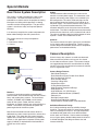
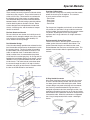
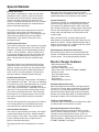
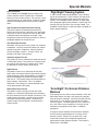
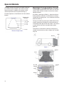
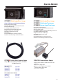
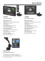
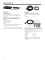
Special Markets Special Markets Rear Vision System Description The system is a solid state electronic video surveillance system. The video surveillance system is intended for on-vehicle use for the purpose of viewing blind spots and aiding vehicle operators in viewing around the vehicle during operation. The goal of this system is to enhance safety and improve operator efficiency. Is is necessary to explain the system components for better understanding of how the system works. The system consists of 3 major components: 1. Monitor 2. Interconnect Cable 3. Camera Cameras The camera contains the optics (glass lens) and electronics for viewing and image processing. There are many camera design considerations which result in exceptional performance and extended reliability. Monitor Camera Description Interconnect Cable Camera Multimedia Control Station Camera Power Supply Interconnect Cable Camera Monitors A variety of stand alone monitors and multimedia control stations are manufactured for use with Clarion’s heavy and medium duty cameras. The stand alone monitors (CJ7000E and CJ56000) are the control center for the system. Power, dimmer, contrast, brightness, and other functions are accessed from the monitor. The monitor also provides the power and power regulation for the entire system. Most Clarion multimedia control stations feature a dedicated rear vision camera input with a reverse wire trigger input. This allows the rear camera image to appear on the screen when the vehicle is placed into reverse. In this application a separate Clarion power supply (CAA185) is required when interfaced with a Clarion rear vision camera. 162 Cables The interconnect cables connects the camera to the monitor or camera power supply. The connection at the monitor and camera power supply are a standard 5-pin DIN configuration. The cable’s male end plugs into the female socket located on the back of the monitor or on the power supply. The camera connects to the cable via a patented O-ring sealed threaded connector. This connector effectively seals the system from the outside environment. The cable is designed and manufactured to withstand harsh chemicals such as hydraulic fluid and oil. The cable is shielded to offer the highest degree of noise rejection. Cables are available from 23’-65’. Clarion’s heavy duty systems are solid state electronic video surveillance cameras and are part of a closed circuit video surveillance system. The cameras incorporate rugged design features that enable them to reliably function in the harsh environment of commercial vehicles, such as large diesel trucks. Camera Design Features - Solid State Electronics - Dual-Sided Glass Epoxy Printed Circuit Board - Die Cast Aluminum Chassis - Dual Chamber Design - Precision O-Ring Seals - Sealed Front Glass - O-Ring Sealed Connector - Wide Operation Temperature Range - Wide Angle Lens - High Resolution 1/4” CCD Element - Automatic Motorized Shutter (CC2001E) - Electronic Iris - Backlight Compensation - Stainless Steel Mounting Hardware - Environmentally Tested to SAE-J1455 Standards Solid State Electronic Design An all solid state design ensures reliability through simplicity. The use of multiple IC’s leaves fewer components in the design that may fail. All large components are soldered and glued to the circuit board to better resists shock and vibration. Surface mount technology on an all glass epoxy, double-sided printed circuit board is utilized throughout the design to reduce size and increase reliability. Special Markets Small Printed Circuit Board Design There are only two small printed circuit boards inside of the heavy duty cameras. They are the frame for all of the main circuitry. These boards are anchored to the inside chassis of the camera at multiple points. This two board design minimizes wired connections between boards, thus eliminating a potential problem of wires breaking due to vibration or shock. Some camera designes use multiple boards inside of the chassis, increasing size, and the number of components that could fail. Die Cast Aluminum Chassis Die cast aluminum was chosen for its ability to resist corrosion and its strength to weight ratio. Using a die cast aluminum chassis offers great durability in a small, weather resistant package. Dual Chamber Design A dual chamber design provides two moisture barriers from the outside environment to the electronics inside the camera chassis. The first chamber is formed by the lead holder and small printed circuit board. The cable, or extension lead, is connected to the lead holder, and the wires are connected to the printed circuit board via a molex type plug. An O-ring seal fits between the lead holder and the main chassis, and an additional O-ring is placed between the PCB and the inside chassis. If for some reason, water does enter the camera through the cable, it will stop in the first chamber and never get into the main chamber where the lens and CCD electronics are housed. Precision O-Ring Seals Four precision O-ring seals are used to seal the camera where the chassis parts fit together. The camera’s chassis consists of four main parts. - Front Cover - Rear Cover - Lead Cover - Front Plate For the parts to fit together and maintain an environmentally sound seal, precision O-rings made from corrosion resistant rubber are used where the front and rear covers are joined. Screwing the chassis’ parts together compress the O-rings and forms an airtight and watertight seal. Environmentally Sealed Front Glass Like the main chassis, the front glass is sealed with a rubber gasket that wont corrode or break down. The gasket surrounds the glass and both are then sandwiched between the front cover and the front plate. This method of construction offers the greatest resistance to leakage. Gasket Glass (Inserted in gasket) Gasket Seat Front Plate O-Ring Plate Extension Lead Lead Holder O-Ring Seal Rear Cover O-Ring Seal O-Ring Sealed Connector Many steps have been taken to ensure that the camera chassis is environmentally sealed, and the same care has been given to the cable entering the cable. Some camera designs are prone to leakage at the connector, but Clarion’s patented threaded O-ring connector is designed to prevent water from entering the cable. Our proprietary connection system has an O-ring seal inside the connector on the extension lead which mates with the interconnect cable. When the connectors are tightened the O-ring is compressed, which creates a watertight barrier. Front Cover Threaded Lug O-ring Seal Threaded Sleeve 163 Special Markets Glass Lens The shape of the lens determines the focus and view angle of the camera. Our glass lens offers many advantages over the plastic lenses used by other manufacturers. Glass is much harder and can be more accurately shaped than plastic. Temperature extremes will alter a plastic lenses shape, causing distortion. Glass will not change its shape through temperature extremes, and will not become discolored due to UV rays. a shadow being cast by the vehicle, or backing into a covered bay on a sunny day). Manually controlled from the monitor, this feature can be turned on or off at any time, improving low light viewing. Wide Operational Temperature Range The exceptional build quality and design allows our cameras to operate over a wide range of temperature extremes. Even a temperature shock, like going from a warm parking bay to the cold outside, will not hinder the camera’s operation. The camera will operate in temperatures below -22F (-30C) and above +158F (+70C) degrees. Environmentally Tested to Strict Standards (SAE J1455) Wide Angle Lens Clarion’s wide angle lens (118 degrees Horizontal X 89 degrees Vertical) has been optimized to introduce the least amount of distortion while offering the greatest view area. High Resolution 1/4” CCD Element Clarion uses a 250,000 pixel CCD. The more pixels, the sharper and clearer the picture will be. The small 1/4” CCD chip also allows for a compact camera design. The industry standard is 180,000 to 250,000 pixels. Automatic Motorized Shutter The CC2001E camera has a motorized lens cover or shutter, which opens when the camera is on and closes when the camera is off. The shutter keeps dirt, water, snow, and dust off of the lens when the camera is not in use. Our shutter is protected by a special clutch mechanism that allows the shutter to “slip” if obstructed from moving or forced open or closed. This design is tested over one million cycles and is patented by Clarion Company LTD., Tokyo, Japan. Electronic Iris (DSP) Digital Signal Processing (DSP) is used to simulate a mechanical iris. A microprocessor modulates the CCD signal on and off, simulating the opening and closing of a mechanical iris. Our advanced electronic iris eliminates unnecessary mechanical parts, and offers increased performance and reliability. Backlight Compensation Circuit Another advantage of using DSP, which is utilized in many professional video surveillance systems, is its ability to eliminate silhouettes that may occur when there are large contrasts in the viewing area (like a 164 Stainless Steel Mounting Hardware All mounting hardware - screws, washers, bolts, and the mounting brackets are made of stainless steel. We chose stainless steel because of its durability, ensuring a secure installation. The CC2001E, CC2000E, CC2003E, and CC2002E have been independently tested to SAE J1455 design recommendations. The following tests were performed: - Temperature cycling resistance - Thermal shock resistance - Humidity resistance - Salt/Fog resistance - Splash resistance - Water jet resistance - Sand and dust resistance - Altitude resistance - Operational shock resistance - Operational vibration resistance - Leakage resistance - Fluid damage resistance - Icing damage resistance - Solar radiation resistance - Fungus resistance - EMI testing Environmental Test Procedure The tests performed on these products were developed to be in accordance with SAE J1455 Recommended Design and Engineering Practices, which set standards required by truck manufacturers. Many SAE J1455 standards exceed MIL SPEC testing requirements. Temperature Cycling Resistance The temperature is slowly raised and lowered from -40F (-40C) to +185F (+85C) multiple times, over a 48 hour period. The camera is then turned on and tested. No operational or physical anomalies were found. This test subjects the entire camera and its internal components to thermal expansion and contraction. Theoretically, any flaws in solder joints, the rigid PCB, or aluminum housing would be exposed by continual thermal cycling. Special Markets Thermal Shock Resistance The camera is placed in a test chamber conditioned at -40F (-40C) for three hours. After 3 hour soak, the temperature is raised to +185F (+85C) in a period of 1 minute. The temperature is maintained there for 2 hours then dropped again to -40F (-40C). This cycle is performed 5 times. No operational or physical anomalies were found. Like the temperature cycling test, this test is intended to expose any problems with the solder joints, rigid PCB, and/or the aluminum housing. Humidity Resistance The camera is put into a chamber set at +185F (+85C), relative humidity set at 95%. The camera is then soaked for 2 hours at the setting. Next, the temperature is dropped to -40F (-40C) and left there for 2 hours. The chamber temperature is then increased to +100F (+38C) relative humidity 95% within 1 hour and left to soak for 1 hour. Temperature is then increased to +180F (+82C) within a 30 minute period. This process is repeated 5 times. The camera is then left to return to ambient conditions. No operational or physical anomalies were found. The purpose if this test is to cause thermal expansion and contraction of the air inside of the camera. If the camera chassis is air and water tight, no moisture will enter the camera during thermal contraction immediately following the thermal expansion. Salt Fog Resistance The camera is placed in a test chamber. A salt spray mixture consisting of de-ionized water and sodium chloride is atomized through specially designed nozzles and sprayed on the camera and in the chamber. The air is maintained at 85% relative humidity at the point of release at the nozzle. The salt solution is maintained at a temperature of +95F (+35C). The test is conducted for 48 hours. Then the camera is left to dry at ambient temperature. No operational or physical anomalies were found. This test shows that the corrosive nature of the sodium chloride and water had no effect on the camera chassis and cable connection. Splash Resistance This test is conducted in a sealed chamber. The camera is subjected to a solid cone spray 0.25cm in diameter delivered at a 45 degree angle below and above the camera for a period of five minutes. Upon completion of the water test, the same spray test is done with MIL-H-5606 Hyraulic Fluid for five minutes. No operational or physical anomalies were found. The purpose of this test is to be sure that the camera has no micro leaks smaller than H20 molecules. Hydraulic fluid molecules are smaller than H20 molecules. Water Jet Resistance The camera is placed on a test fixture with a nozzle placed directly in front of the chassis. The nozzle is aimed for 100% coverage of the front surface of the camera. The water temperature is adjusted to +199F (+93C) and an impact pressure of 31.0 kPa minimum. The spray is controlled at 375 cycles at a rate of 3 seconds out of every 6 seconds for a total of 37.5 minutes. No operational or physical anomalies were found. This test shows if there will be any damage to the camera by the use of high pressure water hoses or wands. Sand and Dust Resistance The camera is placed in the center of the test chamber. An environment of +73F (+23C) is maintained with a relative humidity of no less than 22%. An air velocity of 1750 feet per minute (FPM) stirs up a dust concentration of 0.3 grams per cubic foot. The airstream is directed at the most vulnerable areas of the camera. This is maintained for a period of 6 hours at which point the temperature is increased to +145F (+63C) and air reduced to 300 FPM. These conditions are maintained for 16 hours. The chamber is then returned to the first test parameters of 1750 FPM and +73F (+23C). This is maintained for another 6 hours. No operational or physical anomalies were found. The purpose of this test is to determine any adverse effects of dust and “sandblasting” type of punishment. This test approximates the normal wear due to dust and dirt that a camera will go through in a 5 year period of operation on a vehicle. Altitude Resistance This test simulates high altitude for 48 hours while cycling temperature from -40F (-40C) to +185F (+85C). No operational or physical anomalies were found. The purpose of this test is to ensure that pressure differences of the internal chassis to the external would not cause a leak in the seals of the main chassis. Operational Shock Resistance The camera is rigidly mounted to a test fixture. The fixture is then mounted to a test shaker. The camera is tested through the entire procedure while it is ‘on’. A 30G (G-Force) shock is applied to the camera 3 consecutive times. No operational or physical anomalies were found. 165 Special Markets Leakage Resistance The camera is immersed in a water tank with water controlled at +64F (+18C) for a total of 15 minutes. During the test cycle, the camera is rotated around every five minutes. After the 15 minute cycle, the camera is removed and cooled to +23F (-5C) and then returned to ambient temperature. No operational or physical anomalies were found. The purpose of this test is to determine if water will leak into the camera when fully submerged and subjected to cool temperatures. The final cooling and return to normal temperature cycle will produce condensation in the interior of the camera if any leakage occurred. Fluid Damage Resistance The camera is placed into a test chamber and sprayed with water over a 24 hour period. The camera is then placed in a chamber with a controlled temperature of +160F (+71C) for 48 hours. After this 48 hour soak, the camera is placed back in the spray chamber and subjected MIL-H-5606 Hydraulic Fluid Spray for 24 hours. No operational or physical anomalies were found. The purpose of this test is to determine if long term exposure to fluid will cause the seals to break down and leak. Water was used at first, then hydraulic fluid. Because hydraulic fluid has smaller molecules than water, and has a corrosive property, it makes for an ideal test medium in determining micro-leakage. Icing Damage Resistance The camera is placed in a test chamber. The temperature is lowered to +32F (0C). The camera is subjected to a uniform rain spray of precooled water for a period of one hour. The temperature is adjusted down to +14F (-10C) and the camera is subjected to rain spray until 0.25” of ice accumulates on the outside surface. This state is maintained for 6 hours. With the exception of the 0.25” of ice preventing the camera shutter from moving no operational or physical anomalies were found. This test will help determine if the glass lens will break or if any components on the outside of the camera react adversely to or become brittle due to the ice. Solar Radiation Resistance The camera is placed inside a test fixture. Solar lights are placed 30” above the camera. Ambient temperature is raised to +120 (+49C). The camera is exposed to solar radiation for 48 hours. No operational or physical anomalies were found. The purpose of this test is to determine if any break166 down will occur to the camera’s exterior or interior components that are exposed to solar radiation. This test approximates 30 days of continuous solar radiation. Fungus Resistance The camera is placed in a controlled environment and mixture of fungus spores are sprayed on the camera. The samples are allowed to grow at +86F (+30C) with 90% relative humidity over a 28 day period. At the end of the test, with the exception of a light build-up of fungus on the cable and lead holder, no fungus grew on the camera’s body. SAE J145 requires that a fungus build-up test be performed on all components that will be placed on the exterior of a vehicle. If fungus would have been able to build-up on the camera lens, it would render the system useless until the fungus is removed. Electromagnetic Interference Resistance Because the camera alone can not be tested for EMI rejection, the EMI testing was performed on the entire camera system. The system passed the EMI test. Monitor Design Features - Solid state electronic design - 12V or 24V operation - Backlight compensation circuit - Built-in two camera switch (CJ7000E, CJ5600E) - Anti-glare screen - User adjustable controls - Automatic system turn-on - Night dimmer - Removable power harness Solid State Electronic Design Solid state design ensures reliability through simplicity. The use of IC’s leaves fewer components in the design that may fail. All large components are soldered and glued to the board to better resist shock and vibration. Surface mount technology (SMT) is utilized throughout the design to reduce size and increase reliability. 12 Volt or 24 Volt Operation The power supply in the monitor will automatically adjust for vehicles with a 24 volt electrical system Backlight Compensation Circuit (BLC) The monitor has built-in circuitry that sends a turn-on signal to the BLC equipped cameras. This signal either activates or deactivates the BLC feature. BLC is an excellent way of controlling the picture quality in nearly all lighting conditions. Monitors with this feature are: CJ7000E, CJ5600E, and CJ981E Special Markets Camera Switcher The CJ7000E and CJ56000E feature a built-in two camera switcher and the CJ981E with a EA1246A features a three camera switcher. The cameras can be activated manually or automatically. Automatic triggers requires interfacing with the reverse and turn signal wires. High Temperature Impact Resistant Housing The plastic used for the outside of the monitor is impact resistant to ensure a long life in any application. The plastic is also UV resistant so it will not dull, fade, or become brittle from exposure to sunlight. High temperature plastic will not warp or bend as a result of prolonged exposure to sunlight or heat. ‘RightSight’ Viewing System In 1997 Clarion introduced ‘RightSight” camera technology to the market place. These cameras are specifically designed and manufactured for viewing the side of the vehicle. The CC2002E camera features a narrow angle lens (40 degree angle) which provides a ’tighter shot’ and ensures that only the critical area is being viewed. The CC2002E makes objects in view look larger, and depth of field is greatly improved. User Adjustable Controls All buttons are large and clearly marked. For simplicity of operation, a minimal amount of buttons are used to control all functions. Brightness, Contrast, Markers, On/Off, Day/Night, Camera 1, Camera 2, BLC, are located on the front of the monitors. Automatic System Turn-On The system will turn on automatically when the vehicle is shifted into reverse. The system can also be turned on manually with the push of a button, which allows the operator to use the system while driving. Night Dimmer The power harness has a connection for the dash lights, which will automatically dim the monitor (reduce screen brightness) when the headlights are turned on. When the headlights are turned on, the dash lights also turn on. The monitor senses the voltage from the lights and dims automatically. This is an optional connection. The monitor can also be dimmed manually by pressing the “DIM” button. Removable Power Harness The power harness that plugs into the rear of the monitor has a removable connection which provides a for quick-disconnect from the vehicle if necessary. The modular plugs also allows a vehicle to be pre wired during the manufacturing process. Installation of a camera system after the vehicle is manufactured is simple and fast. (View Extends Further Than Shown) ‘RightSight’ Camera Field of View ‘AccuSight’ On-Screen Distance Markers Even though the rear vision camera provides a clear view behind the vehicle, the view is not necessarily representative of distance and depth. Much like the right side rear view mirror on a car, objects in the monitor are closer than they appear. The wide angle lens that is necessary for a rear vision camera introduces a “fish-eye” type of distortion causing objects to be seen in a different perspective. In the past Clarion and other manufacturers have dealt with this reality by printing dots on an overlay on the monitor’s screen. Clarion has now taken this a step further with monitors that incorporate electronically generated on-screen distance markers. This feature is referred to as “AccuSight”. 167 Special Markets ‘AccuSight’ markers help the driver judge the distance to an obstacle when needed, and can be turned off when not wanted. In addition, the markers can be used to help the driver line-up when backing up. Each dot represents a fixed distance from the vehicle’s bumper. Vehicle Width MARKER FIELD DISTANCE 23’ (7M) 16.45’ (5M) 9.8’ (3M) 3.3’ (1M) Bumper Distance Gauge Values Backlight Compensation Circuit The Backlight Compensation Circuit (BLC) can improve viewing under extreme variations in contrast or in poor lighting situations. As showin in the diagram (DIAG. 1), when the vehicle is backing toward an obstacle, and the vehicle is casting a shadow into the viewing area, it can be difficult to see the obstacles (DIAG. 2) Turning on the BLC by pressing the “IRIS” button on the monitor improves this condition by limiting the contrast and allowing more light to enter the camera. The result is a much clearer view of the area behind the vehicle (DIAG. 3). This feature is useful when a vehicle is backing into a shaded maintenance bay, under a bridge, into a shaded alley, etc. Wall Shadow DIAG. 1 Cones Shadow Cones DIAG. 2 Shadow BLC ON Indicator Cones IRIS Bumper DIAG. 3 168 Special Markets CC2001E Wide Angle/Mirror Image Color CCD Camera with Motorized Shutter Heavy Duty Camera Design Die-Cast Aluminum Chassis Dual Chamber Design 118 Degree Wide Angle View Lens Automatic Motorized Shutter with Clutch High Resolution 1/4” CCD Imager Backlight Compensation Circuit Electronic Iris Patented Waterproof Connection System Stainless Steel Mounting Hardware Included Weather-Resistant CC200XE Heavy Duty Camera Cables Compatible with: CC2001E, CC2000E, CC2003E, CC2002E cameras Camera Cables: (5M/16FT) (10M/33FT) (15M/49FT) (20M/65FT) CCA-416 CCA-393 CCA-394 CCA-395 CC2000E Wide Angle/Mirror Image CC2003E Wide Angle/True Image CC2002E Narrow Angle/True Image Heavy Duty Camera Design Die-Cast Aluminum Chassis Dual Chamber Design CC2000E/CC2003E: 118 Degree Wide Angle View Lens CC2002E: 40 Degree Angle View High Resolution 1/4” CCD Imager Backlight Compensation Circuit Electronic Iris Patented Waterproof Connection System Stainless Steel Mounting Hardware Included Weather-Resistant CAA-185 Camera Power Supply Camera power supply for medium and heavy duty cameras Reverse wire trigger input Full time camera trigger switch included Composite (RCA) video output 12v and 24v compatible Camera Extension Cables: (0.9M/3FT) CCA-439 (5M/16FT) CCA-391 (10M/33FT) CCA-415 169 Special Markets CJ981E EA1232A 112,230 Built-in Camera Power Supply Pixel Resolution Brightness, and Contrast Control Camera Selection, ZOOM, IRS, ON/OFF Front Panel Control Auto Day/Night Dimming Electronic Distance Markers 12v and 24v Compatible Monitor Mounting Bracket Included Color, RCB174 Included Single Camera Power Supply for CJ981E Camera Power Supply for Medium and Heavy Duty Cameras. Reverse Wire Trigger Input Composite (RCA) Auxiliary Video Input Composite (RCA) Video Output Digital Zoom/Auto Iris Control Wired Remote Control Included (RCB174) with Zoom and Iris Select Buttons 12v and 24v Compatible Requires External Power Supply Box RCB174 Optional EA1246A Multiple Camera Power Supply for CJ981E Built-in Camera Power Supply for Medium and Heavy Duty Cameras. Turn Signal and Reverse Wire Trigger Inputs Composite (RCA) Auxiliary Video Input Composite (RCA) Video Output Digital Zoom/Auto Iris Control Wired Remote Control Optional (RCB174) with Zoom and Iris Select Buttons 12v and 24v Compatible 170 Special Markets CC3000E Wide Angle/Mirror Image Color Camera with IR Illuminators and Built-in Microphone Medium Duty Camera Design Die-Cast Aluminum Chassis 90 Degree Wide Angle View Lens IR Illuminators 0.06 Lux Sensitivity High Resolution 1/3” Imager Backlight Compensation Circuit Built-in Microphone Patented Waterproof Connection System Stainless Steel Mounting Hardware Included Weather-Resistant CC3000E Medium Duty Camera Cables Camera Cable for CJ7000E or CJ5600E Monitors (20M/65FT) CCA-729 Camera Cable for CJ981E Monitors (20M/65FT) CCA-728 CCA-730 Universal Power, Audio/Video Pigtail Adapter for CCA-729 Adaptor CCA-730 (DIN Connector to RCA and Power Connectors: Allows the CC3000E to be interfaced with any monitor with a composite RCA video and audio input) 171 Special Markets CC2015E CC2011E / CC2012E CC2011E CC2015E CC2012E Medium Color Camera Wide Angle / Mirror Image Color Camera Wide Angle / True Image Medium Duty Camera Weather-Resistant Die Cast Aluminum Chassis High Resolution 1/4” Imager 130 Degree Wide Angle View Backlight Compensation Circuit Patented Waterproof Connection System Mounting Hardware Included Compact Color Camera with Stainless Steel Cover Wide Angle / Mirror Image Duty Camera Weather-Resistant Die Cast Aluminum Chassis High Resolution 1/4” Imager 130 Degree Wide Angle View Backlight Compensation Circuit Patented Waterproof Connection System Mounting Hardware Included Compact CC201XE Medium Duty Camera Cables Compatible with: CC2011E, CC2012E, CC2015E cameras CAA-185 Camera Power Supply Camera Cables: (7M/23FT) (10M/33FT) (15M/49FT) (20M/65FT) MF23RM CCA-533 CCA-534 CCA-535 Camera power supply for medium and heavy duty cameras Reverse wire trigger input Full time camera trigger switch included Composite (RCA) video output 12v and 24v compatible camera not included PQE033 Camera Cover Compatible with: CC2011E, CC2012E, CC2015E cameras Molded Can 172 plastic cover for a “finished look” on the vehicle. be painted to match the vehicle’s exterior color. Special Markets CJ7000E CJ5600E 7-inch LCD Color Monitor 5.6-inch LCD Color Monitor Medium Medium 336,960 224,6400 Duty Color Monitor Pixel Resolution Built-in Camera Power Supply for Medium and Heavy Duty Cameras Built-in Two Camera Switcher LED Backlighting Color, Brightness, and Contrast Controls Auto Day / Night Dimming True or Reverse Image Switching Function Reverse Wire Trigger Input Turn Signal Wire Trigger Input Composite (RCA) Video and Mono Audio Input Built-in Speaker Seven Different On-Screen Languages NTSC/PAL Compatible 12v and 24v Compatible Monitor Mounting Bracket Included IR Remote Control Included Duty Color Monitor Pixel Resolution Built-in Camera Power Supply for Medium and Heavy Duty Cameras Built-in Two Camera Switcher LED Backlighting Color, Brightness, and Contrast Controls Auto Day / Night Dimming True or Reverse Image Switching Function Reverse Wire Trigger Input Turn Signal Wire Trigger Input Built-in Speaker Seven Different On-Screen Languages NTSC/PAL Compatible 12v and 24v Compatible Monitor Mounting Bracket Included monitor not included LAA-057-100 Rear View Mirror Monitor Mount The mount replaces the rear view mirror providing a mounting base for a LCD monitor with a slide mount base. Mount has provisions for up, down, left, and right adjustments for increased driver visibility. 173 Special Markets RCA-223 3 Camera Switch Three cameras can be connected to a single monitor be interfaced with a combination of medium and heavy duty cameras. Desired camera image can be selected by pressing the applicable camera selecton button ‘Manual Mode’. Each camera can be switched automatically when set in ‘Auto Mode’. Reverse wire trigger input (2) Trigger wire inputs 12v and 24v compatible Can CCA-454 Truck Cab to “Break Point” Cable Connection cable between the monitor and the “Break Point” (15M/49FT) CCA-454 NOTE: Can be interfaced directly to Clarion ‘Surround Sight’ Monitors: CJ7000E, CJ5600E, and CJ981 monitor system Can be interfaced with any monitor with a composite (RCA) video input when used in conjunction with a CAA185 (sold separately) Trailer “Break Point” Installation Kit Connection cable between the “Break Point” and a Clarion ‘Surround Sight’ heavy duty camera. Includes “Break Point” socket, socket mounting plate, and connection cable (5M/16FT) (15M/49FT) (20M/65FT) CCA-451 CCA-453 CCA-452 NOTE: Trailer Break Point requires a CCA-454 (Truck Cab to “Break Point” Cable) and corresponding Break Point Installation Kit 174 Special Markets CC2011E CAA185 MF23RM CK625E Rear Vision Medium Duty Camera Kit Kit Contents: CC2011E: Color Medium Duty Camera Wide Angle / Mirror Image Duty Color Monitor Compact Weather-Resistant Die Cast Aluminum Chassis High Resolution 1/4” CCD Imager 130 Degree Wide Angle View Backlight Compensation Circuit Patented Waterproof Connection System Mounting Hardware Included Medium CAA185: Camera Power Supply Camera power supply for medium and heavy duty cameras wire trigger input Full time camera trigger (switch included) Composite (RCA) video output 12v and 24v compatible Reverse MF23RM: Medium Duty Camera Cable Clarion patented designed O-ring sealed threaded connectors and manufactured to withstand harsh chemical, such as hydraulic fluid and oil. Cable is shielded to offer the highest degree of noise rejection. Designed 175 Special Markets CAMERAS Housing Dual Chamber Motorized Lens Shutter Digital Zone W/P Connector Typle Low Light Rating (LUX) Auto Iris Iris Function CCD Pixels Scan Method Base Video Signal Focal Distance Maximum Aperture Ratio Video Output View Angle (horiz/vert) Operation Temp Range Horizontal Resolution (TV lines) Veritical Resolution (TV lines) CCD Size Voltage (camera) Operation Range Current Consumption Power Voltage (shutter) Vibration rating (G-force) True/Mirror Image Weight Signal System 176 CC2001E CC2000E CC2003E CC2002E CC3000E Aluminum Yes Yes Yes W/P DIN 1 Yes Yes 250,000 2:1 Interface 525 Lines 1.4mm 1:2.8 1v p-p (75?) 118/97 -30C - +70C 300 280 1/4" 9Vdc 9Vdc +/- 0.5V <150mA 12Vdc 10G Mirror Aluminum Yes No Yes W/P DIN 1 Yes Yes 250,000 2:1 Interface 525 Lines 1.4mm 1:2.8 1v p-p (75?) 118/97 -30C - +70C 300 280 1/4" 9Vdc 9Vdc +/- 0.5V <150mA 12Vdc 10G Mirror (2000E) True (2003E) Aluminum Yes No Yes W/P DIN 1 Yes Yes 250,000 2:1 Interface 525 Lines 5.13mm 1:2.8 1v p-p (75?) 40/30 -30C - +70C 300 280 1/4" 9Vdc 9Vdc +/- 0.5V <150mA 12Vdc 10G True Aluminum No No No W/P DIN 0 Yes No 250,000 2:1 Interface 525 Lines 1.4mm 1:2.8 1v p-p (75?) 95/70 -30C - +70C 380 280 1/3" 9Vdc 8Vdc - 15Vdc <110mA N/A 8G Mirror 0.295Kg NTSC 0.295Kg NTSC 0.295Kg NTSC 0.085Kg NTSC CC2011E CC2012E CC2015E Aluminum No No No W/P DIN 2 Yes No 250,000 2:1 Interface 525 Lines 1.62mm 1:2.4 1v p-p (75?) 130/97 -30C - +70C 380 280 1/4" 9Vdc 9Vdc +/- 0.5V <120mA N/A 6.8G Mirror (2011E) True (2012E) Mirror (2015E) 0.072Kg NTSC Special Markets MONITORS Digital Screen Size LCD Type Power Supply Power Consumption Pixels Picture Signal (v + s) Color or Black and White Built-in Speaker Brightness/Contrast Control Color Controls Volume Control Day/Night Dimming Image: True/Mirror Reverse Gear Trigger Camera Switcher Auto Trigger for 2nd Cam. Auto Trigger for 3rd Cam. Input Type Separate Video Input Separate Video Output Separate Audio Input Separate Audio Output Mounting Bracket Included Electronic Distance Markers Operating Temp Range Vibration Rating (G-force) Size (W x H x D) mm Weight Signal System Power Box for CJ981E A/V Input Terminal (RCA) A/V Output Terminal (RCA) Power Consumption Power Supply Temperature Range Vibration Rating (G-force) Size (W x H x D) mm Weight CJ5600E CJ7000E 5.6" LCD (TFT Active Matrix) DC 12-24V 550mA (Dc 12V) 224,640 1V p-p (75?) Color No Yes Yes N/A Manual Selectable Yes Yes (2 Cameras) Yes No 5-Pin DIN No No No No Yes No -10C - +60C 22 163 x 112 x 30 0.3Kg NTSC/PAL 7" LCD (TFT Active Matrix) DC 12-24V 450mA (Dc 12V) 336,960 1V p-p (75?) Color Yes Yes Yes Yes Manual Selectable Yes Yes (2 Cameras) Yes No 5-Pin DIN Yes No Yes (mono) No Yes No -10C - +60C 22 187 x 113.5 x 26.6 0.45Kg NTSC/PAL EA1232A EA1246A 1 (Video) 1 (Video) <2A (w/CJ981E) DC 12-24v -20C - +60C 4.4 200 x 37.5 x 110 0.66kG 1 (Video) 1 (Video) <2A (w/CJ981E) DC 12-24v -20C - +60C 4.4 155 x 37.5 x 115 0.58kG CJ981 6.5" LCD (TFT Active Matrix) DC 12-24V <2.0A (w/EA1246A) 112,320 1V p-p (75?) Color Yes Yes Yes No Auto/Manual Mirror Yes (requires power box) Yes (3 cameras, req pwr box) Yes (w/EA1246A) Yes (w/EA1246A) 5-Pin DIN (req. pwr. Box) Yes (requires power box) Yes (requires power box) No No Yes Yes -20C - +60C 22 194 x 116 x 28.3 0.5Kg NTSC/PAL 177