1
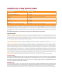
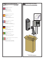
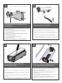
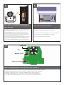
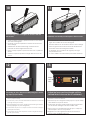
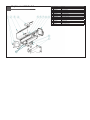
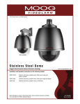
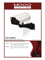
© 2012, Moog Videolarm, Inc. All Rights Reserved
ACH13HB8N
Aluminum Outdoor Environmental Camera Housings
www.moogvideolarm.com
Installation and Operation Instructions for the following models:
ACH13HB8N
Outdoor environmental housing for PoE plug enabled IP fixed cameras, wall/pole mount, dynamic (intelligent) power allocation heater/blower system, 30W midspan (100-240Vac input 50/60Hz)
ACH13HB8NE
Outdoor environmental housing for PoE plug enabled IP fixed cameras, wall/pole mount, dynamic (intelligent) power allocation heater/blower system
Before attempting to connect or operate this product, please read these instructions completely. 81-IN5455
06-26-2012
IMPORTANT SAFEGUARDS
1
Read these instructions.
2
Keep these instructions.
3
Heed all warnings
4
Follow all instructions.
5
Do not use this apparatus near water.
6
Clean only with damp cloth.
7
CAUTION
RISK OF ELECTRIC SHOCK
DO NOT OPEN
Do not block any of the ventilation openings. Install in accordance with the
manufacturers instructions.
8
9
SAFETY PRECAUTIONS
Cable Runs- All cable runs must be within permissible distance.
CAUTION: TO REDUCE THE RISK OF
ELECTRIC SHOCK, DO NOT REMOVE
COVER ( OR BACK). NO USER- SERVICEABLE PARTS INSIDE. REFER SEVICING
TO QUALIFIED SERVICE PERSONNEL.
Mounting - This unit must be properly and securely mounted to a supporting
structure capable of sustaining the weight of the unit.
Accordingly:
a. This installation should be made by a qualified service person and should conform
to all local codes.
b. Care should be exercised to select suitable hardware to install the unit, taking into
account both the composition of the mounting surface and the weight of the unit.
10 Do not install near any heat sources such as radiators, heat registers, stoves, or other
apparatus ( including amplifiers) that produce heat.
11 Do not defeat the safety purpose of the polarized or grounding-type plug. A
polarized plug has two blades with one wider than the other. A grounding type
plug has two blades and a third grounding prong. The wide blade or the third
prong are provided for your safety. When the provided plug does not fit into your
outlet, consult an electrician for replacement of the obsolete outlet.
12 Protect the power cord from being walked on or pinched particularly at plugs,
convenience receptacles, and the point where they exit from the apparatus.
13 Only use attachment/ accessories specified by the manufacturer.
14 Use only with a cart, stand, tripod, bracket, or table specified by the manufacturer,
or sold with the apparatus. When a cart is used, use caution when moving the cart/
apparatus combination to avoid injury from tip-over.
15 Unplug this apparatus during lighting storms or when unused for long periods of time.
16 Refer all servicing to qualified service personnel. Servicing is required when the
apparatus has been damaged in any way, such as power-supply cord or plug is
damaged, liquid has been spilled of objects have fallen into the apparatus, the
The lightning flash with an arrowhead symbol,
within an equilateral triangle, is intended to
alert the user to the presence of non-insulated
“dangerous voltage” within the product’s
enclosure that may be of sufficient magnitude
to constitute a risk to persons.
Este símbolo se piensa para alertar al usuario a la presencia
del “voltaje peligroso no-aisIado” dentro del recinto de los
productos que puede ser un riesgo de choque eléctrico.
Ce symbole est prévu pour alerter I’utilisateur à la presence
“de la tension dangereuse” non-isolée dans la clôture de
produits qui peut être un risque de choc électrique.
Dieses Symbol soll den Benutzer zum Vorhandensein der
nicht-lsolier “Gefährdungsspannung” innerhalb der
Produkteinschließung alarmieren die eine Gefahr des
elektrischen Schlages sein kann.
Este símbolo é pretendido alertar o usuário à presença “di
tensão perigosa non-isolada” dentro do cerco dos produtos
que pode ser um risco de choque elétrico.
Questo simbolo è inteso per avvertire I’utente alla presenza
“di tensione pericolosa” non-isolata all’interno della
recinzione dei prodotti che può essere un rischio di scossa
elettrica.
apparatus has been exposed to rain or moisture, does not operate normally, or
has been dropped.
Be sure to periodically examine the unit and the supporting structure to make sure that the integrity
of the installation is intact. Failure to comply with the foregoing could result in the unit separating
from the support structure and falling, with resultant damages or injury to anyone or anything struck
by the falling unit.
UNPACKING
Unpack carefully. Electronic components can be
damaged if improperly handled or dropped. If an item
appears to have been damaged in shipment, replace
it properly in its carton and notify the shipper.
Be sure to save:
1 The shipping carton and packaging material.
They are the safest material in which to make future
shipments of the equipment.
2 These Installation and Operating Instructions.
SERVICE
If technical support or service is needed, contact us at
the following number:
TECHNICAL SUPPORT
AVAILABLE 24 HOURS
1 - 800 - 554 -1124
The exclamation point within an equilateral
triangle is intended to alert the user to
presence of important operating and
maintenance (servicing) instructions in the
literature accompanying the appliance.
Este símbolo del punto del exclamation se piensa para
alertar al usuario a la presencia de instrucciones importantes
en la literatura que acompaña la aplicación.
Ce symbole de point d’exclamation est prévu pour alerter
l’utilisateur à la presence des instructions importantes dans
la littérature accompagnant l’appareil.
Dieses Ausruf Punktsymbol soll den Benutzer zum
Vorhandensein de wichtigen Anweisungen in der Literatur
alarmieren, die das Gerät begleitet.
Este símbolo do ponto do exclamation é pretendido alertar o
usuário à presença de instruções importantes na literatura
que acompanha o dispositivo.
Questo simbolo del punto del exclamaton è inteso per
avvertire l’utente alla presenza delle istruzioni importanti nella
letteratura che accompagna l'apparecchio.
Limited Warranty for Moog Videolarm Products
Moog Videolarm warrants these products to be free from defects in material or workmanship as follows:
PRODUCT CATEGORY
PARTS \ LABOR
AllEnclosuresandElectronics*
Five(5)Years
Poles/PolEvators™/CamEvator
Three(3)Years
WarriorSeries™/Q-View™/IRIlluminators
Five(5)Years
SViewSeries™
Five(5)Years**6monthsifusedinautoscan/touroperation
Controllers
Five(5)Years
PowerSupplies
Five(5)Years
EcoKit
Three(3)Years
AccessoryBrackets
Five(5)Years
LibertyDome
Three(3)Years
*DeputyDome™,NiteTrac™,IglooDome,PurgeDome™
Three(3)Years**6monthsifusedinautoscan/touroperation
During the labor warranty period, to repair the Product, Purchaser will either return the defective product, freight prepaid, or deliver it to Moog Videolarm
Inc. Decatur GA. The Product to be repaired is to be returned in either its original carton or a similar package affording an equal degree of protection with
a RMA # (Return Materials Authorization number) displayed on the outer box or packing slip. To obtain a RMA# you must contact our Technical Support
Team at 800.554.1124, extension 101. Moog Videolarm will return the repaired Product freight prepaid to Purchaser. Moog Videolarm is not obligated to
provide Purchaser with a substitute unit during the warranty period or at any time. After the applicable warranty period, Purchaser must pay all labor and/or
parts charges.
The limited warranty stated in these product instructions is subject to all of the following terms and conditions.
TERMS AND CONDITIONS
1. NOTIFICATION OF CLAIMS: WARRANTY SERVICE: If Purchaser believes that the Product is defective in material or workmanship, then written notice with an
explanation of the claim shall be given promptly by Purchaser to Moog Videolarm. All claims for warranty service must be made within the warranty period.
If after investigation Moog Videolarm determines the reported problem was not covered by the warranty, Purchaser shall pay Moog Videolarm for the cost of
investigating the problem at its then prevailing per incident billable rate. No repair or replacement of any Product or part thereof shall extend the warranty period
of the entire Product. The specific warranty on the repaired part only shall be in effect for a period of ninety (90) days following the repair or replacement of that
part or the remaining period of the Product parts warranty, whichever is greater.
2. EXCLUSIVE REMEDY: ACCEPTANCE: Purchaser’s exclusive remedy and Moog Videolarm’s sole obligation is to supply (or pay for) all labor necessary to repair any
Product found to be defective within the warranty period and to supply, at no extra charge, new or rebuilt replacements for defective parts.
3. EXCEPTIONS TO LIMITED WARRANTY:Moog Videolarm shall have no liability or obligation to Purchaser with respect to any Product requiring service during the
warranty period which is subjected to any of the following: abuse, improper use, negligence, accident, lightning damage or other acts of God (i.e., hurricanes,
earthquakes), modification, failure of the end-user to follow the directions outlined in the product instructions, failure of the end-user to follow the maintenance
procedures recommended by the International Security Industry Organization, written in product instructions, or recommended in the service manual for the
Product. Furthermore, Moog Videolarm shall have no liability where a schedule is specified for regular replacement or maintenance or cleaning of certain parts
(based on usage) and the end-user has failed to follow such schedule; attempted repair by non-qualified personnel; operation of the Product outside of the
published environmental and electrical parameters, or if such Product’s original identification (trademark, serial number) markings have been defaced, altered,
or removed. Moog Videolarm excludes from warranty coverage Products sold AS IS and/or WITH ALL FAULTS and excludes used Products which have not
been sold by Moog Videolarm to the Purchaser. All software and accompanying documentation furnished with, or as part of the Product is furnished “AS IS”
(i.e., without any warranty of any kind), except where expressly provided otherwise in any documentation or license agreement furnished with the Product. Any
cost associated with removal of defective product and installation of replacement product is not included in this warranty.
4. PROOF OF PURCHASE:The Purchaser’s dated bill of sale must be retained as evidence of the date of purchase and to establish warranty eligibility.
DISCLAIMER OF WARRANTY
EXCEPT FOR THE FOREGOING WARRANTIES, Moog Videolarm HEREBY DISCLAIMS AND EXCLUDES ALL OTHER WARRANTIES, EXPRESS OR IMPLIED,
INCLUDING, BUT NOT LIMITED TO ANY AND/OR ALL IMPLIED WARRANTIES OF MERCHANTABILITY, FITNESS FOR A PARTICULAR PURPOSE AND/OR
ANY WARRANTY WITH REGARD TO ANY CLAIM OF INFRINGEMENT THAT MAY BE PROVIDED IN SECTION 2-312(3) OF THE UNIFORM COMMERCIAL
CODE AND/OR IN ANY OTHER COMPARABLE STATE STATUTE. Moog Videolarm HEREBY DISCLAIMS ANY REPRESENTATIONS OR WARRANTY THAT
THE PRODUCT IS COMPATIBLE WITH ANY COMBINATION OF NON-Moog Videolarm PRODUCTS OR NON-Moog Videolarm RECOMMENDED PRODUCTS
PURCHASER MAY CHOOSE TO CONNECT TO THE PRODUCT.
LIMITATION OF LIABILITY
THE LIABILITY OF Moog Videolarm, IF ANY, AND PURCHASER’S SOLE AND EXCLUSIVE REMEDY FOR DAMAGES FOR ANY CLAIM OF ANY KIND
WHATSOEVER, REGARDLESS OF THE LEGAL THEORY AND WHETHER ARISING IN TORT OR CONTRACT, SHALL NOT BE GREATER THAN THE ACTUAL
PURCHASE PRICE OF THE PRODUCT WITH RESPECT TO WHICH SUCH CLAIM IS MADE. IN NO EVENT SHALL Moog Videolarm BE LIABLE TO PURCHASER
FOR ANY SPECIAL, INDIRECT, INCIDENTAL, OR CONSEQUENTIAL DAMAGES OF ANY KIND INCLUDING, BUT NOT LIMITED TO, COMPENSATION,
REIMBURSEMENT OR DAMAGES ON ACCOUNT OF THE LOSS OF PRESENT OR PROSPECTIVE PROFITS OR FOR ANY OTHER REASON WHATSOEVER.
!
English
Español
Français
Deutsch
Portuguese
Italiano
Electrical Specifications
Midspan
ACH13HB8N
Unpacking the Product
ACH13HB8N
Input Power: 100 to 240VAC
Power: .8A
Frequency: 50 to 60 HZ
Output
Camera: POE (55VDC)
Heater: 55VDC (max. 20W)
Energía de entrada: 100 a 240VAC:
Energía: .8A
Frecuencia: 50 a 60 hertzios
Salida:
Cámara: POE (55VDC)
Calentador: 55VDC (máximo 20W)
*
Puissance d'entrée : 100 à 240VAC
Puissance: .8A
Fréquence: 50 à 60 hertz
Rendement
Appareil-photo : POE (55VDC)
Réchauffeur : 55VDC (maximum 20W)
Zugeführte Energie: 100 zu 240VAC
Energie: .8A
Frequenz: 50 bis 60 Hz
Ausgang
Kamera: POE (55VDC)
Heizung: 55VDC (Maximum 20W)
Poder de entrada: 100 a 240VAC
Poder: .8A
Freqüência: 50 a 60 hertz
Saída
Câmera: Ponto de entrada (55VDC)
Calefator: 55VDC (máximo 20W)
Alimentazione in ingresso di entrata: 100 a 240VAC
Potere: .8A
Frequenza: 50 - 60 hertz
Uscita
Macchina fotografica: POE (55VDC)
Riscaldatore: 55VDC (massimo 20W)
* ACH13HB8N model only
1
2
Attach the bracket to the wall and secure
appropriately.
Connect housing to wall bracket.
• Una el soporte a la pared y asegúrelo
• Conecte la cubierta con el soporte de pared.
apropiadamente.
• Attachez la parenthèse au mur et la fixez
convenablement.
• Bringen Sie den Haltewinkel zur Wand an und
sichern Sie passend.
• Una o suporte à parede e fixe-o
apropriadamente.
• Fissi la staffa alla parete e fissi giustamente.
3
• Reliez le logement à la parenthèse de mur.
• Schließen Sie Gehäuse an Wandhaltewinkel an .
• Conecte a carcaça ao suporte de parede.
• Colleghi l'alloggiamento al supporto a mensola
4
Remove the (2) screws on top of the
housing and lift it open.
Install the (2) cable strain relief plugs on the bottom
of the housing and tighten with the locknuts.
• Quite (2) los tornillos encima de la cubierta y levántelos
abiertos.
• Instale (2) los enchufes del retenedor de cable del cable en el
fondo de la cubierta y apriete con las tuercas de fijación.
• Installez (2) les prises de passe-fils de câble sur le fond du logement
et serrez avec les contre-écrous.
• Bringen Sie die (2) Kabelgummidurchführungsringstecker auf
die Unterseite des Gehäuses an und ziehen Sie mit den
Kontermuttern fest.
• Instale (2) os plugues do protetor da fiação do cabo no fundo da
carcaça e aperte-os com as contraporcas.
• Installi (2) le spine di gommino di protezione del cavo sulla
parte inferiore dell'alloggiamento e stringa con i contro
dadi.
• Enlevez (2) les vis sur le logement et soulevez-les ouvertes.
• Entfernen Sie die (2) Schrauben auf das Gehäuse und heben
Sie sie geöffnet an.
• Remova (2) os parafusos no alto da carcaça e levante-os
abertos.
• Rimuova (2) le viti in cima all'alloggiamento ed alzile aperte.
6
5
Sled
Screw
Camera Sled
Place camera on sled and align mounting holes on
each. Adjust camera parallel to sled and tighten the
bolt on the bottom.
•
•
•
•
•
Coloque la cámara fotográfica en el trineo y alinee los agujeros de
montaje en cada uno. Ajuste la cámara fotográfica paralela al trineo y
apriete el perno en el fondo.
Placez l'appareil-photo sur le traîneau et alignez les trous de support sur
chacun. Ajustez l'appareil-photo parallèle au traîneau et serrez le
boulon sur le fond.
Setzen Sie Kamera auf Schlitten und richten Sie Entlüftungslöcher auf
jedem aus. Justieren Sie die Kamera, die zum Schlitten parallel ist und
ziehen Sie den Schraubbolzen auf der Unterseite fest.
Coloque a câmera no trenó e alinhe furos de montagem em cada um.
Ajuste a câmera paralela ao trenó e aperte o parafuso no fundo.
Disponga la macchina fotografica sulla slitta ed allinei i fori di montaggio su ciascuno. Registri la macchina fotografica parallela alla slitta e
stringa il bullone sulla parte inferiore.
7
Plug in RJ45 input and output cables.
• Enchufe los cables de entrada RJ45 y de la salida.
• Branchez les câbles de l'entrée RJ45 et du rendement.
• Schließen Sie Kabel des Einganges RJ45 und des Ausganges an.
• Obstrua dentro cabos da entrada RJ45 e da saída.
• Inserisca i cavi dell'input RJ45 e dell'uscita
Power Reset
LEDs
A
Network / Power
B
Network to Camera
Cable to camera (B), Network / Power (A). Unit is ready to power up.
•
•
•
•
•
Cablegrafíe a la cámara (b), red hacia / fuera (a). La unidad está lista para accionar para arriba.
Câblez à l'appareil-photo (b), le réseau / dehors (a). L'unité est prête à mettre sous tension.
Kabeln Sie zu Kamera (b), Netz / heraus (a). Maßeinheit ist bereit, oben anzutreiben.
Cabografe à câmera (b), rede / para fora (a). A unidade está pronta para pôr acima.
Cavo alla macchina fotografica (B), rete / fuori (A). L'unità è pronta ad alimentare in su.
TEST
Button
HEAT
8
Press the Calibration button for one second. Both the Test and Heat LED will turn ON. Once the unit has been
successfully calibrated, the Test and Heat LED will turn OFF. Once this is complete the Heat LED will turn ON only
if the heater is ON.
• Pulse el botón de calibración durante un segundo. Tanto la prueba y el calor se encenderá. Una vez que la unidad ha sido calibrado correctamente, la
prueba y el calor del LED se apagará. Una vez que se trata de completar el calor se encenderá sólo si el calentador está encendido.
• Appuyez sur le bouton d'étalonnage pour une seconde. Tant le test et la chaleur LED s'allume. Une fois l'appareil a été étalonné avec succès, le test et la
chaleur LED s'éteindra. Une fois cette opération terminée, la chaleur LED s'allume que si le chauffage est allumé.
• Drücken Sie die Taste Kalibrierung für eine Sekunde. Sowohl der Test-und Wärme-LED leuchtet auf. Sobald das Gerät erfolgreich kalibriert wurde, wird die
Test-und Wärme-LED auszuschalten. Sobald dies abgeschlossen ist die Wärme-LED leuchtet auf, wenn die Heizung an ist.
• Pressione o botão de calibração para um segundo. Tanto o teste como calor LED acenderá. Uma vez que o aparelho foi calibrado com sucesso, o teste
e calor LED apaga-se. Uma vez que este é completar o calor LED acenderá se o aquecedor está ligado.
• Premere il pulsante di calibrazione per un secondo. Sia il test e di calore LED si accende. Una volta che l'unità è stata correttamente calibrata, il collaudo
e calore LED si spegne. Una volta che questo è completare il calore LED si accende solo se il riscaldatore è ON.
9
! WARNING!
• The heater and blower will not start for 60 seconds after power is applied to the product.
• Wait for the camera to completely boot up before pressing the calibration button. This will allow for the most accurate calibration.
• El calentador y el ventilador no se iniciará durante 60 segundos después de la energía se aplica al producto.
• Espere a que la cámara para arrancar completamente antes de pulsar el botón de calibración. Esto permitirá la calibración más precisa.
• Le chauffage et de ventilation ne démarre pas pendant 60 secondes après mise sous tension est appliquée au produit.
• Attendez que l'appareil photo à démarrer complètement avant appuyant sur le bouton d'étalonnage. Cela permettra pour le calibrage le
plus précis.
• Die Heizung und das Gebläse wird nicht für 60 Sekunden nach dem Einschalten starten, um das Produkt angewendet wird.
• Warten Sie, bis sich die Kamera komplett hochfahren, bevor Sie die Kalibrierung Taste. Dies wird für die genaue Kalibrierung ermöglichen.
• Aquecedor e soprador A não será iniciado durante 60 segundos após a energia é aplicada ao produto.
• Aguarde até que a câmera completamente arrancar antes de premir o botão de calibração. Isto irá permitir a calibração mais precisas.
• Il riscaldamento e soffiante non inizierà per 60 secondi dopo l'alimentazione è applicata al prodotto.
• Attendere che la macchina fotografica per avviare completamente a prima di premere il pulsante di calibrazione. Questo permetterà la
taratura più accurata.
10
11
Close the top cover and tighten to the base with the
hex screws.
If desired, use security screws in place of hex screws.
• Cierre la cubierta superior y apriete a la base con los tornillos
de la tuerca hexagonal.
• Si está deseado, utilice los tornillos de la seguridad en
lugar de los tornillos de la tuerca hexagonal.
• Fermez la couverture supérieure et serrez à la base avec les
vis de sortilège.
• Si désiré, utilisez les vis de sécurité au lieu des vis de sortilège.
• Schließen Sie die obere Abdeckung und ziehen Sie zur
Unterseite mit den Hexagonschrauben fest.
• Wenn Sie gewünscht werden, benutzen Sie die Sicherheit
Schrauben anstatt der Hexagonschrauben.
• Feche a tampa superior e aperte-a à base com os parafusos
do hex.
• Se desejado, use os parafusos da segurança no lugar
dos parafusos do hex.
• Chiuda la copertura superiore e stringa alla base con le viti
del hex.
• Se voluto, utilizzi le viti di sicurezza al posto delle viti del hex.
12
13
Adjust
Lens
Here
If mounting to pole, attach assembly using 3/4” mounting straps (not provided).
Adjust the focus and focal length until the
desired field of view and focus is obtained.
•
Si monta al poste, una a asamblea usando las correas que montan del
3/4"(no proporcionadas).
• Ajuste el foco y la longitud focal hasta que el campo visual
•
Si montant au poteau, attachez l'assemblée en utilisant les courroies de
montage de 3/4"(non fournies).
• Ajustez le foyer et la longueur focale jusqu'à ce que le champ
•
Bei der Befestigung zum Pfosten, bringen Sie Versammlung mit 3/4"den
Befestigungsbügeln an (nicht bereitgestellt).
• Justieren Sie den Fokus und die fokale Länge, bis gewünscht
•
Se montando ao pólo, una o conjunto usando as cintas de montagem
de 3/4"(não fornecidas).
• Ajuste o foco e o comprimento focal até que o campo de
•
Se montando al palo, fissi il complessivo usando le cinghie di montaggio di 3/4"(non fornite).
• Registri il fuoco e la lunghezza focale fino ad ottenere il
deseado y el foco se obtiene.
visuel désiré et le foyer soit obtenu.
von der Ansicht auffangen und Fokus erhalten wird.
vista desejado e de foco esteja obtido.
campo voluto di visibilità ed il fuoco.
Replacement Parts List
ACH13HB8N
12
#
Part Number
Description
1
RPACH010
ACH13 Front Endcap Assembly
2
RPACH020
ACH13 Lid Screws
3
RPHACH8N
Heater for POE housing
4
RPACH050
12V Heater & Thermostat Kit For ACH13
5
RPACH060
ACH13 Top Extrusion
6
7
RPACH070
RPBACH8N
ACH13 Bottom Extrusion
Blower for POE housing
8
RPPCBPOE
9
RPACH110
PC board for POE housing
ACH13 Rear Endcap Assembly
10
RPACHPK
Packet Assembly
11
WM800
Medium Duty Wall Mount Bracket For ACH13
12
ACH130
ACH13 Vent Hole Plugs
Product Registration/Warranty
Thank you for choosing Moog Videolarm. We value your patronage and are solely committed to providing you with the highest
quality products available and superior customer service. Should a problem arise, rest assured that Moog Videolarm stands behind its products by offering impressive 3 Year and 5 Year warranties, depending on the product
purchased. See full warranty details at www.moogvideolarm.com/technical-support/warranty-plan/
Register Your Products Online
Please take a few moments to register your purchase via the Online Product Registration Form at:
www.moogvideolarm.com/technical-support/product-registration
Register your recent Moog Videolarm purchase and benefit from the following:
• Simple and Trouble-Free RMA process
• Receive product updates, and special promotion
• Eliminate the need to archive original purchase documents:
Receipts, Purchase Orders, etc…