1
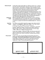
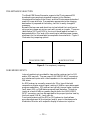
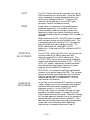
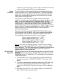
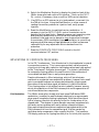
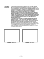
OPERATING AND MAINTENANCE
INSTRUCTION MANUAL
MODEL 708
FM-STEREO GENERATOR
__________
—– USER’S RECORD —–
Model 708 - Serial No. _______
Date Purchased _____________
Warranty Card Mailed — ¨
OPERATING AND MAINTENANCE
INSTRUCTION MANUAL
MODEL 708
FM-STEREO PROCESSOR / GENERATOR
September, 1995
1305 Fair Avenue, Santa Cruz, CA
95060
TEL: (408) 458-0552 – FAX: (408) 458-0554
TABLE OF CONTENTS
Section I - INTRODUCTION
Model 708 Product Description ........................................................................................... 3
General - Features
Audio Pre-Processing Requirements ................................................................................... 3
Pre-emphasized Transmission - Split-Spectrum Peak Control Internal Overmod Protection
Model 708 Technical Specifications..................................................................................... 4
Patent Notice ........................................................................................................................ 5
Block Diagram ...................................................................................................................... 6
Section II - Installation
Unpacking and Inspection ................................................................................................... 7
Mounting ............................................................................................................................... 7
Rack Requirements - Heat Dissipation
AC (Mains) Power ................................................................................................................. 7
As Delivered - Voltage Selector - Power Cord
Radio Frequency Interference (RFI) .................................................................................... 8
Location - Ground Loops
Line Input and Input Range Selection ................................................................................. 8
Input Connections - Balanced Inputs - Unbalanced Inputs Input Gain Range - Gain Jumpers
Pre-Emphasis Selection ....................................................................................................... 9
Subcarrier Inputs................................................................................................................. 10
Composite Output .............................................................................................................. 11
Output Ground Loops
Section III - Setup and Operation
Panel Controls and Indicators ........................................................................................... 12
(All Controls and Indicators Defined According to Function)
Normal Setup Procedure .................................................................................................... 15
Input Gain Calibration - Pilot and Subcarrier Adjustments Output Pre-Check - Output Level Adjustment
— 1 —
Implications of Composite Processing ............................................................................. 17
Pilot Modulation - Out-of-Band Components
Section IV - Calibration
Calibration .......................................................................................................................... 20
Equipment Required - Power Supply Check - Clock Set Input Level Set - Low-Pass Filter Matching - Crosstalk Trim Input Level Calibration - Output Level Calibration Stereo Pilot Distortion Null - Subcarrier Calibration Separation Trim
Section V - Circuit Descriptions
Circuit Descriptions ............................................................................................................ 25
Component Annotation - Input Circuitry Filter Overshoot Compensator - Low-Pass Filter Pilot and Subcarrier Generation - Bargraph Meter Power Supply
Section VI - Appendix
Parts Lists - Schematics - Warranty .............................................................................. 33
— 2 —
Section I
INTRODUCTION
MODEL 708 PRODUCT DESCRIPTION
General
Inovonics introduced its first FM-Stereo Generator in 1992. The
original Model 705 was the hallmark of simplicity, and was intended to
answer the more basic of FM radio broadcasting needs.
The Model 708 includes several additional features, and boasts
performance superior to that of its predecessor. Through efficient
manufacturing techniques and automated calibration procedures, the
708 maintains the tradition of a value leader among FM Stereo
Generators.
Features
Features of the Inovonics 708 include:
•
Accurate front-panel metering of the input program,
externally-applied subcarriers, and output signal
levels.
•
Built-in, metered combining for two external (RDS or
SCA) subcarrier sources.
•
Extended-response low-pass filtering with proprietary
overshoot compensation.
•
Digital synthesis of pilot and subcarrier for unexcelled
performance and freedom from drift and routine
adjustment.
•
Built-in, adjustable Composite Processor.
AUDIO PRE-PROCESSING REQUIREMENTS
The Inovonics 708 Stereo Generator incorporates two separate circuits
to safeguard against carrier overmodulation (over-deviation).
Nonetheless, it is anticipate that the 708 will be preceded by some form
of “audio processing” system which places a ceiling on program peaks
with specific allowances for protection of the pre-emphasis
characteristic. It is essential that this need for split-spectrum audio
processing be understood and met.
Pre-emphasized
Transmission
FM broadcasting practice imparts a high-frequency pre-emphasis
(high-end boost) to the input program signal prior to transmission. At
the receiver a complementary de-emphasis (high-end rolloff) network
restores overall flat frequency response. The purpose of this exercise is
to reduce the high frequency noise which is invariably added in
transmission. This noise is generally worse for listeners who are some
— 3 —
transmission. This noise is generally worse for listeners who are some
distance from the broadcasting station.
If a low frequency tone of, say, 300Hz is applied to the transmitter at a
level which yields full carrier modulation (100% or ±75kHz deviation),
a high frequency tone of 10kHz applied at this same input level would
overmodulate the carrier (400% or more!) because of the transmission
pre-emphasis equalization. Normal voice and music programs have
comparatively low energy at the higher frequencies, and actual
statistics of program spectral composition were taken into account
when pre-emphasis characteristics were established years ago.
Nevertheless, occasional high energy, high frequency peaks (sibilants,
cymbals, etc.) can still cause carrier overmodulation, even when
program peaks are broadband-limited to 100%-modulation values.
This is especially true when modern-day recordings of contemporary
music constitute the program source.
Split-Spectrum
Peak Control
Internal
Overmod
Protection
A pre-emphasis network ahead of a broadband limiter, and a deemphasis circuit following it, will deal with this situation, although the
overall level will “duck” whenever a high-end peak occurs. This
imparts a “choppy” sound to the program and reduces both
intelligibility and perceived loudness. What is instead required is a
program limiter operating as a dual-band device; a broadband section
to cope with normal program peaks, and an independent highfrequency limiter (with proportionally faster time constants) to deal
with those program components accentuated by the transmission preemphasis characteristic. A limiter of this type, now common in both
FM and AM broadcasting systems, has negligible audible effect on most
program material while providing absolute protection from carrier
overmodulation. Comprehensive FM audio processing systems are
available from Inovonics, and from a number of other suppliers.
Overmodulation protection circuitry internal to the 708 starts with a
complex, active peak clipper integral with the patented low-pass filter
overshoot compensator. Because of its unique mode of operation, a
good deal more peak clipping may be tolerated than with more simple
audio clipping circuits. The 708 may, in fact, even be used “barefoot,”
or with minimal audio pre-processing, yet still yield acceptable
performance.
The 708 also features a built-in Composite Processor which can be
adjusted to clip as much as 3dB into the multiplex signal. This clipping
is performed prior to injection of the 19kHz stereo pilot and any
auxiliary subcarriers. While this “composite clipping” technique is
routinely used to increase perceived loudness, it is at the expense of
introducing spurious harmonic products above the 54kHz upper bandedge of the composite stereo signal. Please refer to the further
discussion on Page 17.
— 4 —
MODEL 708 TECHNICAL SPECIFICATIONS
Frequency Response (with preemphasis turned OFF, or through
appropriate de-emphasis network):
±0.5dB, 20Hz–15kHz; –1dB or
less at 16kHz, –60dB or better at
19kHz.
SCA / RDS Inputs:
10K-ohms, unbalanced; accept
SCA or RDS subcarriers at 0dBu
or greater levels for nominal 5% to
10% subcarrier injection, relative
to 100% modulation.
Stereo Separation (LàR or RàL):
>65dB, 20Hz–16kHz.
Pre-emphasis:
May be jumpered for 75µs or 50µs
characteristic; may be switched
OFF at front-panel.
Distortion (1dB below 100%
modulation):
<0.1% THD in demodulated
audio.
Noise:
Better than 80dB below 100%
modulation in demodulated audio,
20Hz–16kHz. 38kHz residual and
“digital” noise above 54kHz,
–70dB or better.
Composite Processor:
Adjustable between 0dB and 3dB
clipping of the 100%-modulated
multiplex waveform prior to
19kHz pilot insertion.
Composite (Multiplex) Output:
Adjustable between 2V p-p and
8V p-p; 75-ohm source impedance.
Crosstalk (MàS or SàM):
Linear and nonlinear crosstalk,
–50dB or better.
Digital Synthesis Sampling Rate:
608kHz (16X subcarrier
oversampling).
Stereo Pilot:
19kHz, ±1Hz; injection level
adjustable between 7% and 12%,
relative to 100% modulation.
Power Requirements:
105–130VAC or 210–255VAC,
50/60Hz; 15 watts.
Program Line Inputs:
Active-balanced/bridging;
accommodate input levels between
–10dBu and +20dBu, equivalent
to 100% modulation.
Size and Weight:
1¾”H x 19”W x 7”D (1U);
7 lbs (shipping).
BLOCK DIAGRAM
A simplified Block Diagram of the Model 708 is shown on the following
page. Generator circuitry is explained in detail under Circuit
Descriptions, Section V, which references Schematic Diagrams found in
the Appendix, Section VI.
PATENT NOTICE
Low-pass filter overshoot compensation circuitry used in the Inovonics
708 is protected under U.S. Patent No. 4,737,725.
— 5 —
Figure 1 - Block Diagram, Model 708 FM-Stereo Generator
— 6 —
Section II
INSTALLATION
UNPACKING AND INSPECTION
Immediately upon receipt of the equipment, inspect carefully for any
shipping damage. If damage is suspected, notify the carrier at once,
then contact Inovonics.
It is recommended that the original shipping carton and packing
materials be saved for future reshipment. In the event of return for
Warranty repair, shipping damage sustained as a result of improper
packing for return may invalidate the Warranty!
IT IS VERY IMPORTANT that the Warranty Registration
Card found at the front of this Manual be completed and
returned.
Not only does this assure coverage of the
equipment under terms of the Warranty, and provide some
means of trace in the case of lost or stolen gear, but the user
will automatically receive specific SERVICE OR MODIFICATION INSTRUCTIONS should they be issued by Inovonics.
MOUNTING
Rack
Requirement
Heat Dissipation
Inovonics’ Model 708 is packaged to mount in a standard 19-inch
equipment rack and requires only 1¾ inches (1U) of vertical rack
space. The use of plastic “finishing” washers is recommended to
protect the painted finish around the mounting holes.
Consuming no more power than a bedside clock radio, heat generated
by the 708 is insignificant. The unit is specified for operation within
an ambient temperature range from freezing to 120°F/ 50°C. Because
adjacent, less efficient equipment may radiate substantial heat, be sure
that the equipment rack has sufficient ventilation to keep the
temperature below the stated maximum.
AC (MAINS) POWER
As Delivered
Unless specifically ordered for export shipment, the Model 708 is set at
the factory for operation from 115V, 50/60Hz AC mains. The rearpanel designation next to the fuseholder will confirm both the mains
voltage selected and the value of the fuse supplied.
— 7 —
Voltage Selector
A mains voltage selector switch is located beneath the top cover of the
unit, adjacent to the AC mains connector on the circuit board. With
primary AC power disconnected, slide the red actuator with a small
screwdriver so that the proper mains voltage (115 or 230) is visible.
You must always install an appropriate fuse, and should check that the
rear-panel voltage/fuse designation is properly marked. It is factory
practice to cross-out the inappropriate designation with an indelible
black marking pen. You can remove this strikethrough with solvent to
redesignate.
BE SURE that the mains voltage selector setting and primary fuse value are appropriate for the mains supply before
plugging the 708 into the wall outlet.
Power Cord
The detachable power cord supplied with the 708 is fitted with a
North-American-standard male plug. The individual cord conductors
are supposed to be color-coded in accordance with CEE standards:
BROWN = AC “HOT”
BLUE = AC NEUTRAL GRN/YEL = GROUND
If this turns out not to be the case, we offer our apologies (cord vendors
vary) and advise that U.S. color coding applies:
BLACK = AC “HOT”
WHITE = AC NEUTRAL
GREEN = GROUND
RADIO FREQUENCY INTERFERENCE ( R F I )
Location
Ground Loops
Although we have anticipated that the 708 will be operated in close
proximity to high-power transmitters, you should exercise care in
locating the unit away from abnormally high RF fields.
In some installations a mains frequency or RF ground loop may be
formed between the input or output cable shield grounds and the AC
power cord ground. Use of a “ground-lifting” AC adapter should
remedy the situation, though the chassis ultimately must be returned
to earth ground for safety. Generally, being screwed-down in the
equipment rack will satisfy this requirement.
LINE INPUT AND INPUT RANGE SELECTION
Input
Connections
The Inovonics 708 has electronically-balanced (transformerless) leftand right-channel PROGRAM LINE INPUTS. These are brought out to
a screw-terminal barrier strip on the rear panel and include chassis
ground connections for cable shields. Please note that the screwterminal barrier block can be unplugged from the chassis! This makes
initial connection easier and permits quick removal of the 708 from the
rack should maintenance ever be required.
— 8 —
Balanced Inputs
Unbalanced
Inputs
Input Gain
Range
A balanced program audio feed to the 708 will use both the + and the –
terminals, plus the associated G (ground) terminal for each of the two
stereo channels. Since these are “bridging” (high impedance) inputs,
they provide no termination for an audio processor or other equipment
which feeds the 708. Please feel at liberty to connect a 600-ohm
resistor across the input terminals should you feel this really
necessary. Most professional equipment nowadays features low output
impedances and high input impedances. The concept of 600-ohm “linematching” dates from the age of transformer coupling and is rooted in
the mystique of telephone engineering. More often than not, audio line
impedance matching is ignored by today’s enlightened broadcasters
(you) and leading-edge equipment manufacturers (us).
When the generator is fed from a test oscillator or other equipment
with unbalanced outputs, the single center conductor of the shielded
input lead should be connected to the + terminal, and the shield to G.
In addition, a jumper wire should be installed between the – terminal
and G.
The 708 can accommodate line-level program inputs with a nominal
“Zero-VU” value between –10dBu and +20dBu. This 30dB range is
divided into two 15dB ranges by internal jumpering.
As shipped, the generator is jumpered for “professional” input levels
between +5dBu and +20dBu, corresponding to 100% modulation.
Most processor and STL receiver outputs will fall into this range,
+6dBu, +8dBu and +10dBu being typical levels.
Lower levels, between –10dBu and +5dBu, may be encountered with
feeds via lossy studio-transmitter telephone line circuits. The extra
gain for the low-level range is enabled by changing jumpers beneath
the top cover.
Gain Jumpers
Under the top cover, and just behind the PROGRAM LINE INPUT
barrier strip, you will find two jumper pin strips, each with a “pushon” jumper. The strips are identified as JMP2 and JMP3 in the circuit
board legend, and each has an H and an L marking to indicate the
proper jumper placement for high level and for low level inputs,
respectively. Figure 2 illustrates jumpering options.
HIGH LEVEL INPUTS
(+5dBu to +20dBu)
LOW LEVEL INPUTS
(–10dBu to +5dBu)
Figure 2 - PROGRAM LINE INPUT Range Selection
— 9 —
PRE-EMPHASIS SELECTION
The Model 708 Stereo Generator supports the 75-microsecond FM
broadcasting pre-emphasis standard common to the Western
Hemisphere and parts of the Orient, and the 50-microsecond standard
used in Europe and Asia. Pre-emphasis appropriate to the shipping
destination is jumpered at the factory, but this is easily changed if
necessary.
Beneath the top cover and about two inches behind the input barrier
strip are two jumper pin strips, each with a push-on jumper. These are
identified as JMP1 and JMP4 in the circuit board legend, and each is
designated with a 75µs and a 50µs marking to indicate proper jumper
placement for the two available pre-emphasis characteristics. Figure 3
illustrates the jumpering options
75-MICROSECOND
50-MICROSECOND
Figure 3 - Pre-emphasis Jumpering
SUBCARRIER INPUTS
Internal combining is provided for two auxiliary subcarriers for SCA
and/or RDS services. The rear-panel SUBCARRIER INPUT connectors
are unbalanced inputs with a load impedance in the neighborhood of
10K-ohms.
An RDS subcarrier normally accounts for 5% or less of the total
composite multiplex output signal, making it 26dB or more below peak
program modulation. SCA subcarriers typically have a higher injection
level, about 10%, or 20dB below program peak deviation. Subcarrier
inputs at a level of 0dBu or greater may be fed to the SUBCARRIER
INPUT connectors, and can be regulated to the proper injection level by
the front-panel SUB INJ. level controls.
Front-panel metering of the RDS or SCA subcarrier levels allows
accurate adjustment of the injection level(s), even in the absence of a
Modulation Monitor with a specific display of subcarrier injection.
— 10 —
COMPOSITE OUTPUT
The unbalanced COMPOSITE OUTPUT of the Inovonics 708 has a
resistive source impedance of 75 ohms. This permits runs of moderate
length (about 50 feet, maximum) to the exciter or microwave link input.
If the cable length is more than just a few feet, the cable should, itself,
have a 75-ohm characteristic impedance and be terminated in 75 ohms
at the far end.
A Stereo Generator must always be connected to an exciter or link (STL)
input specifically intended for multiplex stereo. This is a “flat” input,
rather than a monaural program input with signal pre-emphasis.
Program signal pre-emphasis is imparted by the 708.
Output Ground
Loops
Because the Stereo Generator output and the exciter input are both
unbalanced, it is best to locate the 708 near the exciter and power both
from a common AC mains circuit. This will help avoid ground loops
and mains-related hum in the transmitted signal.
— 11 —
Section III
SETUP AND OPERATION
PANEL CONTROLS AND INDICATORS
A brief description of the front-panel controls and indicators is given
here. Do scan this section to at least verify that our terminology agrees
with yours.
PLEASE NOTE that all front-panel multi-turn trim controls require
fifteen to twenty complete rotations of the adjusting screw to cover their
total operating range. Depending on the trim-pot manufacturer, the end
of the range may, or may not, be identified by a “click-click” sound or
other audible/tactile sensation.
INPUT GAIN
These two controls at the far-right end of the front
panel adjust the 708’s input sensitivity for the nominal
program level applied to the LEFT and RIGHT channel
PROGRAM LINE INPUT barrier strip terminals on the
rear panel. The controls have a 15dB range which is
multiplied by input gain range jumpering to an input
acceptance range of 30dB (see Page 9). The INPUT
GAIN controls are adjusted so that the 100%modulation “ceiling” imposed by Model 708 internal
circuitry coincides with the input program peak level
which corresponds to 100% modulation.
PRE-EMPHASIS
System pre-emphasis is imparted by the Stereo
Generator in most situations. With the front-panel
PRE-EMPHASIS switch IN, the selected characteristic
(see Page 10) is enabled and the attendant green LED
will light. If, on the other hand, pre-emphasized audio
is applied to the 708, the switch should be set to the
OUT position to avoid “double” pre-emphasis. This
alternate mode is indicated by the red LED.
O’SHOOT COMP.
The Model 708 incorporates a patented overshoot
compensation circuit which inhibits overshoots in the
primary 16kHz audio low-pass filter sections. The
switch is normally left in the IN position, indicated by
the green LED. Compensation may be switched OUT
for system tests which require carrier deviation in
excess of 100% (maximum); this will light the red LED.
The yellow LED to the right of the green one displays
circuit action and will flash almost continuously when
“bright” music is being broadcast.
— 12 —
PILOT
The PILOT switch lets the user manually turn off the
19kHz stereo pilot for certain tests. Since the 19kHz
pilot is necessary for proper system operation, the
switch should always be left ON. The green LED
indicates normal operation, the red LED lights
whenever the pilot has been turned off.
MODE
Under some circumstances it may be advisable to
broadcast monaurally. For example, should the
station suddenly suffer an emergency power loss,
temporarily reverting to mono transmission would
help regain some of the lost coverage until full power is
restored.
When switched to MONO, the MODE switch removes
both the stereo subcarrier and the 19kHz pilot. The
transmitted signal will consist of L+R, the algebraic
sum of the left and right program channels. The
MODE switch does not remove RDS or SCA
subcarriers. Green and red LEDs indicate the MODE
selection.
COMPOSITE
ADJUSTMENTS
The PILOT INJ. and SUB 1/SUB 2 INJ. controls set the
injection levels of the 19kHz stereo pilot and
externally-applied SCA or RDS subcarrier(s). The
OUTPUT LEVEL control varies the overall composite
output level delivered to the exciter or STL. OUTPUT
LEVEL is a “master” adjustment and does not affect
the relationships (level ratios) between the stereo
program, pilot and RDS/SCA subcarrier.
MPX EQUAL. is a composite (multiplex) equalization
trimmer in the output stage of the 708. This has been
factory-set for best stereo separation into a resistive
load, but can be used to compensate for frequency
response deficiencies in a composite STL or in the
input section of the exciter.
COMPOSITE
PROCESSING
In the fully-counterclockwise OUT position, an output
“safety” clipper acts on only those very fast program
peaks and overshoots which sneak by the earlier
protection circuitry. As the COMPOSITE
PROCESSING control is rotated clockwise, the level
applied to the safety clipper is increased by the dB
value indicated on the front panel. Composite clipping
will increase apparent loudness, but at the expense of
generating some spurious harmonic products. The
tabulation at the top of the next page is approximate;
please refer to the discussion about additional
implications of composite clipping on Page 17.
— 13 —
COMPOSITE
PROCESSING
PEAK VALUE OF
CLIPPING PRODUCTS
OUT
>60dB below 100%
1dB
50dB below 100%
2dB
45dB below 100%
3dB
40dB below 100%
Composite clipping is performed prior to injection of
the 19kHz stereo pilot and any subcarriers. This
averts pilot clipping or other pilot amplitude
modulation. Nevertheless, crosstalk of the program
audio into RDS or SCA subcarriers is exacerbated by
composite clipping and its inevitable intermodulation
and harmonic generation. Use this feature sparingly!
“MULTIMETER”
POWER
An up/down momentary toggle switch cycles the frontpanel metering among the various display options;
LEDs identify the function monitored. The metered
values are:
L
Left program input channel.
R
Right program input channel.
L+R
The sum of the left and right channels.
L–R
The difference of the left and right
channels.
MPX
The composite multiplex output.
PILOT
The 19kHz stereo pilot.
SUB 1
Subcarrier #1
SUB 2
Subcarrier #2
(Sorry, the function of this switch is classified.)
BARGRAPH METERING
The front-panel bargraph meter is useful in initial level-setting and to
verify proper operation of the 708 Stereo Generator. The up/down
switch to the right of the display cycles the meter through its various
measurement functions.
The meter is peak-responding, and is scaled both in percent-modulation
and in dB, with 0dB corresponding to 100% modulation. When switched
to show measurements of PILOT, SUB 1 or SUB 2, an additional 20dB
— 14 —
(10X) circuit gain re-scales the measurements for these lower-level
signals. For these measurements, the 100% marking should be read as
10%, and 0dB as –20dB.
NORMAL SETUP PROCEDURE
This setup procedure presupposes a normal installation with the Model
708 PROGRAM LINE INPUT fed directly from the output of a properly
adjusted audio processor. As explained on Pages 3 and 4, the processing
system must maintain program peaks at a ceiling value corresponding to
100% modulation, and incorporate “pre-emphasis protection”
(independent high frequency) limiting in addition to broadband peak
control. This procedure further supposes a direct connection of the
COMPOSITE OUTPUT to the wideband input of an exciter/transmitter.
Variations from these conditions, such as an intermediate STL or other
link, analog or digital, in either the input or the output path of the 708,
may call for considerations not addressed here.
At this point the 708 should be installed in the program chain with
power applied, and have all front-panel function switches ON.
Input Gain
Calibration
1. Double-check PC board jumpering options for proper line input
range selection and for proper pre-emphasis selection.
2. Feed the audio processor left channel input, only, with a 500Hz
sinewave test signal which yields 6dB to 10dB of indicated signal
limiting. This should drive the processor left channel line output to
its “ceiling” value and present the left channel input of the 708 with
a signal representing 100% modulation of that channel.
NOTE: Good engineering practice prescribes a standardized audio line
level at any equipment interface. This facilitates setup,
troubleshooting, and “patching” alternate gear in and out of the
program signal path. Take this opportunity to set the output level
of the processing system at a preferred “zero-dB” level: +6dBm,
+10dBm, or any other value common to station operation.
3. Set the bargraph meter to measure left channel (L) level. Adjust L
INPUT GAIN for a 0dB, or 100%, indication.
4. Repeat steps 1 -3 for the right program channel. Be sure that only
the right channel input of the processing system is driven.
Pilot and
Subcarrier
Adjustments
1. Set the bargraph meter to measure PILOT. Adjust the 19kHz stereo
pilot (PILOT INJ.) control for desired injection; typically 9%. Keep
in mind that the 100% point on the meter is actually 10% for this
measurement.
2. Cycle the meter to read any subcarriers applied to the 708. The
SUB 1 INJ. and SUB 2 INJ. controls may be adjusted for the desired
injection levels for subcarriers. Typically, RDS subcarriers are set
to about 5%, SCA subcarriers to 10%. Again, the 100% mark on the
— 15 —
to about 5%, SCA subcarriers to 10%. Again, the 100% mark on the
meter should be read as 10% for these measurements.
Output
Pre-check
The initial portion of the output adjustment procedure is performed
under simulated “on-air” operating conditions. Feed typical program
material to the stereo generator via the processing system, but stereo
temporarily disconnected the generator from the exciter until the precheck verifies normal operation.
The processor, itself, should now indicate normal values of gain
reduction, including a minimum of 6dB peak limiting of program audio
peaks. Under this condition the 708 bargraph display will show
consistent left (L) and right (R) channel signal activity peaking at 0dB.
A display much in excess of 0dB indicates limiter overshoots and a
possible deficiency of the processing system in maintaining a consistent
output “ceiling.” Occasional overshoots up to +1dB or +2dB are to be
expected, but anything above these values is cause to question
processing effectiveness.
Temporarily set the front-panel COMPOSITE PROCESSING control
fully clockwise to the 3dB point. With typical program audio applied,
check bargraph metering of the composite multiplex output (MPX).
Peak modulation should remain within the limits shown:
Stereo program modulation only — 100%
Stereo program and RDS only — 105%
Stereo program and one SCA only — 110%
Stereo program, RDS and SCA — 115%
Stereo program and two SCAs — 120%
NOTE: MPX metering relates to the total composite output voltage
peak excursion before the OUTPUT LEVEL control, not the actual FM
carrier deviation. The 100% reference point represents a normal stereo
signal without subcarriers; actual measurements will reflect the
algebraic addition of any subcarriers.
OUTPUT LEVEL
Adjustment
PLEASE be certain that you understand operation of the station ModMonitor, and that it is properly calibrated and connected to the correct
transmitter/exciter RF sample point. The remainder of this procedure
is performed “on-air.”
1. Turn the 708 OUTPUT LEVEL control fully counterclockwise and
connect the generator’s COMPOSITE OUTPUT to the input of the
exciter.
2. Turn off or disconnect any subcarrier inputs to the 708. With only
the stereo programming applied, advance the OUTPUT LEVEL
control for a Mod-Monitor indication of frequent 100%-modulation
peaks.
3. Back-down the OUTPUT LEVEL control slightly, so that the 100%
peak flasher(s) light only occasionally.
— 16 —
4. Switch the Modulation Monitor to display the injection level of the
19kHz stereo pilot and confirm 9% injection. Touch-up the PILOT
INJ. control, if necessary, then re-confirm 100% carrier deviation.
5. If an RDS or an SCA subcarrier is to be broadcast, re-connect it to
the 708 at this time. Using the Mod-Monitor, or other means of
reading the auxiliary subcarrier injection level, verify proper
injection.
6. Reset the Mod-Monitor to read total carrier modulation. If
necessary, trim the OUTPUT LEVEL control to maintain carrier
deviation within legal limits. Depending on current operating rules
and practices, when either an SCA or an RDS subcarrier is
broadcast, total peak carrier deviation may be permitted to exceed
the customary 100%-modulation figure. The station (or consulting)
engineer should be aware of legal guidelines in effect and assume
responsibility for any adjustment which deviates from this
procedure.
7. Reset the COMPOSITE PROCESSING control to the fullcounterclockwise, OUT position.
IMPLICATIONS OF COMPOSITE PROCESSING
In the FM “loudness war,” the ultimate tool in the broadcaster’s arsenal
is composite processing. This is more appropriately called composite
clipping since linear gain-reduction techniques cannot easily be applied
to the “interleaved” multiplex stereo signal. The historic justification
for composite clipping reflects the need to control the overshoots of
uncorrected low-pass filters in early stereo generators.
Despite refinements in filter technology, which all but eliminate
overshoot as a potential overmodulation problem, it seems that a small
gain in perceived loudness can always be achieved by clipping peak
excursions of the multiplex signal just before it is fed to the exciter.
This clipping action is not without certain tradeoffs, however, among
which are modulation of the 19kHz stereo pilot and the generation of
out-of-band distortion components.
Pilot Modulation
The 19kHz stereo pilot, already at a level some 20dB below 100%
modulation, is subject to amplitude perturbations by program peaks
when overall composite clipping is employed. With more than about
1dB of clipping, the pilot can actually be lost for the duration of the
clipped peak. The receiver’s stereo decoder may even lose phase-lock;
this was a serious problem with early add-on composite clippers.
More sophisticated stand-alone composite clipping devices strip the
19kHz stereo pilot from the composite signal, clip the remaining
multiplex stereo components, then re-apply the pilot. The Inovonics
708 simply performs its clipping function prior to initial pilot injection.
— 17 —
Out-of-Band
Components
Simple clipping of a symmetrical waveform will invariably generate
odd-order harmonics of the fundamental frequency. The level of, and
signal degradation by, these harmonics will depend in large part on the
depth of the clipping action. Because of its complementary pre- and deemphasis, FM broadcasting can forgive a surprising amount of
baseband clipping, insofar as audible distortion is concerned.
Nonetheless, clipping products can clutter that part of the baseband
spectrum reserved for RDS and SCA subcarriers, potentially creating
crosstalk into those services. With one or two dB of clipping, distortion
products will probably be tolerable. Much more clipping than this will
not only compromise subcarrier services, but can interfere with
adjacent stations as well.
Figures 4a through 4d reveal out-of-band components generated by
composite clipping. These “worst case” examples were created by
feeding a stereo generator from a CD player. No overmod-protection
audio processing was employed, stereo generator input gain was
adjusted such that the internal clippers associated with the pre-filter
overshoot compensation circuit were active more than 90% of the time.
The stereo generator output was monitored by a Tektronics 7L5
Spectrum Analyzer which accumulated data for the duration of the 6minute rock music selection.
Figure 4a - Clipping OFF
Figure 4b - 1dB Clipping
— 18 —
Figure 4c - 2dB Clipping
Figure 4d - 3dB Clipping
— 19 —
Section IV
CALIBRATION
“Routine” calibration of the Model 708 Stereo Generator is never
required, its digital-synthesis circuitry is simple and stable. The only
justification for confirming any of the internal adjustments is out-ofspecification operation, and only after all other possible faults have been
considered and eliminated. It’s worth a call to the factory to discuss any
anomalies before charging-ahead and possibly making things worse.
Equipment
Required
•
Dual-Trace Oscilloscope — 5mV sensitivity, 20Mhz bandwidth,
with two matched 10:1 probes.
•
Audio Generator — 10Hz–1MHz, +20dBm output capability.
•
AC Voltmeter — with dB scaling.
•
Digital Multimeter
•
Frequency Counter — capable of accurate frequency
measurement from 1kHz to 2Mhz.
•
“Precision” FM-Stereo Demodulator — station Mod-Monitor
with input for composite baseband signal.
•
Spectrum Analyzer (optional*) — must have good resolution in
the 100Hz to 100kHz (FM composite baseband) display range.
* The Spectrum Analyzer is not required if the “Precision” FMStereo Demodulator is capable of resolving crosstalk, stereo
separation and 38kHz “residual” measurements to a value of
–70dB or better.
Power Supply
Check
Clock Set
1. Apply power to the 708.
2. Check that the positive and negative 9-volt regulated supplies are
between 8.5V and 9.0V. You can check these on pin 8 (positive) and
pin 4 (negative) of any 8-pin IC.
1. Use one of the low-capacitance ‘scope probes to connect to the input
of the frequency counter. Check the clock frequency at the righthand end of R59, between IC15 and IC16.
2. Adjust C34, the trimmer capacitor just below the SUBCARRIER 1
input connector, for exactly 1,216,000Hz.
— 20 —
Input Level Set
1. Preset the 708 front-panel switches as follows:
POWER — ON
MODE — MONO
PILOT — OFF
O’SHOOT COMP. — OUT
PRE-EMPHASIS — OUT
1. The input gain range should be jumpered for high-level inputs; this
is the H position on jumpers strips JMP2 and JMP3. Apply the
output of the Audio Generator to both the right- and the leftchannel PROGRAM LINE INPUTS. Feed these two inputs in
parallel, and in phase, by connecting the test signal “hot” lead to
both + terminals, and the test ground lead to G. Both – terminals
also should be connected to the G ground terminal.
2. Set the Audio Generator frequency to 400Hz, output level to
+10dBu.
3. Clip the two ‘scope probes to the output of the filter buffer
amplifier, IC34. The most convenient monitor points are the righthand ends of R128 and R135, for the left and right channels,
respectively. The monitor points are identified in the circuit board
legend with L and R designations next to the right-hand end of the
two resistors.
4. Adjust both front-panel L and R INPUT GAIN controls for a scope
display of approximately 9 volts peak-to-peak. Position the left
channel waveform slightly above the right to keep track of which is
which.
Low-Pass Filter
Matching
The low-pass filter for the right program channel is not adjustable;
rather, it employs close-tolerance components to meet design
requirements. Since close frequency and phase response matching
between stereo channels is essential to good Stereo Generator crosstalk
performance, trim controls have been included in the left-channel filter
so that it may be tuned to match right channel response.
1. Confirm that the PRE-EMPHASIS and O’SHOOT COMP switches
are in their OUT positions. Frequency and phase response
matching is optimized with these circuits inactive. The scope
should continue to monitor the output of the filter buffer stage.
2. Increase the Audio Generator frequency to the first filter null,
approximately 19.1kHz. Observing the lower (right channel) trace,
down-range both oscilloscope vertical attenuators and fine-tune the
Audio Generator frequency for the deepest null in the right channel
signal.
HINT: When properly nulled, the signal waveform will be very close to
the noise floor. If you find the nulled signal difficult to resolve, try
triggering the ‘scope timebase directly from the Audio Generator. This
will make the waveform “hold still” and stand out from the (random)
noise.
— 21 —
3. When the Audio Generator has been fine-tuned to null the right
channel, adjust R116 (next to IC31) for a null in the left channel
filter. Both channels should null to the same relative amplitude.
4. Increase the Audio Generator frequency to the second filter null,
approximately 21.8kHz. Again, fine-tune the Audio Generator
frequency for the deepest null in the right channel signal.
5. Adjust R122 (next to IC33) for a left-channel null.
6. Increase the Audio Generator frequency to the third filter null,
approximately 34.6kHz. Once again, fine-tune the Audio Generator
frequency for the deepest null in the right channel signal.
7. Adjust R141 (next to IC37) for a left-channel null.
Crosstalk Trim
If your station Mod-Monitor includes a true “precision” FM-stereo
demod (crosstalk/separation resolution of 70dB or better), it may be
used in lieu of a Spectrum Analyzer for this part of the Calibration
Procedure. If a Mod-Monitor of insufficient precision is used, final
Calibration (and performance!) of the 708 will reflect the inaccuracy.
1. Connect the COMPOSITE OUTPUT of the 708 to the input of the
Spectrum Analyzer (or directly to the Composite Input of the ModMonitor).
2. Next, re-apply the Audio Generator test signal to the left and right
PROGRAM LINE INPUTS of the 708 as described under the Input
Level Set section at the beginning of this Procedure. The Audio
Generator frequency should be 400Hz, but the level should be
reduced for a peak-to-peak waveform amplitude of 6 volts on the
right-hand ends of R128 and R135.
3. Monitor the “sub channel.” This is the 38kHz double-sideband,
suppressed-carrier component on the Spectrum Analyzer (or an
“L–R” Mod-Monitor reading).
4. Carefully adjust the front-panel INPUT GAIN L control for a null in
the sub channel.
5. Adjust R156 (to the left of IC41) to further null the sub channel.
NOTE: Because the effect of the two preceding adjustments will
appear to interact, it will be necessary to repeat Steps 4 and 5 until no
further improvement in the sub-channel null can be achieved.
6. Increase the Audio Generator frequency to 15kHz. Adjust R141 (to
the left of IC37) for the best null in the sub channel at 15kHz.
7. Repeat Steps 4, 5 (at 400Hz) and 6 (at 15kHz) until the sub-channel
null at both frequencies is at maximum.
Because the Inovonics 708 utilizes digital techniques (instead of analog
multiplication) to generate the subcarrier, crosstalk is symmetrical;
that is, sub-to-main crosstalk will be identical to the main-to-sub which
was optimized in the foregoing Procedure.
— 22 —
Input Level
Calibration
NOTE: This portion of 708 calibration must follow the preceding
Crosstalk Trim procedure directly.
1. Re-apply 400Hz to both channels and monitor the filter buffer stage
at R128 and R135, just as described at the beginning of this
Procedure.
2. Turn the O’SHOOT COMP. switch to the IN position.
3. Make no changes to the 708 INPUT GAIN controls. Note that as the
output level of the Audio Generator is increased, the 9-volt p-p
waveforms will clip, or flatten, top and bottom. Carefully, adjust
the output level of the Audio Generator to a point where the
flattening is scarcely visible. As the O’SHOOT COMP. switch is
switched between IN and OUT, there should be a just-perceptible
change in the amplitude of the waveform(s) as the clipping circuit is
biased into, and out of, operation. This Audio Generator output
level setting represents the 100%-modulation level as applied to the
708 PROGRAM LINE INPUT terminals.
4. With the front-panel meter monitoring the left-channel input, L,
adjust R45 for a half-brightness indication of the 0dB, LED.
5. Step the meter to monitor the right-channel input, R, and adjust
R46 for a half-brightness indication of the 0dB LED.
6. Verify that L+R metering indicates 0dB with the LED at full
brightness, and that nothing shows in the L–R position.
Output Level
Calibration
NOTE: This portion of 708 calibration must follow the preceding
Input Level Calibration procedure directly.
1. Set the MODE switch to STEREO and turn the PILOT switch ON.
2. With the 400Hz, 100%-modulation input signals applied, turn the
front-panel COMPOSITE PROCESSING control fully clockwise to
the +3dB marking.
3. With the Modulation Monitor connected to the COMPOSITE
OUTPUT of the 708, and with the Mod-Monitor set to read Total
Modulation in its peak-responding mode, adjust the OUTPUT LEVEL
control of the 708 for a 100% Mod-Monitor reading.
4. Switch the Mod-Monitor to measure the 19kHz stereo pilot
injection level, and adjust the 708 front-panel PILOT INJ. control for
a 10% reading.
5. If necessary, repeat Steps 3 and 4 to secure simultaneous 100%
Total Mod. and 10% Pilot readings.
6. With 708 front-panel metering switched to MPX, adjust R47 for a
0dB indication.
7. With 708 metering switched to PILOT, adjust R48 for a 0dB
indication.
— 23 —
8. Reset the COMPOSITE PROCESSING control to the fullcounterclockwise OUT position. NOTE: when composite clipping is
turned off, front-panel MPX metering will read –1dB when a steadystate, 100%-modulation input signal is applied.
Stereo Pilot
Distortion Null
NOTE: This portion of 708 calibration must follow the preceding
Output Level Calibration procedure directly. At this point the
Modulation Monitor should indicate 90% Total Modulation of the
400Hz Audio Generator test signal, and 10% pilot injection.
1. Disconnect the Audio Generator from the PROGRAM LINE INPUT of
the 708 Stereo Generator.
2. Switch the Mod-Monitor to show 38kHz residual subcarrier.
3. Adjust R85 (to the right of the clock trimmer cap) to null the 38kHz
second-harmonic-distortion component of the stereo pilot. The ModMonitor should indicate a 38kHz “residual” reading at the bottom
of its most sensitive scale (–70dB or better).
Subcarrier
Calibration
NOTE: This portion of 708 calibration must follow the preceding
Stereo Pilot Distortion Null procedure directly.
1. Downrange the Mod-Monitor display to verify that the 19kHz
stereo pilot reads 10% in the Total Modulation measurement mode.
2. Switch the PILOT switch OFF.
3. Connect the output of the Audio Generator to SUBCARRIER INPUT
1 of the 708. Reset the Audio Generator frequency to 80kHz,
output level to 0dBu.
4. Adjust the 708 front-panel SUB 1 INJ. control for a Mod-Monitor
indication of 10% Total Modulation.
5. Switch the 708 metering to SUB 1 and adjust R49 for a 0dB reading.
6. Disconnect the Audio Generator from SUBCARRIER INPUT 1 and
connect it to SUBCARRIER INPUT 2.
7. Adjust the SUB 2 INJ. control for a Mod-Monitor indication of 10%
Total Modulation.
8. Switch the 708 metering to SUB 2 and adjust R50 for a 0dB reading.
Separation Trim
The traditional method of adjusting and verifying stereo separation is
to visually monitor an oscilloscope display of the composite multiplex
signal (one channel driven and stereo pilot off), and adjust for the
straightest baseline of the DSB waveform. Although this technique
does permit a rough separation calculation, even today’s best ‘scopes
will show baseline distortion when overdriven to the extent necessary
to resolve stereo separation of 40dB or more. For the high figures of
separation which modern stereo generators can achieve, a precision
stereo demodulator will give much greater measurement and,
consequently, adjustment accuracy.
It is entirely feasible to trim the equalization and phase adjustments in
the 708 output circuitry to correct for shortcomings elsewhere in the
transmission system; for instance, in a “composite” STL, or even in a
— 24 —
transmission system; for instance, in a “composite” STL, or even in a
long run of coax cable. The following procedure leaves the 708 adjusted
for its own best stereo separation. Nevertheless, the front-panel MPX
EQUAL. control will give a user the option of optimizing the entire
transmission system, though he should keep in mind that a chain is
only as strong as its weakest link. It’s far wiser to fix the weak link
than to accommodate for it at another point.
1. The COMPOSITE OUTPUT of the 708 should be cabled directly to
the composite input connection of the Mod-Monitor using a short
cable of known characteristics, preferably 50-ohm or 75-ohm coax.
2. Preset the 708 as follows:
MODE — STEREO
PILOT — ON
O’SHOOT COMP. — OUT
PRE-EMPHASIS — OUT
COMPOSITE PROCESSING — OUT
1. Apply a 1.5kHz sinewave signal from the Audio Generator to the
708 left channel PROGRAM LINE INPUT only. Set the signal level
for a 0dB indication on the 708 meter in the L position.
2. Check the Mod-Monitor reading of Total Peak Modulation. It
should read between 90% and 100%.
3. Also check the Mod-Monitor indication of Pilot Injection Level. If
necessary, adjust the 708 PILOT INJ. control for a 10% reading.
4. Switch the Mod-Monitor to display left and right channel levels.
The left channel should measure about –1dB. Ideally, the right
channel should read –70dB or below.
5. Adjust the front-panel MPX EQUAL. control for best stereo
separation.
6. Change the Audio Generator frequency to 15kHz. Adjust R44 for
best stereo separation at this higher frequency. R44 is located
behind the COMPOSITE OUTPUT connector.
7. Repeat steps 5 and 6 to secure greatest separation at 1.5kHz and
15kHz, respectively. These two adjustments interact, but there will
be only one final setting of each which will yield best separation at
the two test frequencies. The optimum adjustment should yield
>65dB separation at all frequencies between 20Hz and 15kHz, leftinto-right and right-into-left.
— 25 —
Section V
CIRCUIT DESCRIPTIONS
This section details the circuitry of the Inovonics Model 708 FM Stereo
Generator. Circuit descriptions refer to the three pages of Schematic
Diagrams contained in the Appendix, Section VI, Pages 38, 39 and 40.
Component
Annotation
The schematics may appear to be annotated in a somewhat haphazard
manner, insofar as component reference designations are concerned.
Rather than annotate the schematic in a logical sequence, we have
instead chosen to designate the components on the circuit board, top-tobottom, left-to-right, following the physical placement of the parts in
their vertical rows. It is our expectation that this practice will aid any
required troubleshooting, making it easier to locate the physical part or
test point from an analysis of the circuit diagram.
Left and right program channel circuits are identical, so only the left
channel will be described here. A skilled technician will be able to
extrapolate for right channel operation with little effort.
INPUT CIRCUITRY
Line Input
Balancing
IC42B is an “active-balancing” stage for the left channel program line
input, affording rejection of unwanted common-mode signals. When
jumper JMP3 connects R202 into the network (H), the Line Input
accepts “High” program levels between +5dBu and +20dBu. With
R202 jumpered out (L), “Low” program levels from –10dBu to +5dBu
are accommodated. Input range setup is described on Page 9.
The left channel INPUT GAIN control, R198, is in the feedback path of
voltage-amplifier stage IC43B. This affords the 15dB variable gain
adjustment within each jumpered range.
Pre-Emphasis
IC45B provides the additional gain required for transmission preemphasis. C77 or C78, jumper-selected to parallel the input resistor to
this stage impart the 50µs or 75µs characteristic, respectively. CMOS
switch IC44D, controlled by the front-panel PRE-EMPHASIS switch, S6,
turns the pre-emphasis on and off.
FILTER OVERSHOOT COMPENSATOR
Sources of
Overshoot
All low-pass filters exhibit a certain amount of overshoot and ringing
when presented with complex input waveforms. Generally, the sharper
the cutoff, the more pronounced the effect. Overshoots result from the
elimination of higher-order input signal components which, prior to
filtering, helped define the signal peak amplitude. Even a fully phase-
— 26 —
filtering, helped define the signal peak amplitude. Even a fully phasecorrected filter will exhibit overshoots, and a 7-pole “elliptic” filter, as
used in 708, can overshoot 3dB or more!
Other systems of overshoot control permit the primary low-pass filter
to overshoot, then isolate and re-introduce the overshoots to cancel
themselves in the signal path. The patented overshoot compensator in
the 708, on the other hand, pre-conditions the limited program signal
ahead of the filter so there is little or no tendency for the filter to
generate overshoots in the first place.
Input Clipper
Phase-Lag and
Recombining
Diodes CR26 and CR27 form a “hard” clipper at the compensator input
and are biased to a point which represents 100%-modulation.
Presumably, the program signal has already been limited to this same
value, thus the two diodes rarely clip legitimate program waveshapes.
Clipping at this point is limited to those fast transients which somehow
elude the processing peak controller.
IC41A includes a phase-lag network which time-displaces the fast
leading and trailing edges of steep waveforms. This means that the
primary characteristic of a program waveform which would normally
excite filter overshoots is instead added to the waveform amplitude.
CR20 and CR21, also biased to the 100%-modulation level, “strip”
these displaced-and-added components from the program signal.
IC39A compares the “stripper” input and output, recovering the
stripped-off components. As these contain much of the program
harmonic (high frequency) information, we cannot afford simply to
throw them away. By recombining these stripped-off program
components with the stripped program signal in opposite phase, the
spectral integrity of the program is maintained. This 180-degree
displacement of certain program overtones is not discernible to the
listener, but is quite effective in inhibiting filter overshoots.
IC48A combines the stripped-off signal components from both the right
and the left channels. This is full-wave rectified by Q8 and Q9 to flash
the front-panel O’SHOOT COMP. indicator whenever filter
compensator action takes place.
LOW-PASS FILTER
The 7-pole, elliptic-function (Cauer) low-pass filter is an active version of
the classic L-C designs worked-out in Germany during the late 1940s
(probably with a slide rule!). The particular active configuration used in
the 708 is sometimes called the “FDNR” because each of the legs to
ground simulates a Frequency-Dependent Negative Resistance.
Referring back to the classic L-C design, resistors in series with the
signal replace series inductors, and each of the active circuits to ground
replaces an inductor/capacitor series-resonant element.
— 27 —
Components in the right channel filter have fixed values. The resonant
frequency of each of the left channel legs is variable over a small range
so that the two channels may be precisely matched in amplitude and
phase response.
A great “cookbook,” with this and other filter circuits which might prove
valuable to the broadcaster, is the Electronic Filter Design Handbook by
Arthur B. Williams, published by McGraw-Hill. The reader is kindly
directed to this source for a more informed discussion of how the FDNR
circuit works than we could possibly muddle-through here.
IC34B buffers the output of the low-pass filter and includes gain, both to
compensate for the 6dB filter loss and to present the proper amplitude
to the digital synthesis circuitry.
PILOT AND SUBCARRIER GENERATION
Clock
IC18D is a crystal-controlled oscillator at 1.216Mhz. IC18A buffers the
clock, and binary divider IC15A furnishes the 608kHz digital synthesis
sampling frequency.
Pilot Generation
IC19 is an up/down BCD counter clocked at the 608kHz sampling rate.
1-of-10 decoder IC24, OR gate IC20D, and binary divider IC17B work
together to keep IC19 continually counting from zero to 8, back down
to zero, etc. Counting logic is decoded by a 1-of-9 de-multiplexer (IC23
and IC28B) which samples a resistor string with sine-weighted values.
This generates one-half a sinewave for each counting cycle. IC15B
reverses the DC polarity applied to the top of the resistor string for
every-other up/down count, forming the complete 19kHz pilot sinewave
from 32 discrete steps. R85 introduces an offset to compensate for any
difference between the power supply rails, and is adjusted to null the
38kHz second harmonic component. The segmented Stereo Pilot is
buffered by IC27A
CenterSampling
Analog switch IC28A is controlled directly by the 1.216MHz clock,
turning on for one-half of one clock period precisely at the center of
each stepped pilot waveform sample. This charges C36 to the sample
voltage value, which is held by buffer stage IC27B until the next center
sample is taken. Center-sampling eliminates integration of switching
noise which is concurrent with leading and trailing edges of the
waveform steps.
PILOT Switch
Subcarrier
Generation
In its OFF position, the front-panel PILOT switch, S4, presets IC6 to a
zero count. This holds the stereo pilot at its zero crossing.
The FM-multiplex “composite” waveform consists of a “main” channel,
conveying the L+R stereo sum in its normal audible frequency range,
and a “sub” channel with L–R stereo difference information in the
form of a 38kHz double-sideband, suppressed-carrier subcarrier. The
19kHz pilot is added to enable stereo receivers to reconstruct and reintroduce the 38kHz carrier for difference signal demodulation.
— 28 —
Digital synthesis of the composite waveform is similar to the
generation of the Stereo Pilot previously discussed, but with sinusoidal
commutation between the left and the right stereo program channels at
a 38kHz rate.
Up/down counter IC26 is clocked at the 608kHz sampling rate. The
output is decoded by IC25. With gating provided by IC20C and CR19,
IC26 counts continuously from zero to 8, back to zero, etc. A Pulse
from IC16C presets the counter to its center position (count of 4) each
time the pilot reaches the proper phase relationship. This ensures
proper and constant synchronization between pilot and subcarrier.
IC35 and IC28C also decode the count, sequentially sampling each tap
of the resistor divider string which bridges the left and right program
audio signals. Sampled program audio is buffered by IC29B, centersampled by IC28D, and held between samples by C38 and buffer
IC29A. The stereo multiplex signal consists of 16 discrete,
sinusoidally-weighted steps.
When the front-panel MODE switch, S3, is set to MONO, the counting
sequence is halted with the counter preset at the center position (count
of 4). This stops the subcarrier generation, and L+R audio appears at
the 708 output. In the MONO position, S3 also stops the stereo pilot,
regardless of how S4 is switched.
Composite
Processor
The emitters of transistors Q5 and Q6 are biased to the same 100%modulation level as the clipper diodes in the overshoot compensation
circuit. The transistor base/emitter junctions comprise the composite
clipping network. The buffered composite signal, less the stereo pilot,
is presented to this clipper through front-panel COMPOSITE
PROCESSING control R57. When R57 is set to its fullycounterclockwise OUT position, the clipper is essentially a “safety”
clipper, catching only those occasional program peaks which somehow
have evaded the earlier overshoot protection circuitry. As R57 is
cautiously turned clockwise, program peaks at the 100%-modulation
value may be subjected to as much as 3dB of clipping.
Even though the composite waveform is clipped prior to pilot injection,
good broadcasting practice demands judicious use of this feature. (See
Page 17.)
Q5 and Q6 also function in the common-collector mode to flash the
indicator adjacent to the COMPOSITE PROCESSING control.
Additional gain is provided by IC14 to light the LED, which gives a
visual indication of circuit action.
Combining
Amplifier
IC22B is a combining stage for the main/sub portion of the composite
signal, the stereo pilot, and any optional RDS or SCA subcarriers
applied to the rear-panel SUBCARRIER INPUT connectors. Adjustment
over the composite level delivered to the exciter is afforded by R58, the
front-panel OUTPUT LEVEL control in the feedback path of IC22A.
— 29 —
Output Filter
Since all components of the composite output are digitally synthesized
at a 608kHz rate, only a simple filter is required to eliminate the
sampling frequency from the Stereo Generator output. L2, L1, C25
and C26 form a 4-pole filter with quasi-Butterworth response. This
filter is exceptionally flat to about 100kHz, but effectively prevents any
higher-order digital noise components from appearing at the 708
output.
Output
Phase and
Equalization
Trimmers
The output amplifier consists of IC21A, IC10B, and transistors Q3 and
Q4. R71 is the front-panel MPX EQUAL. control, affording variable
high frequency tip-up and an opportunity to optimize stereo separation
of the overall transmission system. R56 is an internal trim control to
calibrate multiplex signal phase response.
BARGRAPH METER
Display Selector
Front-panel “up/down” selector switch S2 cycles the display among its
various internal monitoring functions. Three sections of IC13 debounce the switch contacts; the fourth section, IC13A, presets the
counter to the default MPX display when power is first applied. The
BCD output of up/down counter IC12 is decoded by two, 8-channel
CMOS multiplexers. IC1 lights the appropriate identifier LED below
the bargraph display, and IC11 routes the selected signal to the
metering circuit.
Left- and right-channel program signals, taken just after pre-emphasis
amplifier IC45, are presented, independently, to two inputs of
multiplexer IC11. Left and right audio is also matrixed: IC6A derives
the L+R stereo sum, IC6A the L–R stereo difference. Sum and
difference signals are scaled to give a reading of 0dB when both
channels are driven to the 0dB point, in- and out-of-phase, respectively.
The combined composite multiplex signal, the stereo pilot, and the two
subcarrier input signals are also routed to multiplexer IC11. All
monitored signals may be trimmed by appropriate meter calibration
controls, except for the stereo sum and difference which are based on
trimmed left and right values.
Meter Rectifier
Voltage-gain stage IC10A feeds the full-wave, peak-responding rectifier
circuit. The value of positive-going waveform peaks is buffered by
IC4B and rectified by diodes CR8 and CR9. Negative-going values are
inverted by IC4A and rectified by CR6 and CR7. The absolute value is
held by C9, IC5A buffers the feedback around the rectifiers.
Buffer stage IC5B drives the three cascaded LED driver ICs. A small
amount of mains-frequency “dither’ is added to the DC level to provide
a smooth fade from one LED display segment to the next.
Each of the LED drivers contains ten voltage comparators and a
resistive voltage-divider reference. When the three are “stacked,” this
creates a 30-step voltage-linear readout, though only 29 segments
comprise the Model 708 display. The front-panel meter is scaled both
— 30 —
comprise the Model 708 display. The front-panel meter is scaled both
in percent-modulation and in dB. This is similar to a standard VU
meter except for the peak-response ballistics.
Each of the three LED bargraph modules is series-connected. This is a
power-saving technique since each module, rather than each individual
segment, draws only 5 milliamps. This technique does demand more
than the bipolar 9-volt regulated supply, however, so the LEDs and
their associated driver ICs use a separate ±12-volt supply taken prior
to the 9-volt regulators.
POWER SUPPLY
Stereo Generator circuitry operates from a bipolar 9-volt supply. The
two supplies are regulated by linear “three-terminal” IC voltage
regulators: IC2 for the +9-volt supply, IC3 for the –9-volt supply. The
power transformer has dual primary windings which may be switched in
parallel or in series for 115V or 230V mains, respectively.
The rectified raw DC from the input filter capacitors runs the frontpanel LED bargraph display. Emitter-followers Q1 and Q2, clamped by
zener diode CR10, prevent the LED supply from exceeding a total of 24
volts, overall.
— 31 —
— 32 —
Section VI
APPENDIX
The following section of this Manual contains Parts Lists
for the Inovonics 708 Stereo Generator, Schematic Diagrams of all electronic circuitry, and an explanation of
Inovonics’ Warranty Policy.
— 33 —
PARTS LIST
EXPLANATION OF PARTS LISTINGS
This section contains listings of component parts used in the Inovonics
708 FM-Stereo Generator. These are listed either en-masse, or by
schematic component reference designation, and may, or may not,
specify a particular manufacturer. When no manufacturer is called-out,
the term “open mfgr.” advises that any manufacturer’s product is
acceptable.
If a particular component is not listed at all, this means that we do not
consider it a typical replacement item. Should you need to order an
unlisted part, call, write or FAX the factory with a brief description and
we’ll do our best to figure out what you need and get it on its way to
you.
PARTS LISTING
Unless specifically noted by component reference designation below,
capacitors are specified as follows:
a) Under 100pF are “dipped mica” type, DM-15 (or CM-05 military
series) size designation; “P” value is picofarads, ±5%, 200VDC;
(open mfgr.).
b) 100pF to 0.47µF are of the metalized mylar or polyester variety;
whole number “P” values are picofarads, decimal values are
microfarads, ±5%, 50VDC or better. The style used in the 708 is the
“minibox” package with lead spacing of 0.2 inch. Preferred mfgr.:
Wima MKS-2 or FKC-2 series. Alternates: CSF-Thompson IRD
series or Roederstein KT-1808 or KT-1817 series.
c) 1.0µF and above are radial-lead electrolytics, value per schematic,
25VDC; (open mfgr.).
C1,2
Capacitor, Ceramic Disc “Safety” Mains Bypass, .0047µF, 440VAC;
Murata/Erie DE7150 F 472M VA1-KC (preferred)
C5,6
Capacitor, Electrolytic, axial leads, 1000µF, 35VDC; (open mfgr.)
C31
Capacitor, Monolithic Ceramic, 0.1µF, 50VDC; (open mfgr.)
C34
Capacitor, Variable, 5-50pF; Mouser 24AA024
C39-43,48-51,
54-57,59-61,
67,78
CR1-5,11
CR6-9,12-27
Capacitor, “High-Q,” .0033µF, 2.5%, 100VDC; Wima FKC-2
(Polycarbonate) preferred, any equivalent must have identical
characteristics.
Diode, Silicon Rectifier; (open mfgr.) 1N4005
Diode, Silicon Signal; (open mfgr.) 1N4151 or equiv.
— 34 —
CR10
F1
FB1
I1-9,16
Diode, Zener, 22V; (open mfgr.) 1N5251
Fuseholder, PC-mounting; Littlefuse 345-101-010 with 345-101-020
Cap for ¼-inch (U.S.) fuses, or 345-121-020 Cap for 5mm
(European) fuses. (Fuse is normal “fast-blow” type in value
specified on rear panel with reference to mains supply.)
Ferrite Bead; Amidon 73-801
LED Indicator, diffused yellow, T-1 package; Stanley MAY 3378S
I10,12,14,17,
LED Indicator, diffused pastel red, T-1 package; Stanley MVR 3378S
I11,13,15,18
LED Indicator, diffused pastel green, T-1 package; Stanley MPG 3878S
BAR1,2
10-Segment LED-bar display module, green; Kingbright DC-10GWA
BAR3
10-segment LED-bar display module, yellow; Kingbright DC-10YWA
—
Right-angle socket for BAR1-3 (708 requires two, 14-pin and two, 16pin.); Circuit Assembly Corp. CA-14SE-10RAC3-01 (14-pin),
CA-16SE-10RAC3-01 (16-pin)
—
Pin-strip sockets for BAR1-3; E-CAM 250-1-2510-1208 (708 requires
three, broken into two strips of 30)
IC1,11,23,35
Integrated Cct.; (open mfgr.) CMOS 4051B
IC2
Integrated Cct.; (open mfgr.) LM317-T (Uses Aavid 574602 B03700
Heat Fin)
IC3
Integrated Cct.; (open mfgr.) LM337-T (Uses Aavid 574602 B03700
Heat Fin)
IC4,5,27,29
Integrated Cct.; Motorola MC34082P
IC6,10,14,21,
22,30-34,
36-43,45-48
Integrated Cct.; (open mfgr.) LF353N
IC7,8,9
Integrated Cct.; National Semi. LM3914N
IC12,19,26
Integrated Cct.; (open mfgr.) CMOS 4029B
IC13
Integrated Cct.; (open mfgr.) CMOS 4093B
IC15,17
Integrated Cct.; (open mfgr.) CMOS 4013B
IC16
Integrated Cct.; (open mfgr.) CMOS 4081B
IC18
Integrated Cct.; (open mfgr.) CMOS 4011B
IC20
Integrated Cct.; (open mfgr.) CMOS 4071B
IC24,25
Integrated Cct.; (open mfgr.) CMOS 4028B
IC28,44
Integrated Cct.; (open mfgr.) CMOS 4066B
— 35 —
J1
AC Mains Connector, PC-mounting; Switchcraft EAC303
J2
6-Position Barrier Block; PCD Co. ELFH06210 PC-mounting header
with ELFP06210 plug-in screw-terminal block.
J601-603
JMP1-4
Connector, BNC chassis-mounting male; Amphenol 31-221
Shorting “Shunt” for 0.1-inch header strip (open mfgr.)
L1
Inductor, fixed, 560µH; ACT Co. PA2-561K
L2
Inductor, fixed, 220µH; ACT Co. C4-221K
Q1,5,8,9
Transistor, NPN; (open Mfgr.) 2N3904
Q2,6,7
Transistor, PNP; (open mfgr.) 2N3906
Q3
Transistor, PNP; Motorola MJE350
Q4
Transistor, NPN; Motorola MJE340
Unless specifically noted by component reference designation below,
resistors are specified as follows:
a) Fixed resistors with values carried to decimal places implying a 1%
tolerance (example: 3.01K, 10.0K, 15.0K, 332K) are ¼-watt, 1% metal
film type.
b) Fixed resistors with values typical of 5% tolerance (example: 220,
3.3k, 10K, 270K) are ¼-watt, 5% carbon film type.
c) Multi-Turn Trimming Potentiometers (front-panel adjustable)
are Beckman 89PR series, Tokos RJC097P series, or equivalent
“cermet” types.
d) Single-Turn Trimmers (circuit board) are Beckman 91AR series or
Tokos GF06U1 series.
R57
S1
S3-6
S2
S501
Resistor, Variable, 5K; Piher PT-15-YB-5K with Fig. 3 spindle. Uses
Rogan 1R00A110BD001/PT-0-WL knob.
Switch, DPDT Slide, Voltage Selector; C&K V202-12-MS-02-QA
Switch, 2-position SPDT Miniature Toggle; C&K 7101-M-D9-A-B-E
Switch, 3-position SPDT “Center Off” Miniatue Toggle;
C&K 7105-S-D9-A-B-E
Switch, Power Rocker; Carling RA 911-RB-O-N
T1
Power Transformer, PC-mounting; Signal LP-20-600 or direct crossreference
Y1
Crystal 1.216MHz; SPECIAL - Inovonics Part No. 1242
— 36 —
MAIL-ORDER COMPONENT SUPPLIERS
The following electronic component distributors have proven to be
reputable suppliers of both large and small quantities of parts. Any
semiconductor, IC, capacitor, resistor or connector used in the Model
708 is probably available from one or more of these firms. Each supplier
publishes a full-line catalog available free for the asking.
Mouser Electronics — Call (800) 346-6873
Digi-Key Corporation — Call (800) 344-4539
ACTIVE (div. of Future Electronics) — Call (800) 677-8899
— 37 —