1
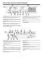
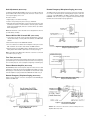
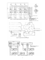
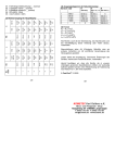
MCP35A
Master Control Panel
Installation & Use Manual
Specifications subject to change without notice.
© 2010 Bogen Communications, Inc.
All rights reserved. 54-5871-03E 1004
NOTICE: Every effort was made to ensure that the information in this guide was complete
and accurate at the time of printing. However, information is subject to change.
WARNING: To reduce the risk of Fire or Electric Shock, Do Not Expose this apparatus
to rain or moisture.
Apparatus shall not be exposed to dripping or splashing and no objects filled with liquids,
such as vases shall be placed on the apparatus.
WARNING: Only connect unit to AC mains outlet providing protective earthing connection.
NOTE: Mains plug is used as disconnect device from the mains and shall remain readily
accessible and operable.
CAUTION: DO NOT INSTALL OR PLACE THIS UNIT IN A BOOKCASE, BUILT-IN CABINET, OR IN
ANOTHER CONFINED SPACE. ENSURE THE UNIT IS WELL VENTILATED. TO PREVENT THE RISK
OF SHOCK OR FIRE HAZARD DUE TO OVERHEATING, ENSURE THAT CURTAINS AND ANY OTHER
MATERIALS DO NOT OBSTRUCT THE VENTILATION VENTS.
Always follow these basic safety precautions when installing and using the unit:
IMPORTANT SAFETY INSTRUCTIONS
1. Read these instructions.
2. Keep these instructions.
3. Heed all warnings.
4. Follow all instructions.
5. Do not use this apparatus near water.
6. Clean only with dry cloth.
7. Do not block any ventilation openings. Install in accordance with the manufacturer's instructions.
8. Do not install near any heat sources such as radiators, heat registers, stoves, or other apparatus
(including amplifiers) that produce heat.
9. Do not defeat the safety purpose of the polarized or grounding-type plug. A polarized plug has two
blades with one wider than the other. A grounding-type plug has two blades and a third grounding prong.
The wide blade, or the third prong, are provided for your safety. If the provided plug does not fit into your
outlet, consult an electrician for replacement of the obsolete outlet.
10. Protect the power cord from being walked on or pinched particularly at plugs, convenience receptacles,
and the point where they exit from the apparatus.
11. Only use attachments/accessories specified by the manufacturer.
12. Unplug this apparatus during lightning storms or when unused for long periods of time.
13. Refer all servicing to qualified service personnel. Servicing is required when the apparatus has been
damaged in any way, such as power-supply cord or plug is damaged, liquid has been spilled or objects
have fallen into the apparatus, the apparatus has been exposed to rain or moisture, does not operate
normally, or has been dropped.
CAUTION
RISK OF ELECTRIC SHOCK
DO NOT OPEN
CAUTION: TO PREVENT THE RISK OF ELECTRIC
SHOCK, DO NOT REMOVE ANY FRONT/BACK COVERS
OR PANELS. NO USER-SERVICEABLE PARTS INSIDE.
REFER SERVICING TO QUALIFIED PERSONNEL.
The lightning flash with arrowhead symbol, within an equilateral triangle,
is intended to alert the user to the presence of uninsulated "dangerous
voltage" within the product's enclosure that may be of sufficient
magnitude to constitute a risk of electric shock to persons.
The exclamation point within an equilateral triangle is intended to alert the
user to the presence of important operating and maintenance (servicing)
instructions.
Table of Contents
Introduction..................................................................................................................2
Unpacking ....................................................................................................................2
Front & Rear Panel Connection Diagrams ................................................................3
Installation....................................................................................................................4
Power and Grounding ................................................................................................4
Auxiliary Power Receptacle........................................................................................4
Line-Matching Transformers ......................................................................................4
Adjustments/Modifications ....................................................................................4-5
Gain Adjustments (Internal)........................................................................................4
Phantom Power (Internal) ..........................................................................................4
Telco Page/MIC 2 (Internal)........................................................................................4
Supervisory Tone Defeat (Internal) ............................................................................4
Gain Adjustments (Rear Panel)..................................................................................5
External MIC for MIC 1/Console MIC (Rear Panel) ..................................................5
Time Tone (Rear Panel) ............................................................................................5
External Booster Amplifier (Rear Panel) ....................................................................5
Remote Emergency Telephone Paging (Rear Panel) ................................................5
Remote Emergency Microphone Paging (Rear Panel) ..............................................5
Associated Equipment ............................................................................................6-7
SBA225 Room Selector Panel ..................................................................................6
SBA225 Wiring ..........................................................................................................6
SCR25A Call-In Module ............................................................................................6
SCR25A Installation ..................................................................................................6
TWK351 Option..........................................................................................................7
Staff Station Equipment ................................................................................................7
Call-Origination Switches ..........................................................................................7
Appendix ......................................................................................................................7
General Wiring ..........................................................................................................7
Call Switches and Speakers ........................................................................................8
Voice Call-In Option ......................................................................................................8
Call/Privacy Option........................................................................................................8
Technical Specifications ..........................................................................................10
Limited Warranty ......................................................................................................10
1
Introduction
The Bogen Model MCP35A Master Control Panel provides facilities for
instantaneous two-way communication and distribution of emergency
pages, background music or other program material to speaker-equipped
locations. The control panel has two built-in amplifiers. The intercom
amplifier, rated at 20 watts, features a frequency response shaped for
maximum intelligibility. The 35-watt program amplifier ensures that
program material and/or emergency announcements are clearly heard and
easily understood. Front panel step-by-step instructions and color-coded
lines make the MCP35A easy to operate.
The MCP35A control panel permits the user to:
Establish direct two-way communication between the control panel and
any speaker-equipped location via a room selector panel and the pressto-talk/release-to-listen push button, while maintaining simultaneous
distribution of program material to any other speaker-equipped location.
Make a program source selection by pressing the appropriately labeled
push button corresponding to the input from either of two microphones
(MIC 1, MIC 2) or one high-impedance program source (AUX), such as a
tuner or CD player.
Distribution of program material is accomplished by simple push-button
program selection, following the color-coded guidelines. Emergency
announcements to all locations take precedence over program distribution and are accomplished with a single (EMERGENCY PAGE) push
button selection.
Transmit a program selection or voice announcement simultaneously to all
speaker-equipped locations by pressing a program source push button
and the ALL ROOMS push button.
The program level can be monitored audibly (speaker) and visually (LED).
Inputs are provided for two Lo-Z balanced microphones, a Hi-Z unbalanced AUX program source (CD player/tuner, etc.), and telephone paging
accessories. Booster amplifier IN/OUT connections are also provided.
Provision are included to supply phantom power to microphones, distribute time signals to speakers, and make emergency all-call page
announcements from telephone or remote microphone. Rear-panelmounted and internal controls are provided to adjust the gain level of
individual inputs and to enable/disable system features.
Instantaneously transmit emergency messages to all speaker-equipped
locations by pressing the red EMERGENCY PAGE push button. The
emergency page feature overrides all system controls and functions and
transmits the emergency message at a predetermined level.
Distribute time signals to all speaker-equipped locations.
Provisions have been made for:
A console microphone (built-in) is normally used to communicate with a
station over the intercom channel, to send emergency page announcements to all stations, and may be used as program MIC 1. It is easily
defeated for external microphone applications. A built-in speaker is used
for intercom communication and for monitoring program material before
distribution. Provision is included to mute the speaker when the MIC 1
switch is pressed.
• Sounding a supervisory tone over any loudspeaker selected from
two-way communication. The tone alerts staff to a call and repeats at
regular intervals to prevent unauthorized monitoring from the control
panel.
• Staff call origination through the use of a call origination switch,
which causes a repetitive tone signal to sound at the control panel and
lights the annuniator lamp on the associated switch bank corresponding
to the calling location. The annunciator system functions until the call is
answered.
The MCP35A uses room selector panels to direct intercom or
program to selected staff stations. Panels are provided with switches to
place each room on a program channel, intercom channel, or off. Each
switch position on the panel includes an LED call-in annunciator.
• Voice-call origination to the control panel from any location equipped
with a voice call-in switch.
• Prevention of monitoring any location from the control panel when that
location is equipped with a Bogen Call/Privacy switch.
When a staff station is called from the control panel, a supervisory tone
alerts the staff member to the call. The tone repeats at regular intervals to
prevent unauthorized monitoring. Calls from staff stations may be initiated
through call-in switches and can include privacy control to positively prevent monitoring. Provision is included for voice call-in from stations
equipped with voice call-in switches.
• Transmission of page announcements from remote locations using the
Telco Page feature, which overrides all system functions except the
emergency page feature. The Telco Page may be used with the TELCO
PAGE input or the MIC 2 input (internally selected).
Unpacking
The MCP35A was carefully checked before leaving the factory.
Inspect the shipping carton and unit for damage caused by
improper handling. If damage is found, you must file a claim with the
transportation company that delivered the product.
2
Front & Rear Panel Connection Diagrams
1
9
Front
Panel
2
3
4
5
6
1. Console MIC - Used for intercom and emergency page functions. Normally
7
8
6. Program/Talk Level - LED Indicators: N (normal) lights green to indicate
proper signal level; P (peak) lights amber to indicate higher than normal signal
level; O (overload) lights red to indicate possible signal clip.
configured (via terminal link) as microphone 1. Provision has been made to optionally mute the monitor speaker when the MIC 1 switch is depressed.
2. Emergency Page - Red push button used to make announcements to all
speaker stations; overrides program distribution and room selector panel settings.
7. Program - Amber color knob used to adjust level of program material.
3. MIC 1, MIC 2, AUX - Push buttons used to select input source; choose from
speaker.
8. Monitor/Listen - Green color knob used to adjust volume level to front panel
MIC 1 (console or external microphone), MIC 2 (external microphone), or AUX,
as desired.
9. Front Panel Speaker - Used to monitor a program or to listen to a station
via the INTERCOM channel.
4. All Rooms - Push button used to distribute program to all speaker stations with
room selector panel switches set to the PROGRAM or OFF positions.
5. Press to Talk/Release to Listen - Push button used to communicate with
speaker station selected for intercom communication. Does not affect the distribution of program material to other stations.
7
6
5
4
3
2
1
Rear
Panel
11
10
9
8
1. Microphone Inputs - A terminal strip provides connection for two-low impedance balanced microphones. May (optionally) provide phantom power. The
console microphone is used as MIC 1; however, this feature may be disabled. Use
two-conductor shielded microphone cable.
6. Accessory - Mounting port for optional connector used to interface the Model
MCPB Control Panel.
7. Switch Bank - 9-pin connector accepts three audio pairs and three control
wires from room selector panels.
2. Voice Call-In - Connects parallel lines from station call-in switches with a
two- conductor shielded cable.
8. 25V BAL. INPUT - (From Booster) Stereo phone jack accepts input from a
booster amplifier. Refer to Figure 6.
3. AUX - Two phono jacks accept an unbalanced line-level input from CD player,
9. LINE OUT - Unbalanced line-level output to recorder or booster amplifier. The
tuner, etc.
output level is adjustable with the front panel LEVEL control.
4. Telco Page - Shorting the TELCO PAGE terminal to ground activates the
10. 12V DC & GND Terminals - For powering SCR25A and other accessories.
Telco page feature. The associated TELCO PAGE jack accepts an unbalanced
line input from Model WMT1A telephone interface device. This input has priority
over all other system functions except for the front-panel-mounted EMERGENCY
PAGE.
11. AUX Power - 840-watt, three-wire auxiliary power receptacle for accessory
equipment.
5. Time Clock - Shorting the TIME CLOCK Terminal to ground provides singlecircuit time signal capability.
3
Installation
Power and Grounding
The MCP35A Master Control Panel operates from a 120 volt, 60Hz AC
source and consumes approximately 100 watts. The AC line cord is terminated in a thee-prong plug, and should be plugged into a three-wire
grounded outlet providing nominal 120 volts, 60 Hz AC. It is important that
the control panel be grounded properly.
Auxiliary Power Receptacle
An 840-watt, three-wire grounded outlet is provided on the rear panel to
supply power to accessory equipment. Auxiliary equipment connected to
this outlet will be grounded, provided the MCP35A line cord has been properly grounded.
Line-Matching Transformers
The MCP35A Master Control Panel is designed for 25-volt constant-voltage
distribution systems. All system loudspeakers must be provided with linematching transformers. See Figure 1.
Figure 1 – Model T725 Transformer
Caution: Speakers and transformers must be properly matched with
respect to power requirements. The internal 35-watt amplifier of the MCP35A
should not be connected to a load of more than 75 loudspeakers, each
tapped at ½ watt (approx. 18 ohm). If a BPA60 booster amplifier is used,
the load should not exceed 125 loudspeakers, each tapped at ½ watt
(approx. 10 ohm). If loudspeakers are tapped at greater than ½ watt, either
the total number of loudspeakers must be reduced, or a more powerful
amplifier used.
Adjustments / Modifications
Supervisory Tone Defeat (Internal)
Caution: To avoid electric shock, be sure to disconnect AC Power Cord
before removing the cover of the amplifier unit.
Shunt J5 enables/disables the supervisory tone feature. Move the shunt
to the OFF position to disable the supervisory tone.
Warning: DO NOT perform any function requiring the removal of the
cover of the unit unless you are qualified to do so.
MIC 1 MIC 2
Gain Adjustments (Internal)
R10
Internal controls are provided to set the level of emergency page volume,
privacy tone volume, and time tone volume. These controls are factory
set; under normal circumstances no further adjustment is required.
Schematic/Circuit board designations: Emergency Page Volume, R39;
Supervisory Tone Volume, R74; Time Tone Volume, R75.
R20
AUX TELCO TALK LISTEN
R23
R41
R26
R52
REAR PANEL
ON
Phantom Power (Internal)
MIC 2
TELCO
J3
OFF
ON OFF
Phantom power may be supplied to MIC 1 and MIC 2 inputs to permit use
of phantom-powered condenser microphones. To enable, move shunts J1
(for MIC 1) and J2 (for MIC 2) to the ON position.
TELCO Page/MIC 2 (Internal)
J1
SUPERVISORY TONE
DEFEAT
J2
J5
R 39
R 74
J4
SUPERVISORY
TONE VOLUME
ON
Shunt J3 selects the TELCO PAGE input jack or the MIC 2 input terminals
for the telephone page function. Place the shunt at the MIC 2 position
when using the MIC 2 terminals for telephone paging applications.
OFF
ON
EMERGENCY
PAGE VOLUME
TIME TONE
VOLUME
OFF
FRONT PANEL
Figure 2 – Jumper Locations on MCP35A Card
4
R 75
Gain Adjustments (Rear Panel)
Remote Emergency Microphone Paging (Rear Panel)
Screwdriver-adjustable INPUT GAIN controls are accessible via the rear
panel for MIC 1, MIC 2, AUX, Tel Page, Talk, and Listen. Set the controls
so that signal clipping cannot occur.
The MIC 2 input may optionally be used in place of the Telco Page input
for use with a remote microphone (internal jumper). Figure 5 shows the
connection of the MBS1000A to the MIC 2 terminals. Refer to TELCO
PAGE/MIC 2 above for the proper configuration when the MIC 2 input
terminals are used for telephone page applications.
Proceed as follows:
1. Apply input(s) to the desired channel(s).
2. Set the corresponding front panel control(s) to maximum.
3. Adjust the appropriate Input Gain control (looking at the rear panel, turn
clockwise to increase or counterclockwise to decrease gain) so that the
red O (overload) LED lights; then turn counterclockwise only until the
LED is extinguished.
Note: Talk and Listen controls should be set for adequate intercom level
(not indicated by an LED).
External MIC for MIC 1/Console MIC (Rear Panel)
1. Locate and loosen the two screws securing the jumper link on the rear
chassis terminal strip connecting MIC 1 HI terminal to the CONS MIC
terminal.
2. Move the link away from the CONS MIC terminal.
3. Connect a balanced or unbalanced low-impedance microphone to the
MIC 1 terminals. Connect the cable shield to the GND terminal.
Figure 3 – Remote Emergency Page from
Telephone System Page Port
4. Move the shunt on J4 to the OFF position to disable the monitor speaker
muting feature when the MIC 1 push button is selected (see Fig. 2).
Note: J1 should be in the OFF position when the console mic is connected
to the MIC 1 input (see Fig. 2).
Time Tone (Rear Panel)
A tone signal sounds through all speakers when the time clock terminal is
grounded through a closure. (The tone may be used as a class change signal or for other purposes, such as a telephone night ringer or alarm signal.)
External Booster Amplifier (Rear Panel)
Model BPA60 provides increased power output. To install, connect a cable
terminated in a male phone plug from the MCP35A Line Out jack to the
Hi-Z input jack on the rear panel of the amplifier. Connect the 25V output
from the amplifier to input jack labeled 25V BAL INPUT. Refer to Fig. 6.
Remote Emergency Telephone Paging (Rear Panel)
Figures 3 and 4 show the connection of a telephone to the TELCO page
feature of the MCP35A.
Figure 4 – Remote Emergency Page using
Telephone Interface Device
Figure 6 – Booster Amplifier Output
Connection for MCP35A
Figure 5 – Remote Emergency Microphone
Page with MBS1000A
Caution: Do not insert or remove this connector while power is on;
amplifier failure may result.
5
Associated Equipment
SBA225 Room Selector Panel
SCR25A Call-In Module
Bogen Model SBA225 Room Selector Panels are capable of connecting
up to 25 speaker-equipped locations to a PROGRAM, INTERCOM
channel, or off. Each unit provides 25 lever-action, three-position,
four-pole selector switches with positive detents, and red LED indicators.
Caution: The installation of accessory equipment requires the removal of
protective covers; exposure of internal components presents an electrical
shock hazard. Accessory equipment should be installed by qualified
service personnel only.
Switch positions are graphically identified as PROGRAM A, OFF O, and
INTERCOM C, each with color-coded guidelines.
The Model SCR25A Call-In Module is an annunciator latching control bank
designed for use with Bogen SBA-Series Room Selector panels. The
SCR25A provides 25 silicon-controlled rectifiers and programmable
jumpers, and permits the use of either a momentary switch (such as the
Bogen Model CA17) or a telephone handset with fixed closure for call-in
from each staff location.
Each switch functions as follows:
PROGRAM / A – (Up position, amber color-code) Connects the speaker
station to the Program channel for distribution of program from microphone
or other program source. Overridden by Emergency Page, Telco Page,
and Time Signaling.
The SCR25A provides annunciator latching (as needed) to keep the
appropriate LED lamp illuminated until the call is acknowledged. Jumpers
are provided to select the method of call-in (momentary switch or fixed
closure handset).
OFF / O – (Center position, white color-code) Disconnects the speaker
station from the system; overridden by Emergency Page, Telco Page,
All Rooms, and Time Signaling.
The module is connected to the switch bank by a plug-in method and is
constructed of G-10 glass epoxy. Power supply is selectable by a jumper
and is taken from the switch bank or from an external power source.
Termination is via centerline connectors (Panduit or equivalent).
INTERCOM / C – (Down position, green color-code) Connects the
speaker station to the intercom channel. Overridden by Emergency Page,
Telco Page, and Time Signaling.
Note: To preserve intelligibility, only one station at a time should be
connected to the intercom channel.
SCR25A Installation
Connections
A white tabular strip, protected by a clear plastic snap-off cover, is
provided for labeling the station controlled by each selector switch. When
stations are identified by numbers, it is common practice to connect and
label the switches from left to right (viewed from the operatorʼs position),
starting at the uppermost panel.
1. Align the SCR25A module with the connector pins at the rear of the
SBA-Series panel and carefully press into place.
2. Make speaker and annunciator connections directly to the SCR25A
module as you would to the room selector panel.
Note: The pins that normally would not have been used on the SBAseries panel do not appear on the SCR25A panel.
When a station makes a call to the control panel, the corresponding LED
lights on the SBA panel and a repetitive tone alerts the operator to the call.
The LED remains on until the call is acknowledged by placing the appropriate switch to the C position.
Power Requirements
1. Jumper J26 in the upper right-hand corner of the SCR25A printed
circuit board must be in the Multi-Graphic position, as illustrated in the
diagram on the PC board.
Each room selector panel has provisions for accommodating the add-on
Bogen Model SCR25A Call-In Module, providing the circuits necessary
when using the call-origination switches which do not contain siliconcontrolled rectifiers.
2. Connect a wire from one of the pins marked P12, in the lower right-hand
corner, to the positive (+) terminal on an external 12V DC power supply.
Connect the negative (-) terminal on the power supply to ground on the
MCP35A. If more than one SCR25A is used, parallel P12 to each
SCR25A.
SBA225 Wiring
Across the rear of each switch bank is a row of male centerline terminals.
Each individual selector switch corresponds to the four terminals directly
behind it.
Note: If only one or two SCR25A modules are used, they can be powered
from the +12V terminal on the rear of the MCP35A.
Mode Selection
Note: The first three pins on the left (looking from the rear) and the last
pin on the right provide special functions and should not be connected to
speakers. Connectors used to connect speaker or handset wiring to the
SBA panel are standard parts stocked by many electronic parts distributors. We use Panduit .156 centerline connectors; however, equivalent
connectors are available by AMP or MOLEX. Wires are attached to
connectors using Panduit tool MRT-156F, or MCT with CTD-156F nose,
or equivalent.
For each channel using momentary switch contacts (no SCR) for call-in,
set the corresponding jumper (J1-J25) to the TOGGLE position (towards
the left, as looking at the rear).
For each channel to which a phone or SCR-equipped call-in switch (Bogen
CA10A or CA11A) is connected, set the corresponding jumper (J1-J25) to
the PHONE position (towards the right, as looking at the rear).
For clarity, two diagrams showing the relative positions of jumpers J1-J25
and J26 are screened onto the PC board.
Wire switch banks, as shown in Figure 12, using one female centerline
plug to terminate wires from the speaker and/or call switch. Connect the
shield to the ground terminal. This is the only place where speaker
cable shields should be grounded.
6
TWK351 Option
Appendix
The TWK351 option permits light call-in on 2-conductor shielded cable.
See Figure 7 for wiring diagram.
General Wiring
Where possible, locate the MCP35A centrally, relative to the rooms being
served, in order to minimize the length of speaker cables. Orient the unit
so that the operator, program director, or other parties are able to see the
controls at all times. Provide adequate lighting and ventilation. Do not
locate the unit close to heat sources (radiators, warm air ducts, etc.), or a
wall which would impede air flow through or around it.
Wires – Class II wiring may be used for all audio and annunciator lines.
Support cables to prevent sagging or strain. Keep wires clear of objects
that would subject them to heat, friction, or other abuse.
Use No. 22 AWG shielded pairs with insulated outer jacket for speaker lines.
Annunciator lines require a third wire, which usually is No. 22AWG insulated wire with clear insulation. The number and type of wire running from
each room to the control center are dependent upon the type of speaker
operation required. See Table 1.
Figure 7 – Wiring Diagram: TWK351 Option
Staff Station Equipment
Staff station equipment may include wall-or ceiling-mounted cone loudspeakers, or horn-type loudspeakers (used to ensure clear, intelligible
communication in areas with relatively high noise levels). Figure 9 shows
a wiring diagram for a loudspeaker. To initiate calls, locations are provided
with call-origination switches. The voice call-in option may be used when
stations are equipped with a customer-supplied DPDT momentary switch.
Call-Origination Switches
Voice Call-In Option – A customer-supplied double-pole, double throw,
Figure 8 – Wiring Diagram: Room Speaker with
Customer-Supplied Voice Call-In Switch
momentary contact switch maybe used to connect a staff station speaker
to the call-in line when the switch is actuated. See Figure 8.
CA10A and CA11A – These momentary, rocker-type Call Switches are
used to signal the control panel operator to establish communications
through a two-way speaker. The CA11A incorporates a privacy mode to
prevent monitoring. See Figure 10.
Figure 9 – Wiring Diagram: Loudspeaker (only)
A.
B.
Figure 10 – Wiring Diagram: A: Model CA10A; B: Model CA11A
7
Call Switches and Speakers
Call/Privacy Option
Flush-mounted switches require single-gang outlet boxes. Install outlet
boxes about four feet from the finished floor, in a location which will allow
personnel easy access to the switch for call-in and/or communicating via
the room speaker. Wall-mounted speakers should be installed at a
recommended height of 7-1/2 feet above the finished floor.
Figure 10 shows the room connections and the switch required for incorporating the optional privacy feature in the system.
Caution: To avoid electric shock, be sure to disconnect AC Power Cord
before removing the cover of the amplifier unit.
Warning: DO NOT perform any function requiring the removal of the
cover of the unit unless you are qualified to do so.
Grounds – Do not connect cable shields to earth grounds or convenient
metal objects. It is important to connect cable shields only as shown in the
wiring diagrams.
Voice Call-In Option
Figure 8 shows room connections and the customer-supplied switch
required for voice call-in. The wiring must be completed by connecting the
shielded pair from the switch to the terminal strip at the rear of the MCP35A
chassis. The polarity of the inner conductors is not critical, but make certain to connect this cable shield to the shield already connected to the terminal strip.
Note: Only one cable goes to the terminal strip. Usually, cables from all
room switches utilizing this function are connected by a common control
cable and one cable is run to the control panel. If this type of installation
is not practical, the control cables for two or more switches are run to the
control center and are connected in parallel at a junction box; a single
control cable is then run to the terminal strip at the rear of the MCP35A
chassis.
Table 1 – Cable Running Chart
Type of Call Switch or
Device used with Speaker
Wires from Room to Control Panel
No. 22 AWG Shielded
Wires from Room Switch to Room Speaker
No. 22 AWG
No. 22 AWG
Refer to Fig.
Voice Call-In, Non-Private
(Customer-supplied DPDT Switch)
2*
0
1
8
None (Loudspeaker)
1
0
0
9
Call Switch (CA10A)
1
1
1
10A
Call Switch (CA11A)
1
1
1
10B
* Alternative Method: Run two cables from room nearest the control panel and one cable from each remaining room.
Run one cable in a loop or branch circuit connecting all room switches.
8
Figure 11– Schematic Diagram, SBA225 Room Selector Panel
Figure 12– Typical Interconnection Diagram
Figure 13– Typical Wiring Diagram
9
Technical Specifications
Rated Output
Program
Intercom
Frequency Response
Program
Intercom
Distortion
35W RMS
20W RMS
+1,-3 dB from 80 Hz to 15 kHz
Shaped for maximum intelligibility
Less than 1% @ RPO and bandwidth
Inputs
Two Lo-Z balanced microphones; Hi-Z unbalanced AUX; TELCO PAGE; 25V BOOSTER
Output
25V balanced line
Controls
Front Panel
Rear Panel
Internal
Tone Specifications
Power Requirements
Dimensions
Weight
Optional Equipment:
Program Selection: MIC 1, MIC 2, AUX
Level: MONITOR/LISTEN, PROGRAM
Distribution: ALL ROOMS, EMERGENCY PAGE, PRESS TO TALK
Indicators: PROGRAM/TALK LEVEL
Input Gain: MIC 1, MIC 2, AUX, TELCO PAGE, TALK, LISTEN
Gain: Emergency Page, Supervisory Tone,Time Tone; Enable/Disable: MIC1/CONSOLE MIC,
MIC 2/TELCO PAGE, Phantom Power, Supervisory Tone
Time Tone: 750 Hz; Supervisory Tone: Repeating, 500 Hz; Call-in Tone: Repeating,
oscillates between 500 Hz and 750 Hz (Switching Frequency, 16 Hz)
120V, 60 Hz AC, 100W maximum
19" W x 3-1/2" H x 10" D, 2 Rack spaces
6 lb.
Model MCP-EXP Input Expander Panel, Model TWK351 adapter
Limited Warranty; Exclusion of Certain Damages
The Bogen MCP35A Master Control Panel is warranted to be free from defects in material and workmanship for two (2) years from the date of
sale to the original purchaser. Any part of the product covered by this warranty that, with normal installation and use,
becomes defective (as confirmed by Bogen upon inspection) during the applicable warranty period, will be repaired or replaced by Bogen, at
Bogenʼs option, provided the product is shipped insured and prepaid to: Bogen Factory Service Department, 50 Spring Street, Ramsey, NJ 07446,
USA. Repaired or replacement product will be returned to you freight prepaid. This warranty does not extend to any of our products that have
been subjected to abuse, misuse, improper storage, neglect, accident, improper installation or have been modified or repaired or altered in any
manner whatsoever, or where the serial number or date code has been removed or defaced.
THE FOREGOING LIMITED WARRANTY IS BOGENʼS SOLE AND EXCLUSIVE WARRANTY AND THE PURCHASERʼS SOLE AND
EXCLUSIVE REMEDY. BOGEN MAKES NO OTHER WARRANTIES OF ANY KIND, EITHER EXPRESS OR IMPLIED, AND ALL IMPLIED
WARRANTIES OF MERCHANTABILITY OR FITNESS FOR A PARTICULAR PURPOSE ARE HEREBY DISCLAIMED AND EXCLUDED TO
THE MAXIMUM EXTENT ALLOWABLE BY LAW. Bogen's liability arising out of the manufacture, sale or supplying of products or their use or
disposition, whether based upon warranty, contract, tort or otherwise, shall be limited to the price of the product. IN NO EVENT SHALL BOGEN
BE LIABLE FOR SPECIAL, INCIDENTAL OR CONSEQUENTIAL DAMAGES (INCLUDING, BUT NOT LIMITED TO, LOSS OF PROFITS,
LOSS OF DATA OR LOSS OF USE DAMAGES) ARISING OUT OF THE MANUFACTURE, SALE OR SUPPLYING OF PRODUCTS, EVEN IF
BOGEN HAS BEEN ADVISED OF THE POSSIBILITY OF SUCH DAMAGES OR LOSSES. Some States do not allow the exclusion or limitation of incidental or consequential damages, so the above limitation or exclusion may not apply to you. This warranty gives you specific legal rights,
and you may also have other rights which vary from State to State.
Products that are out of warranty will also be repaired by the Bogen Factory Service Department – same address as above or call 201-934-8500.
The parts and labor involved in these repairs are warranted for 90 days when repaired by the Bogen Factory Service Department. All shipping
charges in addition to parts and labor charges will be at the owner's expense. All returns require a Return Authorization number. For most
efficient warranty or repair service, please include a description of the failure.
12/2008
50 Spring Street, Ramsey, NJ 07446, U.S.A.
Tel. 201-934-8500 • Fax: 201-934-9832
www.bogen.com
10