1
222 HARTREY AVE., EVANSTON. IL. 60204 U.S.A.
@ AREA CODE312/866-2200
TWX: 910-231-0048
CABLE: SHUREMICRO
TELEX: 72.4381
I
DATA
SHEET
1
MODEL SR108 EXTENDED
RANGE SPEAKER SYSTEM
OPERATION AND SERVICE INSTRUCTIONS
the biamplification mode, the low-frequency section
accepts up to 200 watts and the high-frequency section
up to 100 watts of continuous program material. The
SR108 can be used either direct-coupled or with a
constant-voltage 70-volt line using a Shure A102A
Transformer.
The superior sound quality of the SR108 is achieved
through the use of six eight-inch low-frequency speakers, mounted in a linear array in a front-ported, hornloaded, bass reflex enclosure (fourth-order Butterworth
response) plus four high-frequency drivers coupled
to a single radial horn. The front-porting bass reflex
design of the enclosure provides extreme low-frequency enhancement, and horn-loading optimizes the
lower mid-range frequencies. A built-in series-type
passive crossover network is used with single-amplifier
inputs, and includes a four-position high-frequency
attenuator switch (LOUDSPEAKER OPERATION).
The LOUDSPEAKER OPERATION Switch is also
used to select between the single-amplifier, passive
crossover input and separate high- and low-frequency
inputs for operation in the biamplification mode. The
Shure Model SR106 Electronic Crossover provides
the proper low-frequency and high-frequency signal
splitting ahead of the power amplifiers for biamplified
operation.
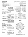
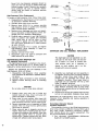
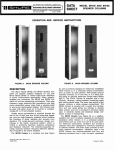
FIGURE A.
SR108 SPEAKER SYSTEM
DESCRIPTION
The Shure Model SR108 Extended Range Speaker
System is a rugged, heavy-duty, two-way speaker system designed primarily for high sound-pressure-level
reproduction of wide-frequency-range program material in sound reinforcement applications. The SR108
can be used with Shure Model SR105 or similar highpower amplifiers, in either a single-amplifier mode
(conventional full-range operation with passive crossover) or, with a Shure Model SR106 Electronic Crossover, in a biamplification mode of operation. The SR108
is also ideal for monitoring applications requiring wide
frequency response and high signal level capabilities.
When properly installed and connected, the SR108 will
provide outstanding performance in critical, high-level
applications due to its extremely wide frequency response, low distortion and smooth dispersion characteristics. The SR108 has a nominal impedance of 16
ohms and is designed to operate with up to 57 volts
rms input (200 watts continuous program material). In
Copyright 1977, Shure Brothers Inc.
27A1355 (QC)
The high-frequency section of the SR108 also contains automatic protection circuitry to avoid driver
damage at extremely high input levels. Additional
high-frequency driver protection is included in the biamplification mode to protect against damage from
low-frequency signals.
The SR108 is a portable unit, and is primarily designed for easy installation either indoors or in
a protected outdoor environment, such as under an
open pavilion. The system is supplied with a 15.2111
(50-foot), 18-gauge, rubber-jacketed connecting cable
with phone plugs. (A second connecting cable-Shure
No. RKC4, not supplied-is required for operation in
the biamplification mode.) The upper right rear section
of the SR108 contains a cable storage compartment.
The SR108 is constructed of 15.9 mm (5/8 in.) heavy
durable wood, coated with black, scuff-resistant, textured vinyl. All adhesives used in the SR108 are
moisture-resistant, and internal bracing is provided to
minimize vibration and maximize structural integrity.
The metal grille assembly is finished in durable gold
enamel. The radial horn is ruggedly constructed of
high-density, structural urethane foam, with fastening
hardware selected to provide strength and minimize
corrosion and visible wear. The SR108 is equipped
with an integral rear-panel handle and two heavy-duty,
hard-rubber wheels for mobility.
Printed i n U.S.A.
SPECIFICATIONS
Power Rating
(Program Material)
Single Amplifier lnput..200 watts max.
Low-Frequency lnput
(Biamplification Mode)..200 watts max.
High-Frequency lnput
(Biamplification Mode)..100 watts max.
Power Load for
Constant-Voltage
Operation .................... 39 watts
(25-volt input, 16 ohms)
50 watts
(70.7-volt input, through
optional A102A Transformer)
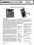
Impedance ....................3 6 ohms nominal for both conventional full-range and biamplified operation (see Figure B)
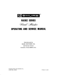
Frequency Response
....40
Hz - 15 kHz
(see Figure C)
Supplied Accessories ....One 15.2m (50-foot) heavy-duty
cable with phone plugs (RKC4)
Optional Accessories ....A102A 70-Volt Transformer
A50XC 15.2m (50-foot) Extension
Cable with male and female
phone plugs
RKC4 15.2m (50-foot) Heavy-Duty
Cable with male phone plugs
(for biamplified operation)
8 0
7 0
6 0
50
4 0
3 0
20
10
0
20
4 0
100
60
200
4 0 0 600
IK
2K
FREQUENCY
Crossover Frequency ....2600 Hz nominal
Sound Pressure
Level (SPL) ..................ElA rating: 54 dB at 9.2m (30
feet) from 1 milliwatt; equivalent to 102 dB at 1.2m (4 feet)
with I-watt input
Total Harmonic
Distortion ....................Less than 2% at 1 kHz and 10
kHz; less than 3% at 100 Hz
[measured at 1.8m (6 feet) and
106 dB SPL]
Phasing (Polarity)
Single Amplifier Input-.Positive voltage applied to phone
plug tip produces positive
sound pressure.
Biamplification Mode..Low Frequency: Positive voltage
applied to phone plug tip produces positive sound pressure.
High Frequency: Positive voltage
applied to phone plug tip produces negative sound pressure.
High-Frequency
Section ........................120" radial horn
4K
6K
IOK
FIGURE B.
IMPEDANCE CURVE
-
105
0
95
X
Y
TO Z" STERAMAN
u
51
LWDSPEAKER OPERATION S W W
75
/ I
20
40
I
I
W
I00
1111l1
200
400 W O
I
IK
FREQUENCY
2K
I lllllll
4K
BK
IOK
(HZ)
FIGURE C.
TYPICAL FREQUENCY RESPONSE
Horizontal Distribution ..140° (see Figure D)
Vertical Distribution ...... 90" (1 kHz -10 dB)
Operating Temperature..
- 7" to 43°C (20" to 110°F)
Storage Temperature .... - 29" to 71"C ( - 20" to 160°F)
Connectors ...................... Two parallel-wired phone jacks
for each input: conventional
full-range, low frequency and
high frequency
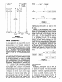
Overall Dimensions
(see Figure E) ..............1730 mm height x 495 mm width
x 517 mm depth (68% in. X
19% in. x 20% in.)
Weight ..........................-64.5
kg (142 Ib) incl. cable
Construction ....................15.9 mm (% in.) wood, black
vinyl finish, gold-painted metal
grille, anodized aluminum rear
panel rails, structural urethane
foam horn
2OK
(HZ)
I-
LEGEND
-----
...........
'?
I(:
8
KHz
1
FIGURE D.
TYPICAL HORIZONTAL POLAR PATTERN
I\U
20K
r""::
r.~?
CONENTICUM
FULL-RANGE
lpUr
n
PASSIVE
HIGH-FI1EWENCY
ATTENUATION
m g m E R
(4- 3/8IN.)
I
FULL RANGE
1
FULL-RANGE
BUW
LOI-FREOUENCI
WUT
O\
1
1
w
-0
8 m C n SHOWN N FULL RAW€ W K N
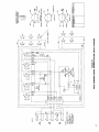
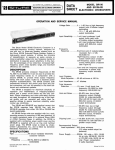
FIGURE F.
SR108 BLOCK DIAGRAM
high-frequency drivers which are wired in seriesparallel and provide a total nominal impedance of
16 ohms.
FIGURE E.
OVERALL DIMENSIONS
CIRCUIT DESCRIPTION
In conventional, full-range, single-amplifier operation, input signals from the power amplifier are connected to the SR108 through the uppermost set of
parallel-wired jacks to a series-type, passive LC
crossover network composed of two capacitors and
two inductors (see Figure F). The crossover provides
a 6 dB1octave rolloff for the low-frequency speakers
and an 18 dB/octave rolloff for the high-frequency
drivers. The inductance of the low-frequency speaker
voice coils provides an additional 6 dB1octave rolloff,
resulting in a total of 12 dB1octave low-frequency
rolloff.
Low-frequency signals are routed from the crossover directly to the six low-frequency speakers through
the rear-panel LOUDSPEAKER OPERATION Switch.
The low-frequency speakers are wired in two parallel
sets of three series-connected speakers, providing
a total nominal impedance of 16 ohms. High-frequency
signals are routed from the crossover through the
LOUDSPEAKER OPERATION Switch attenuator network which provides high-frequency level adjustments
of -4, -2, 0, and + 2 dB in the first four positions
of the switch. From the attenuator network, highfrequency signals enter a protection circuit designed
to prevent damage to the high-frequency drivers by
extremely high signal levels. Signal levels greater than
28 volts rms (approximately 50 watts) for longer than
15 milliseconds are sensed through a diode bridge,
causing a relay to engage high-wattage resistors
which decrease the high-level signals to the highfrequency drivers by approximately 7 dB. The circuitry automatically resets itself when the high-frequency signals drops below a safe threshold level.
The output of the protection circuitry feeds the four
Operation in the biamplification mode is accomplished by feeding separate high- and low-frequency
signals from an external 2600 Hz electronic crossover,
such as the Shure Model SR106 Electronic Crossover,
through separate high- and low-frequency power amplifiers, such as the Shure Model SR105 Power Amplifier, to the HlGH and LOW FREQUENCY input jacks
of the SR108 (see Figure G). With the rear-panel
LOUDSPEAKER OPERATION Switch in the BlAMP
position, the internal passive crossover of the SR108
is bypassed, and the low-frequency signals are routed
directly to the low-frequency speakers. High-frequency
signals also bypass the attenuator network, going directly from the LOUDSPEAKER OPERATION Switch
through the high-frequency protection circuit and a
12 dB1octave filter to the high-frequency drivers. The
filter serves to protect the drivers from low-frequency
transient signals produced by connecting input cables
to the power amplifier, turn-on thumps, or operating
errors.
SRlOB
SPEAKER SYSTEM
r-------1
HIGH
AUDIO CWSOLE
POWER
AMPLIFIER
I
HIGH-FREQUENCY
DRIVERS
I !'
ELECTRONIC
CROSSOVER
(2600HZ1
FIGURE G.
BIAMPLlFlED OPERATION
INSTALLATION
General
In planning a sound system using the SR108 Extended Range Speaker System, care must be taken
to observe the horizontal (140") and vertical (90")
sound distribution. Maximum coverage for sound reinforcement installations is generally obtained with
SR108's on each side of the sound source and as
far forward as possible. Assuming a single SR108
to either side of the sound source, the SR108's should
be positioned so that an imaginary line from the
center of each SR108 runs to the back row of the
audience area. For "clustered" SR108 installations
3
covering a wide area, each SR108 should be positioned so that its angle of coverage slightly overlaps
that of the SR108 next to it as their sound output
enters the audience area.
The problem of audience penetration may be likened
to illuminating a dark area with a floodlight: the object is to provide maximum area coverage (audience)
with the available floodlights (SR108's). At the same
time, care must be taken to avoid illuminating reflective surfaces. A blinding reflection (echo or "slapback") may be more of a problem than inadequate
coverage of the desired area.
Of the remaining common sound installation problems, acoustic feedback can usually be dealt with
by judicious placement of SR108's and microphones,
and/or the use of feedback filters on the audio console. Extreme background noise or acoustic absorption generally requires a greater volume level to
maintain an acceptable sound level. However, it must
be remembered that excessive sound levels may be
intolerable to that part of the audience nearest the
SR108's. In this case, or in those cases where the
architectural design leaves audience areas that are
not reached by the SR108's, the use of secondary or
auxiliary speaker systems should be considered.
Conventional Full-Range Direct-Coupled Operation
The SR108 is designed to accept program material
where the average power level reaches 200 watts on a
continuous basis. However, sine-wave or pink or white
noise signals of levels approaching 200 watts should
be avoided in that their duty cycle is much greater
than that of program material. Consequently, when
setting up or adjusting a sound system with SR108's,
avoid the use of high-level, continuous-type test signals. It should be pointed out that the various speaker
input jack pairs are for paralleling additional speakers
and not amplifiers.
CAUTION
Amplifier damage may result if two amplifiers are plugged into parallel jacks.
To insure safe operation of SR108's with program
material inputs, do not connect any input jack to
an amplifier or amplifiers with output capabilities
greater than shown in Figure H.
70-Volt Operation
The SR108 Speaker System may be used on a constant-voltage, 70.7-volt line by using a 70-volt transformer such as the Shure Model A102A. This transformer provides power taps of 50, 25, 12, and 6
watts and speaker impedance taps of 8 or 16 ohms
(see Figure J).
In the biamplification mode, connect A102A transformers using one transformer for the high-frequency
input and one for the low-frequency input. Connect the
low-frequency amplifier 70-volt line to the power tap
of one A102A transformer, choosing the tap that produces the desired power level. Connect the high-frequency amplifier 70-volt line to the power tap of the
other transfomer offering the most suitable balance
of high- to low-frequency sound. First try the highfrequency power tap that is one-half the power of
the low-frequency tap. Listen to program material
f0
--
.
TO
-
CAUTION
DO NOT CONNECT LOUDSPEAKER
A POWER AMPLIFIER
WITH AN OUTPUT POWER OR VOLTAGE RATING GREATER
THAN THE VALUES INDICATED BELOW. SEE INSTRUCTION
MANUAL FOR ADDITIONAL INFORMATION.
3
AMPLIFIER OUTPUT SHOULD NOT EXCEED
CONTINUOUS CONTINUOUS CONTINUOUS
POWER
POWER
POWER
TO 16 OHMS TO 8 OHMS TO 4 OHMS
INPUT
CONTINUOUS
OUTPUT
VOLTAGE
PEAK
HIGH FREO
ElAMP
100
WATTS
200
WATTS
400
WATTS
40
VOLTS RMS
65
VOLTS
'
";,As
400
WATTS
800
WATTS
57
VOLTS RMS
92
VOLTS
FULL RANGE
'OW FREa
BIAMP
LOUDSPEAKER CONNECTION
-
I
I
I
PARALLEL
I
_
I
16 OHMS
1
I
-
CONVENTIONAL FULL-RANGE OPERATION
I
PARALLEL
II
I I LOW
FREO SECTION BIAMP OPERATION
16 OHMS
I X l E R N A L LOW P 1 S S CROSSOVER NETWORK
REOUlRED ( 1 6 0 0 H Z bOB/OCTAVE)
1)( 1
HIGH FREO SECTION BIAMP OPERATION
16 OHMS
EXTERNAL HIGH PASS CROS1016. N11WORK
l l O U l R l D i 1 6 0 0 H Z I1OB/OCTAVBl
WARNING
0
THIS SPEAKER CAN PRODUCE SOUND PRESSURE LEVELS WHICH MAY
CAUSE PERMANENT HEARING DAMAGE AFTER PROLONGED EXPOSURE.
0
J
FIGURE H.
SPEAKER INPUTS
through the sound system and adjust the high-frequency power tap if a different high-frequency/lowfrequency balance is desired.
Phasing (Polarity)
The SR108 is phase-wired for conventional, fullrange operation as follows: A positive voltage applied
to the CONVENTIONAL FULL-RANGE OPERATION
lnput Jack tips will produce a positive sound pressure below 2600 Hz and a negative sound pressure
above 2600 Hz. In biamplified operation, a positive
voltage applied to the LOW FREQ/BIAMP OPERATION lnput Jack tips produces a positive sound pressure, and a positive voltage applied to the HlGH
FREQ/BIAMP OPERATION lnput Jack tips produces
a negative sound pressure. This conforms to the
requirements of the SR108 internal passive crossover network, which provides the proper phase relationships at the crossover frequency.
When using the SR108 in biarnplified operation
with an external active electronic crossover network
and separate power amplifiers, the following considerations should be given to phasing: When using a
Shure Model SR106 Electronic Crossover and identical power amplifiers (Shure SR105 or equivalent) to
power an SR108, the phasing is correct. Dissimilar
high- and low-frequency power amplifiers may be
A102A
POWER
"HOT"
-I
02=w
0 12W
70.7 V LlHE
GROUND
SYSTEM
0 COM
5 0 - 6 WATTS
FIGURE J.
70-VOLT OPERATION
used as long as all low-frequency sections are in
phase with one another and all high-frequency sections
are in phase with one another. A potential problem
exists only when there is a phase reversal between
the high- or low-frequency sections of the speaker
systems in use. To check for a possible out-of-phase
condition, the following listening test should be performed on both high- and low-frequency sections
of the SR108's. The test should be made feeding two
SR108's at a time (using one SR108 as a phase reference) with the same program material (vocal material, or pink noise). Connect the SR106, power amplifiers, SR108's, and program input equipment.
CAUTION
Do not interchange high- and low-frequency
speaker cables. Damage to high-frequency
drivers from high-level, low-frequency signals may result.
Turn on the sound system and adjust for a moderate
level. Disconnect the high-frequency driver input cables. Stand approximately mid-way between the two
SR108's and listen to the program material while
reversing the "hot" and common leads to one of
the low-frequency speaker sections. (This may be
accomplished by wire-reversing or by a simple crosswired, double-pole, double-throw switch.) Use the
connection that gives a localized sound, centered between the SR108's; this is the correct phase connection. A diffuse, directionless sound indicates improper
phasing.
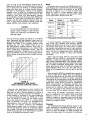
AWLlCEI-TO-SPEIKER
AMPLIFER-TO-SPEAKER
DISTANCE
VEETl
DISTANCE IYLTLRSI
FIGURE K.
RECOMMENDED WIRE GAUGE:
DIRECT-COUPLED AMPLIFIER OUTPUT
Reconnect the high-frequency driver sections and
disconnect the low-frequency sections. Perform the
same test as above. Correct phasing will provide a
localized sound, centered between the SR108's; incorrect phasing is indicated by the sound appearing
to come predominantly from one SR108 and to shift
from one SR108 to another as the listener moves
around the audience area. NOTE: In a mixed system
(both conventional full range and biamplified) the
high-frequency driver sections are normally out of
phase with one another. Therefore, the biamplified
high-frequency signals must be reversed to assure
that the high-frequency drivers of all speaker systems
are in phase. This may be accomplished with a Shure
A15PR Phase Reverser at the high-frequency amplifier
input or the SR106 high-frequency output.
Wiring
The cables used to connect the SR108 should be at
least 18-gauge and rubber-jacketed. Determine the approximate distance from the amplifier to the SR108
and refer to Figures K or L to find the proper wire
gauge for direct or 70-volt amplifier output (with
A102A transformer) operation. Recommended cables
for the sizes listed in Figure K and L are:
Gauge
Belden #
AWG 18
8460, 8461,
9720, 8452
AWG 16
AWG 14
I
1
1I
y28471,
8473
1
AWG 12
1
Area (mm2)*
0.8
1
1
1.3
2.1
1
8477
3.3
I
5.3
AWG 10
*Cross-section of American Wire Gauge (AWG)
To avoid frequency cancellations, poor coverage,
dead zones, etc., resulting from improper speaker
phasing, the SR108's must be wired in proper polarity.
The cables listed above are color-coded to ensure
that identical connections are used for each amplifierSR108 hookup. Note that even common 18-gauge lamp
cord ("zip cord") is phase-coded with a ribbed outer
jacket, color-coded threads, or tinned and untinned
conductors.
When using the 15.2m (50-foot), heavy-duty cable
supplied with the SR108 in conventional full-range
operation, connect the right-angle plug to a phone
jack marked CONVENTIONAL FULL-RANGE OPERATION and twist the cable downward behind the locking
bar to prevent accidental disconnection. The other
phone jack may be used for additional, parallel-connected SR108's. When not in use, the cable may be
stored in the compartment at the top right of the rear
panel.
When wiring the SR108 for biamplification operation,
a second cable (Shure RKC4) must be obtained to
provide connections to both the HIGH and LOW FREQ
input phone jacks. The same wire gauge constraints
listed above for conventional full range operation apply
to operation in the biamplification mode. Two separate
cables (four wires) should be used for amplifier-toSR108 interconnection in biamplified operation. Note
that the SR108 high- and low-frequency inputs are
isolated and a three-wire cable could be used; however, the wire gauge of the common wire should be
one size larger than the gauge indicated in Figure K.
When wiring the SR108's consideration should be
given to positioning of the cables. While most local
electrical codes do not require locating speaker
cables in conduits or raceways, make sure that cable
placement minimizes traffic interference and physical
abuse to the cable or SR108.
Placement
The SR108 Extended Range Speaker System is primarily designed for free-standing operation. In positioning for optimum sound coverage, care must be
taken to locate the SR108's on stable surfaces and
away from areas where the movement of performers,
FIGURE L.
RECOMMENDED WIRE GAUGE: 70-VOLT AMPLIFIER OUTPUT (USING A102A TRANSFORMER)
audience, curtains or stage sets may cause inadvertent
movement (tipping or sliding). If potentially hazardous
locations cannot be avoided, the SR108's should be
secured with rope, cable or strapping to maintain
their physical positions and prevent accidents.
If it becomes necessary to elevate the SR108 for
proper sound coverage, adequate support for elevations up to about three feet can usually be obtained
using a sturdy table or bench. It should be established
in advance that the surface is capable of supporting
the 64.5 kg (142 Ib) weight of the SR108.
For elevations greater than three feet, it is important
to note that the SR108 is not designed for simple chain,
cable or bracket mounting. A heavy-duty shelf-type
mounting capable of supporting the weight of the
SR108 should be devised for wall-mounted locations.
Shelf and supporting materials, hardware and wall
structure must be carefully considered when planning
this type of mounting. The building contractor, architect or engineer should be consulted to provide building construction information and verify the safety of
the proposed mounting plan. Whenever possible, a
backplate should be used on the opposite side of
the mounting wall to secure the mounting hardware,
and some means of preventing possible sliding off the
shelf must be devised.
WARNING
Under no circumstances should an SR108
be hung by eyebolts and chains or cables
attached to the sides, rear, handle or top.
The SR108 enclosure is not designed to
withstand the stresses incurred in this type
of mounting.
or cables. As in wall-mounting, careful consideration
must be given to the materials, hardware and chain
or cable mounting surface. The cable or chains must
be located at each corner of the platform, and should
be capable of supporting four times the total weight
of the SR108 plus the platform.
If the SR108 is to be used on a constant-voltage
system, a Shure A102A 70-Volt Transformer must be
connected between each amplifier and SR108. If the
A102A Transformer is used, it should be located as
close to the SR108 as possible. If mounted to the rear
of the SR108, the transformer adds approximately 82
mm (3Y4 in.) in depth and 2.95 kg (6 Ib) in weight to
the SR108.
Checking Sound Coverage
When the SR108's, amplifiers and other equipment
have been installed and connected, apply a fairly constant level signal to the system (preferably a uniform
level, full frequency range program material) and walk
around the audience area. Listen for a smooth, even
output from the SR108's with minimal differences in
volume and tone, and no distortion or "dead spots."
A dead spot-for
audio purposes, an audience area
where no sound is heard, or where the sound level
is appreciably lower than the rest of the audience
area-may
mean that the SR108's are not covering
that area; or that the SR108 speaker wires are connected out-of-phase. Proper phasing (polarity) may be
readily determined by checking the connections to
the phone jacks on each SR108 to make sure they
are the same; inadequate coverage generally requires
repositioning the SR108's.
Should a dead area be encountered, it should be
carefully examined to determine if the problem can
be corrected without resorting to auxiliary speakers.
BlAMPLlFlCATlON
If suspended mounting, using chains or cables attached to beams or girders, is an absolute necessity,
a platform must be devised which will be capable of
both supporting the SR108 and retaining the chains
6
The data in this section relates only to the use of
the SR108 in the biamplified mode. Some portions of
data in preceding sections are repeated here to provide a comprehensive section on biamplification.
Circuit Description
Biamplified operation is accomplished by feeding
separate high- and low-frequency signals from an
external 2600 Hz active crossover network, such as
the Shure Model SR106 Electronic Crossover, through
separate high- and low-f requency power amplifiers,
such as the Shure Model SR105 Power Amplifier, to
the HlGH and LOW FREQ lnput Jacks of the SR108
(see Figure G). With the rear-panel LOUDSPEAKER
OPERATION Switch in the BIAMP position, the internal
passive crossover of the SR108 is bypassed, with the
low-frequency signals routed directly to the low-frequency speakers (see Figure F). High-frequency signals also bypass the internal passive crossover and
bypass the attenuator network, going directly from
the LOUDSPEAKER OPERATION Switch through the
high-frequency protection circuit to the high-frequency
drivers. In the biamplified mode, the high-frequency
protection circuit includes an overvoltage attenuator
network, and a capacitor-inductor, low-frequency rolloff network which protects the high-frequency drivers
from low-frequency transient signals produced by connecting input cables to the power amplifier, turn-on
thumps, or operating errors.
Direct-Coupled Operation
To avoid damage to speakers or drivers when setting up or adjusting a sound system using the SR108,
avoid the use of high-level, continuous-type test signals. Program-type material up to 200 watts may be
used without special precautions.
For optimum safe operation in the biamplified mode,
do not connect the HlGH or LOW FREQ lnput Jacks
of the SR108 to amplifiers with output capabilities
exceeding those shown in Figure H.
CAUTION
Do not interchange the high- and low-frequency speaker cables. Damage to the highfrequency drivers due to high-level, lowfrequency signals may result.
,
70-Volt Operation
For biamplified operation from a constant-voltage,
70-volt line, connect Shure A102A 70-Volt Transformers
between the power amplifiers and SR108 as follows:
1. For low-frequency input power levels from 6
to 50 watts connect the "hot" side of the 70-volt
line to the appropriate tap on the A102A Transformer (50-6W) (Figure J). Connect the ground
side of the 70-volt line to the COM power tap of
the A102A, and the COM impedance tap of the
A102A to the negative (phone plug sleeve) terminal of the SR108 LOW FREQ lnput Jack. Connect the 16-ohm impedance tap of the A102A
to the positive (phone plug tip) terminal of the
SR108 LOW FREQ lnput Jack.
2. For the high-frequency 70-volt input (any power
level up to 50 watts), connect the "hot" side
of the 70-volt line to the power tap of a second
A102A Transformer offering the most suitable
balance of high- to low-frequency sound. First
try the high-frequency power tap that is onehalf the power of the low-frequency tap. Connect the ground side of the 70-volt line to the
A102A COM power tap. Connect the A102A 16-
ohm impedance tap to the positive (phone plug
tip) terminal ot the SR108 HlGH FREQ lnput
Jack, and the A102A COM impedance tap to the
negative (phone plug sleeve) terminal of the
SR108 HlGH FREQ lnput Jack. Listen to program material through the sound system and
adjust the high-frequency power tap if a different high-frequency/low-frequency balance is
desired.
Phasing (Polarity)
The SR108 is phase-wired for biamplified operation
as follows: A positive voltage applied to a LOW
FREQ lnput Jack tip produces a positive sound pressure, and a positive voltage applied to a HlGH FREQ
lnput Jack tip produces a negative sound pressure.
This conforms to the requirements of the internal
passive crossover network, and to the design of most
two-way speaker systems.
When using the SR108 with an external active
electronic crossover network and separate power amplifiers, the following considerations should be given
to phasing: When a Shure Model SR106 Electronic
Crossover and identical high- and low-frequency power
amplifiers (Shure Model SR105 or equivalent) are used,
the phasing is correct. A different crossover network
or dissimilar high- and low-frequency power amplifiers
may be used as long as all low-frequency sections
are in phase with one another and all high-frequency
sections are in phase with one another. A potential
problem exists only when there is a phase reversal
between the high- or low-frequency sections of the
speaker systems in use. To check for possible outof-phase condition, the following listening test should
be performed on both high- and low-frequency sections of the SR108's. The test should be made feeding two SR108's at a time (using one SR108 as a phase
reference) with the same program material (vocal material, or pink noise). After connecting the equipment,
turn on the sound system and adjust for a moderate
level. Disconnect the high-frequency driver input ca-,
bles. Stand approximately mid-way between the two
SR108's and listen to the program material while
reversing the "hot" and common leads to one of the
low-frequency speaker sections. (This may be accomplished by wire-reversing or by a simple cross-wired,
double-pole, double-throw switch.) Use the connection
that gives a localized sound, centered between the
SR108's; this is the correct phase connection. A diffuse, directionless sound indicates improper phasing.
Reconnect the high-frequency driver sections, disconnect the low-frequency sections, and perform the
same test as above. Correct phasing will provide a
localized sound, centered between the SR108's; incorrect phasing is indicated by the sound appearing
to come predominantly from one SR108, and to shift
from one SR108 to another as the listener moves
around the audience area. NOTE: In a mixed system
(both conventional full range and biamplified) the highfrequency driver sections are normally out of phase
with one another. Therefore, the biamplified high-frequency signals must be reversed to assure that the
high-frequency drivers of all SR108's are in phase.
Wiring
For biamplified operation, a second cable must be
obtained (Shure RKC4 or equivalent). When using
other cables, or when using extension cables, the
wire gauge constraints shown in Figures K and L
apply. As in conventional full-range operation, the
second HIGH and LOW FREQ lnput Jacks may be
used for additional, parallel-connected biamplified
SR108's.
BASIC OPERATING HINTS
Should any difficulty be encountered in SR108 operation, the problem may often be traced to some
simple source such as an er.ror in interconnection.
The following is offered as a basic guide to problems
of this sort.
Symptom: SR108 is "dead" (no output)
Check:
1. Check inputs and outputs of all equipment driving SR108.
2. Check interconnecting cables and connectors.
3. Check to see that LOUDSPEAKER OPERATION Switch position corresponds to
desired operating mode.
Symptom: Poor or no high-frequency output (normal
low-frequency output)
1. Check setting of LOUDSPEAKER OPERCheck:
ATION Switch.
2. If symptom appears only when LOUDSPEAKER OPERATION Switch is in BIAMP position, check output of equipment
driving high-frequency drivers.
3. Check high-frequency response of program material.
Symptom: Poor or no low-frequency output (normal
high-frequency output)
Check:
1. If symptom appears only when LOUDSPEAKER OPERATION Switch is in BIAMP position, check output of equipment
driving low-frequency speakers.
2. Check low-frequency response of program material.
SERVICE INSTRUCTIONS
Speaker Servicing
1. To measure dc resistance of high-frequency
driver assembly (LOUDSPEAKER SWITCH in any
position), first remove speaker cables. Remove
10 Phillips head screws securing upper rear
panel to enclosure. Remove panel and disconnect wiring harness (PI) from its socket (J7)
on printed circuit board (see Figure M). Unsolder high-frequency driver leads from inductor
L2 and measure dc resistance of high-frequency
driver assembly (LS7-LS10). Total dc resistance of assembly should be between 12.5 and
14.5 ohms.
To measure dc resistance of each high-frequency driver (LS7-LSlO), remove five bolts securing high-frequency driver assembly support
bracket (318" and 9/16" socket wrench may be
used) and remove bracket. Do not permit highfrequency driver assembly to drop when bracket
is removed. Carefully withdraw high-frequency
driver assembly (drivers and throat adapter assembly) from compartment. Disconnect one lead
between the four high-frequency drivers. Measure resistance of each high-frequency driver
voice coil. Each driver should measure between
12.5 and 14.5 ohms. Replace any defective
drivers as described in High-Frequency Driver
Replacement.
2. If above tests do not locate defective high-frequency driver, check for voice coil rubbing or
binding by driving each driver with a test signal
(4V max.) from a sweep oscillator and amplifier
covering the frequency range from 2600 to
10,000 Hz.
WARNING
Sound pressure levels generated by this
test may be damaging to your hearing. Aim
drivers away from listeners and toward
sound-absorbent material (curtains, blanket,
etc.). Carefully adjust test signal amplitude
to avoid unnecessarily high sound pressure
levels for prolonged periods.
Sound from high-f requency drivers should be
clean and free from buzzes or rattles which may
indicate driver failure. Replace any defective
drivers as described in High-Frequency Driver
Replacement.
3. To measure dc resistance of low-frequency
speakers, connect an ohmmeter between tip
and sleeve connections of FULL-RANGE lnput
Jacks J1 or J2 (LOUDSPEAKER OPERATION
Switch in -4, -2, 0 or +2 position), or between tip and sleeve connections of LOW FREQ/
BlAMP OPERATION lnput Jacks J3 or J4 (LOUDSPEAKER OPERATION Switch in BlAMP position). The FULL-RANGE resistance reading
should be between 11.25 and 13.35 ohms, and
the BlAMP reading should be between 11.25
and 12.75 ohms. Readings outside these limits
indicate possible low-frequency speaker failure.
To measure dc resistance of each low-frequency
speaker (LS1-LSG), remove 26 Phillips head
screws securing lower rear panel to enclosure.
Remove rear panel and rest it on floor, taking
care not to stress input jack wiring. Using ohmmeter, measure resistance of each low-frequency
speaker coil. A clicking sound will be made by
a "good" speaker when ohmmeter is connected
or disconnected. Each low-frequency speaker
should measure between 7.5 and 8.5 ohms with
speaker leads disconnected. Replace any speakers found defective.
4. If above tests do not locate defective low-frequency speaker, check for voice coil rubbing or
binding by first disconnecting lead between two
top low-frequency speakers. Set sweep oscillator and amplifier to produce test signal (8V max.)
and sweep each speaker over the frequency
range of 50 to 2600 Hz.
WARNING
Sound pressure levels generated by this
test may be damaging to your hearing. Aim
drivers away from listeners and toward
sound-absorbent material (curtains, blanket,
etc.). Carefully adjust test signal amp1itude
to avoid unnecessarily high sound pressure
levels for prolonged periods.
Sound from low-frequency speakers should be
clean and free from buzzes or rattles which may
indicate speaker failure. Replace any speakers
found defective. Be sure to resolder disconnected leads and fasten all hardware securely
to avoid rattles.
High-Frequency Driver Replacement
To replace a high-frequency driver, follow these steps:
1. Disassemble the high-frequency driver assembly
as described in Speaker Servicing.
2. Unsolder leads from driver terminals.
3. Remove three 6-32 x 1% in. screws securing
high-frequency drivers to gasket and mounting
plate of throat adapter assembly.
4. Replace driver diaphragm and voice coil assembly as described in High-Frequency Driver Diaphragm and Coil Assembly Replacement.
5. Carefully place repaired or new high-frequency
driver in position over gasket and mounting
plate, taking care to line up holes in driver
over holes in gasket and mounting plate. Be
sure that driver terminals are in same position
as when removed.
6. Replace three 6-32 x 1% in. screws, and tighten
high-frequency driver assembly in upper enclosure compartment.
7. Resolder removed driver leads.
8. Reassemble upper rear panel to enclosure and
fasten securely to avoid rattles.
High-Frequency Driver Diaphragm and
Coil Assembly Replacement
The high-frequency driver is attached to the mounting plate with three 6-32 X 1% in. screws. Refer to
Figure N for further identification of driver components.
Replace the diaphragm and coil assembly in the
high-frequency driver as follows:
1. Disassemble high-frequency driver assembly
from enclosure as described in Speaker Servicing above.
2. Unsolder leads connected to driver terminals.
3. Remove screws securing driver to mounting
plate.
CAUTION
Do not allow driver to drop when removed.
4. Prepare clean work area, free of drafts and
metallic dust and chips. Cover work area with
clean kraft paper or newspaper.
5. Place driver on work surface. With three 6-32
X 1% in. screws securing driver to mounting
plate previously removed, remove'phasing plug.
6. Remove diaphragm and coil assembly by lifting
upward. This is a snug fit and a gentle prying
force may be required.
7. Clean voice-coil gap in magnetic structure as
follows: Insert strip of masking tape into voicecoil gap with adhesive side outward. Draw tape
around gap several times to provide good
wiping action. Repeat process with new piece
of tape with adhesive side facing inward.
MOUNTING PLATE
ADAPTER ASSEMBLY 1
GASKET-
DIAPHRAGM AND
COlL ASSEMBLY
!
CLEARANCE
HOLES 161*
1
I
VOICE-COIL
LOCATOR
GAP
PINS 131
CLEARANCE HOLES
MAGNETIC
STRUCTURE
131
I
FIGURE N.
DIAPHRAGM AND COlL ASSEMBLY REPLACEMENT
CAUTION
The diaphragm and coil assembly is a delicate part. Do not touch voice coil and bobbin, or allow it to come in contact with
work surface, tools, etc. If assembly is
placed on work surface, rest it on diaphragm with voice coil upward.
8. Assemble new diaphragm and coil assembly to
to magnetic structure with coil facing magnetic
structure. Locate three small holes in diaphragm and coil assembly over locator pins
in magnetic structure. Three large holes in
diaphragm and coil assembly will line up with
holes in magnetic structure.
9. Assemble driver and phasing plug to mounting
plate. Position mounting holes so that solder
terminals are outward and do not interfere with
adjacent drivers.
10. Replace three screws and tighten them securely
but do not over-tighten. Resolder driver leads.
Reassemble the high-frequency driver into the highfrequency driver assembly and replace assembly in
speaker enclosure.
Overvoltage Attenuator Network
Threshold Adjustment
The protection circuitry of the SR108 high-frequency
driver array contains a 2000-ohm rheostat (R10) which
may under certain conditions (component replacement, extreme shock, etc.) require readjustment. This
may be accomplished as follows.
1. Turn rear-panel LOUDSPEAKER OPERATION
Switch (Sl) to BlAMP position.
2. Remove upper rear panel as described in Speaker Servicing above.
3. Unsolder high-frequency driver assembly leads
(black and green) from inductor assembly L2,
and place a dummy load (16 ohms, 50 watts
minimum) across L2.
4. Connect an ac voltmeter (Simpson 260 or equivalent) across dummy load.
5. Apply a 5 kHz ac voltage from a power amplifier
across one HlGH FREQ/BIAMP OPERATION Input Jack (J5 or J6). Slowly increase voltage
until 28 Vac is reached. Relay K1 should open,
as indicated by ac voltmeter reading suddenly
dropping to approximately 13 Vac. If it does
not, adjust rheostat R10 until relay K1 operates
as input voltage reaches 28 Vac. Remove input
voltage to release relay.
6. Remove ac voltage, disconnect dummy load and
voltmeter, and resolder high-frequency driver
leads. Replace rear panel and tighten all screws
securely to avoid rattles.
Radial Horn Replacement
To replace the SR108 high-frequency radial horn,
follow these stem:
1. Remove 10 #8 Phillips head screws securing
horn to front of enclosure.
2. Lift horn outward from front of enclosure, insert
new horn, and replace 10 Phillips head screws.
3. Replace foam screen in horn throat, apply PLIOBOND (or equivalent) cement around edges to
hold it in place. Make sure all hardware is tightly
fastened to avoid rattles.
Grille Assembly Replacement
To remove and replace the SR108 front-panel grille
assembly, follow these steps:
1. With SR108 lying flat on a firm surface, use a
short length of wood (2 in. X 4 in. is recommended) to apply firm, steady pressure at center of grille approximately one-third distance
from top.
2. As grille is pushed back, edges will appear in
left and right slots. Use a screwdriver or knife
to gently pry edges of grille up over edge of
slot on either left or right side.
3. Begin removing grille assembly from top, taking
care not to scratch enclosure with edge of grille.
2
WARNING
Grille assembly is under tension and effectively presents a spring-loaded rough edge
as it is removed. Take care not to handle
assembly at edges during removal.
4. As grille edge near top comes free, move hand
applying pressure and screwdriver edge downward to free remainder of grille.
5. Replace new grille assembly by centering it in
enclosure, and applying pressure at center until
grille assembly "pops" into slots.
Wheel Assembly Replacement
To replace a wheel or other parts of the SR108
wheel assembly, follow these steps (see Figure R):
1. Place SR108 face downward on flat surface and
remove lower rear panel as described in Speaker Servicing.
2. While holding 3/4 in. locknut with a socket
wrench, insert a %I in. Allen wrench in wheel
assembly capscrew and unscrew capscrew from
the assembly.
3. With locknut, flat washer and capscrew removed,
wheel and bushings may now be removed.
4. When reassembling wheel assembly, be sure
to replace flat washer before tightening locknut.
Tighten capscrew and locknut firmly.
5. Install back panel and tighten securely to avoid
rattles.
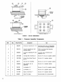
Model RKC149 Crossover Assembly
A complete crossover assembly may be obtained
from Shure Brothers Inc. as Model RKC149. This assembly provides complete facilities for high- and
low-frequency signal separation, and overvoltage protection. A general description of the crossover assembly is included in the CIRCUIT DESCRIPTION
section, and biamplified operation is described in the
BlAMPLlFlCATlON section.
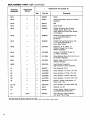
The Model RKC149 consists of the components listed
in Table 1 (refer to Figures M and P, and the Replacement Parts List).
The LOUDSPEAKER OPERATION switch (Sl) contains the following settings:
Position 1 (full CCW): FULL RANGE - 4 dB
Position 2:
FULL RANGE - 2 dB
Position 3:
FULL RANGE 0 dB
Position 4:
FULL RANGE + 2 dB
Position 5 (full CW):
BlAMPLlFlED
Connector P I is a nine-pin connector in which eight
pins are connected as follows (see Figures M and P):
Pin 1: FULL RANGE common input
LOW FREQ common input
Low-frequency speaker common output
Pin 2: LOW FREQ "hot" input
Pin 3: HlGH FREQ "hot" input
Pin 4: HIGH FREQ common input
Pin 5: Low-frequency speaker "hot" output
Pin 6: FULL RANGE "hot" input
Pin 7: High-frequency driver common output
Pin 8: High-frequency driver "hot" output
GUARANTEE
This Shure product is guaranteed in normal use to
be free from electrical and mechanical defects for a
period of one year from the date of purchase. Please
retain proof of purchase date. This guarantee includes all parts and labor.
SHIPPING INSTRUCTIONS
Carefully remove the defective part without damaging the unit, repack it, and return it prepaid to the
factory. If outside the United States, return the part
to your Authorized Shure Service Center for repair.
The part will be returned to you prepaid.
For service or instructions on the complete speaker
system or enclosure, contact your Authorized Shure
Service Center or the Shure Factory.
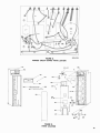
\SPEAKER
CABINET
I
CROSSOVER ASSEMBLY
SWITCH S1
el
-
INDUCTOR ASSEMBLY L2
FIGURE P.
Table 1.
Item
12
Qty.
Shure Part No.
-
CONNECTOR ASSEMBLY P I
RKC149 COMPONENTS
Crossover Assembly Components
Component
Use
1
1
90A2451
Crossover Assembly ( A l , S1)
Separates high and low frequencies,
and provides overvoltage protection
2
1
90A2112
Inductor Assembly (L2 with
terminal board)
With C2, provides high-frequency
driver protection
3
1
90A2070
Connector Assembly (PI with
leads
Connects input connectors and
speakers to A1
4
2
30A1002B
Carriage Bolt, Aluminum, 2"
Secures A1 and L2 to speaker cabinet
5
2
30H1035A
Screw, Round Head, Type A,
No. 10
6
2
30A775
Hex Nut, No. 10-24NC-2
Secures A1 and L2 to speaker cabinet
7
1
30A964A
Hex Locknut, No. 3432NEF-2B
Secures S1 to speaker cabinet
8
2
30A136
Lockwasher, % "
Secures A1 and L2 to speaker cabinet
9
1
30A960A
Lockwasher,
Secures S1 to speaker cabinet
10
2
31A1199
Spacer, Aluminum, 1"
Secures A1 to speaker cabinet
11
5
80A255
Cable Tie, Nylon
Secures leads of P I wiring harness
Y2"
,
Secures A1 to speaker cabinet
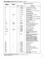
REPLACEMENT PARTS LIST (See Figures Q and R)
Reference
Designation
Replacement Kit Consists Of:
Replacement
Kit No.*
Q~Y.
Part No.
Description
-
90A2063
Crossover Network Assembly
A2
-
90A2068
High-Frequency Driver Assembly
(LS7-LS10, A3)
A3
-
-
90A2064
High-Frequency Driver Throat Assembly
(without drivers)
A4
-
-
90E1375
Jack Panel Assembly
(including connectors)
1
94A1182
High-Frequen~yDriver Diaphragm
and Coil Assembly
-
50A71
Capacitor, Metallized Mylar, Non-polarized,
4.7 ,F, 250 WVdc**
-
50871
Capacitor, Metallized Mylar, Non-polarized,
2.2 ,F, 250 WVdc**
-
86K630
Capacitor, Electrolytic, 50 F
,,
100 WVdc
A1
A5
C1
C2
C3
RKC132
A
-
D l-D4
RKC21
4
86A404
Silicon Rectifier, 100V, Y2A
J1-J6
RKC68
1
95B446
Connector, Phone Jack, 2-Conductor,
Open Circuit (Switchcraft 11)
90A2074
Socket Assembly, 9-Contact
J7
K1
L1, L2
LS1-LS6
A
RKC136
LS7-LS10
-
80A280
Relay, SPDT, 24 Vdc
-
95A640
Inductor, 1 mH, 0.6 Ohms
1
80A276
80A278
8-Inch Loudspeaker
(interchangeable parts)
-
80A275
High-Frequency Driver (see A5 for
replacement diaphragm and coil
assembly)
60A57
Speaker System Enclosure Assembly
(with Lower Rear Panel; without
Upper Rear Panel,
Horn, Grille Assembly, Crossover
Assembly, High-Frequency Driver
Assembly, Switch Panel Assembly,
Wheel Assemblies, Low-Frequency
Speakers, Jack Panel Assemblies,
Fiber Glass, Caution Plate, Frontand Rear Panel Trim, and Hardware)
90A2196
Radial Horn Assembly
MP I
-
-
MP2
-
-
48E35A
Front-Panel Rail
39A422
Nameplate
-
90A2062
Grille Assembly
-
-
11A141
Fiber Glass (Sound Absorber)
53A1335
Rotary Switch Panel (without Switch)
-
60A58
Upper Rear Panel
39A387
Caution Plate
-
53A1376A
Support Bracket, High-Frequency
Driver Assembly
MP3
MP4
MP5
MP6
-
MP7
MP8
MP9
MP10
-
*Parts listed as RKC Kits should be ordered by that number.
Any orders received for piece parts where RKC Kit number is shown will be shipped in RKC quantities.
"Selected for low dissipation factor.
REPLACEMENT PARTS LIST (Continued)
Reference
Designation
Replacement Kit Consists Of:
Replacement
Kit No.*
Qty.
-
-
MP15
-
-
MP16
-
MP17
Part No.
Description
95A638
Wheel
95A641
Cable Compartment Strap and Socket
Assembly
48A47A
Rail
36A336
Foam Screen
30C806C
Phillips Finishing Head ThreadCutting Screw, Black, #8, 1 in.
(Horn, Upper and Lower Rear Panels
to Enclosure)
-
30D832D
Phillips Flat Head Wood Screw, #6,
% in. (Front-Panel Rail to
Enclosure)
-
-
30H832D
Phillips Flat Head Wood Screw, #6,
1lh in. (Rear-Panel Rails to
Lower Rear Panel)
MP18
-
-
30A1007A
Capscrew, % in., Black, V'z13UN-3A Thread, 39'2 in. long
(Wheel Assembly)
MP19
-
-
30A1008A
Locknut, Y2-13UN-2B Thread,
in. (Wheel Assembly)
-
31A1224A
Wheel Bushing, Steel, 38.1 mm (1% in.)
OD (Wheel Assembly)
-
53A1334A
Washer, Steel, 34.9 mm (1YE in.) OD
(Wheel Assembly)
90A2155A
Front Bracket Assembly,
High-Frequency Driver Assembly
90A2070
Plug Assembly, 9-Pin
45HC758C
Power Resistor, 7.5 Ohms, 7W, 10%
45HC508C
Power Resistor, 5 Ohms, 7W, 10%
45HC408D
Power Resistor, 4 Ohms,
MPl1
MP12
MP13
MP14
MP20
A
MP21
-
MP22
-
P1
-
R1
-
R2
R3
R6
R7
-
A
-
S1
-
-
W1
RKC4
1
R8, R9
R10
-
45HC750D
3
h
low, 10%
Power Resistor, 75 Ohms, low, 10%
45CC470B
Resistor, Carbon Composition, 47
Ohms, Y2W, 10%
45EC400G
Power Resistor, 40 Ohms, 22W, 10%
45A40
Rheostat, 2k, 3W
55A106
Switch, Rotary, 6-Pole, 5-Position,
LOUDSPEAKER OPERATION
9081373
15.2m (50-foot) Cable Assembly
with Male Phone Plugs
'Parts listed as RKC Kits should be ordered by that number.
Any orders received for piece parts where RKC Kit number is shown will be shipped in RKC quantities.
FIGURE Q.
PRINTED CIRCUIT BOARD PARTS LOCATION
2063-6/595-5
ARCHITECTS' AND ENGINEERS' SPECIFICATIONS
The Speaker System shall be an extended range,
two-way speaker system designed for high sound-pressure-level reproduction of wide frequency range program material in sound reinforcement applications.
The Speaker System shall utilize six 8-inch cone-type
speakers with a total speaker cone area of 1097 cm2
(170 in2) and four high-frequency drivers. Pressure
sensitivity of the Speaker System shall be an EIA
rating of 54 dB at 9.2m (30 feet) from 1 milliwatt (equivalent to 102 dB at 1.2m--4 feet-with a I-watt input).
The sound power distribution shall be nominally
uniform over a 140" angle in the horizontal plane and
a 90" angle in the vertical plane. The Speaker System
enclosure shall be a bass reflex design to provide
extreme low-frequency enhancement, with low-frequency speakers column-mounted in a horn-loaded,
front-ported enclosure, and high-frequency drivers
coupled to a single radial horn.
The frequency
shall be uniform
Hz when driven
radiating into an
response of the Speaker System
and peak-free from 40 Hz to 15,000
by a constant-voltage amplifier and
acoustical half-space.
In conventional, full-range, single-amplifier operation, the continuous power rating of the Speaker
System shall be 200 watts maximum (57-volt source)
and the nominal impedance shall be 16 ohms. In
biamplified operation, the low-frequency section shall
accept up to 200 watts of program material and the
high-frequency section up to 100 watts.
The six low-frequency speakers shall be wired in
a series-parallel configuration and mounted in a
column configuration against the front baffle of the
Speaker System. The four high-frequency drivers
shall be wired in a series-parallel configuration at
the top and coupled to a throat adapter assembly
connected to a single radial horn. The high-frequency
drivers shall be wired through an integral passive
crossover network with a crossover frequency of
2600 Hz. A rear-panel LOUDSPEAKER OPERATION
Switch shall provide four selectable high-frequency
level positions of -4, - 2, 0 and + 2 dB for conventional full-range operation, and a BlAMP position for
biamplified operation. The inputs shall consist of a
pair of parallel-wired phone jacks for (1) conventional
full-range operation, (2) low-frequency biamplified operation, and (3) high-frequency biamplified operation.
The Speaker System enclosure shall be 15.9 mm
(% in.) wood construction covered with black, textured,
scuff-resistant vinyl, and have anodized, solid aluminum rear-panel rails. The enclosure shall have an
integral rear-panel handle and two heavy-duty hard
rubber wheels for mobility, and shall contain a cable
storage compartment at the top rear. The radial horn
shall be of high-density, structural urethane foam. A
plug-in 15.2111 (50-foot) speaker cable shall be supplied.
The Speaker System shall measure 1730 mm in height,
495 mm in width, and 517 mm in depth (68% in. X
19Y2 in. X 20% in.). The weight, including the supplied cable, shall be 64.5 kg (142 Ib).
The operating temperature range of the Speaker
System shall be -7°C to 43°C (20°F to 110°F). The
storage temperature range shall be -29°C to 71°C
(-20°F to 160°F). The Speaker System shall meet
all specifications when operated within the operating
temperature limits.
Any Speaker System not meeting all of the above
specifications, or having a sealed cabinet which prevents internal inspection and servicing, shall be
deemed unacceptable under this specification. The
Speaker System shall be a Shure Model SR108.