1
2 2 2 HARTREY AVE.. EVANSTON, IL. 6 0 2 0 4 U.S.A.
AREA CODE 3121866-2200
TWX: 9 1 0 . 2 3 1 - 0 0 4 8
.
CABLE: SHUREMICRO
TELEX: 7 2 - 4 3 8 1
I
DATA
SHEET
MODEL SR102 AND SR103
SPEAKER COLUMNS
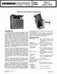
OPERATION AND SERVICE INSTRUCTIONS
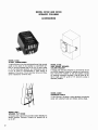
FIGURE A.
SR102 SPEAKER COLUMN
DESCRIPTION
The Shure Model SR102 and SR103 Speaker Columns are speaker systems designed for use with
Shure Model SR105 or similar high-power amplifiers
in sound reinforcement applications. When properly
installed and connected, the SR102 and SR103 Columns will provide outstanding performance. Their wide
frequency range, distortion-free reproduction and high
sound penetration power make them a valuable asset
to any sound reinforcement system. The Columns may
be used with either direct (4- lo 16-ohm) or constantvoltage 25- or 70-volt amplifier outputs.
Quality sound reproduction is achieved through the
use of two 10-inch and four b i n c h heavy-duty speakers, plus two high-frequency speakers which combine
the functions of dome radiators and acoustic horn
radiators. The tuned-rear-port enclosure design contributes to the highly directional pattern, which is
critical in achieving maximum audience penetration
and feedback reduction. The inductive-capacitive dividing networks maintain frequency-selective distribution of signals to the proper speakers.
The SR102 Column is a portable unit (see Figure
Copyright 1980, Shure Brothers Inc.
27A897 (TC)
FIGURE B.
SR103 SPEAKER COLUMN
A), and is primarily designed for temporary installation
either indoors or in a protected outdoor environment,
such as under an open pavilion. The Column may be
operated vertically on its own feet, or in a tilted position using an optional easel-type tubular stand (Shure
A3S-T). The SR102 Column is supplied with a 15m
(50-foot), 18-gauge, rubber-jacketed connecting cable
with locking phone plugs. The lower rear section of the
Column contains a cable storage compartment. The
SR102 Column is covered with a tough vinyl surface,
front and rear metal grilles are finished in durable
black enamel, and trim is anodized to minimize visible
wear. A retractile handle and balanced design contribute to ease of transporting.
The SR103 Column (see Figure B) is a weatherresistant unit, and is primarily designed for permanent
installation either indoors or in a protected outdoor
environment such as under the roof of an open pavilion. Electrical components, hardware and enclosure
surfaces have been designed to maximize resistance
to adverse weather, with drain holes provided to minimize moisture accumulation. Adhesives used in the
SR103 Column are moisture-resistant and trim and
fastening hardware have a high corrosion resistance.
Printed in U.S.A.
I
SPECIFICATIONS
SR102
SR103
---
Power Rating (Program Material)
100 watts max. (40-volt input, 16 ohms or
80-volt input, 64 ohms)
Power Load for Constant-Voltage
Operation
39 watts (25-volt input, 16 ohms)
78 watts (70.7-volt operation, 64 ohms)
Impedance
16 ohms nominal (25-volt strapping)
64 ohms nominal (70.7-volt strapping)
Frequency Response
100 Hz - 15 kHz (See Frequency Response,
Figure C)
5 kHz
Crossover Frequency
Sound Pressure Level (SPL)
EIA rating: 53 dB at 9.2m (30 ft) from 1 milliwatt;
equivalent to 101 dB at 1.2117(4 ft) with 1-watt input.
Phasing (Polarity)
Positive voltage on plus (+) terminal or phone jack
tip (SR102 only) produces positive sound pressure.
Horizontal Distribution
140" (See Polar Response, Figure D)
Vertical Distribution
65"
Environmental Resistance:
Operating Temperature
-6.7"
Storage Temperature
-29"
Humidity
Connectors
Mounting Hardware Supplied
to 43°C (20" to 110°F)
to 71°C (-20"
to 160°F)
Normal indoor/outdoor
Moisture-resistant
One 6-screw terminal
strip; two parallel-wired
phone jacks
One 6-screw terminal
strip
None
5/16-18 x 1Y2" screws
Overall Dimensions
(See Figures E and F)
1522 mm height (incl. feet)
x 354 mm width x 241 mm
depth (59-15/16 in. X 1315/16 in. X 9% in.)
1513 mm heightX352 mm
width x 240 mm depth
(59-9/16 in. X 13% in.
x 9-7/16 in.)
Weight
32.62 kg (72 Ib)
incl. cable
31.8 kg (70 Ib)
Construction
19 mm ( 3 ! in.) wood, black
vinyl covering, black
metal grilles, anodized
aluminum trim strips.
19 mm (Y4 in.) wood, black
vinyl covering, black
metal grilles, anodized
aluminum trim strips.
All surfaces (internal
and external) and all
components treated for
weather resistance.
SPECIFICATIONS (CONT'D)
SR102
SR103
Supplied Accessories
One 15m (50-foot)
heavy-duty cable with
locking phone plugs
-
Optional Accessories
A102A 70-Volt
Transformer
A3S-T Speaker Tilt
Stand*
A50XC 15m (50-foot)
Extension Cable
with male and female
phone plugs
A102A 70-Volt
Transformer
A103A Wall Mount
Speaker Column
Bracket
* Do not use Shure A3S-S Tilt Stand; this stand will not fit the SR102 Column.
/
-2 0
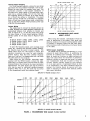
ANECHOIC RESPONSE
------ TYPICAL
BASS RESPONSE RISE
DUE TQ ROOM REVERBERATION
/
-3 0
LEGEND
60 8'0 1 0 0
200
400 6 0 0
IK
ZK
4K
6 K 8 K IOK
-
20K
2 5 0 Hz
FREQUENCY (Hz)
FIGURE C.
TYPICAL FREQUENCY RESPONSE
INSTALLATION
General
In planning a sound system using the SR102 or
SR103 Columns, care must be taken to observe the
horizontal (1400) and vertical (65O) sound distribution
of the Columns. Maximum coverage for source-oriented
installations is generally obtained with Columns on
each side of the sound source and as far forward
as possible, with each Column tilted slightly either
downward (for wall- or ceiling-mounted Columns) or
upward (for free-standing Columns). The angle of tilt
(assuming a single Column to either side of the sound
source) should be such that an imaginary line from
the center axis of the Column runs to the back row
of the audience area. The SR102 Column is designed
to accept the Shure A3S-T tilt stand, which provides
a maximum tilt angle of 30 degrees. For "clustered"
Column installations covering a wide area, each Column should be positioned so that its angle of coverage
coincides with that of the Column next to it as their
sound output enters the audience area.
When used for distributed-speaker systems, the
Columns are generally mounted at equidistant intervals
over the area to be covered. Wall- or ceiling-mounting
FIGURE D.
TYPICAL POLAR RESPONSE
is usually employed, although free-standing Columns
raised several feet or more from the floor are used
quite satisfactorily.
The problem of audience penetration may be likened
to illuminating a dark area with a floodlight: the object
is to provide maximum area coverage (audience) with
the available floodlights (columns). At the same time,
care must be taken to avoid illuminating reflective
surfaces. A blinding reflection (reverberation or
echoes) may be more of a problem than inadequate
coverage of the desired area.
Of the remaining common sound installation problems, acoustic feedback can usually be dealt with by
judicious Column/microphone placement, and/or the
use of feedback filters on the audio console. Background noise or acoustic absorption conditions generally require a greater volume level to maintain the
proper audio level. However, it must be remembered
that excessive volume may be intolerable to that part
of the audience nearest the Columns. In this case, or
in those cases where the architectural design leaves
audience areas that are not reached by the Columns,
the use of secondary or auxiliary speaker systems
should be considered. If these are used, the coincident
considerations of delay and phasing must also be
faced.
3
119 mm
(4-11/16 IN.)
I
L
FIGURE E.
4
SR102 COLUMN OVERALL DIMENSIONS
Direct Output Strapping
To connect the SR102 or SR103 Columns for use
with direct (4- to 16-ohm) amplifier outputs or standard constant-voltage, 25-volt lines, proceed as follows.
The SR102 Column rear panel contains a terminal
strip with six terminals (numbering, from left to right:
-, 4, 3, 2, 1, +) and two parallel-wired phone jacks
(see Figure G). The phone jacks are wired to correspond with the strapping of the terminal strip. Positive and negative inputs are located at either end
terminal as marked. Note that the SR103 Column rear
panel is identical except that it does not have phone
jacks.
Make sure the two straps connecting terminal 1 to
terminal 2 and terminal 3 to terminal 4 are in place.
This provides a total Column impedance of 16 ohms
(parallel internal wiring) with a power rating of 100
watts when operated from a 40-volt amplifier output.
When connected to a constant-voltage, 25-volt line
without a transformer, the Column will draw 39 watts.
The Column may also be connected in a "split"
configuration, either to provide redundancy-in case
of amplifier or speaker failure, the total Column output
will not be lost-or
to provide for separate inputs
from different sources, for instance, from both paging
and background music systems. This is accomplished
by removing the strapping between terminals 2 and 3,
and connecting one input to the plus (+) and 3 terminals, and the other input to the minus (-) and 2 terminals (see Figure G). The impedance for each half of the
Column with this configuration is 32 ohms, and the
power rating is 50 watts. When connected to a 25-volt
line (without a transformer), the power drawn by each
half of the Column is 20 watts.
~
a
b . 5 mm (3/8IN.)
FIGURE F.
SCREW
~
~5/16-18
~ X 1-1/2
.
FLAT WASHER (12 PLACES)
SR103 COLUMN OVERALL DIMENSIONS
The Columns are designed to accept program material resulting in power peaks up to 100 watts on a
continuous basis. However, sine-wave signals delivering 100 watts to a Column should be avoided in that
they present a much greater average power than does
program material. Consequently, when setting up or
adjusting a sound system with these Columns, avoid
the use of high-level, continuous-type test signals.
To insure safe operation of the Columns with program material inputs, do not connect them to an amplifier with an output capability greater than the following:
Voltage
1
Continuous Power To:
Connection
(Direct Output)
SPEAKER COLUMN MODEL 511102
P A P FOR 70 VOLT LINE 64 OHMS 78 WATTS
FIGURE G.
SR102 COLUMN REAR PANEL
I
70-Volt Output Strapping
For 70-volt (series) operation, remove the two straps
and insert one strap between terminals 2 and 3 only.
(Retain the extra strap for possible future use.) This
connection provides a total Column impedance of
64 ohms and a power rating of 100 watts when operated from a constant-voltage, 70.7-volt line. Note that
this strapping allows the Column to be used directly
on a 70-volt line without a transformer. The power
drawn from the 70-volt line is 78 watts. For operation
from a 70-volt line at lower power levels, a transformer
such as the Shure Model A102A provides power taps
of 50, 25, 12.5 and 6 watts.
Column Wiring
The cables used to connect the Columns should be
at least 18-gauge and rubber-jacketed. Determine the
approximate distance from amplifier to Column and
refer to Figures H or J to find the proper wire gauge
for direct output or 70-volt output operation. Recommended cables for the sizes listed in Figures H and
J are:
#84607
l8
Gauge:
16 Gauge: Belden #8470, #8471,
14 Gauge: Belden #8473
12 Gauge: Belden #8477
#84619
#97401
#8452
#8472
To avoid the frequency losses, poor coverage, dead
zones, etc., resulting from improper speaker phasing,
the Columns must be wired in proper polarity. The
cables listed above are color-coded to ensure that
identical connections are used for each amplifierColumn hookup. Note that even common 18-gauge
lamp cord ("zip cord") is phased-coded with ribs along
the outer jacket of one conductor.
When using the 15m (50-foot), heavy-duty cable
supplied with the SR102 Column, connect the rightangle plug to a Column phone jack and twist the cable
downward behind the locking bar to prevent accidental
disconnection. The other phone jack and the terminal
strip may be used for additional, parallel-connected
Columns. When not in use, the cable may be stored
in the compartment below the connector panel.
DISTANCE
AMPLIFIER-TO-SPEAKER
DISTANCE (METERS1
-
8
#
Y
D
L!
2
S
rn
I
s
V)
FIGURE H.
RECOMMENDED WIRE GAUGE:
DIRECT OUTPUT
When wiring the Columns, consideration should be
given to positioning of the cables. While most local
electrical codes do not require locating speaker cables
in conduits or raceways, make sure that cable placement minimizes traffic interference and physical abuse
to the cable.
SR102 Column Installation
The SR102 may be operated free-standing, or on an
optional tilt stand (Shure ASS-T). In positioning the
Columns for optimum sound coverage, care must be
taken to locate the Columns on stable surfaces and
away from areas where the movement of performers,
audience, curtains or stage sets may cause it to topple
over. Consideration must also be given to heavy air
currents, whether naturally caused by wind outd'oors
or in an open pavilion, or generated indoors by fans
or air conditioners. If the above conditions cannot be
avoided, the Columns should be secured with rope,
cable or strapping to maintain their physical position
and prevent accidents.
AMPLI FIER-TO-SPEAKER DISTANCE (FEET
AMPLIFIER-TO-SPEAKER DISTANCE (METERS)
FIGURE J.
(PEETI
AMPLIFER-TO-SPEAKER
RECOMMENDED WIRE GAUGE: 70-VOLT OUTPUT
If the Column is to be used at a low power on a
constant-voltage, 70-volt system, a Shure A1 02A 70-Volt
Transformer must be connected between the amplifier
and Columns.
WARNING
If the A102A Transformer is to be mounted
to the Column, it should be positioned at
the lower rear, just above the jack panel,
in order to improve Column stability.
Note that the Transformer should also be electrically
located as close to the Column as possible; therefore
the optimum mounting location just above the jack
panel should be used. Mounting of the transformer
adds approximately 82 mm (31/4 in.) to the total depth
of the Column.
SR103 Column Installation
The SR103 Column may be operated free-standing,
or suspended by means of: (1) chains or armored
cable attached to the four mounting screws, one at
each upper and lower side corner (see Figure B), or
(2) a Shure Model A103A Wall Mount Speaker Column
Bracket. In operating the SR103 Column in a freestanding mode, the same considerations should be
given regarding placement and security as were stated
for the SR102 Column: platform stability, minimal traffic
and air current avoidance. Use physical restraints if
necessary.
To suspend the Column, first loosen the 5/16-18
mounting screws at each side corner. (Note that these
four screws may be replaced by four 5/16-18 x 11/zV
eyebolts-not supplied-if desired.) To avoid the possibility of loosening of the mounting bolts or eyebolts
due to vibration, it is recommended that a commercial
sealant such as LOCTITE Grade C or pipe joint compound be applied to the screw threads before tightening them. Be sure that the chain or cable used is of
sufficient strength to restrain the Column; at least
135 kg (300 Ib) test strength is recommended.
WARNING
It is extremely important that both the method of securing the chain or cable and the
mounting surface are adequate to support
the weight of the Column. Inadequate support in Column and wall/ceiling mounting
hardware, mounting chain or cable, or wall
or ceiling mounting surface may result in a
hazardous operating condition. When mounting the Column in a plaster, or plasterboard, or other thinwall-type ceiling or wall,
be sure to fasten hardware to firmly supported studs or beams. A backplate securing the hardware on the opposite side of
the wall should be used if wall construction
permits.
Carefully attach the ceiling chains or cables to the
upper mounting screws at the desired height. Attach
the remaining wall or ceiling chains or cables to the
lower mounting screws, and draw them up to the wall
or ceiling to form the desired angle of the Column
toward the audience. Secure all chains or cables
firmly, and tighten the speaker mounting screws. (For
instructions on mounting the SR103 Column using
the wall bracket which permits 19O of horizontal pivoting, 18O of tilt-up and 12O of tilt-down, refer to the data
sheet supplied with the bracket assembly.)
Checking Sound Coverage
When the Columns, amplifier and other equipment
have been installed and connected, apply a fairly constant level signal to the system (preferably program
material) and walk around the audience area. Listen
for a smooth, even output from the Columns, with
minimal differences in volume and tone, and no disaudio purtortion or "dead spots." A dead spot-for
poses, an audience area where no sound is heard, or
where the sound level is appreciably lower than the
rest of the audience area - may mean that the
Columns are not covering that area, or that the Column
speaker wires are connected out-of-phase. Proper
phasing may be readily determined by checking the
connections to the terminal strips on each Column to
make sure they are the same, but inadequate coverage
generally requires repositioning the Columns. The dead
area should be carefully examined to determine that
the problem can be corrected without resorting to auxiliary speakers.
SERVICE INSTRUCTIONS
Speaker Servicing
1. Disconnect speaker cables from phone jacks and/
or terminal strip.
2. Using an ohmmeter, measure the resistance between the plus (+) and minus (-) terminal screws.
The dc resistance should be 11 to 15 ohms (16
ohms nominal impedance) when strapped for 25volt operation, and 44 to 60 ohms (64 ohms nominal impedance) when strapped for 70-volt operation.
3. The SR102 and SR103 Columns are symmetrical
and contain two identical "sets" of four speakers
(see Figure K). If a speaker is suspected of being
faulty, the fault may be localized to one of the
two sets of speakers as follows. With all strapping
removed, measure the resistance between the plus
(+) and 3 terminals. A normal condition in the top
set of speakers is indicated by a nominal reading
of 26 ohms. Measure the resistance between the
negative ( - ) and 2 terminals. A normal indication
in the bottom set of speakers is indicated by a
nominal reading of 26 ohms.
4. To gain access to the individual speakers, remove
the six Phillips head screws securing each trim
strip to the front of the Column. The front-panel
grille and foam pad assembly can now be removed,
exposing the speaker configuration.
(NOTE: When removing the assembly, be careful
not to separate the grille from the foam pad.) Remove the vertical wood retainer strip spanning the
8-inch speakers.
5. When the faulty condition has been localized, remove the top or bottom &inch speaker, depending
on which set of four speakers is suspect. Removal
of these speakers will provide access to the wiring
associated with the other speakers of that set.
(NOTE: If a power screwdriver is used to remove the
retainer strip screws, excessive force may loosen
the teenuts and cause them to drop into the enclosure.) Remove the &inch speaker by removing
the four locknuts and flat washers (using an 11/32"
nutdriver), and gently lifting the speaker out and
resting it on the baffle board.
6. Using an ohmmeter, measure the resistance of
each speaker voice coil in the set. A clicking sound
will be made by a "good" speaker when an ohmmeter is connected or disconnected. Note that the
high-frequency speakers (LS2, LS7) cannot be
properly measured without unsoldering the associated inductor (L1, L2; see Figure K) though
the "click" produced by the ohmmeter can be
heard without unsoldering the inductor. Each 10inch speaker should measure between 10 and 14
ohms. Each 8-inch speaker should measure between 6 and 8 ohms. Each high-frequency speaker
should measure between 13 and 15 ohms. Readings
outside these limits indicate possible failures. Replace any speakers found defective.
7. If the above tests do not locate the defective unit,
apply a small ac voltage from a sweep oscillator
and amplifier to each speaker individually (approximately 4V, 50 to 10 kHz for 8- and 10-inch speakers;
approximately 2V, 3 kHz to 15 kHz for high-frequency speakers).
COLOR-CODED
TS I
7,
TERMINAL
TOP
SET
WARNING
Sound pressure levels generated by this
test may be damaging to your hearing. Aim
speakers away from listeners and toward
sound-absorbent material (curtains, blanket,
etc.). Carefully adjust test signal amplitude
to avoid unnecessarily high sound pressure
levels for prolonged periods.
As the test signal frequency is varied, any erratic
buzzes or rattles indicate possible failure.
8. Reconnect the high-frequency speaker inductors
and replace and tighten the &inch speakers. Replace .the vertical retainer strip, grille and pad assembly, and color and trim strips. Tighten all hardware to avoid rattles.
High-Frequency Speaker Diaphragm and
Coil Assembly Replacement
The high-frequency speakers (LS2, LS7) may be
supplied in either of two configurations. Type I employs three screws and three 8-32 x 11/32" nuts to
hold the horn to the magnetic structure. Type II employs three screws and three threaded holes in the
circular mounting flange of the horn to hold the horn
to the magnetic structure.
Replace the diaphragm and coil assembly in the
high-frequency speaker as follows:
1. Remove the high-frequency speaker i r o m the
enclosure by first removing the 10" speaker
next to it.
FIGURE K.
CIRCUIT DIAGRAM
2. Remove the three 8-32 x 11/32" locknuts and
washers securing the speaker to the baffle. Do
not allow the speaker to drop into the enclosure
when removed.
3. Unsolder the leads connected to the speaker
terminals and remove the speaker from the
enclosure.
4. Prepare a clean work area, free of drafts and
metallic dust and chips. Cover the work area
with clean kraft paper or newspaper.
5. Place the speaker on the work surface.
a. Type I: Remove the three 8-32 x 11/32" nuts
and screws securing the horn to the magnetic structure; remove the horn (see ~ i g u r e
L).
b. Type II: Remove the three screws securing
the horn to the magnetic structure; remove
the horn (see Figure L).
6. Remove the diaphragm and coil assembly by
lifting upward. This is a snug fit, and a gentle
prying force may be required.
7. Clean the voice coil gap in the magnetic structure as follows. Insert a strip of masking tape
into the voice coil gap with the adhesive side
outward. Draw the tape around the gap several
times to provide good wiping action. Repeat the
process with a new piece of tape with the
adhesive side facing inward.
HORN
DIAPHRAGM
8 COlL ASSEMBLY
CLEARANCE HOLES (3), TYPE I ONLY OR
THREADED HOLES (3),TYPE I
I ONLY
0
y
I
NUTS (3), TYPE
I ONLY
I
I
LOCATOR
PINS
(3)
CLEARANCE HOLES (3)
MOUNTING
SCREWS (3)
FIGURE L.
DIAPHRAGM AND COlL ASSEMBLY REPLACEMENT
The assembly is a delicate part. Do not
touch the voice coil and bobbin, or allow
it to come in contact with the work surface, tools, etc. If the assembly is placed
on the work surface, rest it on the diaphragm with the voice coil upward.
8. Assemble the new diaphragm and coil assembly
to the magnetic structure with the coil facing
the magnetic structure. Locate the three small
holes in the diaphragm and coil assembly over
the locator pins in the magnetic structure. The
three large holes in the diaphragm and coil assembly will line up with the screw holes in the
magnetic structure.
9. Assemble the horn to the magnetic structure.
Magnetic attraction between horn and
magnetic structure will cause the horn
to "jump" to the magnetic surface; use
extreme care to avoid crushing the
diaphragm.
a. Type I: Position the large holes in the horn
over the three mounting holes in the magnetic structure, making sure that one straight
edge of the horn flange is aligned with the
straight edge (between solder terminals) of
the diaphragm and coil assembly.
b. Type II: Position the threaded holes in the
horn over the screw clearance holes in the
magnetic structure, making sure that one
straight edge of the horn flange is aligned
with the straight edge (between solder terminals) of the diaphragm and coil assembly.
10. a. Type I: Replace the three screws and 8-32
x 11/32" nuts and tighten them securely but
do not overtighten.
b. Type II: Replace the three screws and tighten them securely but do not overtighten.
11. Reassemble the high-frequency speaker into
the speaker enclosure and reassemble the
Column.
Nameplate
Should it become necessary to replace or re-fasten
the front-panel nameplate, be sure to use a heavy-duty,
weather-resistant adhesive. Goodyear PLIOBOND or
equivalent cement is recommended.
GUARANTEE
This Shure product is guaranteed in normal use to
be free from electrical and mechanical defects for a
period of one year from date of purchase. Please
retain proof of purchase date. This guarantee includes
all parts and labor. This guarantee is in lieu of any
and all other guarantees or warranties, express or
implied, and there shall be no recovery for any consequential or incidental damages.
SHIPPING INSTRUCTIONS
Carefully repack the unit and return it prepaid to:
Shure Brothers Incorporated
Attention: Service Department
1501 West Shure Drive
Arlington Heights, Illinois 60004
If outside the United States, return the unit to your
dealer or Authorized Shure Service Center for repair.
The unit will be returned to you prepaid.
REPLACEMENT PARTS LIST (see Figure M)
Reference
Designation
Replacement Kit Consists Of:
Replacement
Kit No.*
Qty.
Part No.
Description
A l , A2
-
Crossover Network Assembly
(Capacitor, Inductor, Terminal Board)
A3
-
Rear Panel Assembly with connectors
(SR102 only)
Rear Panel Assembly with connectors
(SR103 only)
A3
A4
C I , C2
1
-
Capacitor, Mylar, 1 pF, l o % ,
250 WVdc
Inductor, 0.5 mH
L1, L2
LSI, LS8
1
LS2, LS7
-
LS3-LS6
High-Frequency Loudspeaker
Diaphragm and Coil Assembly
1
10-inch Loudspeaker
High-Frequency Loudspeaker (see A4
for replacement diaphragm and coil
assembly)
8-inch Loudspeaker
MPI
-
M P2
1
MP3
-
Rear-Panel Grille and Pad Assembly
M P4
-
Column Enclosure Assembly (including
Handle, Feet, Rear-Panel Grille and Pad
Assemblies, Fiber Glass, Cable Compartment Strip Assembly; without
Speakers, Crossover Networks, Retainer
Strip, Front-Panel Grille and Pad
Assembly, Rails, Nameplate)
(SR102 only)
M P4
-
Column Enclosure Assembly
(including Rear-Panel Grille and Pad
Assemblies, Fiber Glass, Side-Panel
Mounting Hardware; without Speakers,
Crossover Networks, Retainer Strip,
Front-Panel Grille and Pad Assembly,
Rails, Nameplate)
(SR103 only)
M P5
-
Vertical Retainer Strip
MP6
-
Front-Panel Grille and Pad Assembly
MP7
-
Left Front-Panel Rail
MP8
-
Right Front-Panel Rail
M P9
MPIO
Side Rail (SR102 only)
Retractile Handle Assembly (SR102 only)
Gold Left Rail Insert
Nameplate
Foot (SR102 only)
MP11
4
MP12
-
Fiber Glass (Sound Absorber)
MP13
-
Cable Compartment Strap and
Socket Assembly (SR102 only)
MP14
I -
Phillips Flat Head Wood Screw, #6,
1Ye'' (Front Rails)
Parts listed as RKC Kits should be ordered by that kit number.
Any orders received for piece parts where RKC Kit number is shown will be shipped in RKC quantities
REPLACEMENT PARTS LIST (see Figure M)
Reference
Designation
(CONT'D)
Replacement Kit Consists Of:
Replacement
Kit No.*
Qty.
Description
Part No.
MP15
-
-
30B882A
Phillips Flat Head Wood Screw, #6,
3h" (Side Rails) (SR102 only)
MP16
-
-
30H903C
Phillips Round Head Machine Screw,
#lo-32, Y4" (Feet and Tilt Stand)
(SR102 only)
MP17
-
-
30A1002B
Carriage Bolt, Aluminum, 2"
(Crossover Network)
RKC4
1
9081373
50-Foot Cable Assembly with Male
Phone Plugs (SR102 only)
W1
* Parts listed as RKC Kits should be ordered by that kit number.
Any orders received for piece parts where RKC Kit number is shown will be shipped in RKC quantities.
MP15\
MPI
NOTE: SR102
DESCRIBED IN
COLUMN SHOWN; SR103 PARTS
REPLACEMENT PARTS LIST.
FIGURE M.
SPEAKER COLUMN PARTS LOCATION
ARCHITECTS' AND ENGINEERS'
SPECIFICATIONS
SR102 Speaker Column
The Speaker Column shall be a portable speaker
column designed for sound reinforcement applications.
The Column shall utilize two 10-inch and four 8-inch
cone-type speakers with a total speaker cone area of
1419 cm? (220 in2), and two high-frequency horn-type
speakers. Pressure sensitivity of the Column shall be
an EIA rating of 53 dB at 9.2m (30 feet) from 1 milliwatt (equivalent to 101 dB at 1.2111-4
feet-with
a
I-watt input).
The sound power distribution shall be nominally
uniform over a 1400 angle in the horizontal plane and
a 65O angle in the vertical plane. The Column enclosure shall be acoustically rear-ported to provide a
feedback-minimizing, horizontal polarization pattern.
The usable frequency response of the Column shall
be uniform and peak-free from 100 Hz to 15,000 Hz
when driven by a constant-voltage amplifier.
The continuous power rating of the Column shall
be 100 watts maximum and the nominal impedance
shall be 16 ohms when driven from a 40-volt source.
When driven from a constant-voltage 70.7-volt line,
the continuous power rating shall be 100 watts maximum and the nominal impedance shall be 64 ohms.
All eight speakers shall be mounted against the
front baffle of the Column. The top four speakers (one
10-inch, two &inch and one high-frequency) shall be
wired with a 5 kHz crossover network in a seriesparallel configuration and connected to a six-terminal
barrier terminal strip and two phone jacks. The bottom
four speakers shall be wired in a similar manner. By
appropriate strapping on the terminal strip, the two
speaker networks shall be connected in parallel for a
25-volt line with a nominal impedance of 16 ohms,
or in series for a 70-volt line with a nominal impedance
of 64 ohms.
The speaker enclosure shall be 19 mm (3h in.) wood
construction covered with black, scuff-resistant vinyl
and have edge-protecting, anodized, solid aluminum
front and side rails. The enclosure shall have a retractile handle for portability and a cable storage compartment at the bottom. A plug-in 50-foot speaker cable
shall be supplied. The Column shall measure 1522 mm
in height (including feet), 354 mm in width, and 241 mm
in depth (59-15116 in.xl3-15/16 in. X9Vz in.) The
weight, including the supplied cable, shall be 32.62 kg
(72 Ib).
The operating temperature range of the Column
shall be -6.7"C to 43°C (20°F to 110°F). The storage
temperature range shall be -29°C to 71°C (-20°F to
160°F). The Column shall meet all specifications when
operated within the operating temperature limits.
Any Speaker Column not meeting all of the above
specifications, or having a sealed cabinet which pre-
vents internal inspection and servicing, shall be
deemed unacceptable under this specification. The
Speaker Column shall be a Shure Model SR102.
SR103 Speaker Column
The Speaker Column shall be a speaker column
designed for indoor or outdoor use in sound reinforcement applications. The Column shall utilize two 10-inch
and four 8-inch cone-type speakers with a total speaker cone area of 1419 cm"220
in2), and two high-frequency horn-type speakers. Pressure sensitivity of the
Column shall be an EIA rating of 53 dB at 9.2m (30
feet) from 1 milliwatt (equivalent to 101 dB at 1.2m4 feet-with a 1-watt input).
The sound power distribution shall be nominally
uniform over a 140" angle in the horizontal plane and
a 65" angle in the vertical plane. The Column enclosure shall be acoustically rear-ported to provide a
feedback-minimizing, horizontal polarization pattern.
The usable frequency response of the Column
shall be uniform and peak-free from 100 Hz to 15,000
Hz when driven by a constant-voltage amplifier.
The continuous power rating of the Column shall
be 100 watts maximum and the nominal impedance
shall be 16 ohms when driven from a 40-volt source.
When driven from a constant-voltage 70.7-volt line,
the continuous power rating shall be 100 watts maximum and the nominal impedance shall be 64 ohms.
All eight speakers shall be mounted against the
front baffle of the Column. The top four speakers (one
10-inch, two 8-inch and one high-frequency) shall be
wired with a 5 kHz crossover network in a seriesparallel configuration and connected to a six-terminal
barrier terminal strip. The bottom four speakers shall
be wired in a similar manner. By appropriate strapping
of the terminal strip, the two speaker networks shall
be connected in parallel for a 25-volt line with a
nominal impedance of 16 ohms, or in series for a
70-volt line with a nominal impedance of 64 ohms.
The speaker enclosure shall be 19 mm (3h in.) wood
construction covered with black, scuff-resistant vinyl
and have anodized, solid aluminum front rails. All surfaces (internal and external) and all components shall
be treated for weather resistance. The Column shall
measure 1513 mm in height, 352 mm in width, and
240 mm in depth (59-9116 in. X 13% in. X 9-7/16 in.).
The weight shall be 31.8 kg (70 Ib).
The operating temperature range of the Column
shall be -6.7"C to 43°C (20°F to 110°F). The storage
temperature range shall be -29°C to 71°C (-20°F to
160°F). The Column shall meet all specifications when
operating within the operating temperature limits.
Any Speaker Column not meeting all of the above
specifications, or having a sealed cabinet which prevents internal inspection and servicing, shall be
deemed unacceptable under this specification. The
Speaker Column shall be a Shure Model SR103.
MODEL SR102 AND SR103
SPEAKER COLUMNS
ACCESSORIES
MODEL A102A
70-VOLT TRANSFORMER
A high-efficiency, low-loss autotransformer that mounts
easily on the back of any speaker or convenient surface to provide wattage taps of 50, 25, 12 and 6 watts
in 70-volt distributed systems, and impedance taps of
8 and 16 ohms to accommodate a wide variety of
speakers. Five-screw 70-volt terminal strip and threescrew impedance terminal strip.
MODEL A103A
WALL MOUNT SPEAKER
COLUMN BRACKET
A strong wall bracket designed to permanently mount
the SR103 Speaker Column on almost any vertical surface. Allows the installer to aim the speaker column
for optimum audience coverage. Tilts as much as 19"
left or right, and 18" uptilt or 12" down-tilt. Locks in
selected position.
MODEL A50XC
EXTENSION CABLE
A 15m (50-foot), 18-gauge, rubber-jacketed connecting
cable with attached male and female phone plugs.
MODEL ASS-T
SPEAKER TILT STAND
A tubular steel stand that provides added stability for
SR102 Speaker Columns. Permits an upward tilt of
up to 30".