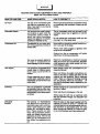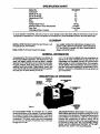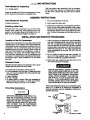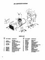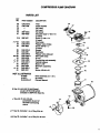
1
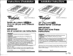
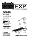
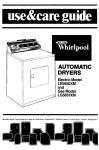
SE_AR8
OWNERS
MANUAL
MODEL NO.
919,150270
CRAFTSMAN
COMPACT AIR COMPRESSOR
Listed
7"21Y
Record In the spaces provided.
Air
Compressor
(1) The model number which can be
found On the Io1_1 on the back of tha
unit.
(2) The date €ode number which can be
found on t_e foil lahet on me bottom
of the unlL
IMPORTANT
Read the Safety Guideline=;
and All Instructions
Carefully Before Operstlng
ASSEMBLY
OPERATION
MAINTENANCE
REPAIR PARTS
Sears,
S1_30-0_2-C
!t/88
Roebuck
Retain mue numbers for future
refelr_,
and Co., Chicago,
IL 60684
U.S.A.
TABLE OF CONTENTS
WARRANTY
SAFETY
.......................................................
GUIDELINES
WARNING
GENERAL
AND CHART ..............................
3
CHART .................................................
SPECIFICATION
.GLOSSARY
3
4
CHART ..........................................
s
........................................................
INFORMATION
DESCRIPTION
UNPACKING
,5
........................................
OF OPERATION
INSTRUCTIONS
5
..................................
5
.....................................
6
ASSEMBLY
INSTRUCTIONS
......................................
Tools Needed for AssemDly.........................................
Installing RubberFeet .............................................
6
6
6
INSTALLATION
AND START-UP PROCEDURES
L_ation of Air Compressor.........................................
.................
Extension Cords ..................................................
GroundingInstructions.............................................
OPERATING
PROCEDURES
6
6
6
6
.....................................
7
MAINTENANCE
...................................................
Air Int_<eFilter- Replacement......................................
7
7
Motor ............................................................
WiringDiagram...........................................
STORAGE
.........................................................
GUIDE TO ACCESSORIES
TROUBLESHOOTING
PUMP
8
8
8
GUIDE .....................................
9
DIAGRAM
...............................
Parts List .......................................................
HOW TO ORDER
"........
.................................
AIR COMPRESSOR
DIAGRAM ...................................
ust ........................................................
COMPRESSOR
7
REPAIR
PARTS ...............................
lo
_o
11
11
12
FULL ONE YEAR WARRANTY
ON AIR COMPRESSORS
If this air compressor fails due to a def_-t in material or workmanship within one year from the
date of purchase, return it to the nearest Sears Service Canter/Department throughout the United
States and Sears will repair it, free of charge.
If this air compressor is used for commercial or rental purposes, the warranty will apply for ninety
days from the date of purchase,
This warranty gives you specifm legal rights and you may have other rights which vary from state
to state.
Sears, Roebuck and Co., Sears Tower, Dept. 698/731 CR.W, Chicago, IL 60884
SAFETY GUIDELINES
This manual cont_ns information that is important for you tO know and understand.
This information relates to YOUR SAFETY and PREVENTING
EQUIPMENT
PROBLEMS.
To help yOu recognize this information, we use the following symbols. Please read the manual and
pay attention to tho_e sections.
URGENT SAFETY INFORMATION - A
HAZARD THAT W/LL CAUSE SERIOUS
INJURY OR LOSS OF LIFE.
information
for preventing
damage 1o
equipment.
L
NOTE
WARNING
I
..........
IIIIIIIIIIII
IMPORTANT SAFETY INFORMATION A HAZARD
THAT MIGHT
CAUSE
SERIOUS iNJURY OR LOSS OF LIFE.
Information that you should pay special
attention to.
3
HAZARDSCAN
N,
,
OCCUR IF EQUIPMENT IS NOT USED PROPERLY.
READ THE FOLLOWING CHART
,,,,,,,
,,,,,,,i
WHAT TO LOOK FOR
,,,,,,,,,
,1111
HOW TO PREVENT
IT
Hot Parts
The top of the compressor gets
hot when the compresSOr is running. If you touch it, you may be
seriously burned.
Nevertouchthetopoftheaircompressor
during
or immediately after operation. Always use the
handle,
Flammabie _/a_
It is normal for the motor's etectrical contacts to spark when the
compressor starts or stops. A
spark can ignite flammable
vapors from gasoline or SOlvents,
causing an explosion or fire.
The air compressor must only be used in well
ventilated areas, free of gasoline or SOlvent
vapors.
om
Do not operate the compressor white you are
carrying it, or in the spray amiL
;....................................................
Compressed air can propel dust,
Never point any nozzle or sprayer toward a per-
eased Ai
dirt or loose particles it comes in
contact with.
Son or any part of the body.
Always wear safety goggles or glasses when
using the air compre6sor.
Always turn the air compressor
attaching or removing accessodas.
Toxic Vapors ....
Too much air pressure applied to
air tools or accessories
can
cause damage or risk of bursting.
Check the manufacturer's maximum pressure
rating for air tools and accessodes. Regulator
outlet pressure must never e_ceed the maximum pressure rating.
It is normal for compressed air to
contain toxic or irritating vapors.
Such vapors are harmful if
inhaled.
Never dim°tly inhale the compressed air produceq by this unit.
Certain materials you are spraying (like palm, weed Idller, sand or
insecticide) can be harmful if you
inhale them.
,,
Electricity
Unsuitable
Solvents
off before
Read and follow the safety instructions provtded on the label or safety data sheet for the
material you are spraying. Use a respirator
mask if there is a chance of inhaling anything
you are spraying. Read all instructions.., be
sum that the respirator mask is suitable for yOur
application.
,,,,,
Your air compresSOr is powered
by electricity. Like any other electrically powered device, if It is not
used property itcan cause electrical shock.
Aiways unplug the air _pressor
tenance or repair.
Never use the air compressor in the rain.
Always plug the cord into an electrical outlet
with the specified voltage and adequate fuse
protection.
.........
Read the label
and Methylene
Chloride can
chemically react with aluminum
used in paint spray guns, paint
pumps, etc., and cause an explosion. These solvents can also
react with galvanized components and cause corrosion and
weakening of parts, This wilt not
affect your air compressor, but it
may affect the equipment you
use.
priorto main- "
ii
, i
,,,i,
or data sheet supplied with the
material you intend to spray. If it contains the
solvents listed do not use accessories that contain aluminum or galvanized parts. You must
either change the material you intend to spray,
or use only stainless steel spray equipment.
SPECIFICATION CHART
Model No.
919.1S0270
Horsepower
SCFM @ 40 psig
SCFM @ 9O psig
Disptecement CFM
Bore
Stroke
Voltage-Single Phase
Minimum Branch Circuit Requtrem_mt
"Fuse Type
Amperage at Max. Pressure
_/,
2.7
2.0
4.0
2%"
,9"
110-120
15 AMPS
Time Delay
10.6
"A circuit breaker is preferred. Use only a fuse or circuit breaker that is the same rating as the branch cimult the air
compressor is operated on. If the air compressor is connected to a circuit pmtented by fuses, use time delay fuses.
GLOSSARY
SCFM or CFM: Standard Cubic Feet per Minute; a unit
of measurement of air delivery.
PSIG Or PSI: Pounds per Square inch gauge.
U.L Listed: Underwriter laboratories; samples of cornpmssor outfits, takan from production, were submitted to
U.L and found to comply with their requirements for
design and performance.
GENERAL INFORMATION
Congratutetions! You have pumhased a one cylinder, _Y=
HP compact oilisss compressor. The absence of a tank
gives you added mobility as well as ease In storage,
while the _/,=HP motor allows you to utilize many air tools,
including Inflators, blow guns, spray guns. air brushes,
caulking guns and etchers. OJIless design means you
never have to add oil and its oi!tses feature also guarantees that you will spray entirely oil-free air.
A %" x 15' all"hose is supplied with your compreSsor, aS
well as an air chuck, Accossodes for use with your new
compressor are available through the current Sears
sales catalog, or at full line Sears stores. Your compressor witl operate many accessodes. Check the pressure
and flow rating recommended by the accessory manufacturer- be sure it is compatible with the air delivery of
your cOmpressor.
DESCRIPTION OF OPERATION
AIR
F/gum I
Air Compressor Pump: To compress air, the piston
moves up and down in the cylinder. On the downstroke,
air isdrawn in through the air intake muffler° The exhaust
valve remains closed. On the upstroke of the piston, air is
compressed. The intake valves close and compressed
air is forced out through the exhaust valve and then
through the air hose.
Adjustable Pressure Valve Knob: The pressure valve
knob controls the amount of pressure going from the air
compressor to the accessory, Pressure can be set at any
point between 10 and 100 RS,I. (100 P.S.I. is the highest
pressure this compressor will deliver,) Always set the
pressure valve knob at or below the required pressure for
the accessory being used, THE ADJUSTABLE PRESSURE VALVE KNOB MUST BE SET AT "START"
BEFORE YOU START THE COMPRESSOR,
5
INSTRUCTIONS
Tools Needed for Unpacking
A +/2"socket wrench.
Grasp the handle _und lift the air compressor out of the
carton. Remove the styrofoam and plastic brace.
Note the plastic brace attached to the air compres_
sot"by a hex screw, Using a _h" socket wrench, remove
the hex screw. Dlacard both the screw and the plastic
brace.
ASSEMBLY INSTRUCTIONS
Tools Needed for Assembly
Turn your compressor on its side.
.
2, insert eyelet into rubber fool
A phillips screwdriver.
Installing rubber feet.
Enclosed with this compressor you will find three
screws, three rubber feet, three eyelets and two flat
washers. You will attach these to the bottom of the unit.
Refer to the air compressor diagram on page 10,
3, Center hole in rubber foot over fiat washer and hole in
bottom of unit. Insert screw and tighten. Note: Longer
screws and flat washers are to be used under front
two feet on/y. Shorter screw is to be used on back foot
only. Continue this process until all three feet are on
unit,
INSTALLATION AND STAR'FUP PROCEDURES
Location of the Air Compressor
Operate the air compressor in a dry, dean, cool and well
ventilated area, The air intake muffler must be kept clear
of obstructions which could reduce air delivery of the air
compressor, The air compressor pump and case are
designed to allow for proper cooling. Clean or blow off
dust or dirt that collects on air compressor. A clean air
compressor runs cooler and provides longer service.
The ventilation openings on your air compressor are
necessary to maintain proper operating temperature.
Do not place rags or other containers on or near these
openings.
Extension Cords
.
The air compressor is designed for 120 volt operation
only and is equipped with a cord having a grounding
wire with an appmgriate grounding plug. The plug
must be used with an outtet that has been instalted
and grounded in accordance with all local codes and
ordinances (see figure 2). The outlet must have the
same configuration as the plug. DO NOT USE AN
ADAPTER.
2. Do not modify the plug that has been provided. If it
does not fit the available outlet, the correct outlet
should be installed by a qualified electrician.
3. Before each use, inspect the plug and cord. Do not
use if them are signs of damage.
USe extra air hose instead of an extension cord TOavoid
voltage drop end power loss to the motor.
If you mum use an extension cord be sure it is:
• a 3-wire extension cord that has a 3-blade grounding
plug, and a 3-slot receptacle that will accept the plug
on the compressor,
• in good condition.
• 50 feet or shorter.
• 12 gauge (AWG) or larger. (Wire size increases as
gauge number decreases.) 10 AWG and 8 AWG,
may also be used, Do not use 14 or 16 AWG.
itthese grounding insttuotions are not completely understood, or if in doubt as to wh_her the compressor is
properly grounded, have the installation _
by a
qualified electrician.
Grounding Instructions
=,,.
....,
l
&RNING
RISK OF ELECTRICAL SHOCK, IF REPAIRING OR REPLACING CORD OR PLUG, THE
GROUNDING WIRE MUST BE KEPT SEPARATE FROM THE CURRENT
CARRYING
WIRES. NEVER CONNECT THE GROUNDING WIRE TO A FLAT BLADE PLUG TERMINAL,
(THE GROUNDING
WIRE HAS
EITHER GREEN INSULATION
OR GREEN
INSULATION WITH A YELLOW STRIPE).
j
Ground
IIIII
IMPROPER GROUNDING CAN RESULT IN A
RISK OF ELECTRICAL
SHOCK. IN THE
EVENT OF A SHORT CIRCUIT, GROUNDING
REDUCES THE RISK OF SHOCK BY PROVIDING AN ESCAPE WIRE FOR THE ELECMUST
BE PROPERLY
READ
TRIC CURRENT_
THIS GROUNDED.
AIR COMPRESSOR
THE FOLLOWING.
_ =_N._
/I
PIN
_
OPERATING PROCEDURES
1. Before plugging in the air compressor, set the adjustable pressure valve to =Start-. Make sure the _ONOFF* switch is in the "OFF" position.
2. Connect the air hose to the air outtet aclapter.Tighten
securely.
7. Slowly Jr=creasethe pressure setting ofthe adjuatabI
pressure valve. You should be able to hear and fe,
air pressure being relieved by the adjustable pressu_
valve. If pressure is not being relieved, turn the a
compressor off immediately. The pressure valv
must be replaced.
3, Connect the air tool or accessory to the air hose.
Tighten securely.
4. Plug the power cord into the grounded outlet.
5. Start the compressor by settJngthe "ON-OFF" switch
to the "ON" position.
I
WARNING
Compressed air from the outfit may contain
water rmndensation
and oil mist, Do not
spray unfiltered air at an Item that could be
damaged,
Some air operated
toots or
devices may require filtered air. Read the
Instructions fix the air tool of device.
I
TOO MUCH AIR PRESSURE COULD CAUSE
AN AIR TOOL OR VEHICLE TIRE TO RUPTURE OR EXPLODE. CAREFULLY FOLLOW
STEPS 6 AND 7 EACH TIME YOU USE YOUR
COMPRESSOR.
NOTE
If the air comPr_R,_ has been bdatly turned off,
the adjustable pressure valve must be reset to
the "Start" position. The air compressor will not
start with backpressure applied to the piston.
6. Check the manufacturer's maximum pressure rating
for the air tool, accessory or vehicle tire being used.
The air compressor outlet pressure must never
exceed the maximum pressure rating.
MAINTENANCE
I
WARNING
I
DURING MAINTENANCE, YOU COULD BE EXPOSED TO VOLTAGE SOURCES, COMPRESSED
AIR OR MOVING PARTS, PERSONAL INJURIES CAN OCCUR. UNPLUG THE COMPRESSOR
AND BLEED OFF ALL AIR PRESSURE BY TURNING THE ADJUSTABLE PRESSURE VALVE TO
THE START POSITION BEFORE DOING ANY MAINTENANCE
OR REPAIR.
Air Intake Filter-
Replacement
NOTE
Keep air intake filter clean at all times. Do not
operate the compressor with the filter removed.
A dirty air intake filter will not allow the compressor to
operate at full capacity. When the filter becomes dirty, it
must he cleaned or replaced. To re_e
the filter, simply
pull it out and replace with a new one. if it is dirty, simply
pull it out - you may wash it with s mild detergent and
warm water.
Motor
The motor has an automatic meet thermal overload prorector, If the motor overheats f0r any reason, the overload protect0r will shut offthe motor. The motor must be
allowed to cool. The motor will automatically re-start
after the motor has cooled.
NOTE
If if_ overload protector shuts the motor off frequently, check for a possible voltage problem.
Low voltage can also be suspected when:
1. the motor does not get up to full power or
speed;
2, fuses b!ow out when starting the motor;
3. lights dim and remain dim when motor is
started and running.
7
STORAGE
Motor I_eplaP.,ement - Wiring Diagram
m./_ K ....
Conna=t
When you have finished using the air c0mp_ssOr:.
IG
-
s._
2. Relieve all pressure from the air ¢ompressor head
and air hose by turning the adjustable pressure valve
to the "Start" position.
=i! ii!
1;=
I
I L'--= "I
!i i
=
3. Protect the electrical cord and air hose frOmdamage
by winding them loosely around the air compressor.
tP,
II
1. Set the "ON-OFF" switch to _OFF" and unplug the '
cord.
4. Store the air compressor in a clean arid dry location.
i_!lui_
_
I
ACCESSORIES
Your new compressor can operate many air operated
tools and accessories. Below are some examples of
equipment available and a bi_et description of what can
be done with your compact compressor and this
equipmont
INFLATION EQUIPMENT
Using an air chuck, you can inflate tires by setting the
adjustable pressure valve at the pressure marked on the
tire. By using an adapter available in an inflator Kit, you
can inflate air mattresses, rafts, toys, bicycle tires, pools,
bails and much more.
SPRAY GUNS
There are several types of spray guns available for use
with your compaof compressor. You can paint toys, lawn
lumiture, fermes and do a variety of other small painting
jobs. Where you might have used a spray can of paint
before, a spray gun will give you morn control, less mess,
less waste and a better finish.
BLOW GUN
Another handy item is tim blow gun. It can be used to
blow dust and dirt from many types of equipment. For
example, your air conditioner, vents on your car,
refrigerator, your furnace and filters, work bangles, table
sews, and clogged fuel lines. (All electrical equipment
must be unplugged before cleaning.)
AIR BRUSHES
There are also several air brushes available for use with
your compressor. With these you can pinstripe, outline.
do stenciling, detailing on t-shirts, decoys, ceramics,
print banners and Signs and many other types of
detailed painting. Artists and hobbyists can find many
uses for air brushes.
CAULKING
GUN
There is a handy toot for many common household jobs.
The caulking gun is excellent for caulking and glazing
around windows, bath tubs. window casements and wall
tile. It is also a handy tool for applying adhesives, such
as for dry wall application.
8
POWER
WASHER
The power washer works wellformany outside cleaning
jobs. It will help clean your home and siding as wellaS
your driveway and car. It can degrease car engines arid
tools. By adding foliage Spray, you can spray your
bushes and plants for Insects.
ETCHER/CLEANER
Used with your compact compressor you can decoratively etch wood or glass with the etcher/cleaner. It can
also be used to remove paint or rust from small engines
or metal tools,
DRAIN
CLEANER
This item can be used to clean most household drains, It
keeps your hands out of the mess and comes with a
spleshback shield to protecl you.
OTHER
ACCESSORIES
There are a variety of accessories available to make
using your compressor nluch easier. There are a variety
of sizes and types of hoses to suit any need, Quick
disconnects are available for ease of changing hoses
and accessories.
Several types oli air fitters and
regulators can be purchased to make your compressor
more efficient.
These are just a few of the many uses and types of
equipment you can use. There are other tools and
accessories available that can be considered for use
with this compressor. Check the specifications on al!
tools and equipment before pumhasing and use-
TROUBLESHOOTING
GUIDE
WAINING
F
,,,, ,,
., i
I
IIIIIIII
VOLTAGE SOURCES, MOVING PARTS, OR COMPRESSED AIR SOURCES ARE EXPOSED WHEN
REPAIRING THE COMPRESSOR. PERSONAL INJURY CAN OCCUR. UNPLUG THE COMPRESSOR AND BLEED OFF ALL AIR PRESSURE BY TURNING THE ADJUSTABLE PRESSURE VALVE
TO THE START POSITION BEFORE ATTEMPTING ANY REPAIRS.
PROB
"' i
CAUSE
I_EM
.......
,,,,
Air Leaks
, ,,,.., i i
,,,,,,,,,
,,,,,,,,,,
,,,,,,,,,
i
,,,,,,,,,.,
Hose firing loose,
,, ,,N.I
Compressor is not deliverIng _nough air_
..................
,,11
CORRECTION
,,, i
,,,,,, i
,,,,,,,,,,,ll
,,,,,Tightentiffing,
,......................
Prolonged excessive use of air,
Decrease the amount of air usage. Your compressor is not large enough for the air
requiremenL
Restricted air inta_ filter.
Clean or replace the air intake filter, (See page
7).
Hole in hose.
Replace the hose.
Air leaps.
,
,.,,,.,,,.,,.,,
Tighten fittings.
i
I.l.l.l.l.l.l.l.l.l_tricted
Air Intake
,,,,,,,,,,,,,,.
,,,
Motor will not run
,,...._..............
Dirty air tilter.
,,,,,,,
,,,.,
,,
Compressed air is in compressor pump,
,,,,,i
,ll
Clean or replace with new tilter. Do not oper,,
Compressor will not start
,
..
,,
Set the adjustable pressure valve knob at
"Start" to relieve pressure before starting the
air compressor. (See Operating Procedures
.on page 7.)
, ,q
,
,,,i, ,,
i
......................
Motor ovedoad protection switch
has tripped,
Let motor cool off and the compressor will
automatically re-starL
Fuse blown,
tripped.
1. Check fuse box fOr blown fuse and replace
as necessary. Reset circuit breaker. Do not
use a fuse or circuit breaker with higher rating
than that specified for your particular branch
circuit.
circuit
breaker
2. Check for proper fuse. You should be using
a Time Delay fuse.
3. Check for low voltage problem. See the
"NOTE" on page 7 fOr details,
4. Check the extension cord. See page 6 for
extension cord information.
5. Disconnect the other electrical appliances
from circuit or operate the compressor on its
own branch circuiL
Extension cord is wrong length
or gauge,
Check the extension cord, See page 6 for
extension cord information.
Loose electrical connections.
Check wiring connection
areB.
Faulty motor.
Have checked at a local Sears service center,
.i
High Discharge Pressure cannot be adjusted lower
, ,,,, ,,
Adjustable
functioning.
,,,,,, H
i
inside terminal box
..........
pressure valve not
1
WA,
NING
RISK OF BURSTING.
DO NOT OPERATE
THE COMPRESSOR
IF THIS PROBLEM
EXISTS, ADJUSTABLE
PRESSURE VALVE
MUST BE REPLACED.
9
NR COMPRESSOR DIAGRAM
[
s
L
14
17
15
16
22
21
PARTS LIST
KEY
NO.
1
2
3
4
5
6
7
8
g
10
11
12
PARTNUMBER
LA-G25
SSF-8129-ZN
LA-1780-1
CAC-4259
SSW-7428
SST-S_
STDSt0807
SSN-S3
STD6108f0
mESCRFTION
Not used
Hot surfaea label
Locimut 1/,_-20 (2 used)
Not used
Warning label
Rear shroud assembly
Sears logo label not available
_(3
Recess bumper (3 used)
Screw #8 AB x % LG
Rat washer (2 used)
Screw #8 ABx I LG
(=.ead)
!0
.sed)
KEY
NO.
13
14
lS
16
17
18
19
:0
21
22
23
24
25
PART NUMBER
DESCRIPTION
SSW-_J67
SSS-lS
CAC-348-1
CAC-4252
CAC-4231
TIA-4378
LA-1787
SSF_131
CAC-3S2
1!-2102
LA-1786
LA-1789
SWain relief
Switch
Terminal be0( cover
Cordmemb;y
Jumper wire
Adjustable pressure valve
Performance labal
Speed nut (Sused)
Shroud - front
k_er
Maintenance label
Model No, label
Compressor eseeml_yNot available
COMPRESSOR PUMP OIAGRAM
PARTS LIST
KEY
NO.
26
27
28
29
30
31
PART NUMBER
DESCRIPTION
CAC-280-2
CAC-1018
Filter
Intake muffler
Not used
Not used
Set screw
Shoulder stud _':20
SSF-2043
SSF-6637
26
27
x 11/e"
31A
(2 used)
31A
SSF-927
Screw %%20 x 11/8"
(2 used)
*,'n,'32
33
CAC-4234
CAC-245-1
SSF-98_!
35
CAC-251-2
36
CAC-38g
37
"_'_ 38
39
J" 40
_" 41
42
43
44
45
NOT
CAC-246-3
CAC.4203-1
SSG-8133
CAC-4202
CAC-249-1
MO-5421
CAC-4201
CAC-255-1
SSF-3101
ILLUSTRATED
916163
9-16271
$1-30-09-2-C
Head essy.
Flapper valve intake
Screw #5-40 x _/4"
(3 used)
Gasket
Restrlntor
Flapper valve exhaust
Valve plate assy.
O-ring
Connecting rod assembly
Cylinder sleeve
MOtor % HP
ECcenb'Ic auembly
Fan
Screw #10-24 x %"
Hose assembly (_/,'x 15')
Air chuck
Owners Manual
42
Key 44, can only be purchased
as part of KK-4485 which
includes (1) SSF-3101 (Key 45).
43
_," Key 40, 41 can only be
purshased as part of
KK-4464 connecting
rod kit
_,'_" Key 32, Includes
Iea.
Key 30, includes Iea.
44
of Key 33 & 34
of Key 34, 36 & 37
11