1
ISears I
OWNERS
MANUAL
MODEL NO
315.17500
CAUTION:
Read Rules for
Safe Operation
and Instructions
Careft_lly
CRAFTSMAN
ELECTRONIC
ROUTER
DOUBLE INSULATED
SAVE THIS
MANUAL
FUTURE
FOR
REFERENCE
Introduction
Operation
Maintenance
Repair Parts
®
Designed exclusively for and sold only by
SEARS, ROEBUCK AND CO., Dept. 698/731A,
612547-213
4.64
Sears Tower, Chicago,
IL 60684
PRfNTEtj (N U. S. A.
FULL ONE YEAR WARRANTY ON CRAFTSMAN
ELECTRONIC
ROUTER
If this Craftsman Electronic Router fails to give complete satisfaction within one year from the date
of purchase, RETURN IT TO THE NEAREST SEARS STORE THROUGHOUT THE UNITED STATES
and Sears will repair it, free of charge.
If this router is used for commercial or rental purposes this warranty applies for only 90 days from the
date of purchase.
This warranty gives you specific legal rights, and you may also have other rights which vary from
state to state.
SEARS, ROEBUCK AND CO.
DEPT. 698/731A
SEARS TOWER
CHICAGO, IL 60684
INTRODUCTION
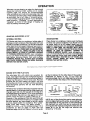
DOUBLE INSULATION Is a concept in safety, In electrlc power tools, which eliminates the need for the
usual three wire grounded power cord and grounded
sup_)ly system. Wherever there is electric current in
the tool there are two complete sets of insulation to
protect the user. All exposed metal parts are isolated
from the internal metal motor components with protecting Insulation.
GENERAL
Your electronic router is a versatile woodworking
tool which will giv e you years of trouble-free performance. It is engineered with the professional in
mind, but its ease of operation allows the amateur to
produce work which is beautiful and precise. Your
new router has advanced electronic features which
are designed to assist you In getting the maximum
use from your router. By making "the proper selections on the front panel, your router can be adjusted
to your specific routing needs. This eliminates much
of the guess work previously needed to perform a
glven job. Both the experienced and inexperienced
router users benefit, obtaining professional like
results with fewer job errors.
The electronic feature of your router introduces the
flexibility
of adjusting the motor speed to the required job Conditions. The front panel can be set according to the approximate cutter diameter you will
be using and to the hardness of the material being
cut. Your router will then run smoothly up to the
IMPORTANT -- Servicing of a tool with double insulatlon requires extreme care and knowledge of the
system and should be performed only by a qualified
service technician. For service we suggest you
return the tool to your nearest Sears Store for repair.
Always use original factory replacement parts when
servicing.
desired speed and continue to maintain
while under various loads.
this speed
Also, the best cuts are made when the cutter is fed
through the material at the proper rate. Your electronic router has "too slow" and "too fast" Indicators that will flash if the cutter is being fed too
slow or too fast. When possible, you should make
practice cuts on a scrap piece of wood to get a
"feel" of how fast to "feed" your router.
If your router should become overloaded or jammed,
then both the "too stow'" and "too fast" indicator
lights will begin flashing. If the overload condition Is
not corrected, your router will shut off. This helps
prevent the possibility of damage to the router. To
restart, release the trigger switch to its full "off"
position, wait until the indicator lights stop flashing,
then turn your router on. WARNING:
DO NOT
OVERLOAD YOUR ROUTER REPEATEDLY. ABUSE
OF THIS NATURE WILL GREATLY REDUCE THE
LIFE OF YOUR ROUTER.
RULES FOR SAFE OPERATION
WARNING -- DO NOT ATrEMPT TO OPERATE UNTIL YOU HAVE READ THOROUGHLY AND UNDERSTAND
COMPLETELY ALL INSTRUCTIONS, RULES, ETC. CONTAINED IN THIS MANUAL. FAILURE TO COMPLY CAN
RESULT IN ACCIDENTS
INVOLVING FIRE, ELECTRIC SHOCK, OR SERIOUS PERSONAL INJURY. SAVE
OWNERS MANUAL AND REVIEW FREQUENTLY FOR CONTINUING SAFE OPERATION, AND INSTRUCTING
POSSIBLE THIRD.PARTY USER.
READ ALL INSTRUCTIONS
1. KNOW YOUR POWER TOOL -pllcatlons
and
limitations
Read owner's manual carefully, Learn its ap-
as well as the specific
potential
hazards
peculiar
to
this tool.
2. GUARD AGAINST ELECTRICAL SHOCK BY PREVENTING BODY CONTACT
WITH GROUNDED SURFACES. For example: Pipes, radiators, ranges, refrigerator enclosures.
3. KEEP GUARDS IN PLACE and in working order.
4. KEEP WORK AREA CLEAN. Cluttered areas and benches invite accidents.
5. AVOID
Don'twell
useiP°werIt,
tool in clamp or wet
locationsDANGEROUS
or expose toENVIRONMENT.
rain. Keep work area
.
Page 2
RULES FOR SAFE OPERATION (Continued)
6. KEEP CHILDREN AWAY. All visitors should be kept safe distance from work
area. Do not let visitors contact tool or extension cord.
7. STORE IDLE TOOLS. When not In use, tools should be stored in dry, high or
locked-up place -- out of reach of children.
8. DON'T FORCE TOOL. It will do the job better and safer at the rate for which it
was designed.
9. USE RIGHT TOOL. Don't force small tool or attachment to do the job of a heavy
duty tool. Don't use tool for purpose not intended - for example - Don't usa
a circular saw for cutting tree limbs or logs.
10. WEAR PROPER APPAREL. No loose clothing or jewelry to get caught in moving
parts. Rubber gloves and footwear are recommended when working outdoors.
Also, wear protective hair covering to contain long hair.
11. USE SAFETY GLASSES with all tools. Also face or dust mask if' cutting
operation Is dusty.
12. DON'T ABUSE CORD. Never carry tool by cord or yank it to disconnect from
receptacle. Keep cord from heat, oil and sharp edges.
13. SECURE WORK. Use clamps or a vise to hold work. It's safer than using your
hand and it frees both hands to operate tool.
14. DON'T OVERREACH. Keep proper footing and balance at all times.
15. MAINTAIN TOOLS WITH CARE. Keep tools sharp at all times, and clean for best
and safest performance. Follow instructions for lubricating and changing accessories.
16. DISCONNECT TOOLS. Whennot in use, before servicing_ or when changing attachments, blades, bits, cutters, etc., all tools should be disconnected.
17, REMOVE ADJUSTING KEYS AND WRENCHES. Form habit of checking to see
that keys and adjusting wrenches are removed from tool before turning it on.
18. AVOID ACCIDENTAL STARTING. Don't carry piugged-m tools with finger on
switch. Be sure switch is off whenplugging in.
19. OUTDOOR USE EXTENSION CORDS.When
tool is used outdoors, use only
extension cords suitable for use outdoors, Outdoor approved cords are marked
with the suffix W-A, for example -- SJTW-A or SJOW-A.
20. KEEP CUTTERS CLEAN AND SHARP. Sharp cutters minimize stalling and kickback.
21. KEEP HANDS AWAY FROM CUTTING AREA. Keep hands away from cutters. Do
not reach underneath Work while cutter is rotating. Do not attempt to remove
material while cutter is rotating,
22. NEVER USE IN AN EXPLOSIVE ATMOSPHERE. Normal sparking of the motor
could ignite fumes.
23. INSPECT TOOL CORDS PERIODICALLY and if damaged, have repaired at your
nearest Sears Repair Center.
24. INSPECT EXTENSION CORDS PERIODICALLY and replace if damaged.
25. KEEP HANDLES DRY, CLEAN, AND FREE FROM OIL AND GREASE. Always
use aclean cloth when cleaning. Never use brake fluid, gasoline, or any Strong
solvents to clean your tool.
26. STAY ALERT. Watch what you are doing and use common sense. Do not operate tool whenyou are tired,
27. CHECK DAMAGED PARTS. Before further use of the tool, a guard or
other part that is damaged should be carefully checked to determine that it will
operate properly and perform its intended function. Check for alignment of moving parts, binding of moving parts, breakage of parts, mounting, and any other
conditions that may affect its operahon. A guard or other part that is damaged
should be properly repaired or replaced by an authorized service center unless
indicated elsewhere In this instruction manual.
28. DO NOT USE TOOL I1=SWITCH DOES NOT TURN IT ON AND OFF. Have defectire switches replaced by authorized 'service center.
29. Inspect for and remove all hails _from lumber before routitig
30. DRUGS, ALCOHOL, MEDICATION. Do not operate tool while under- the influence of drugs, alcohol, or any medication.
Page 3
-- -
+
]
nuL,-u
31.
32.
, .u+
i1+1
PUR
SAFE
OPERATION
(C0ntinu_l)
DO,NO, T USE TOOL UNDER
':BROWN:.0_T?_ORi_OTH_OW_vQLTAGE
ul/Iu.P_.
_lSO, oo not use wsth any deviC_!t'_÷('-_,l;_!_:i_-i_01wer
voltage
to change.
" ...........
..........
SAVE
THESE
CON:
supply
_
"
INSTRUCTIONS.
....
,., ,,,
-
,.. _:
_:
_. . .
.
...
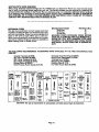
.The operation of any Router can result In forelg'n::Ob[eots being thrown
rote the.eyes, which can result Ih _eve_e:_;e:_ja_ge!:Alway$
wear
safety glasses or eye shields before €omh_encl_g _wer tool opera.
lion. we. recommend Wide Vlsl0n Safety maskforluse:_Vai; spectacles
or stanaara safety glasses, available at Si_al;_ €_._l_g_O_derOr Retail
_tOres.
.. • •
"..,.,:_i.-.::_:.:_._i_i_+_!_%_!_,:y_,
:... ' .
OPERATION
WARNING: YOUR ROUTER SHOULD NEVER BE PLUGGED IN WHEN YOU ARE._P_SEMBLING PARTS OR
MAKING ADJUSTMENTS.
FAILURE TO DO SO COULD RESULT IN ACCIDENTAL STARTING OF YOUR
ROUTER RESULTING
IN POSSIBLE SERIOUS INJURY. ALWAYS WEAR SAFF_TY :GLASSES OR
EYESHIELDS BEFORE BEGINNING POWER TOOL OPERATION.
If any parts are missing
do not operate your Router until the missing
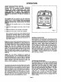
CHIP SHIELD
A clear plastic chip shield is installed on the front of
your router for protection against flying dust and
chips. The chip shield is designed to fit the front
opening of the router base as shown in figure 1. If
parts are replaced,See
Figure 1.
necessary to remove, squeeze the tabs on each end
and pull outward. To replace, squeeze the tabs at
each end, fit Into the opening, then release. DO NOT
USE ROUTER WITHOUT CHIP SHIELD PROPERLY
IN PLACE.
SWITCH
NOTE: If you forget to unlock the tdgger, the "soft"
and "1/4 Inch" Indicator lights will begin flashing
the next time you plug your router into a power
supply source. These flashing
lights serve as a
reminder that your trigger is In the "lock on" position and that your router will not start until the trigger is relased. The best precaution is to UNLOCK the
trigger after each use.
The switch of your electronic router is equipped with
a "lock
on" feature which is convenient
when
operating for extended periods of time. To lock on,
depress the trigger and engage the lock button
located on the side of the handle. To release the
lock, depress the trigger and release it. BE SURE
TOOL IS NOT IN THE "LOCK ON" POBITION
BEFORE
CONNECTING
TO POWER
SUPPLY
SOURCE.
FRONT
LOCK
POWER
DEPTH
lUSTING
RING
HAHDLE
LOCK
BUTTON
_.COLLET NUT
DEPTH
RING
-CLAMPING
WING NUT
FRONT_VIEW
REAR VIEW
Page 4
Fig. 1
OPERATION
KNOW YOUR ELECTRONIC ROUTER
Before attempting
to usa your router, familiarize
yourself with all operating features, electronic
features,
and safety requirements.
See Figure
/.WARNING:
DO NOT ALLOW FAMILIARITY WITH
YOUR ROUTER
TO MAKE
YOU CARELESS.
REMEMBER THAT A CARELESS FRACTION OF A
SECOND IS SUFFICIENT TO INFLICT SEVERE IN.
JURY.
We suggest that you practice with the electronic
features of your router before installing a cutter and
making cuts in wood. CHECK THE FOLLOWING
BEFORE CONNECTING
YOUR ROUTER TO POWER
SUPPLY:
1. Make sure the spindle lock is in the unlocked
position.
2. Make sure the trigger is not In the "lock on" position.
3. Make sure there Is not a cutter In the collet.
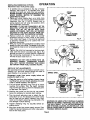
Fig. 2
4, Make sure the coIlet is inside the subbase.
Next, plug your router into power supply source
and note the indicator lights on the front panel.
See Figure 2. The "soft" and "1/4 inch" indicator
lights should belit. This tells you that your router
will operate best when cutting soft wood with 1/4
Inch steel cutters.
Grasp your router firmly with both hands and turn on.
Note the smooth acceleration of your router up to
the desired speed, with little or no twisting motion in
your hands. Once your router reaches the desired
speed, the "too slow" indicator light will begin
flashing. This tells you that there is no load on your
router. If you were actually cutting with the Router
then you would know that the rate of feed is too
slow. For best cutting results, you should then Increase the rate of feed until the indicator light quits
flashing.
NOTE: The "Too Slow" indicator Is a guide for
routing in general. In some specialized cases, such
as cutting dovetails, etc., it is necessary to feed your
router at a slower rate of feed in order to maintain
proper control. In these special situations, the "Too
Slow" indicator light will continue to flash and
should not be considered to be a problem.
You should also practice making material and cutter
size selections on the front panel. Become familiar
with the fact that these selections control speed,
which Is important when changing from one type of
wood to another or from one cutter size to another.
This controlled speed eliminates rnueh of the suddan "jerk" associated with non-electronic routers,
and increases your chances of getting smooth, burn
free cuts. The next two paragraphs describe how
material and cutter size selections are made.
MATERIAL SELECTIONS
As mentioned In the introduction, the left side of the
front panel of your electronic muter allows you to
make controlled speed selections according to the
hardness of the material being cut. Each time you
press the "select"
region above the material Indicator lights, the indicator light will shift one position. See Figure 2. The first push will change the indicator light from "soft" to "medium",
a second
push will change it from "medium"
to "hard", and a
third push will change it from "hard" to "very hard."
A fourth push will return the light tothe "soft" position. NOTE: These positions cannot be changed
with the router running.
CUTTER SiZE SELECTIONS
The right side of the front panel of your electronic
router also allows you to make controlled speed'
selections according to the size of cutter you are
using. Each time you press the "select"
region
above the cutter size Indicator lights, the indicator
light will shift one position. See Figure 2. The first
push will change the indicator light from "1/4 inch"
to "3/8 inch", a second push will change It from
"3,_8 Inch" to "1/2 inch", and a third push will
change it from "1/2 Inch" to °'3/4 inch". A fourth
push will return the light to the "1/4 inch" position.
NOTE: These positions cannot be changed with the
router running.
Page 5
INSTALLING/REMOVING
CUTIERS
Disconnect router from power supply.
OPERATION
1. A spindle lock is located on the top of motor
housing. See Figure 5. To activate lock, push
spindle lock back and slide into lock position.
NEVER ATTEMPT TO ACTIVATE SPINDLE LOCK
WHILE
ROUTER
MOTOR
IS RUNNING
OR
COASTING TO STOP.
2. Place your router upside down on a table, then
turn collet nut with wrench until lock mechanism
interlocks.
See Fig. 3.' NOTE: Spindle lock is
spring loaded and will snap into position when
lock mechanism interlocks.
WARNING; IF YOU ARE CHANGING A BIT IMMEDIATELY AFTER USE, BE CAREFUL NOT TO
TOUCH THE BIT OR COLLET WITH YOUR
HANDS OR FINGERS, THEY WILL GET BURNED
BECAUSE OF THE HEAT BUILDUP FROM CUT,
TING, ALWAYS USE THE WRENCH PROVIDED.
3. •Remove cutters by turning collet nut counter
clockwise enough to allow cutter to slip easily
from collet. See Figure 4. The collet is machined
to precision tolerances to fit cutters with 1/4"
diameter shank size.
4. With your router still upside down on table, Insert
shank of cutter into collet. The shank of your cutter should be close to but not touching bottom of
collet.
5. Tighten the :collet nut securely by turning clockwise with the wrench provided. See Fig, 4. Put
spindle lock back in unlock position. Otherwise
the interlocking
mechanism
of the spindle lock
will not let your router turn on.
COLLET
TURN TO ACTIVATE
SPtHDLE LOCK
Fig. 3
NUT
WARNING: DO NOT USE CUTTERS WITH UNDERSIZED
SHANKS.
UNDERSIZED
SHANKS
WILL NOT TIGHTEN PROPERLY AND COULD
BE THROWN FROM TOOL CAUSING INJURY.
DEPTH OF CUT ADJUSTMENTS
We recommend that cuts be made at a depth not exceeding 1/8" and that several passes be made to
reach depths of Cut greater than 1/8".
Disconnect router Irom
justing for depth of cut.
power
TO LOOSEN
COLLE'I'NUT
Fig. 4
SPINDLE LOCK
supply before ad-
1. Place the router on a flat surface, loosen clamp.
Ing Wing Nut, and turn depth adjusting ring until
cutter is inside subbase. See figure 5.
2. Turn the depth adjusting ring until tip of cutter
touches flat surface. Turn the depth indicator
ring until the zero lines Up with the indicator point
on the base. See figure 5.
3. Position the router so that the bit can extend
below the subbase for desired depth setting.
4. Turn the depth adjusting ring to obtain the de.
sired depth of cut. The distance the cutter moves
can be read on the depth indicator ring. Each
notch on the depth adjusting ring indicates 1/64
inch change in depth setting.
5. Tighten clamping
erating router.
TO TIGHTEN
COLLETNUT
wing nut securely before op-
6, Plug your router into power supply source. Then
make the desired materJal and cutter size selectIons on the front panel.
POINTS
WING NUT
Fig. 5
WARNING: BE ABSOLUTELY CERTAIN CLAMPING
WING NUT IS FIRMLY TIGHTENED. FAILURE TO DO
THIS WILL RESULT IN THE MOTOR MOVING IN.
SIDE THE BASE, CAUSING AN UNEVEN CUT, THIS
COULD CAUSE LOSS OF CONTROL RESULTING IN
POSSIBLE SERIOUS INJURY.
Page 6
OPERATION
WARNING: ALWAYS WEAR SAFETY GLASSES OR
EYESHIELDS
WHEN
USING
YOUR
ROUTER.
FAILURE TO DO SO COULD RESULT IN DUST OR
CHIPS BEING THROWN IN YOUR EYES RESULTING
IN POSSIBLE SERIOUS INJURY. IF THE CUTTING
OPERATION IS DUSTY, ALSO WEAR A FACE OR
DUST MASK.
ROUTING
See Figure 6.
For ease of operation and maintaining proper control, your router has two handles, one on each side of
the router base. After carefully making material and
cutter size selections, grasp your router and hold It
firmly with both hands as shown In Fig. 6. Turn
router on and let motor build to its full speed, then
gradually feed cutter into workpiece. Remain alert
and watch what you are doing. DO NOT operate
router when fatigued.
SPEED SELECTIONS
In general, as you move the material and cutter size
Indicators to lower positions, the router will run at
slower speeds. The slowest speed at which your
router will run is when the material indicator setting
Is at the "hard" position and the cutter size setting is
at the "3/4 inch" position. The fastest speed at
which your router will run is when the material indicator setting is at the "soft" position and the cutter size setting Is at the "1/4 inch" position.
A change from the "hard" to "very hard" material indicator position will cause an increase in the speed
of your router. This is because carbide cutters,
which cut at higher speeds than steel cutters,
should be used when cutting very hard materials.
See Helpful Hints, page 11.
RATE-OF-FEED
IMPORTANT:
In addition to selecting the proper
speed for your router, the "secret"
to professional
routing and edge shaping lies In making a careful
set-up for the cut to be made and in selecting the
proper rate of feed.
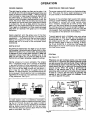
FORCE FEEDING
Clean, smooth routing and edge shaping can be
done only when the bit Is revolving at or near its proper speed and is taking very small bites to produce
tiny, cleanly severed chips. If the router is forced to
move forward too fast, the "too fast" indicator light
will begin flashing. Th_s tells you that the RPM of the
bit Is slower than normal in relation to its forward
movement - and that the bit must take bigger bites
as It revolves. "Bigger bites" means bigger chips,
and a rougher finish. Bigger chips also require more
TOO FAST
TOO SLOW
Fig. 7
Fig. 6
power - and the router motor can become overloaded so that it slows down and possibly even shuts
itself off. Under extreme forcefeeding conditions the
relative RPM of the bit can become so slow - and the
bites It has to take so large - that chips will be partially knocked off (rather than fully cut off), with
resulting, splintering and gouging of the workpiece.
See Fig. 7.
YOU SHOULD ALWAYS TRY FOR A MEDIUM RATEOF-FEED, MAKING SURE THE "TOO SLOW" INDICATOR LIGHT HAS GONE OUT AND THE "TOO
FAST" INDICATOR DOES NOT COME ON.
Your Craftsman Electronic Router is an extremely
high-speed tool (up to 25,000 rpm no-load speed),
and will make clean, smooth cuts if allowed to run
freely without the overload of a forced (too fast) feed.
What constitutes
"force-feeding"
depends upon
three things: Bit size, depth-of-cut,
and workpiece
characteristics. The larger the bit and/or the deeper
the cut, the more slowly the router can be moved forward. And, if the wood is very hard, knotty, gummy or
damp, the operation must be slowed still more.
TOO SLOW FEEDING
It Is also possible to spoil a cut by moving the router
forward too slowly. When it is advanced into the
work too slowly a revolving bit doesn't dig into new"
wood fast enough to take a bite; instead, it simply
scrapes away sawdust-like particles. Scraping produces heat, which can glaze or burn and mar the cut
-- in extreme cases, can even overheat the bit so as
to destroy its hardness.
In add(lion, It is more difficult to control a router
when the bit is scraping Instead of cutting. With
practically no load on the motor the bit will be revolving close to top rpm forths selected speed, and will
have a much greater than normal tendency to
bounce off the sides of the cut (especially, if the
wood has a pronounced grain with hard and soft
areas). As a result, the cut produced may have rlppled, instead of straight, sides. See figure 7.
You can detect "too-slow
feeding" by the flashing
light, the no-load sound of the motor, or by feeling
the "wiggle"
of the bit in the cut.
P_e7
OPERATION
PROPER FEEDING
DIRECTION
The right feed is neither too fast nor too slow. It is
the rate at which the bit is being advanced firmly and
surely to produce uniform chips -- without hogging
Into the wood to make large individual chips or, on
the other hand, to create only sawdust. If you are
making a small diameter, shallow groove in soft, dry
wood, the proper feed may be about as fast as you
can travel your router along your guide line. If the bit
_s a large one, the cut is deep, and/or the wood is
hard to cut, the proper feed may be a very slow one.
Then,. again, a cross-grain cut may require a slower
pace than an identical with grain cut in the same
workplace.
The router motor and bit revolve in a clockwise diraction. This gives the tool a slight tendency to twist
(in your hands) in a counterclockwise direction.
Good judgement with the proper
tronic feature will give best results.
experience .... by listening to the
feeling the progress of each cut.
always test cut on a scrap of the
beforehand.
use of the ElecYou will learn by
tool motor and by
If at all possible,
workpieoe wood,
DEPTH OF CUT
As previously mentiofled, the depth of cut is important because it effects the rate of feed which, In turn,
affects the quality of a cut (and, also, the possibility
of damage to your router motor and bit). A deep cut
requires a slower feed than a shallow one. A too
deep cut will cause you to slow the feed so much
that the bit will begin scraping instead of cutting.
Making a d'eep cut is never advisable. The smaller
bits -- especially those only 1/16 inch in diameter
-- are easily broken off when subjected to too much
side thrust. A large enough bit may not be broken off,
but if the cut is too deep a rough cut will result
and it may be very difficult
to guide the bit as
desired. For these reasons, we recommend that you
do not exceed 1/8 inch depth of cut in a single pass,
regardless of the bit size or the softness or condition
of the workpiece. See Fig. 8.
OF FEED AND THRUST
Because of the extremely high speed of bit rotation
during a "proper feeding" operation, there is very little kickback to contend with under normal conditions. However, should the bit strike s knot, hard
grain, etc. that would affect the normal progress of
the cutting action, there will be a slight kickback -sufficient to spoil the trueness of your cut if you are
not prepared. Such a kickback is always in the direction opposite to the direction of bit rotation.
To guard against such a kickback, plan your set-up
and direction of feed so that you will always be
thrusting the tool -- to hold it against whatever you
are using to guide the cut -- Jn the same direction
that the leading edge of the bit is moving. In short,
the thrust should be in a direction that keeps the
sharp edges of the blt continuously biting straight
into new (uncut) wood.
ROUTING
See Figure 10.
Whenever you are routing a groove, your tool travel
should be In a direction that places whatever guide
you are using at the right-hand side. When the guide
is positioned as shown in the first part of Fig. 10, tool
travel should be left to right and counterclockwise
around curves. When the guide is positioned as
shown in the second part of Fig. 10, tool travel
should be right to left and clockwise around curves.
If there is a choice, the first set-up is generally the
easiest to use. In either case, the sideways thrust
you see is against the guide.
_€_
DEPTH
UT
WIDTH
1ST.
2ND. PA_'_'_
1ST. PASS
pe-OF CUT
2N0. PASS
Fig. 8
It¢=T 8T=Uh
To make deeper cuts it is therefore necessary to
make as many successive passes as required, lowering the bit 1/8 inch for each new pass. In order to
save time, do all the cutting necessary at one depth
setting, before lowering the bit for the next pass.
This will also assure a uniform depth when the final
pass is completed. See Fig. 9.
Fig. 9
mOT_l
tU_
Flg. 10
P_e8
OPERATION
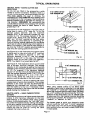
Whenever you are shaping an edge, the feed should
always be clockwise when working on an outside
(convex) edge; but should be counterclockwise
when working on an inside (concave) edge. See Fig.
11. The reason for this is that, when traveling the tool
as instructed, the bit will have a "chopping
action"
but will have a "gouging a,ction" If you reverse the
travel direction. "Chopping
is much preferable to
"gouging"
as there Is less danger of ripping, out
chips by tearing the wood grain.
,IAOrNG
_E
RD'r jTI_
_
• "€_NG"
AGI'l _
•
aOTATl_
"GOUgiNG" ,_L-rlO_l
Fig. 11
STARTING
AND ENDING A CUT
INTERNAL
ROUTING
Tilt Router and place on workplece, letting edge of
subbase contact workpiece first. Be careful not to let
Router bit contact workpieee. Turn Router on and let
motor build to Its full speed. Gradually feed cutter into workpiece until subbase Is level with workplece.
WARNING: KEEP A FIRM GRIP ON ROUTER WITH
BOTH HANDS AT ALL TIMES. FAILURE TO DO SO
COULD RESULT IN LOSS OF CONTROL LEADING
TO POSSIBLE SERIOUS INJURY. Upon completion
of cut, turn motor off and let it come to a complete
stop before removing Router from work surface.
WARNING: NEVER PULL ROUTER OUT OF WORK
AND PLACE UPSIDE DOWN ON WORK SURFACE
BEFORE THE MOTOR STOPS.
EDGE ROUTING
Place Router on workplece, making sure the Router
bit does not contact workpiece. Turn Router on and
let motor build to Its full speed. Begin your out,
gradually feeding cutter into workpiece. WARNING:
KEEP A FIRM GRIP ON ROUTER WITH BOTH
HANDS AT ALL TIMES, FAILURE TO DO SO COULD
RESULT IN LOSS OF CONTROL
LEADING TO
POSSIBLE SERIOUS INJURY. Upon completion of
cut, turn motor off and let it come to a complete stop
before removing Router from work surface. WARNING: NEVER PULL ROUTER OUT OF WORK AND
PLACE UPSIDE
DOWN ON WORK SURFACE
BEFORE THE MOTOR STOPS.
EDGING WITH THE PILOT BITS
The arbor-type bits with pilots are excellent for
quick, easy edge shaping of any worl<piece edge that
is either straight or curved at a curvature as great or
greater than the radius of the bit to be used. The pilot
prevents the bit from malting too deep a cut; and
holding the pilot firmly in contact with the workpiece
edge throughout prevents the cut from becoming
too shallow.
Whenever the workpiece thickness together with the
desired depth of cut (as adjusted by router depth set.
ting) are such that only the top part of the edge is to
be shaped (leaving at least a 1/16 in. thick uncut portion at bottom), the pilot can ride against the uncut
portion, which will serve to guide it. See Fig. 12.
However, if the workpiece is too thin and/or the bit
set too low so that there will be no uncut edge to ride
the pilot against, any extra board to act as a guide
must be placed under the workpiece. This "guide"
board must have exactly the same contour -straight or curved -- as the workpiece edge, If it is
positioned so that its edge is flush with the
workplece edge, the bit will make a full cut (In as far
as the bit radius). On the other hand, If the guide Is
positioned as shown In Fig, 12 (out from the
workpiece edge), the blt will make less than a full out
-- which will alter the shape of the finished edge.
_OIJ_t
f m
IqOUTEA
GUIDE "
TOP _DGE
SHAPfNO
w.oL__=)Ge
_._'_o
Fig. 12
NOTE: Any of the piloted bits can be used without a
pilot for edge shaping with guides, as preceding. The
size (diameter) of the pilot that Is used determines
the maximum cut width that can be made with the
pilot against the workpiece edge (the small pl!ot exposes all of the bit; the large one reduces this
amount by 1/16 inch).
Page 9
ROUTINGWITHGUIDEBUSHINGS
Whenusing TemplateGuideBushingsCat.No. 9-25079with your ElectronicRouteryou mustvisuallycenter
the bit with the bushingbefore beginning your cut. The Router subbase may be adjusted by loosening the
screws holding the subbese to the Router. Be sure clamping wing nut Is securely tightened before centering
bit In bushing. After centering bit with bushing tighten screws firmly. WARNING: FAILURE TO CENTER BIT
WITH BUSHING OR TO FIRMLY TIGHTEN SCREWS AFTER CENTERING COULD CAUSE BIT TO COME IN
CONTACT WITH BUSHING RESULTING IN SERIOUS INJURY.
Extension Cord Length
Wire Size A,W.G.
25-50 Feet
18
50-75 Feet
16
75-100 Feet
14
WARNING: CHECK EXTENSION CORDS BEFORE
EACH USE. IF DAMAGED, REPLACE IMMEDIATELY.
NEVER USE TOOL WITH DAMAGED CORD SINCE
TOUCHING THE DAMAGED AREA COULD CAUSE
ELECTRICAL SHOCK RESULTING IN SERIOUS IN.
• JURY.
EXTENSION CORDS
The use of any extension cord will cause some loss
of power, To keep the loss to a minimum and to prevent tool overheating, follow the recommended cord
sizes on the chart at right. When tool is used outdoors, use only extension cords suitable for outdoor
use and so marked. Extension ¢ords are available at
Sears Catalog Order or Retail Stores.
THE FOLLOWING
PRINTED.
RECOMMENDED
ACCESSORIES
WERE AVAILABLE AT THE TIME THIS MANUAL WAS
Dovetail Template (9 2579)
Box Joint Template (9 2580)
Butt Hinge Template (9 2575)
Butt Hinge Template (9 2564C)
Router-Crafter (9 2525C)
Multi-Purpose Router Guide (9 25179)
COMBINATION
PANEL
CUTLER
CORE 60_
BIT
VEINING
BITS
FACE
BITS
COMBINATION
STRAJGH'
BEVEL
C.urrER
Template Guide Bushings (9 25079)
Rout-A-Form Pantograph (9 25183)
Template Set (9 25182)
Sharpening Kit (9 66501)
Carrying Case (9 1470)
Full View Router Base (9 25086)
ARBORS
COVE
OOEE
)OVETAIL
HINGE
MORTISlN(
BIT
CUTTER
BITS
RABBET
a/_"
BIT
=ss_
SIT
2_1;P2-3/6"
, _I_-_/2"
I "2S_P/8-3/$"
t "2_,_75-1/2"
eEAD
QUARTER.
ROUND
BITS
:zBrdl6.
I/2"
bP.GROOVE
CHAMFER
255eS.1/lS"
;_111+41'_1
$"
;ZSB;J,I/e"
_S21-1/4"
,_h522.3/IP
ZSM_l/2"
aJt421kS14"
DOUBI.E F.+NQ
ZSS4S4_', I_"
' -lfss'llUlt'_
V-GROOVE
I
!,
|
FOR
"2_1!
VENEER
pA_-t/4"
"2M_J-II4 _
"2_25-B/111"
• _ll2_vir
+
• P.,_l_f.1t2"
25BD
STRAIGHT
"2511;I
LsVI_
"211,412
CAUTION: The use of attachments
I/_"
_ss,_I/,P
:m,_:_l._/=-
ROMAN C
P,
ss+I
CHAMFER
m;s+z.,s,,_,J,
BIT
I "cxeme neeeo errs
or accessories
Page 10
21Lce_I/_f"
=/e"
255M1.1/4"
_e
2554_1-1/L_
"=s._s-I/a"2ss4tts-I/2"
1
not listed above might be hazardous,
Win1 z
EAt._
BEARING8
TYPICAL
OPERATIONS
HELPFUL HINTS - MAKING CUTTER SIZE
SELECTIONS
AS you can see listed in the accessories, a wide
variety of cutters is available. Therefore, there is a
variety of sizes, grooves, curves and angles involved.
This often creates the need to estimate the
AVERAGE CUTTING DIAMETER when making cutter
size selections on the front panel. The following examples Illustrate how to estimate, the average cutting diameter. REMEMBER: We recommend that
cuts be made at a depth not exceeding 1/8" and that
several passes be made to reach depths of cut
greater than 1/8"
5/16" DEPTH OF CUT
AND AVERAGE DIA.
_-5/8 MAXIMUM DIA.
Fig. 13
See Figure 13. In this illustration a V-groove cutter is
being used to make a 5/16" deep cut. To find the
average
cutting
diameter,
add the maximum
diameter (5/8") to the minimum diameter (0), then
multiply by 1/2. The average diameter of the cut
equals 5/16". Since 5116" lies between the "1/4
inch" and "3/8 inch" position on the front panel,
either could be used. Difficulty in controlling, difficulty in cutting, material hardness, etc. are factors
which can be used In determining which position to
select. For example, if the material was difficult to
cut, then the "3/8 inch" position would probably be
best since the cutting speed will be slower.
\3iff'AVEllAGE
See Figure 14. In this illustration the V-groove cutter
is being used to make a cut with a 3/4" maximum
diameter.
The m_ximum diameter
is 3/4", the
minimum diameter is still 0", and the average
diameter Is now 3/8". In this case, the "3/8 Inch"
position would be the best cutter size selection.
NOTE: Your depth of cut would also be 3/8".
""---3/4" _.XIMuM
HELPFUL HINTS _ USING CARBIDE TIPPED
CUTTERS
Since carbide cutters cut at higher speeds than steel
cutters, it often becomes necessary for the front
panel settings to be different while using carbide
cutters. As mentioned earlier, the "very hard" position under the material indicator setting was designed for using carbide cutters when cutting materials
that are too hard for steel cutters. However, carbide
cutters can also be used for cutting the same
materials that steel cutters cut.
DIA.
Fig. 14
See Figure 15. This illustration shows a cove cutter
with a non-zero minimum
diameter. The average
diameter Is still computed by adding the maximum
diameter to the minimum diameter, then multiplying
by 1/2. For example, If the maximum
diameter
equals 112" and the minimum diameter equals 3/8",
then the average diameter equals 7/16" (1/2 is the
same as 4/8, therefore, 4/8" + 3/8 = 7/8", 7/8" x
1/2 --. 7/16"). Either the "3/8 inch" or "1/2 Inch"
position could be selected on the front panel.
As mentioned earlier, it is best to make a trial cut on
a scrap piece of wood where possible. The average
diameter of the cutter can also be determined
by
measuring
the maximum and minimum diameter
from the widths of a trial cut. If necessary, then a
change or correction in the cutter size can be made
before making the finished cut.
DL4,
•
ij
--3/8"MINIMUM
Jl
_._
DUL
1/2" MAXIMUM
DUL
Fig. 15
When using carbide cutters to but these softer
materials, a good rule to remember Is to set either
the "material"
or "cutter size" iridicator one position
above that recommended
for steel cutters. For example, a 1/2" carbide cutter should have the "3/8 inch"
selection on the front panel. If a 1/4" carbide cutter
is being used then the material indicator should be
moved up one position. For example, from "hard" to
"medium",
or "'medium" to "soft".
The fastest speed at which your electronic router
will run is with the "soft" and "1/4 Inch" selections
on the front panel. This will be the fastest speed for
both carbide cutters and steel cutters (25,000 RPM,
no-load speed).
Page 11
MAINTENANCE
WHEN SERVICING
USE ONLY IDENTICAL
REPLACEMENT
PARTS
PROPER CARE OF CUTTERS
Get faster more accurate cutting results by keeping
cutters clean and sharp. Remove all accumulated
pitch and gum from cutters after each use.
When sharpening cutter, sharpen only the Inside of
the cutting edge. Never grind the outside diameter.
Be surewhen sharpening the end era cutter to grind
the clearance angle the same as originally ground.
A cutter sharpening kit (cat. #66501) is available from
Sears Catalog Order or Retail Store. NOTE: WHEN
SHARPENING CUTTERS WITH YOUR ELECTRONIC
ROUTER, MAKE THE "SOFT"
AND "t/4
INCH"
SELECTIONS ON THE FRONT PANEL.
,j"
Fig. 16
PROPER CARE OF COLLET
From time to time, it also becomes necessary to
clean your collet and collet nut. To do so, simply
remove collet nut from collet and clean the dust and
chips that have collected. Then return collet nut to
its original position.
SWITCH REPLACEMENT
Disconnect router from power supply.
SWITCH REPLACEMENT IS AS FOLLOWS:
1. Remove screws (A) nuts !B) and handle covers ((3).
See Figure 16,
2. Note location of grommet (D) in handle end how
each lead Is connected to switch.
3. Remove leads from switch by inserting a 1/32"
diameter pin or nail into switoh lead receptacle as
shown in figure 16 and pulling on the lead.
Remove nail orpln with a twisting, pulling motion.
4, Make sure grommet (D) is on cord and push each
lead as far as possible into proper receptacle in
switch,
5. Locate switch in handle and place leads so they
won't be pinched when handle cover is replaced.
6. Make sure grommet (D) is in place and replace
handle cover, screws and nuts.
GENERAL
WARNING: ONLY THE PARTS SHOWN ON PARTS
LIST, PAGE FIFTEEN,
ARE INTENDED
TO BE
REPAIRED OR REPLACED BY THE CUSTOMER. ALL
OTHER PARTS REPRESENT AN IMPORTANT PART
OF THE DOUBLE INSULATION
SYSTEM AND
SHOULD BE SERVICED ONLY BY A QUALIFIED
SEARS SERVICE TECHNICIAN.
Avoid using solvents when cleaning plastic parts.
Most plastics are susceptible to various types of
commercial solv(tnts and may be damaged by their
use. Use clean cloths to remove dirt, carbon dust,
etc. WARNING: DO NOT AT ANY TIME LET BRAKE
FLUIDS, GASOLINE,
PENETRATING
OILS, ETC.
COME IN CONTACT WITH PLASTIC PARTS. THEY
CONTAIN
CHEMICALS
THAT
CAN
DAMAGE
AND/OR DESTROY PLASTIC.
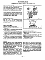
LIGHT BULB REPLACEMENT
Disconnect router from power supply.
1. Remove cutter from router. Adjust router to max.
Imum height.
2. Remove screws (A) and subbase (B). See Figure
17.
3. Remove screws (C) and work light lens (D).
4. With bulb pointing toward you, push bulb In and
turn to the left to remove.
5. Reassemble all parts.
When electric tools are used on fiberglass boats,
sports cars, etc., it has been found that they are subject to accelerated wear and possible
premature
failure, as the fiberglass
chips and grinc!lngs are
highly abrasive to bearings, brushes, commutators,
etc. Consequently it is not recommended that this
tool be used for extended work on any fiberglass
material. During any use on fiberglass it is extremely
important that the tool Is cleaned frequently byblowIng with an air jet. ALWAYS WEAR
SAFETY
GLASSES OR EYESHIELDS BEFORE BEGINNING
THIS OPERATION.
Page 12
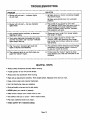
TROUBLESHOOTING
SOLUTION
PROBLEM
1, Router will not start -do not flash.
1. (a)Maka sure your router is properly plugged
Into power supply.
indicator lights
(b) Make sure spindle lock is in unlocked
position.
2. Router will not start -- top two indicator
lights flash.
J
.,,
The switch of your router is not In the
"off" position, NOTE: Any time your router is
disconnected from power supply and the
switch is locked In the "lock on" position,
this condition will exist.
2.
J
3. Any unusual router condition, or abnormal
flashing of lights.
.
4. Turn the trigger switch to Its full "off"
position, walt a few seconds, then restart
your router and continue routing at a slower
rate of feed.
4. Your router becomes overloaded and shuts
off. The "too slow" and "too fast" Indicator
lights begin flashing:
5. The "too slow" Indicator light does not
flash or flashes inconsistently.
.
This condition exists because of low voltage
conditions in the power supply. Continue
to use your router as normal.
6. Firmly press the "select"
region to clean
away sawdust, etc. that has collected on the
contacts.
6. The indicator lights do not shift when you
push the "select"
region.
HELPFUL
• Always clamp workplace securely
DisconneCt your router from power supply,
then plug it In again.
HINTS
before routing,
• A safe operator is one who thinks ahead.
• Always wear eye protection when routing.
• Make set-up adjustments
• Keep cutters
carefully, Then double check. Measure twlce and out once.
clean and properly sharpened.
• Don't Tat familiarity
make.you careless.
• Study all safety rules and do the job safely.
• NEVER place your hands in jeopardy,
• Make certain clamps can't
• Test difficult
loosen while in use.
set-ups on scrap -- Don't waste lumber.
• Plan each operation before you begin.
• THINK SAFETY BY THINKING
AHEAD.
Page 13
.........
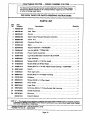
CRAFTSMAN
ROUTER
--
MODEL
NUMBER
315.17500
....
1
_----25
9
6
11
1
16
20
O=_= 14
13
CRAFTSMAN
ROUTER
--
MODEL
NUMBER
315.17500
|
The Model Number will be found on a plate attached to the End Cap. Always
mention the Model Number' in all correspondence regarding your ROUTER
or when ordering repair pads.
I
I
t
SEE BACK PAGE FOR PARTS
ORDERING
INSTRUCTIONS
I
PARTS LIST
Key
No.
Part
Number
Description
Quantity
1
989935-003
Wrench ......................................................
1
2
990379-001
Data Plate ....................................................
1
3
990376-001
Pointer .......................................................
1
4
969652-002
Depth Adlust Ring and Indicator Assembly .........................
1
S
989985-003
Coliet
1
6
623615.002
Clamping Wing Nut ............................................
7
612442.434
Base ....................................
8
623166-002
Square Head BOlt "'STD522507 ..................................
1
9
706404-007
Hex Nut (#8-32) "'STD541008
4
10
611457-00O
Power Handle Assembly ........................................
1
11
610951-002
Light Bulb (Standard Automotive Bulb #1004) .......................
1
12
610930.001
Light Housing......
1
13
606066-0O2
"Screw (#10-32 x 11/16 Pan Head) ................................
4
14
614658-006
"Screw (#8-32 x 5/8 Pan Head) ...................................
4
16
616081-014
"Screw (#8-18 x 11/16 Pan Head Thread Cutting) '*STD610807..
16
623814-005
Switch .......................................................
1
-17
610946,001
Work Light Lens ................................................
1
18
989684-001
19
812191-004
20
623863-001
Nut ....................................................
1
............
. ........
....................................
..........................................
.
"Screw (#6-32 x 114 Thread Forming) ..............................
Subbase ......................................................
*Screw (#10-32 x 114 Pan Head) ..................................
......
1
4
1
1
3
21 ' 606688-001
Chip Shield ...................................................
1
22
990374.001
Logo Plate ....................................................
1
23
726678-002
Set Screw (//8-32 x 7/16 Hex Socket, Self Locking) ...................
1
24
611458-000
Handle Assembly ..............................................
1
25
623782,001
Grommet .....................................................
1
612547.213
Owner's Manual
NOTE "A" _ The assembly shown represents en Important part of the Double Insulated System. TO avoid the pOsslblf|tlt
ot atteratlon or damage to the System, service should be porlormed by your nearest Seers Repair Center, Contact
your nearest Catalo9 Order or Retail Store.
"Standard
"'Available
Hardware Item -- May Be Purchased
From DaY. 98 -- eour©o 980.00
Locally
Page 15
l Sears
OWNERS
MANUAL
CRRFTSMRN"
LECTRONIC
ROUTER
DOUBLE INSULATED
SERVICE
MODEL NO.
315.17500
HOW TO ORDER
REPAIR PARTS
Now that you have purchased
your Router, should a
need ever exist for repair parts or service,
simply
contact
any Sears Service Center and most Sears,
Roebuck and Co, stores. Be sure to provide all pertinent facts when you call or visit,
The model number of your Router will be found on
the plate attached to the motor housing.
WHEN ORDERING
THE FOLLOWING
REPAIR PARTS,
INFORMATION:
ALWAYS
• PART NUMBER
• PART DESCRIPTION
* MODEL NUMBER
315.17500
• NAME OF ITEM
Router
GIVE
All parts listed may be ordered from any Sears Service Center and most Sears stores.
If the parts you need are not stocked locally, your
order will be electronically
transmitted
to a Sears
Repair Parts Distribution Center for handling.
SEARS, ROEBUCK AND CO., Dept. 698/731A,
Sears Tower, Chicago,
IL 60684