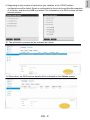
1
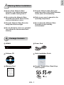
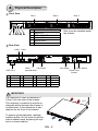
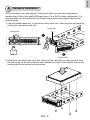
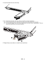
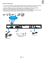
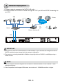
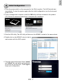
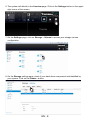
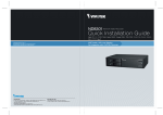
NR8401
Network Video Recorder
Quick Installation Guide
Rack Mount Design • Compatible with VAST •
Full Integration with VIVOTEK Cameras
P/N:625020201G Rev. 1.1
All specifications are subject to change without notice.
Copyright c 2013 VIVOTEK INC. All rights reserved.
VIVOTEK INC.
6F, No.192, Lien-Cheng Rd., Chung-Ho, New Taipei City, 235, Taiwan, R.O.C.
|T: +886-2-82455282| F: +886-2-82455532| E: [email protected]
VIVOTEK Netherlands B.V.
Busplein 36, 1315KV, Almere, The Netherlands
|T: +31 (0)36 5389 149| F: +31 (0)36 5389 111| E: [email protected]
VIVOTEK USA, INC.
2050 Ringwood Avenue, San Jose, CA 95131
|T: 408-773-8686| F: 408-773-8298| E: [email protected]
English
Warning Before Installation
Power off the Network Video
Recorder if you detect abnormal
smell or smoke coming from it.
Keep the Network Video Recorder
away from water. If the Video Recorder
is wet, power off immediately.
Do not place the Network Video
Recorder around the heat sources,
such as television or oven.
Refer to your user's manual for the
operating temperature.
Keep the Network Video Recorder
away from direct sunlight.
Do not place the Network Video
Recorder in high humidity
environments.
Do not attempt to remove or uninstall
the software on the mounted flash
memory.
1
Package Contents
NR8401
Power Cord
Software CD
Quick Installation Guide
5 1 0 0 0 02 2 1 G
Screws, Chassis Ears, Bezel Keys,
and Foot pads
Warranty Card
x16
EN - 1
2
Physical Description
Front View
1
2
3 4
Disk 1
5
1
2
3
4
5
6
6
Disk 2
Power button and LED
Status LED
HDD activity LED
Restore Default button
Backup button
USB
Disk 3
Disk 4 can be installed inside
the chassis.
Rear View
LAN2
LAN1
Fan Outlet
Fan Outlet
GPIO
terminal block
USB 1 & 2
1
DO+ (12V)
6
DI2-
11
Power button
2
DO-
7
DI3+
12
GND
RS232_TX
3
DI1+
8
DI3-
13
4
DI1-
9
DI4+
14
RS232_RX
5
DI2+
10
DI4-
15
GND
16
Power Switch
Power Cord
Socket
GND
IMPORTANT:
It is important to leave a clearance of
10cm to the rear side of the chassis.
The clearance is required to ensure an
adequate airflow through the chassis to
ventilate heat. A 5cm clearance is also
required on the front of the chassis.
10cm
To ensure normal operation, maintain
ambient airflow. Do not block the airflow
around chassis such as placing the system in a closed cabinet.
5cm
EN - 2
English
3
Hardware Installation
SATA hard disk(s) are user-supplied. The network video recorder can readily accommodate most of the off-the-shelf SATA hard drives. For a RAID volume configuration, it is
recommended you use hard drives of the same model featuring the same capacity and
rotation speed.
1.Use the included bezel key to unlock the rotary bezel lock. Open the drive bay bezel by
pushing the door latch to the side.
Door Latch
Bezel Lock
1
2
Bezel Lever
2.Install your hard disk to the drive tray. Gently put the hard disk into drive tray with its label side facing up and the connector side towards the inside of the chassis. Secure the
hard disk by driving screws from the bottom.
EN - 3
3.Insert the hard drive into drive bay.
4.4-1. P
ush the hard drive into bay until you feel the contact resistance.
4-2. C
lose the bezel lever to connect the hard drive to the back-end connector.
4-3. You should always lock the drive bezel when the drive bay is populated. This ensures the hard drive is securely installed.
1
2
5.Repeat the process above to install more hard drives.
EN - 4
English
Interface Connections
1 & 2. Connect CAT5e or better-quality Ethernet cables to cameras via a local, switched
network, or clients through the Internet. Refer to next page for more information.
3.Connect USB devices such as USB optical drive (formatted in FAT format) or UPS.
4.Connect external digital input/output devices to the GPIO teminal block.
5.Make sure the power switch on the rear panel is in the Off (O) position. Connect the supplied power cord to the power mains (100-240V AC, 3-1.5A, 50~60Hz).
Router
LAN/WAN
1
3
2
5
4
Power cord
DI/DO devices
USB devices
EN - 5
4
Network Deployment
1.Connect network cameras to the NVR’s LAN ports.
2.Internet access to the NVR is made through the TCP port 80 and RTSP streaming via
port 554.
16x
Clients
Router
Internet
Router
Switch
Router / Wireless AP
LAN
IMPORTANT:
1. The NVR only receives H.264 and MPEG-4 video streams. If your cameras are configured to deliver
MJPEG streams, please change their video stream configuration.
2. The maximum recording bandwidth is 96Mbps using single disks or RAID0/1, and 48Mbps using a
RAID5 volume.
NOTE:
1. The two LAN ports can be configured into the same or different subnets, or into a failover or loadsharing trunk group.
2. Client computers should support IE8 browser at a minimum of 1280x960 resolution or higher.
EN - 6
English
5
Initial Configuration
1.Press the power switch on the rear panel to the ON (I) position. The NVR should start
immediately. To start the system again after the initial configuration, use the front panel
power button.
2.From a management computer, install the IW2 utility software included in the product
CD. Follow the onscreen instructions to complete the installation.
3.Start the IW2 utility. The IW2 utility will discover the NR8401 located in the same subnet.
4.Double-click on the NR8401 entry to start a
web session with the NVR system.
5. The login page will prompt. Enter "admin"
and "admin" as user name and password
for access for the first time. Click Login to
begin your configuration.
EN - 7
6.The system will default to the Liveview page. Click on the Settings button on the upper
right corner of the screen.
7.On the Settings page, click on Storage > Volume to access your storage volume
configuration.
8.On the Storage settings page, check if your hard drives are present and identified by
your system. Click on the Create... button.
EN - 8
10. The initialization process will be indicated as follows.
11. When done, the RAID volume details will be indicated on the Volume screen.
EN - 9
English
9.Depending on the number of hard drives you installed, a list of RAID volume
configurations will be listed. Select a configuration's check circle and the disk members
of a volume, and then click OK to continue. The initialization of a RAID volume will take
several minutes.
12. Click on Camera > General on the menu tree to open the camera settings page. Click
on the Search button to locate cameras installed in the subnet.
13. Cameras on the network will be listed. Click on the + button on the far left to enlist
them into your configuration. Click OK when done on this page. Click Save when you
return to the Camera page.
14. By default, cameras are configured to record all streaming at all time. You can change
the recording settings in Camera > Schedule.
15. Refer to your User Manual for more operation and configuration details.
EN - 10
NR8401
Network Video Recorder
Quick Installation Guide
Rack Mount Design • Compatible with VAST •
Full Integration with VIVOTEK Cameras
P/N:625020201G Rev. 1.1
All specifications are subject to change without notice.
Copyright c 2013 VIVOTEK INC. All rights reserved.
VIVOTEK INC.
6F, No.192, Lien-Cheng Rd., Chung-Ho, New Taipei City, 235, Taiwan, R.O.C.
|T: +886-2-82455282| F: +886-2-82455532| E: [email protected]
VIVOTEK Netherlands B.V.
Busplein 36, 1315KV, Almere, The Netherlands
|T: +31 (0)36 5389 149| F: +31 (0)36 5389 111| E: [email protected]
VIVOTEK USA, INC.
2050 Ringwood Avenue, San Jose, CA 95131
|T: 408-773-8686| F: 408-773-8298| E: [email protected]