1
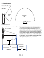
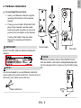
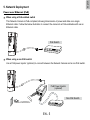
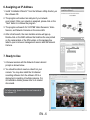
CC8130
Compact Cube
Network Camera
Quick Installation Guide
English
繁中
Nederlands
P/N:625022000G Rev. 1.0
6F, No.192, Lien-Cheng Rd., Chung-Ho, New Taipei City, 235, Taiwan, R.O.C.
|T: +886-2-82455282| F: +886-2-82455532| E: [email protected]
VIVOTEK Netherlands B.V.
Busplein 36, 1315KV, Almere, The Netherlands
|T: +31 (0)36 5389 149| F: +31 (0)36 5389 111| E: [email protected]
日本語
Français
Español
Deutsch
Indonesia
1MP • Stylish Design • Panoramic View
All specifications are subject to change without notice.
Copyright c 2013 VIVOTEK INC. All rights reserved.
VIVOTEK INC.
簡中
Dansk
VIVOTEK USA, INC.
2050 Ringwood Avenue, San Jose, CA 95131
|T: 408-773-8686| F: 408-773-8298| E: [email protected]
Português
Italiano
Türkçe
Polski
Русский
Česky
Svenska
Warning Before Installation
Power off the Network Camera as soon as smoke or
unusual odors are detected.
Do not place the Network Camera on unsteady
surfaces.
Do not insert sharp or tiny objects into the Network
Camera.
Keep the Network Camera away from water. If
the Network Camera becomes wet, power off
immediately.
Do not touch the Network Camera during a
lightning storm.
Do not place the Network Camera in high humidity
environments.
1. Package Contents
CC8130
Screws / Mount bracket
Quick Installation Guide / Warranty Card
Software CD
2. Physical Description
Outer View
Camera bracket
Reset button
Lens
Microphone
LED
RJ-45 release
button
3. Considerations
Camera View Coverage
Side View
Vertical:
100º
Horizontal:
180º
Top View
Installation Concern
The camera is designed to capture human activities in
a near-hemispheric field of view, at a place such as a
cashier or bank counter. Due to the optical characteristics
of wide-angle lens, image quality decreases as distance
from an object increases. It is therefore recommended to
install the camera within 3 meters or closer to the objects
of your interest. The focus center should also be aligned
with objects of importance, say, human faces.
15° tilt bracket
1.6~1.8m
3m
Recognition
Perception
2m
EN - 2
English
4. Hardware Installation
Connecting Ethernet Cable
1. Insert your Ethernet cable through the
opening at the bottom of the camera
bracket.
2. If using a round cable: When the RJ-45
plug is fully inserted, use the roundhead screw with a washer to secure its
position from the bottom of the bracket.
If using a flat cable: Pass the cable
through the opening and attach to
camera.
IMPORTANT:
Round cable
Record the MAC address before installing the
camera.
Flat cable
NOTE:
To detach a camera, remove the retention screw
from the bottom, and insert a straightened paperclip
into the release button to press on the RJ-45 locking
tab.
NOTE:
It is recommended to use an Ethernet cable that
comes without the strain relief boot. You can remove
the boot if your cable comes with one.
Strain relief boot
EN - 3
Mounting the Network Camera - Wall Mount
1. You can install the camera to a vertical surface by driving screws through the holes shown below.
2. You may also install the bracket to a 4” x 2” utility box (as outlet or switch socket).
3. Another option is using the 15° tilt bracket so that the camera can be installed to an over-looking
position. Attach the bracket to a utility box, and then secure the mount bracket. You can route the
cable through the hole in the middle.
4. Attach a rubber seal pad to the bottom of the mount bracket.
5. Install the camera. Make sure the RJ-45 connector is properly connected.
1
2
3
15° tilt bracket
4
5
EN - 4
English
5. Network Deployment
Power over Ethernet (PoE)
When using a PoE-enabled switch
This Network Camera is PoE-compliant, allowing transmission of power and data via a single
Ethernet cable. Follow the below illustration to connect the camera to a PoE-enabled switch via an
Ethernet cable.
PoE Switch
POWER
COLLISION
1
2
3
4
LINK
RECEIVE
PARTITION
5
When using a non-PoE switch
Use a PoE power injector (optional) to connect between the Network Camera and a non-PoE switch.
PoE Power Injector
(optional)
Non-PoE Switch
POWER
EN - 5
COLLISION
1
2
3
4
5
LINK
RECEIVE
PARTITION
6. Assigning an IP Address
1. Install “Installation Wizard 2” from the Software Utility directory on
the software CD.
2. The program will conduct an analysis of your network
environment. After your network is analyzed, please click on the
“Next” button to continue the program.
3. The program will search for VIVOTEK Video Receivers, Video
Servers, and Network Cameras on the same LAN.
4. After a brief search, the main installer window will pop up.
Double-click on the MAC address that matches the one printed
on the camera label or the S/N number on the package box
label to open a browser management session with the Network
Camera.
172.16.7.13
0002D10766AD
7. Ready to Use
1. A browser session with the Network Camera should
prompt as shown below.
2. You should be able to see live video from your
camera. You may also install the 32-channel
recording software from the software CD in a
deployment consisting of multiple cameras. For
its installation details, please refer to its related
documents.
For further setup, please refer to the user's manual on
the software CD.
EN - 6
PZ71X2
CC8130
CC8130
Compact Cube
Network Camera
Quick Installation Guide
English
繁中
Nederlands
P/N:625022000G Rev. 1.0
6F, No.192, Lien-Cheng Rd., Chung-Ho, New Taipei City, 235, Taiwan, R.O.C.
|T: +886-2-82455282| F: +886-2-82455532| E: [email protected]
VIVOTEK Netherlands B.V.
Busplein 36, 1315KV, Almere, The Netherlands
|T: +31 (0)36 5389 149| F: +31 (0)36 5389 111| E: [email protected]
日本語
Français
Español
Deutsch
Indonesia
1MP • Stylish Design • Panoramic View
All specifications are subject to change without notice.
Copyright c 2013 VIVOTEK INC. All rights reserved.
VIVOTEK INC.
簡中
Dansk
VIVOTEK USA, INC.
2050 Ringwood Avenue, San Jose, CA 95131
|T: 408-773-8686| F: 408-773-8298| E: [email protected]
Português
Italiano
Türkçe
Polski
Русский
Česky
Svenska