1
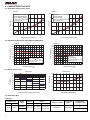
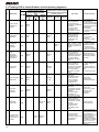
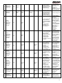
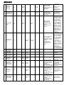
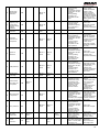
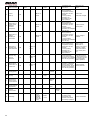
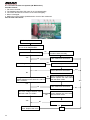
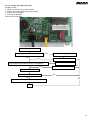
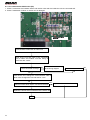
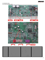
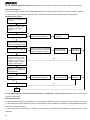
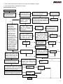
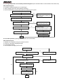
TECHNICAL MANUAL 2013 SPLIT MONO DC INVERTER MODELS BDS28A BDS35A This manual has been created for informative purpose. The company declines every responsibility for the results of projecting or installation based on the explanations and the technical specifications given in this manual. Is besides forbidden the reproduction under any form of the texts and of the figures contained in this manual. Serie / Series / Serie / Serie TECHNICAL MANUAL MONO DC INVERTER Emissione / Issue Ausgabe / Emission 04 - 2013 Sostituise / Supersade Ersetzt / Remplace - Catalogo / Catalogue / Katalog / Catalogue MTE01028D2505-00 2 Index 1. SPECIFICATIONS ......................................................................................................................................4 2. CHARACTERISTICS DATA........................................................................................................................6 2.1 Operation characteristic curve ..................................................................................................................6 2.2 Capacity variation ratio according to temperature ....................................................................................6 2.3 Noise criteria curve ...................................................................................................................................6 2.4 Operation data ..........................................................................................................................................6 3. DIMENSIONS ...........................................................................................................................................7 3.1 Indoor units ...............................................................................................................................................7 3.2 Outdoor units ............................................................................................................................................7 4. REFRIGERANT DIAGRAM ......................................................................................................................8 5. ELECTRICAL CIRCUIT DIAGRAM ...........................................................................................................9 5.1 Indoor units ...............................................................................................................................................9 5.2 Outdoor units ............................................................................................................................................9 6. PRINTED CIRCUIT BOARD.....................................................................................................................10 6.1 Indoor units .............................................................................................................................................10 6.2 Outdoor units ..........................................................................................................................................10 7. CONTROL FUNCTIONS .........................................................................................................................11 7.1. Temperature parameters .......................................................................................................................11 7.2. Basic functions.......................................................................................................................................11 8. TROUBLESHOOTING ............................................................................................................................15 8.1 Malfunction diagnosis should be performed as below procedure...........................................................15 8.2 Confirmation ...........................................................................................................................................15 8.3 Flashing LED of Indoor/Outdoor unit and primary judgement ................................................................16 8.4. How to check simply the main parts ......................................................................................................21 Appendix 1: form for indoor/outdoor unit’s ambient sensor numerical value of resistance .........................32 Appendix 2: form for indoor/outdoor unit’s tube temperature sensor numerical value of resistance ..........33 Appendix 3: form for indoor/outdoor unit’s air exhaust temperature sensor numerical value of resistance..34 3 1. SPECIFICATIONS Models of indoor units BDS28A BDS35A Rated voltage 220-240V ~50Hz Total capacity Cooling Power input Rated current S.E.E.R. Total capacity Heating kW 2,5(0,7 ~ 4,4) 3,5(0,7 ~ 4,5) Btu/h 8,53(2,3 ~ 15,00) 11,9(2,3 ~ 15,3) W 520 900 A 2,3 4,0 W/W 7,5-A++ 7-A++ kW 2,7(0,7 ~ 4,8) 3,5(0,7 ~ 5,5) Btu/h 9,3(2,4 ~ 16,3) 12,4(2,4 ~ 18,7) Power input W 565 895 Rated current A 2,37 7,5 S.C.O.P. Air flow volume (SH/H/MH/M/ML/L/SL) Dehumidifying volume W/W 4,6 – A++ 4,6 – A++ m³/h 730/670/610/530/460/410/380 770/670/610/530/460/410/380 l/h 0,8 1,4 1350/1070/1000/900/800/700/500 Fan motor cooling speed (Max - Min) r/min 1300/1050/1000/900/800/700/500 Fan motor heating speed (Max - Min) r/min 1300/1150/1080/1030/980/900/850 1350/1150/1080/1030/980/900/850 Output of fan motor W 15 15 Fan motor capacitor μF / / Fan motor RLA A Fan type - piece Evaporator Indoor unit Diameter x length mm Φ98 x 662 Φ98 x 662 Aluminium Fin-copper Tube Pipe diameter mm Φ7 Φ7 Row-fin gap mm 2-1.5 2-1,5 Coil length x height x width (l x H x L) mm 662 x 25,4 x 305 662 x 25,4 x 305 MP24HA/MP24HB/MP24HC MP24HA/MP24HB/MP24HC 2,4 2,4 Output of swing motor Fuse W A 3,15 3,15 Sound pressure level dBA 36/32/21 36/32/21 Sound power level dBA 46/42/31 46/42/31 Dimension (W/H/D) mm 866 x 292 x 209 866 x 292 x 209 Dimension of package (W/H/D) mm 945 x 377 x 297 945 x 377 x 297 kg 11/14 11/14 Net weight/gross weight Models of outdoor units Compressor manufacturer/trademark Compressor model BDS28A BDS35A SANYO Compressor oil Compressor type C-6RZ110H1A C-6RZ110H1A FV50S FVC 68D / RB 68EP ROTARY ROTARY A 33,00 33,00 Compressor RLA A 4,59 4,59 Compressor power input W 800 800 L.R.A. Overload protector 1NT11L-3979 Throttling method 1NT11L-3979 Electronic expansion valve Starting method 16°C ~ 30°C Working temperature range (°C) -20°C ~ 48°C Condenser Outdoor unit 0,07 Cross flow - 1 Evaporator type Swing motor model 4 0,07 Cross flow - 1 Condensor type Aluminium Fin-copper Tube Pipe diameter mm Φ7,94 Φ7,94 Rows-fin gap mm 2,5-1,5 2,5-1,5 mm 763 x 57 x 550 730 x 38.1 x 508 Fan motor speed Coil length (l) x height (H) x width (L) rpm 850/750/600 850/750/600 Output fan motor W 40 40 Fan motor RLA A 0,23 0,23 Fan motor capacitor Air flow volume of outdoor unit μF / / m³/h 2000 2000 Fan type-piece Axial-flow Fan diameter mm Φ445 Defrosting method Climate type T1 T1 I I IP24 IP24 Mpa 3,8 3,8 Mpa 1,2 1,5 Isolation Connecting pipe Φ445 Automatic Defrosting Moisture protection Permissible excessive operating pressure for the discharge side Permissible excessive operating pressure for the suction side Sound pressure level dB(A) 49/-/- 50/-/- Sound power level dB(A) 59/-/- 60/-/- Dimensions (WXHXD) mm 906 x 596 x 378 906 x 596 x 378 Dimension of package (L/W/H) mm 948 x 420 x 645 348 x 420 x 645 Net weight/gross weight kg 43/47 43/47 Refrigerant charge (R410A) kg 1,3 1,3 Length m 5 5 Gas additional charge Outer diameter Max distance g/m 20 20 Liquid pipe mm Φ6 Φ6 Gas pipe mm Φ9,52 Φ9,52 Height m 10 10 Length m 15 20 The above data of specifications are subject to change without prior notice. Please refer to the actual data specified on the nameplate of the unit. Note: Test conditions: Standard condition Indoor side state Dry bulb temp. °C Outdoor side state Wet bulb temp. °C Dry bulb temp. °C Wet bulb temp. °C Rated cooling 27 19 35 24 Rated heating 20 15 7 6 3) Microphone at a distance of 1m from the unit. Approximate calculation from Sound Pressure Level to Sound Power Level: - Average Sound Pressure Level L p =10*lg [1 / 2 * (100.1* L + 10 0.1* L P1 P2 ]. LP 1 : Sound pressure level of front test point. L P 2 : Sound pressure level of side test point for indoor unit LP 1 , L P 2 . - Approximate Sound Power Lever LW = L p +10. 5 2. CHARACTERISTICS DATA 2.1 Operation characteristic curve Heating Cooling 10 Condition Indoor:DB27 WB19 8 Outdoor:DB35 WB24 Indoor air flow: Super High Pipe length: 5m 6 Condition Indoor:DB20 Outdoor:DB7 Indoor air flow:Super High Pipe length: 5m 8 BDS35A Current (A) Current (A) 10 BDS28A 4 BDS35A 6 BDS28A 4 2 2 0 0 15 20 30 40 60 70 80 0 90 0 15 20 30 40 50 60 70 80 90 Compressor speed (rps) Compressor speed (rps) 2.2 Capacity variation ratio according to temperature Cooling Heating 200 BDS28A 160 Capacity ratio(%) Capacity ratio(%) 180 200 180 140 120 BDS35A 100 80 Condition Indoor:DB27 WB19 Indoor air flow: Super High Pipe length: 5m 60 40 20 0 33 35 37 39 41 43 160 140 120 100 BDS28A BDS35A 80 Condition Indoor:DB20 Indoor air flow:Super High Pipe length: 5m 60 40 20 0 -18 45 -14 -10 -6 -2 2 6 10 Outdoor temp.( ) Outdoor temp.( ) 2.3 Noise criteria curve Indoor Unit 50 Outdoor Unit 55 BDS35A Noise/dB(A) 40 Noise/dB(A) 45 BDS28A 35 30 25 BDS35A 50 BDS28A 45 40 20 35 15 10 Super High High Middle Low Quiet 30 0 8 20 Indoor fan motor rotating speed (rps) 30 40 50 60 70 80 90 Compressor speed (rps) 2.4 Operation data Cooling: Temperature conditions (°C) Indoor Outdoor 27/19 35/24 Model name BDS28A BDS35A 6 Standard pressure P(MPa) 0,9~1,2 Heat exchanger pipe temp. T1 (°C) T2 (°C) In: 12~14 Out: 10~12 In: 41~43 Out: 43~45 Indoor fan speed Outdoor fan speed Super high Super High Compressor revolution (rps) 34 55 Heating: Temperature conditions (°C) Indoor Outdoor 20/15 7/6 Model name BDS28A BDS35A Standard pressure P(MPa) 2,0~2,6 Heat exchanger pipe temp. T1 (°C) T2 (°C) In: 33~35 Out: 42~44 Indoor fan speed Outdoor fan speed Super high Super high In: 3~5 Out: 3~5 Compressor revolution (rps) 41 55 Notes: (1) Connecting piping condition: 5m. (2) T1: Outlet and inlet pipe temperature of evaporator. T2: Outlet and inlet pipe temperature of condenser. P: Pressure of air pipe used for connecting outdoor and indoor units. Notes: (1) Measure surface temperature of heat exchanger pipe around center of heat exchanger path U bent. (Thermistor thermometer) (2) Connecting piping condition: 5m. 3. DIMENSIONS 3.1 Indoor units 866 162 541 209 163 3.2 Outdoor units 7 4. REFRIGERANT DIAGRAM IN D O O R U N I T O U T D O O R U NI T GAS SIDE 3-WAY VALVE 4-Way valve Discharge HEAT EXCHANGE (EVAPORATOR) Suction Accumlator COMPRESSOR HEAT EXCHANGE (CONDENSER) LIQUID SIDE 2-WAY VALVE S t r a in e r Electron expansion valve S tr a in e r COOLING HEATING 8 5. ELECTRICAL CIRCUIT DIAGRAM 5.1 Indoor units: BDS28A, BDS35A RECEIVER AND TUBE DISPLAY BOARD TEMP.SENSOR AP1 ROOM TEMP.SENSOR M1 0 L BU(WH) N YEG N M4 M3 M2 SWING MOTOR(U.D1) YEG N EVAPORATOR SWING-UD2 HEALTH-L BK 3 BN YEGN TERMINAL BOARD PE SWING-UD1 BU 2 BN K7 PRINTED CIRCUIT BOARD CONN WIRE N(1) BK L-OUT AC-L XT1 BU N COM-OUT DISP1 DISP2 AP2 SWING MOTOR(L.R) L YEGN(GN) TUBE CAP SWING-LR POWER RT2 ROOM JUMP BN(BK) 0 RT1 DC-MOTOR MAGNETIC RING L OUTDOOR UNIT FAN MOTOR PE HEALTH-N RD BU COOL PLASMA GENERATOR SWING MOTOR(U.D2) 5.2 Outdoor units: BDS28A, BDS35A COMP TUBE SAT INDOOR UNIT EXHAUST OUTROOM TEM.SENSOR TEM.SENSOR TEM.SENSOR W3YEGN RT1 RT2 RT3 0 0 0 W10RD PE R COMP E W8YEGN L2 L2 COMP-U COMP-V COMP-W PE XT2 N(1) 2 3 E OVC-COMP W9BU C W5BU W6YE W7RD YEGN BU BK BN S L2 PE N2 N3 CN2 L1 W2BU AP1 N1 W4BK COMU L1 W1BN AC-L1 OFAN1 CN1 HPP 4V AC-L2 LX-2 W12 W11 M EKV L3 4YV OG HEAT-N2 HEAT-L HEAT-N1 LX-1 L3 L RD RD W13WH WH P FAN EH2 EH1 HEATER HEATER (CHASSIS) (COMP) HP PE 9 6. PRINTED CIRCUIT BOARD 6.1 Indoor unit: BDS28A, BDS35A 1 2 3 4 5 No Part name 1 DC fan 2 Microswitch 3 Electrostatic precipitation 4 Small up & down swing interface 5 Left and right 6 Big up & down swing interface 7 Display interface 8 Ambient temperature sensor 9 Tube temperature sensor 14 10 Outdoor unit live wire 13 11 Input interface of live wire for indoor unit 12 Health 13 Fuse 14 Interface of neutral wire for indoor and outdoor units 15 Communication interface of indoor and outdoor units No Part name 6 15 7 12 11 10 9 8 6.2 Outdoor units: BDS28A, BDS35A 10 1 Input of neutral wire of power 2 Input of live wire of power 3 Communication interface 4 Interface 1 of electric reactor 5 Interface 2 of electric reactor 6 Interface of fan 7 Neutral wire of electric heater of chassis 8 Neutral electric wire of compressor 9 Neutral wire of 4-way valve 10 Live wire of 4-way valve 11 Live wire of electric heater 12 Input of overload 13 Temperature sensor 14 U, V, W three phases of compressor 15 Input of ground wire of power 7. Control functions 7.1. Temperature Parameters • Indoor preset temperature (Tpreset) • Indoor ambient temperature (Tamb) 7.2. Basic functions Once energized, the compressor should in no way be restarted unless after at least 3-minute time interval. In case of having memory function, for the first energization, the compressor will be started without 3-minute lag, if being under the condition of power-off, and the compressor will have 3-minutes delay to be started under the condition of power-on. Once started, the compressor will not be stopped within 6 minutes with the changes of room temperature. 7.2.1 Cooling Mode Cooling Condition and Process When Tamb. ≥ Tpreset , the unit will run under cooling mode, in which case the compressor and outdoor fan will be started, and the indoor fan will run at preset speed. When Tamb. ≤ Tpreset -3°C, the compressor will stop, the outdoor fan will stop with time lag of 30s, and the indoor fan will run at preset speed. When Tpreset -3°C <Tamb. < Tpreset , the unit will maintain its original operating status. ■ Under this mode, the switchover (reversal) valve will be de-energized and the temperature can be set from 16°C to 30°C. If the compressor is shut down for some reason, the indoor fan and the swing device will operate at the original state. Tpreset Start cooling Tamb. Original operating status Tpreset –2 ˚C ≥ 6 min. ≥ 3 min. ≥ 6 min. Stop cooling Compressor Outdoor fan Setting fan speed Indoor fan Run Stop Protection function ♦ Overcurrent protection If total current is high, the compressor will run in limited frequency. If total current is too high, the compressor will stop, the outdoor fan will delay 30 seconds to stop, indoor unit will display E5 and outdoor yellow light will blink 5 times. ♦ Antifreeze protection When the antifreeze protection is detected, the compressor will stop, the outdoor fan will stop after 30 seconds, and the indoor fan and swing motor will keep running in the original mode. When antifreeze protection is eliminated and the compressor has stopped for 3 minutes, the compressor will resume running in the original mode. The period of antifreezing protection 3 min Compressor Outdoor fan Indoor fan Low fan speed Run Stop 11 7.2.2 Dehumidifying mode 7.2.2.1 The condition and process of dehumidifying If Tamb. > Tpreset, DRY mode will act, the indoor fan, outdoor fan and compressor will run, and indoor fan will run at low speed. If Tset - 2°C ≤ Tambient ≤ Tpreset, the unit will keep running in the original mode. If Tam. ≤ Tset - 2°C, the compressor will stop running, the outdoor fan will delay 30 seconds to stop and the indoor fan will run at low speed. 7.2.2.2 Protection function Protection is the same as that under COOL mode. 7.2.3 HEAT mode 7.2.3.1 The condition and process of heating If Tamb ≤ Tprset + 2°C, HEAT mode will act, the compressor, outdoor fan and reversal valve will run, the indoor fan will delay 3min to stop at the latest. If Tprset +2°C < Tamb < Tprset + 5°C, the unit will keep running in the original mode. If Tamb > Tprset + 5°C, the compressor will stop, the outdoor fan will delay 30 sec to stop and Indoor unit fan blow with low speed for 60s,during this period, fan speed is not changeable. ● In this mode, the temperature setting range is 16°C ~ 30°C. The air conditioner will adjust the running frequency of the compressor automatically according to the change of ambient temperature. ● When the unit is turned off in HEAT mode, or switched to other mode from HEAT mode, the four –way valve will be powered off after the compressor stops. Stop heating Original running state Tamb 6min Compressor Start heating 3min 6min 30s 30s Outdoor Unit Indoor Unit 3minSet fan speed 60s 3min 60s Reversal valve Run Stop 7.2.3.2 The condition and process of defrosting When frost is detected in the condenser, the system will enter into defrosting state. When defrosting starts, the compressor and indoor fan will stop, and the outdoor fan and four-way valve will delay 30 seconds to stop. The compressor will start after 15 seconds and then defrosting will be started. When the compressor has run for 7 minutes or defrosting is finished, the compressor will stop. After 30 seconds the four – way valve opens and after an other 60 seconds, the compressor and outdoor fan resume running. The indoor fan will delay 3 minutes to run at the la test and temperature on the display panel shows H1. The period of defrosting 7min Four-way valve Compressor Outdoor Unit Indoor Unit 3min Set fan speed Run 12 Stop 7.2.3.3 Protection function ♦ Anti-cold – wind protection In HEAT mode, in order to prevent the indoor unit from blowing out cold wind, each time the compressor starts, the indoor fan will delay 3 minutes after the compressor to run at the latest and it can adjust fan speed automatically when temperature is low. ♦ Overcurrent protection Overcurrent protection is the same with that in COOL mode. Protection ♦ Cold air prevention The unit is started under heating mode (the compressor is ON): ① In the case of Tindoor amb. < 24°C: if Ttube ≤ 40°C and the indoor fan is at stop state, the indoor fan will begin to run at low speed with a time lag of 2 minutes. Within 2 minutes, if Ttube > 40°C, the indoor fan also will run at low speed; and after 1-minute operation at low speed, the indoor fan will be converted to operation at preset speed. Within 1-minute low speed operation or 2-minute non-operation, if Ttube > 42°C, the fan will run at present speed. ② In the case of Tindoor amb. ≥ 24°C: if Ttube > 42°C, the indoor fan will run at low speed, and after one minute, the indoor fan will be converted to preset speed. Within one-minute low speed operation, if Ttube > 42°C, the indoor fan will be converted to preset speed. Note: Tindoor amb. indicated in ① and ② refers to, under initially heating mode, the indoor ambient temperature before the command to start the compressor is performed according to the program, or after the unit is withdrawn from defrost, the indoor ambient temperature before the defrost symbol is cleared. ♦ Total current up and frequency down protection If the total current Itotal ≤ W, frequency rise will be allowed; if Itotal ≥ X, frequency rise will not be allowed; if Itotal ≥ Y, the compressor will run at reduced frequency; and if Itotal ≥ Z, the compressor will stop and the outdoor fan will stop with a time lag of 30s. 7.2.4 Fan Mode Under the mode, the indoor fan will run at preset speed and the compressor, the outdoor fan, the four-way valve and the electric heater will stop. 7.2.5 AUTO Mode ① Working conditions and process of AUTO mode Under AUTO mode, standard cooling temperature Tset is 25°C and standard heating temperature Tset is 20°C. a) Once energized, if Tamb. ≤ 22°C, the unit will be started under heating mode; if 23°C< Tamb.< 25°C, the unit will run under fan mode and the run indicator will be bright; and if Tamb. ≥ 25°C, the unit will be started under cooling mode. b) Under AUTO mode, if Tamb. ≥ Tset is detected, the unit will select to run under cooling mode, in which case implicit set temperature is 25°C; if Tamb. ≤ Tpreset - 2°C, the compressor will stop, the outdoor fan will stop with a time lag of 1 minute, and the indoor fan will run at set speed; and if Tset - 2°C< Tamb.< Tset, the unit will remain at its original state. c) Under AUTO mode, if Tamb. ≤ Tset+2°C is detected, the unit will select to run under heating mode, in which case implicit preset temperature is 20°C; if Tamb. ≥ Tset + 5°C, the compressor will stop, the outdoor fan will stop with a time lag of 1 minute, and the indoor fan will run under the mode of residue heat blowing; and if Tset +2°C< Tamb.< Tset + 5°C, the unit will remain at its original state. d) Under AUTO mode, if 23°C < Tamb.< 25°C, the unit will remain at its original state. 13 ② Protection a) In cooling operation, protection is the same as that under the cooling mode; b) In heating operation, protection is the same as that under the heating mode; c) When ambient temperature changes, operation mode will be converted preferentially. Once started, the compressor will remain unchanged for at least 6 minutes. 7.2.6 Common Protection Functions and Fault Display under COOL, HEAT, DRY and AUTO Modes ① Overload protection Ttube: measured temperature of outdoor heat exchanger under cooling mode; and measured temperature of indoor heat exchanger under heating mode. 1) Cooling overload a) If Ttube ≤ 52°C, the unit will return to its original operation state. b) If Ttube ≥ 55°C, frequency rise is not allowed. c) If Ttube ≥ 58°C, the compressor will run at reduced frequency. d) If Ttube ≥ 62 °C, the compressor will stop and the indoor fan will run at preset speed. 2) Heating overload a) If Ttube ≤ 50°C, the unit will return to its original operation state. b) If Ttube ≥ 53°C, frequency rise is not allowed. c) If Ttube ≥ 56°C, the compressor will run at reduced frequency. d) If Ttube ≥ 60°C, the compressor will stop and the indoor fan will blow residue heat and then stop. ② Exhaust temperature protection of compressor If exhaust temperature ≥98°C, frequency is not allowed to rise. If exhaust temperature ≥103°C, the compressor will run at reduced frequency. If exhaust temperature ≥110°C, the compressor will stop. If exhaust temperature ≤90°C and the compressor has stayed at stop for at least 3 minutes, the compressor will resume its operation. ③ Communication fault If the unit fails to receive correct signals for durative 3 minutes, communication fault can be justified and the whole system will stop and the display will show the error code E6. ④ Module protection Under module protection mode, the compressor will stop. When the compressor remains at stop for at least 3 minutes, the compressor will resume its operation. If module protection occurs six times in succession, the compressor will not be started again. ⑤ Overload protection If temperature sensed by the overload sensor is over 115°C, the compressor will stop and the outdoor fan will stop with a time lag of 30 seconds. If temperature is below 95°C, the overload protection will be relieved. ⑥ If voltage on the DC bus is below 150V or over 420V If voltage on the DC bus is below 150V or over 420V, the compressor will stop and the outdoor fan will stop with a time lag of 30 seconds. When voltage on the DC bus returns to its normal value and the compressor has stayed at stop for at least 3 minutes, the compressor will resume its operation. 14 ⑦ Faults of temperature sensors Designation of sensors Indoor ambient temperature Indoor tube temperature Outdoor ambient temperature Outdoor tube temperature Exhaust Overload Faults The sensor is detected to be open-circuited or short-circuited for successive 30 seconds. The sensor is detected to be open-circuited or short-circuited for successive 30 seconds. The sensor is detected to be open-circuited or short-circuited for successive 30 seconds. The sensor is detected to be open-circuited or short-circuited for successive 30 seconds, and no detection is performed within 10 minutes after defrost begins. After the compressor has operated for 3 minutes, the sensor is detected to be open-circuited or short-circuited for successive 30 seconds. After the compressor has operated for 3 minutes, the sensor is detected to be open-circuited or short-circuited for successive 30 seconds. 8 Power-failure memory protection Memory content: mode, up-down purging, lighting, set temperature, and set fan speed. After having power failure, it can automatically start operating according to the memory content after being powered on again. If no timing function is set in the final remote control order, the system will memorize the latest remote control order and then operate based on the manner set during the latest time. There is common timing function included in the latest remote control order. If the system has power failure when the timed time is still not reached, the system will memorize the timing function in the latest remote control order after being powered on again, and the timing time will be calculated from the power-on time again. If there is timing function in the latest remote control order, when the timed time is reached and there is power-failure after the system conduct the action of the set timed start or timed stop, then after powered on again, the system will memorize the operating condition before power failure and will not implement the timing action, and also the moment timing will not be memorized. 8. TROUBLESHOOTING 8.1 Malfunction diagnosis should be performed as below procedure Step Malfunction diagnosis procedure 1 Conform malfunction 2 Read out the error code for indoor/outdoor unit and then find out the corresponding malfunction name 3 Troubleshooting and maintenance (refer to the content as below for details) Note: There’s high capacity electrolytic capacitor on outdoor unit’s main board. Therefore, there’s still high voltage (DC 280V-380V, which is depending on the input voltage) in the capacitor even if the power is disconnected. That voltage can only be decreased to the safety valve after more than 20mins. There will be electric shock if you touch the electrolytic capacitor within 20mins. Therefore, if it needs to maintain it after disconnecting the power, you must discharge the electrolytic capacitor according to below method. 8.2 Confirmation (1) Confirmation of Power Supply Confirm that the power breaker operates (ON) normally; (2) Confirmation of Power Voltage Confirm that power voltage is AC 220–230–240 ±10%. If power voltage is not in this range, the unit may not operate normally. 15 8.3 Flashing LED of Indoor/Outdoor unit and primary judgement No 1 2 Malfunction High pressure protection of system Antifreezing protection 3 Refrigerant leakage protection 4 High discharge Temperature protection of compressor Display Method of Indoor Unit Display Method of Outdoor Unit Indicator has 3 kinds of display Indicator Display (during status and they will be displayed blinking, ON 0.5s and OFF circularly every 5s. 0.5s) LED 88 Operation COOL Heating Yellow Red Green Indicator Indicator Indicator Indicator Indicator Indicator E1 E2 Blinks once 1. Refrigerant was superabundant. 2. Poor heat exchange (including filth blockage of heat exchanger and bad radiating environment); 3. Ambient temperature is too high. Blinks twice During cooling and drying operation, compressor and outdoor fan stop while indoor fan operates. 1. Poor air-return in indoor unit. 2. Fan speed is abnormal. 3. Evaporator is dirty. Blinks 3 times Blinks 9 times Blinks 4 times Blinks 7 times 5 Overcurrent protection E5 Blinks 5 times Blinks 5 times 6 Communication Malfunction E6 Blinks 6 times Always ON 7 High temp. resistant protection E8 Blinks 8 times Blinks 6 times 8 EEPROM malfunction EE 9 16 Limit/decrease frequency due to high temp of module EU Possible causes - During cooling and drying operation, except indoor fan operates, all loads stop operation. - During heating operation, the complete unit stops. F0 E4 A/C status Blinks 15 times Blinks 6 times Blinks 6 times Blinks 11 times The Dual-8 Code Display will show F0 and the complete unit stops. - During cooling and drying operation, compressor and outdoor fan stop while indoor fan operates. - During heating operation, all loads stop. - During cooling and drying operation, compressor and outdoor fan stop while indoor fan operates. - During heating operation, all loads stop. - During cooling operation, compressor stops while indoor fan motor operates. - During heating operation, the complete unit stops. - During cooling operation: compressor will stop while indoor fan will operate. - During heating operation, the complete unit stops. - During cooling and drying operation, compressor will stop while indoor fan will operate. - During heating operation, the complete unit will stop 1. Refrigerant leakage; 2. Indoor evaporator temperature sensor works abnormally; 3. The unit has been plugged up somewhere. Please refer to the malfunction analysis (discharge protection, overload). 1. Supply voltage is unstable. 2. Supply voltage is too low and load is too high. 3. Current is too high. Refer to the corresponding malfunction analysis. Refer to the malfunction analysis (overload, high temperature resistant). Replace outdoor control panel AP1. Discharging after the complete unit is de-energized for 20min, check whether the All loads operate thermal grease on IPM normally, while operation frequency for Module of outdoor control panel AP1 is compressor is sufficient and whether decreased the radiator is inserted tightly. If it’s no use, please replace control panel AP1. 10 11 Malfunction protection of jumper cap Gathering refrigerant 12 Indoor ambient temperature sensor is open/short circuited 13 Indoor evaporator temperature sensor is open/short circuited C5 F0 F1 F2 Blinks 15 times Wireless remote receiver and button are effective, but can not dispose the related command Blinks 1 time When the outdoor unit receive signal of Gathering refrigerant, the system will be forced to run under cooling mode for gathering refrigerant Blinks 1 time Blinks 17 time Blinks once - During cooling and drying operation, indoor unit operates while other loads will stop. - During heating operation, the complete unit will stop operation. Blinks twice - During cooling and drying operation, indoor unit will operate while other loads will stop; - During heating operation, the complete unit will stop operation. 14 Outdoor ambient temperature sensor is open/short circuited F3 Blinks 3 times Blinks 6 times 15 Outdoor condenser temperature sensor is open/short circuited F4 Blinks 4 times Blinks 5 times 16 Outdoor discharge temperature sensor is open/short circuited F5 Blinks 5 times Blinks 7 times 17 Limit/decrease frequency due to overload F6 Blinks 6 times Blinks 3 times 18 Decrease frequency due to overcurrent F8 Blinks 8 times Blinks once - During cooling and drying operating, compressor stops while indoor fan operates; - During heating operation, the complete unit will stop operation - During cooling and drying operation, compressor stops while indoor fan will operate; - During heating operation, the complete unit will stop operation. - During cooling and drying operation, compressor will sop after operating for about 3 minutes, while indoor fan will operate; - During heating operation, the complete unit will stop after operating for about 3 minutes. All loads operate normally, while operation frequency for compressor is decreased All loads operate normally, while operation frequency for compressor is decreased 1. No jumper cap insert on mainboard. 2. Incorrect insert of jumper cap. 3. Jumper cap damaged. 4. Abnormal detecting circuit of mainboard. Nominal cooling mode 1. Indoor ambient temperature sensor hasn’t been connected well with indoor unit’s control panel AP1 (refer to the wiring diagram for indoor unit). 2. Room temperature sensor is damaged (refer to the resistance table of temp. sensor appendix 1) 3 Mainboard damaged 1. Evaporator temp. sensor hasn’t been connected well with indoor unit’s control panel AP1 (refer to the wiring diagram for indoor unit). 2. Evaporator temp. sensor is damaged (please refer to the resistance table of temp. sensor). 1. Outdoor ambient temp. sensor hasn’t been connected well or is damaged. 2. Please check it by referring to the resistance table for temperature sensor appendix 1). 1. Condenser temp. sensor hasn’t been connected well or is damaged. 2. Please check it by referring to the resistance table for temperature sensor appendix 2) 1. Outdoor discharge temp. sensor hasn’t been connected well or is damaged. Please check it by referring to the resistance table for temp. sensor appendix 3). 2. The head of temp. sensor hasn’t been inserted into the copper tube. Refer to the malfunction analysis (overload, high temperature resistant). The input supply voltage is too low; System pressure is too high and overload. 17 19 Decrease frequency due to high air discharge F9 Blinks 9 times 20 Limit/decrease frequency due to antifreezing FH Blinks 2 times 21 DC generatrix voltage is too high PH Blinks 11 times 22 Voltage of DC bus-bar is too low PL 23 24 25 26 Compressor Min frequence in test state Compressor rated frequence in test state Compressor Max frequence in test state Compressor intermediate frequence in test state Blinks twice Blinks 13 times Blinks 21 times P0 Blinks 0.25Hz Blinks 0.25Hz P1 Blinks 0.25Hz Blinks 0.25Hz P2 Blinks 0.25Hz Blinks 0.25Hz P3 Blinks 0.25Hz Blinks 0.25Hz 27 Overcurrent protection of phase current for compressor P5 28 Charging malfunction of capacitor PU Blinks 17 times 29 Malfunction of module temp. sensor circuit P7 Blinks 18 times 18 Blinks 0.25Hz Blinks 4 times Blinks 2 times Blinks 0.25Hz Blinks 12 times 1. Overload or temperature is too All loads operate high. normally, while 2. Refrigerant is operation frequency for insufficient; compressor is 3. Malfunction of decreased electric expansion valve (EXV. All loads operate Poor air-return in normally, while indoor unit or fan operation frequency speed is too low for compressor is decreased 1. Testing the voltage of position L and N on terminal XT, if higher than 265VAC, please cut off the power supply and restart During cooling, until back to normal. dehumidifying, 2. If input voltage is compressor stop normal, testing the running fan motor voltage of electrolytic works. capacitor C on AP1 During heating: all after turn on the unit. will stop There may be some problem and replace the AP1 if the electrolytic capacitor voltage range at 200-280V. 1. Measure the voltage of position L and N on wiring board (XT), if the voltage is higher than 150VAC, - During cooling and turn on the unit after drying operation, the supply voltage is compressor will stop increased to the while indoor fan will normal range. operate. 2. If the AC input is - During heating normal, measure the operation, the voltage of electrolytic complete unit will capacitor C on control stop. panel (AP1), if it’s normal, there’s malfunction for the circuit, please replace the control panel (AP1) Showing during min. cooling or min. heating test Showing during nominal cooling or nominal heating test Showing during max. cooling or max. heating test Showing during middle cooling or middle heating test During cooling and drying operation, compressor will stop while indoor fan will operate; During heating operation, the complete unit will stop operation. - During cooling and drying operation, compressor will stop while indoor fan will operate. - During heating operation, the complete unit will stop. - During cooling and drying operation, compressor will stop while indoor fan will operate; - During heating operation, the complete unit will stop Refer to the malfunction analysis (IPM protection, loss of synchronism protection and overcurrent protection of phase current for compressor. Refer to the part three—charging malfunction analysis of capacitor. Replace outdoor control panel AP1 30 31 32 33 34 Module high temperature protection Decrease frequency due to high temp. resistant during heating operation Static dedusting protection Overload protection for compressor System is abnormal Blinks 19 times During cooling operation, compressor will stop while indoor fan will operate; During heating operation, the complete unit will stop After the complete unit is deenergized for 20mins, check whether the thermal grease on IPM Module of outdoor control panel AP1 is sufficient and whether the radiator is inserted tightly. If it’s no use, please replace control panel AP1. H0 Blinks 10 times All loads operate normally, while operation frequency for compressor is decreased Refer to the malfunction analysis (overload, high temperature resistant) H2 Blinks twice - During cooling and drying operation, compressor will stop while indoor fan will operate; - During heating operation, the complete unit will stop operation. 1. Wiring terminal OVC-COMP is loosened. In normal state, the resistance for this terminal should be less than 1ohm. 2. Refer to the malfunction analysis (discharge protection, overload) P8 Blinks 3 times H3 Blinks 4 times H4 Blinks 8 times Blinks 6 times 35 IPM protection H5 Blinks 5 times Blinks 4 times 36 Module temp. is too high H5 Blinks 5 times Blinks 10 times Internal motor (fan motor) do not operate H6 37 - During cooling and drying operation, compressor will stop while indoor fan will operate; - During heating operation, the complete unit will stop operation. - During cooling and drying operation, compressor will stop while indoor fan will operate; - During heating operation, the complete unit will stop operation Blinks 11 times Desynchronizing 38 of compressor H7 Blinks 7 times 39 PFC protection HC Blinks 6 times 40 Outdoor DC fan motor malfunction L3 Blinks 23 times 41 Power protection L9 Blinks 20 times Blinks 14 times Blinks 14 times Blinks 9 times Refer to the malfunction analysis (overload, high temperature resistant) Refer to the malfunction analysis (IPM protection, loss of synchronism protection and overcurrent protection of phase current for compressor. 1. Bad contact of DC motor feedback terminal. Internal fan motor, 2. Bad contact of DC external fan motor, motor control end. compressor and 3. Fan motor is electric heater stop stalling. operation, guide 4. Motor malfunction. louver stops at 5. Malfunction of present location. mainboard rev detecting circuit. During cooling and Refer to the drying operation, malfunction analysis compressor will stop (IPM protection, loss while indoor fan will of synchronism operate; protection and During heating overcurrent protection operation, the complete of phase current for unit will stop operation. compressor. - During cooling and drying operation, compressor will stop while indoor fan will Refer to the operate; malfunction analysis. - During heating operation, the unit will stop operation Outdoor DC fan DC fan motor motor malfunction malfunction or system lead to compressor blocked or the stop operation, connector loosed compressor stop operation and outdoor To protect the fan motor will stop 30s electronical latter, 3 minutes latter components when detect high power fan motor and compressor will restart 19 42 Indoor unit and outdoor unit does not match LP 43 Failure start-up LC Blinks 11 times 44 Malfunction of phase current detection circuit for compressor U1 Blinks 13 times 45 Malfunction of voltage dropping for DC bus-bar U3 Blinks 20 times Malfunction of 46 complete unit’s current detection U5 Blinks 19 times compressor and outdoor fan motor can’t work - During cooling and drying operation, compressor will stop while indoor fan will operate. - During heating operation, the complete unit will stop operation. - During cooling and drying operation, compressor will stop while indoor fan will operate; - During heating operation, the complete unit will stop - During cooling and drying operation, compressor will stop while indoor fan will operate; - During heating operation, the complete unit will stop. - During cooling and drying operation, the compressor will stop while indoor fan will operate; - During heating operating, the complete unit will stop operation. Blinks 16 times Blinks 13 times 49 Frequency limiting(power) 50 Compressor running 51 The temp. for turning on the unit is reached Blinks 8 times 52 Frequency limiting(module temperature) Blinks 11 times 53 Normal comunication 20 There’s circuit malfunction on outdoor unit’s control panel AP1, please replace the outdoor unit’s control panel AP1. 1. Supply voltage is lower than AC175V; 2. Wiring terminal 4V is loosened or broken; 3.4V is damaged, please replace 4V. Blinks 18 times 48 Defrosting Supply voltage is unstable. During cooling operation, compressor Replace outdoor will stop while indoor fan will operate; during control panel AP1 heating, the complete unit will stop operation. Zerocrossing malfunction of outdoor unit 54 Replace outdoor control panel. Blinks 20 times 47 U9 Refer to the malfunction analysis. If this malfunction occurs during heating operation, the complete unit will stop operation. The four-way valve is abnormal U7 Indoor unit and outdoor unit doesn't match Blinks 13 times Blinks once Blinks once Blinks once (during blinking, ON 10s and OFF 0.5s) Blinks twice - Defrosting will occur in heating mode. Compressor will It’s the normal state. operate while indoor fan will stop operation. 8.4. How to check simply the main part 8.4.1 Indoor Unit: 8.4.1.1 Temperature sensor malfunction (F1/F2) F1 and F2 malfunction Is the wiring terminal between temp. sensor and the controller loosened or poorly contacted? Yes Insert the temperature sensor tightly No No Is there short circuit due to trip over of the parts? No Yes Malfunction is eliminated Make the parts upright No Malfunction is eliminated Is the temperature sensor normal No according to the resistance table? Yes No Replace the main board with the same model Yes Replace it with a temp. sensor with the same model Malfunction is eliminated Yes Yes End 21 8.4.1.2 Indoor fan does not operate (H6 Malfunction) Possible causes: 1. Fan motor is locked; 2. The feedback terminal of PG motor is not connected tightly; 3. The control terminal of PG motor is not connected tightly; 4. Motor is damaged; 5. Malfunction of the rotation speed detection circuit of the mainboard. See the flow chart below: “H6” is displayed on the unit. Stir the fan blade with a hand when the unit is DE-ENERGIZED. Does the blade rotate smoothly? Yes No Reinstall the motor and the blade to make it rotate smoothly. Is the malfunction eliminated? No Is the wiring terminal of PG motor loose? Yes No Insert the wiring terminal of indoor fan Is the malfunction eliminated? Yes No Energize and retart up the unit, test if the voltage between motor terminal 1 and 2 is 280 ~ 310VDC No It’s the malfunction of the main board. Replace the main board with the same model Yes Yes Is the malfunction eliminated? No Test if the voltage between motor terminal 2 and 3 is 15VDC Yes It’s the malfunction of the motor. Replace the motor 22 No No It’s the malfunction of the main board. Replace the main board with the same model Is the malfunction eliminated? Yes End Yes 8.4.1.3. Jumper cap malfunction (C5) Possible causes: 1. There is no jumper cap on the controller; 2. Jumper cap is not inserted properly and tightly; 3. Jumper cap is damaged; 4. Controller is damaged. See the flow chart below: C5 is displayed on the unit. Is there jumper cap on the mainbaord? Yes No Install a matching jumper cap. Is the malfunction eliminated? No Is the jumper cap inserted incorrectly or improperly? No No Yes Re-insert the jumper cap. Is the malfunction eliminated? Yes Replace the jumper cap Is the malfunction eliminated? No The mainboard is defined abnormal; replace it Yes Yes End 23 8.4.1.4 Communication Malfunction (E6) 1. Check if connection wire between indoor and outdoor units and wire inside the unit are connected well. 2. Check if mainboard of indoor or outdoor unit is damaged. Communication malfunction of indoor unit Power off the unit and check if the connecting wire of indoor and outdoor unit and wiring of electric box are correct. Is wire connected correctly? No Connect wires according to the wiring diagram Is malfunction removed? No Yes Power off the unit. Change the communication cable of indoor units. Energize the unit and wait for 3 min No Yes Does the broken-down indoor unit resume normal? Replace the broken-down mainboard of the indoor unit End 24 Replace mainboard of outdoor unit Yes 8.4.2 Outdoor Unit: 8.4.2.1 Key detection points Test3 Test5 Test6 Test point SN Test4 Test2 Test8 Test7 Test point Related specification Neutral and live wire Test1 Test9 Test value in normal condition Test 1 Between AC-L1 and N1 165V ~ 253V Test 2 Left side of R201, radiator U404 DC bus bar 230V ~ 380V Test 3 Top of D304, Bottom of D304 IPM drive voltage + 15V 13,5V ~ 15,5V Test 4 Top of C116, bottom of C116 Relay drive voltage +12V 11V ~ 13V Test 5 Right side of R228, left side of D228 PFC drive voltage +15V 13,5V ~ 15,5V Test 6 Left and top ends of U4, bottom of U4 Chip +3,3V 3,1V ~ 3,3V Test 7 Right and top end of U4, bottom of U4 +5V 4,8V ~ 5,1V Test 8 Bottom of R506, bottom of U4 Outdoor unit receiving signal Fluctuate between 0 and 3,3V Test 9 Bottom of R523, bottom of U4 Outdoor unit sending signal Fluctuate between 0 and 3,3V 25 8.4.2.2. Capacitor charging malfunction (Fault with outdoor unit) (AP1 below refers to the outdoor control panel) Main detection point: • Use AC voltmeter to check if the voltage between terminal L and N on the wiring board is within 210VAC ~ 240VAC. • If the reactor (L) is correctly connected? If the connection is loose or fallen? If the reactor (L) is damaged? Fault diagnosis proess: Switch on the unit and wait 1 minute. Use DC voltmeter to measure the voltage on the two ends of electrolytic capacitor. Voltage higher than 200V Yes Faulty with the voltage testing circuit on control panel AP1 Replace the control panel AP1 No Measure the AC voltage between terminal L and N on wiring board XT(power supply) Voltage within 210 ~ 250VAC. No Switch off the power and repair the supply power to restore the voltage to 210VAC ~ 250 VAC Re-energize and switch on the unit If the fault is Yes elmininated? Yes Switch off the power and wait 20 minutes; or use DC voltmeter to measure the voltage on the two ends of capacitor (test3), until the voltage is lower than 20V. No Check the connection of reactor (L in the Electrical Wiring Diagram) If the wiring of reactor L is normal? No Connect the reactor L according to Electrical Wiring Diagram Re-energize and switch on the unit If the fault is eliminated Yes Yes Replace the control panel AP1 No End 8.4.2.3 IPM Protection, desynchronizing malfunction, Compressor Phase Overcurrent (AP1 below refers to the outdoor control panel) Main detection point: • If the connection between control panel AP1 and compressor COMP is secure? If loose? If the connections are correct? • If the voltage input of the machine is within normal range? (use AC voltmeter to measure the voltage between terminal L and N on the wiring board XT) • If the compressor coil resistance is normal? If the insulation of compressor coil’s against the copper tube is in good condition? 26 • If the working loads of the machine are too hight? If the radiation is good? • If the charge volume of refrigerant is correct? Fault diagnosis process: Energize and switch on IPM Protection occurs after the machine has run for a periode of time? Yes Yes Please confirm: 1. In the indoor and outdoor heat exchangers are obstructed by other objects which affect the heat exchange of indoor and outdoor unit. 2. If the indoor and outdoor fans are working normally? 3. If the environment temperature is too high and exceeds the permissible range? 4. If the charge volume of refrigerant is too much, resulting in that the system the system pressure is too high? 5. Other conditions resulting in that the system pressure is becomes too high. Use AC voltmeter to measure the voltage between terminal L and N on the wiring board XT No Check the supply voltage and restore it to 210VAC 250VAC Yes Start and run the unit. Before protection occurs, use DC voltmeter to measure the voltage between the two ends of electrolytic capacitor on control panel AP1. Voltage between the two ends of electrolytic capacitor (tes3) is higher than 250V. Yes If the unit can work normall? No No Stop the unit and disconnect the power supply. Then, check the connection of capacitor C2 according to wiring diagram. The connection of capacitor C2 is loose Reconnect the capacitor C2 according to electrical wiring diagram, then energize and start the unit. No Remove the wires on the two ends of capacitor C2, then use capacitance meter to measure the capacitor C2. Verify as per the parameters sheet (spec). Stop the unit and disconnect the power supply. Wait 20 minutes or use DC voltmeter to measure the voltage between the two ends of capacitor C2, until the voltage is lower than 20V Replace the capacitor C2. Then, energize and start the unit If capacitor C2 is failled? No Replace the control panel AP1 If the unit can work normally? No Replace the control panel AP1. Connect the control panel AP1 and compressor COMP correctly according to the electrical wiring diagram. Then, energize and start the unit. Use ohmmeter to measure the resistance between the three terminals on compressor COMP, and compare the measurments with the compressor resistance on servuice manual Use ohmmeter to measure the resistance between the two terminals of compressor COMP and copper tube. If the resistance is normal? No If the unit can work normally. Yes No If the unit can work normally Yes No The corrective actions according to Technical Service Manual, and then energize and start the unit. Refer to the electrical wiring diagram and check if the connection between AP1 and COMP is loose and if the connection order is correct. If the connection between AP1 and COMP is unsecure or the connection order is wrong? If the voltage between terminal L and N on wiring board XT is within 210VAC 250VAC? If the unit can work normally Yes No Yes Replace the compressor COMP No Resistance higher than 500MΩ? No Replace the control panel AP1 End 27 8.4.2.4. High temperature and overload protection diagnosis (AP1 herinafter refers to control board of the outdoor unit) Main detection point: ● Is outdoor ambient temperature in normal range? ● Are the outdoor and indoor fans operating normally? ● Is the heat dissipation environment inside and ouside the unit is good? Overheat and high temperature protection Yes Normal protection, please operate it after the outdoor ambient temp. is normalized. Is outdoor ambient temperature higher than 53°C? No 20 minutes after the complete unit is powerd off Yes Is heat dissipation of the indoor unit and outdoor unit abnormal? No Does the outdoor fan work normally No Yes Improve the heat dissipation environment of the unit 1. Check if the fan terminal OFAN is connected correctly. 2. Resistance between any ohm gauge and should be less than 1kΩ. Replace the control panel AP1 Replace the fan capacitor C1 Replace the outdoor fan End 8.4.2.5. Start up failure (following AP1 for outdoor unit control board) Main detection point: ● Whether the compressor wiring is connected correct? ● Is time for compressor stopping enough? ● Is compressor broken? ● Is the refrigerant charging is too much? Power on the unit No Is stop time of the compressor longer than 3 minutes? Restart it up after 3 minutes? Yes Does the start up fail? Yes Are the wires for the compressor connected correctly? Is connection sequence right? Yes No Replace the control panel AP1 If the fault is eliminated? No Replace the compressor End 28 Yes No Connect the wires as per the connection diagram. 8.4.2.6 Diagnosis for compressor Out of step (synchronism)(AP1 hereinafter refers to control board of the outdoor unit) Main detection point: ● Whether the unit voltage is too high? ● Whether the work voltage is too low? Out of step (synchronism) occurred during operation Out of step occurs once the unit is powerd on Is the outdoor fan No working normally No Is stop time of the compressor longer than 3 minutes Check if the fan terminal OFAN is connected correctly Yes Is the outdoor unit blocked by forein objects Yes No Are the compressor wires COMP(UVW) connected correctly? Is connection sequence right? Is the connection made in clockwise direction? No Remove foreign objects (clean heat exchanger and increase ventilation) Replace the outdoor fan If the input voltage of No Start to run until the unit unit is normal? resume normal voltage Yes Connect the wires correctly Yes Replace the capacitor C1 Replace the control panel AP1 If the refrigerant is too much? Yes Yes Charge the refrigerant with technical manual If the fault is eliminated? Replace the control panel AP1 No Replace the compressor Yes If the fault is eliminated? No End Replace the compressor End 8.4.2.7 Overload and discharge malfunction detect (following AP1 for outdoor unit control board) Main detection point: ● Wether the electronic expansion valve is connected well or not? ● Is electronic expansion valve damaged? ● Is the refrigerant leaked? 20 minutes after the complete unit is powered off If the overload protector SAT is well connected? No Under amb. Temp., test the resistance of overload protector with ohmeic meter, resistance value is 1000Ω Is the terminal FA for the electronic expansion valve connected correctly? No Connect the wires correctly? Yes Resistances between the first 4 pins close to the terminal hole and the fifth pin are almost the same, less than 100Ω. Replace the electronic expansion valve Replace overload protector SAT If the fault is eliminated? Yes No Refrigerant leakage, refilling the refrigerant, refer to specification Yes If the fault is eliminated? No Replace the control panel AP1 End 29 8.4.2.8 Power factor correction (PFC) fault (a fault of outdoor unit) (AP1 hereinafter refers to the control board of the outdoor unit) Main detection point: ● Check if the reactor (L) of the outdoor unit and the PFC capacitor are broken? The failure diagnosis is as follows: Start Check wiring of the reactor (L) of the outdoor unit and the PFC capacitor Yes Whether there is any damage or short-circuit? Replace it as per the wiring diagram and reconnect the wires. If the fault is eliminated? No Yes Remove the PFC capacitor and measure resistance between the two terminals. No Yes Is the resistance around zero? The capacitor is short circuited and the capacitor should be replaced. Disconnect the terminals for the reactor and measure the resistance between the two terminals of the reactor. Restart the unit If the fault is eliminated? Yes No No Whether there is any damage or short-circuit? Yes Replace the reactor Restart the unit No Replace the control panel AP1 End 30 No If the fault is eliminated? Yes 8.4.2.9 Communication malfunction (following AP1 for outdoor unit control board) Main detection point: ● Detect the indoor and outdoor units connection wire and indoor and outdoor units inside wiring is connect well or not, if is there any damage? ● Is there any damage for the indoor unit mainboard communication circuit? Is communication circuit damaged? The flow chart for the malfunction detect: Start No Did the unit operate normally before the failure occurs. Yes The AP1 voltage detection circuit is at fault Check the wiring of the indoor and outdoor units with reference to the wiring diagrams Yes Are wires broken? Is the connection right? No No No No If the fault is eliminated? Correctly connect the corresponding wires for the indoor and outdoor units with reference to the wiring diagram. Check the communication circuit of the outdoor unit No The communication circuit is abnormal. If the fault is eliminated? Yes Replace the main board (AP1) of the outdoor unit No Replace the main board of the indoor unit. No If the fault is eliminated? Yes Yes Yes End 31 Appendix 1: Resistance table for indoor/outdoor ambient temperature sensors (numerical value of resistance) (15K) Temp. (°C) Resistance (kΩ) 32 Temp. (°C) Resistance (kΩ) Temp. (°C) Resistance (kΩ) Temp. (°C) Resistance (kΩ) -19 138.100 20 18.750 59 3.848 98 1.071 -18 128.600 21 17.930 60 3.711 99 1.039 -17 121.600 22 17.140 61 3.579 100 1.009 -16 115.000 23 16.390 62 3.454 101 0.980 -15 108.700 24 15.680 63 3.333 102 0.952 -14 102.900 25 15.000 64 3.217 103 0.925 -13 97.400 26 14.360 65 3.105 104 0.898 -12 92.220 27 13.740 66 2.998 105 0.873 -11 87.350 28 13.160 67 2.896 106 0.848 -10 82.750 29 12.600 68 2.797 107 0.825 -9 78.430 30 12.070 69 2.702 108 0.802 -8 74.350 31 11.570 70 2.611 109 0.779 -7 70.500 32 11.090 71 2.523 110 0.758 -6 66.880 33 10.630 72 2.439 111 0.737 -5 63.460 34 10.200 73 2.358 112 0.717 -4 60.230 35 9.779 74 2.280 113 0.697 -3 57.180 36 9.382 75 2.206 114 0.678 -2 54.310 37 9.003 76 2.133 115 0.660 -1 51.590 38 8.642 77 2.064 116 0.642 0 49.020 39 8.297 78 1.997 117 0.625 1 46.600 40 7.967 79 1.933 118 0.608 2 44.310 41 7.653 80 1.871 119 0.592 3 42.140 42 7.352 81 1.811 120 0.577 4 40.090 43 7.065 82 1.754 121 0.561 5 38.150 44 6.791 83 1.699 122 0.547 6 36.320 45 6.529 84 1.645 123 0.532 7 34.580 46 6.278 85 1.594 124 0.519 8 32.940 47 6.038 86 1.544 125 0.505 9 31.380 48 5.809 87 1.497 126 0.492 10 29.900 49 5.589 88 1.451 127 0.480 11 28.510 50 5.379 89 1.408 128 0.467 12 27.180 51 5.197 90 1.363 129 0.456 13 25.920 52 4.986 91 1.363 130 0.444 14 24.730 53 4.802 92 1.282 131 0.433 15 23.600 54 4.625 93 1.244 132 0.422 16 22.530 55 4.456 94 1.207 133 0.412 17 21.510 56 4.294 95 1.171 134 0.401 18 20.540 57 4.139 96 1.136 135 0.391 19 19.630 58 3.990 97 1.103 136 0.382 Appendix 2: Resistance table for indoor/outdoor tube temperature sensor (20K) Temp. (°C) Resistance (kΩ) Temp. (°C) Resistance (kΩ) Temp. (°C) Resistance (kΩ) Temp. (°C) Resistance (kΩ) -19 181.400 20 25.010 59 5.130 98 1.427 -18 171.400 21 23.900 60 4.948 99 1.386 -17 162.100 22 22.850 61 4.773 100 1.346 -16 153.300 23 21.850 62 4.605 101 1.307 -15 145.000 24 20.900 63 4.443 102 1.269 -14 137.200 25 20.000 64 4.289 103 1.233 -13 129.900 26 19.140 65 4.140 104 1.198 -12 123.000 27 18.130 66 3.993 105 1.164 -11 116.500 28 17.550 67 3.861 106 1.131 -10 110.300 29 16.800 68 3.729 107 1.099 -9 104.600 30 16.100 69 3.603 108 1.069 -8 99.130 31 15.430 70 3.481 109 1.039 -7 94.000 32 14.790 71 3.364 110 1.010 -6 89.170 33 14.180 72 3.252 111 0.983 -5 84.610 34 13.590 73 3.144 112 0.956 -4 80.310 35 13.040 74 3.040 113 0.930 -3 76.240 36 12.510 75 2.940 114 0.904 -2 72.410 37 12.000 76 2.844 115 0.880 -1 68.790 38 11.520 77 2.752 116 0.856 0 65.370 39 11.060 78 2.663 117 0.833 1 62.130 40 10.620 79 2.577 118 0.811 2 59.080 41 10.200 80 2.495 119 0.770 3 56.190 42 9.803 81 2.415 120 0.769 4 53.460 43 9.420 82 2.339 121 0.746 5 50.870 44 9.054 83 2.265 122 0.729 6 48.420 45 8.705 84 2.194 123 0.710 7 46.110 46 8.370 85 2.125 124 0.962 8 43.920 47 8.051 86 2.059 125 0.674 9 41.840 48 7.745 87 1.996 126 0.658 10 39.870 49 7.453 88 1.934 127 0.640 11 38.010 50 7.173 89 1.875 128 0.623 12 36.240 51 6.905 90 1.818 129 0.607 13 34.570 52 6.648 91 1.736 130 0.592 14 32.980 53 6.403 92 1.710 131 0.577 15 31.470 54 6.167 93 1.658 132 0.563 16 30.040 55 5.942 94 1.609 133 0.549 17 28.680 56 5.726 95 1.561 134 0.535 18 27.390 57 5.519 96 1.515 135 0.521 19 26.170 58 5.320 97 1.470 136 0.509 Note: The informations above are only for reference. 33 Appendix 3: form for indoor/outdoor unit’s air exhaust temperature sensor numerical value of resistance Temp. (°C) 34 Resistance (kΩ) Temp. (°C) Resistance (kΩ) Temp. (°C) Resistance (kΩ) Temp. (°C) Resistance (kΩ) -29 853.500 10 98.000 49 18.340 88 4.754 -28 799.800 11 93.420 50 17.650 89 4.609 -27 750.000 12 89.070 51 16.990 90 4.469 -26 703.800 13 84.950 52 16.360 91 4.334 -25 660.800 14 81.050 53 15.750 92 4.204 -24 620.800 15 77.350 54 15.170 93 4.079 -23 580.600 16 73.830 55 14.620 94 3.958 -22 548.900 17 70.500 56 14.090 95 3.841 -21 519.600 18 67.340 57 13.580 96 3.728 -20 486.500 19 64.330 58 13.090 97 3.619 -19 458.300 20 61.480 59 12.620 98 3.514 -18 432.000 21 58.770 60 12.170 99 3.413 -17 407.400 22 56.190 61 11.740 100 3.315 -16 384.500 23 53.740 62 11.320 101 3.220 -15 362.900 24 51.410 63 10.930 102 3.129 -14 342.800 25 49.190 64 10.540 103 3.040 -13 323.900 26 47.080 65 10.180 104 2.955 -12 306.200 27 45.070 66 9.827 105 2.872 -11 289.600 28 43.160 67 9.489 106 2.792 -10 274.000 29 41.340 68 9.165 107 2.640 -9 259.300 30 39.610 69 8.854 108 2.568 -8 245.600 31 37.960 70 8.555 109 2.498 -7 232.600 32 36.380 71 8.268 110 2.431 -6 220.500 33 34.880 72 7.991 111 2.365 -5 209.000 34 33.450 73 7.726 112 2.302 -4 198.300 35 32.090 74 7.470 113 2.241 -3 199.100 36 30.790 75 7.224 114 2.182 -2 178.500 37 29.540 76 6.998 115 2.124 -1 169.500 38 28.360 77 6.761 116 2.065 0 161.000 39 27.230 78 6.542 117 2.069 1 153.000 40 26.150 79 6.331 118 2.015 2 145.400 41 25.110 80 6.129 119 1.963 3 138.300 42 24.130 81 5.933 120 1.912 4 131.500 43 23.190 82 5.746 121 1.863 5 125.100 44 22.290 83 5.565 122 1.816 6 119.100 45 21.430 84 5.390 123 1.770 7 113.400 46 20.600 85 5.222 124 1.725 8 108.000 47 19.810 86 5.060 125 1.682 9 102.800 48 19.060 87 4.904 126 1.640 Via Gettuglio Mansoldo (Loc. La Macia) 37040 Arcole Verona, Italy Tel. +39 - 045.76.36.585 r.a. Fax +39 - 045.76.36.551 r.a. www.maxa.it e-mail: [email protected]