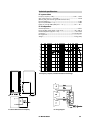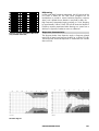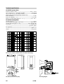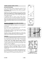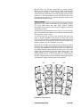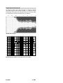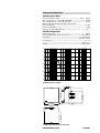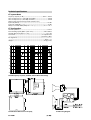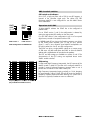
1
E-PAC (Version 3) C, CI and E-Series Systems, MAX/MAX12 User Manual References in the manual WARNING! This refers to a potentially dangerous situation which may lead to personal injury. CAUTION! This refers to a potentially dangerous situation which may lead to damage to the equipment. IMPORTANT! This refers to a situation which may cause the equipment to malfunction. Symbols on the equipment Please refer to the information in the operating manual. WARNING! Dangerous voltage! General Information E-PAC (Version 3 with Display) User Manual Version 6.0E, 05/2002, D2010.E.06 © by d&b audiotechnik AG 2002; all rights reserved. The information presented in this document is, to the best of our knowledge, correct. We will however not be held responsible for the consequences of any errors or omissions. Technical specifications, weights and dimensions should always be confirmed with d&b audiotechnik AG prior to inclusion in any additional documentation. d&b audiotechnik AG Eugen-Adolff-Strasse 134, D-71522 Backnang, Germany Telephone +49-7191-9669-0, Fax +49-7191-95 00 00 E-mail: [email protected], Internet: www.dbaudio.com Contents Safety precautions .....................................................5 Information regarding use of the E-PAC..............................................5 Information regarding use of loudspeakers.........................................6 1. Introduction ...........................................................9 1.1. System concept.............................................................................9 1.2. E-PAC based systems ................................................................10 1.3. Block diagram ............................................................................10 2. E-PAC power amplifier controller ....................... 11 2.1. Digital controller ........................................................................11 2.2. Load Monitoring ........................................................................12 2.2.1. Features............................................................................12 2.2.2. Function ............................................................................12 2.2.3. d&b Load Monitoring/IEC 60849 standard ................13 2.3. Power amplifier ..........................................................................14 2.4. Power supply ..............................................................................14 2.5. Protective circuits .......................................................................14 2.6. Cooling ........................................................................................15 2.7. Remote control & monitoring ...................................................16 2.7.1. Remote-Mode 'RIB/TI212'..............................................16 2.7.2. Remote-Mode 'RIB' .........................................................16 2.7.3. Computer/MIDI control..................................................16 2.7.4. Remote control ................................................................16 2.7.5. Remote status information .............................................17 2.7.6. REMOTE addressing .......................................................17 REMOTE adressing ROPE 2.0 .......................................17 REMOTE adressing ROPE 3 ..........................................18 2.7.7. REMOTE Compatibility ...................................................19 2.8. dbUpdate (Update Manager) ..................................................20 2.9. Controls and indicators .............................................................21 2.9.1. Mains power switch ........................................................21 2.9.2. MUTE/POWER switch (green LED) ...............................21 2.9.3. LEVEL/PUSH MENU (Digital rotary encoder) .............22 2.9.4. Liquid Crystal Display (LCD) ..........................................22 2.9.5. ISP LED- Input Signal Present (green) ...........................22 2.9.6. GR LED - Gain reduction (yellow).................................22 2.9.7. OVL LED - Overload (red).............................................22 2.10. Menu-Mode ................................................................................23 2.10.1. Menu-Tree .....................................................................23 2.10.2. Conventions for the cursor and menu control ..........24 .1 Boot_Screen ...........................................................................25 .2 Main_Menu ............................................................................25 .3 Settings....................................................................................25 Filter_1, Filter_2.....................................................................25 Equalizer.................................................................................26 Parametric Equalizer (PEQ)...........................................26 Notch-Function ...............................................................27 Delay.......................................................................................27 LoImp ......................................................................................27 Speaker Selection..................................................................27 Levels ......................................................................................28 Lock .........................................................................................28 Unlocking the E-PAC......................................................29 Remote....................................................................................29 Options ..................................................................................29 (6.0E) Contents-1 2.11. 2.12. 2.13. 2.14. 2.15. 2.16. Device Name.................................................................. 30 Display Options.............................................................. 30 Information ..................................................................... 31 Log ................................................................. 31 Power Supply.................................................................. 32 Frequency Generator.................................................... 32 Buzzer.............................................................................. 32 Load Monitoring ............................................................ 33 List of possible error messages................................................ 37 2.11.1. Further messages .......................................................... 38 2.11.2. System Reset.................................................................. 38 Connections ................................................................................ 39 2.12.1. Mains power connection and fuse protection .......... 39 2.12.2. INPUT and INPUT LINK................................................ 39 2.12.3. MIX IN ............................................................................ 39 2.12.4. SPEAKER OUT ............................................................... 39 2.12.5. REMOTE......................................................................... 40 2.12.6. SERVICE ......................................................................... 40 Power consumption and power loss........................................ 41 Technical specifications ............................................................. 43 Dimensions .................................................................................. 44 Installation .................................................................................. 45 3. Loudspeaker ...................................................... 47 3.1. Data sheets for the loudspeakers............................................ 47 E0 E1 E3 E9 E12-SUB E18-SUB C6/C690 C4-TOP C4-SUB C7-TOP C7-SUB MAX (LINEAR-Mode) MAX12 (LINEAR-Mode) CI6 CI9 CI8 4. System operation .............................................. 117 4.1. Setting up/stacking the loudspeakers...................................117 4.1.1. Vertical aiming ..............................................................117 4.1.2. Horizontal aiming .........................................................117 4.1.3. Arraying mid/high cabinets ........................................117 4.2. Wiring .......................................................................................118 4.3. Using the E-PAC MIX IN .........................................................119 4.4. Level setting of mid-high and SUB systems..........................120 5. EU declaration of conformity (CE symbol) ......... 121 5.1. EU conformity of loudspeakers .............................................121 5.2. EU conformity of the E-PAC...................................................122 6. Publications list ................................................. 123 Appendix 1: E-PAC Version 3, Setting Sheet ......... 127 Contents-2 E-PAC Version 3, User Manual Safety precautions Before you use our products, read the manual carefully and observe all the safety precautions. They will protect you and help to avoid equipment failures. Keep this manual in a safe place so that it is available for future reference. If you supply d&b products, please draw the attention of your customers to these safety guidelines. Enclose the relevant manuals with the systems. If you require additional manuals for this purpose, you can order them from d&b (order form on the last page). Information regarding use of the E-PAC The device complies with the electromagnetic compatibility requirements of EN 55103 (product family standard for audio, video, audio-visual and entertainment lighting control apparatus for professional use) for the environments E1 (residential), E2 (business and commercial), E3 ( outdoor use in urban areas) and E4 (outdoor use in rural areas). CAUTION! Acoustic interference and malfunctions may occur if the unit is operated in the immediate vicinity of high-frequency transmitters (e.g. wireless microphones, mobile phones, etc.). Damage to the mainframe is unlikely, but cannot be excluded. To meet the EMC requirements, use only shielded cables with properly connected plugs for all signal terminals (INPUT, INPUT LINK, MIX IN). WARNING! The following information is intended to prevent fires and possible electric shocks: The E-PAC is a protective class 1 unit. Make sure that the earth (ground) contact is attached when the unit is in operation. A missing earth (ground) contact may lead to dangerous voltages in the housing and controls. To reduce the possibility of audible hum the mainframe signal ground (XLR pin 1) to earth (ground) connection has a high impedance. It will prevent the unit from static charge but any voltage applied to signal ground will pass through all connectors. To prevent electric shock, make sure that all devices in the signal path are grounded properly. Never connect an amplifier output pin to any other in- or output connector pin or earth (ground). This might damage the mainframe or lead to electric shock. Lay all cables to and from the unit so that they cannot be crushed by vehicles or other equipment and that no-one can step on them. Keep dust, moisture, water or other liquids well away from the unit. Never operate the unit when it is open. (6.0E) Page 5 of 128 Always disconnect the mains power supply when replacing a defective fuse. Only use the type of fuse listed in the specifications. WARNING! Only carry out work specified in this manual and always disconnect the mains power supply. All other work should be performed by trained service staff, especially in the following cases: - Mains power cable or plug has been damaged - Objects or liquids have entered the unit - The unit is not operating normally - The unit was dropped or the housing is damaged Information regarding use of loudspeakers Never stand in the immediate vicinity of loudspeakers driven at a high level. Professional loudspeaker systems are capable of causing a sound pressure level detrimental to human health. Seemingly non-critical sound levels (from approx. 95 dB SPL) can cause hearing damage if people are exposed to it over a long period. In order to prevent accidents when deploying loudspeakers on the ground or when flown, please take note of the following: When setting up the loudspeakers or loudspeaker stands, make sure they are standing on a firm surface. If you place several systems on top of one another, use straps to secure them against movement. Only use accessories which have been tested and approved by d&b for assembly and mobile deployment. Pay attention to the correct application and maximum loading capacity of the accessories as specified in our Rigging Accessories Manual. Ensure that all additional hardware, fixings and fasteners used for installation or mobile deployment are of an appropriate size and load safety factor. Pay attention to the manufacturers instructions and to the relevant safety guidelines. Regularly check the loudspeaker housings and accessories for visible signs of wear and tear, and replace them when necessary. Regularly check all load bearing bolts in the mounting devices. Page 6 of 128 E-PAC Version 3, User Manual WARNING! CAUTION! Only use loudspeakers in the C and E-Series with the P1200A mainframe fitted with the correct controller modules or with a correctly configured E-PAC. The contoller models cone excursion and voice coil temperature of the drivers. When loudspeakers are operated without the correct controller, in addition to losses in tone, there is a risk of damage to the components. Any defects arising from operation other than those specified in this manual will be excluded from any warranty claims. Loudspeakers produce a static magnetic field even if they are not connected or are not in use. Therefore make sure when erecting and transporting loudspeakers that they are nowhere near equipment and objects which may be impaired or damaged by an external magnetic field. Generally speaking, a distance of 0.5 m (1.5 ft) from magnetic data carriers (floppy disks, audio and video tapes, bank cards, etc.) is sufficient; a distance of more than 1 m (3 ft) may be necessary with computer and video monitors. (6.0E) Page 7 of 128 d&b E-PAC Power Amplifier Controller E-PAC ISP LEVEL PUSH MENU GR OVL MUTE POWER SPEAKER OUT E-PAC MIX IN INPUT SERVICE Z2500000101236 C AU TION R ISK O F ELECT RIC SHOCK DO NOT OPEN Made in Germany www.dbaudio.com E-PAC power amplifier controller front and rear views INPUT LINK REMOTE 1. Introduction This user manual describes the facilities and functions of d&b systems which are operated with the E-PAC power amplifier controller. It covers the operation of the E-PAC and the loudspeakers used in these systems. d&b publishes additional application and technical information notes (TI). Examples for different applications and combinations of d&b C-Series and E-Series systems are given in TI 326. A d&b publications list and order form is appended to this manual and we will gladly send you any of the listed publications on request. If you have any comments on the information presented, or feel that something is inadequately explained or not covered, then please tell us using the comments section (Page 49) of the publication order form. 1.1. System concept All d&b loudspeaker systems are designed to meet the following criteria: - Consistent neutral sound over the full working dynamic range - Ease of operation - Simple set up and wiring - Safe and reliable operation - Compact design In order to satisfy these demands d&b developed a complete system concept incorporating the loudspeaker, the loudspeaker specific control electronics (the controller) and the power amplifier. Fundamental to the performance of the loudspeaker is the care taken in the development of individual components resulting in well controlled dispersion, high efficiency and excellent dynamic response. The controller creates the optimum mix of output level capability, operating reliability and longevity, and pure sound quality. Protective circuits continuously model the loudspeaker load through simulation of cone displacement and voice coil temperature ensuring signal level is only reduced when necessary to prevent driver damage. No signal compression takes place within the systems normal operating range and there is no dynamic manipulation of system frequency response enabling most applications and acoustic environments to require no additional signal processing. The power amplifier and control for each loudspeaker are housed within the A1 and P1200A mainframes or the E-PAC power amplifier controller. All systems are compatible, easily combined and complementary, and can be accessed using the d&b remote control system to allow overview and control over the most complex applications. (6.0E) Page 9 of 128 1.2. E-PAC based systems E-PAC is a single channel amplifier with an internal controller for operating C, CI and E-Series, MAX/MAX12 loudspeakers. The controller incorporated in the E-PAC is based on a Digital Signal Processor, DSP, utilising sigma-delta signal conversion. All operational states of the E-PAC as well as the pre-programmed system settings and configurations for d&b C, CI- and E-Series loudspeakers are controlled with a front panel digital rotary encoder in conjunction with the Liquid Crystal Display (LCD). The E-PAC has an additional linear configuration for MAX and MAX12 loudspeakers. The E-PAC is specifically designed for high impedance loads (200 W into 16 ohms, 300 W into 8 ohms), and therefore provides the same output power for a single 16 ohm loudspeaker as one channel of a P1200A mainframe. The nominal 8 ohm impedances of other loudspeakers result in a single cabinet having a maximum SPL of 2 dB less than when driven by a P1200A. If low impedance (LO IMP) mode is selected the E-PAC can drive up to two d&b C, CI or E-Series, or four E0, E1, E3 or CI8 loudspeakers, at reduced output (6 dB). This is useful for situations such as front fill or under balcony use where multiple loudspeakers are needed but maximum output is not required. All the functions of the E-PAC, including programmable internal delay settings, can be remotely interrogated and altered via the RIB, Remote Interface Bridge and a PC. 1.3. Block diagram Output Input 2+/2– Input Amplifier ADC DSP DAC Power Amplifier 1+/1– Link Mix In Display & Controls Remote Error Detection µController Service E-PAC power amplifier controller block diagram Page 10 of 128 E-PAC Version 3, User Manual Impedance Data 2. E-PAC power amplifier controller The E-PAC incorporates a power supply, single channel power amplifier, Digital Signal Processor (DSP), all necessary protection circuits, a remote interface, controls and indicators. The E-PAC is housed in a 2RU high, rugged enclosure and can be operated as a stand alone unit. Optional accessories allow single a E-PAC to be installed in standard 9.5" or 19" equipment racks or flightcases. A dual rack kit is available for mounting a pair side-by-side (see Section 2.16. 'Installation' on page 45). 2.1. Digital controller The controller incorporated in the E-PAC is based on a Digital Signal Processor, DSP, utilising sigma-delta signal conversion. The signal processing includes correction of the frequency response, a high pass filter, limiting and complex protection circuits that model loudspeaker cone displacement and voice coil temperature. CAUTION! System configurations are specific to the characteristics of each loudspeaker and affect the frequency response and maximum output level. To ensure optimum performance and prevent damage to system components each type of loudspeaker has to be used in conjunction with a suitably configured E-PAC. Delay settings up to 220 ms (= 75.68 m/246.1 ft) can be programmed into the controller using the LEVEL/PUSH MENU (digital rotary encoder) in conjunction with the LCD or via the d&b RIB, Remote Interface Bridge, in conjunction with a PC running d&b ROPE control software. IMPORTANT! The E-PAC digital signal processing circuits introduce a processing delay of 1 ms into the signal path, equivalent to a sound path length of 34 cm (1.12 ft). If two identical loudspeakers are driven by digital (E-PAC) and analogue (P1200A) controllers respectively, the 1 ms delay of the E-PAC effectively positions its respective loudspeaker at a distance of 34 cm (1.12 ft) behind the loudspeaker driven by the P1200A. Where the two loudspeakers form an array this will lead to an increase in comb filtering and unpredictable coverage patterns. If the distance between the cabinets is much greater than the path difference of 34 cm (1.12 ft), this effect becomes negligible. Please note that all digital signal processing equipment used in the signal path will delay the signal. For example digital equalizers have a typical processing delay of about 3 ms. DSP ADC Delay Sine-wave generator Loudspeaker System equalization Equalizer function (PEQ/Notch) Limiters: Peak Displacment Thermal DAC Pink-noise generator Block diagram of the DSP software (signal chain) (6.0E) Page 11 of 128 2.2. Load Monitoring 2.2.1. Features d&b Load Monitoring is designed to identify a possible loudspeaker malfunction. This supervision is carried out during regular operation, ensuring that the state of the loudspeaker system is known at all time. d&b Load Monitoring is especially designed to fulfil the requirements stated in the German Standard EN60849 'Elektroakustische Notfallwarnsysteme' (equivalent to international standard IEC 60849 'Sound systems for emergency purposes'). 2.2.2. Function d&b Load Monitoring checks the loudspeaker impedance separately for both the HF and LF channels during regular operation. Given sufficient signal levels LM uses the music or speech Program, however, during pauses, or when the Program Signal level is too low for a good measurement, Pilot Signals can be used (when selected from the menu). The frequencies of the Pilot Signals are 10 Hz and 20 kHz, which are inaudible. These are faded in and out for a duration of approximately 2 seconds (they are not permanently on), and alternate between the high and low frequency without causing any click or interference. During the Calibration process, which must be carried out immediately after the installation of the loudspeaker system, the impedance window limits are determined. Subsequently, the measured impedance during operation is compared against these limits. If a sufficient number of measurements are registered outside the impedance window limits, an impedance error is reported. During the reproduction of the Pilot Signals the impedance is measured within a very narrow band (only at 10 Hz and 20 kHz) and errors can be identified with a higher accuracy than in the broadband Program Signal operation. How often the Pilot Signals are switched on (period duration), how many mis-measurements are accepted and finally the total time until an impedance error is reported, depends on the Detection Time, which can be adjusted in the menu. Page 12 of 128 E-PAC Version 3, User Manual 2.2.3. d&b Load Monitoring and the IEC 60849 (EN 60849) standard Notes The following are only excerpts of the IEC 60849 (EN 60849) standard which affect the d&b Load Monitoring together with the E-PAC power amplifier controller. WARNING! The Detection Time must be set to 100 seconds or lower. Prerequisite is the successful Calibration of Load Monitoring and the correct configuration (see also Chap. 2.10.3. following on page 34). According to 5.) Technical requirements on the system According to 5.2) Automatic operation display When ready for use, every malfunction can be shown either at the E-PAC or remotely on a PC. According to 5.3) Automatic error monitoring g) fault of amplifiers (detected by RIB). J) failure of a loudspeaker circuit (open circuit and short circuit fault). l) failure of a processor for the execution of a software program (control processor detects failure of the DSP, RIB detects failure of the control processor). m) indication of a fault during the memory test: − The E-PAC notifies of a loudspeaker fault or internal fault in three ways, visually by a flashing LED (OVL), as text at the display and acoustically with a buzzer. − Only when all faults are removed (acknowledged), are the visual and acoustic error indications turned off. − Error status is indicated within 100 seconds after the occurrence of a fault. According to 5.4) Supervision of software controlled equipment − The operating system of the E-PAC employs internal watchdog methods of supervision. The control processor recognizes malfunctions of the DSP and through different measures (Mute, restart of the DSP, reload of the DSP program) it will try to remove those malfunctions. If this fails, a fault is reported and the device is muted. − The RIB supervises the control processor. − The E-PAC stores fault status information independently of a mains power failure, these can be recalled remotely or directly on the display. (6.0E) Page 13 of 128 2.3. Power amplifier The single channel power amplifier of the E-PAC maintains high linearity throughout its operational range even into adverse loads. With fast response to, and recovery from overload conditions, stability and accurate performance is guaranteed. A two stage power supply keeps the losses through heat emission low. To maintain sound quality, a limiter circuit prevents the amplifier from continously reaching its maximum output voltage, known as clipping. The E-PAC can deliver 200 W continuous sine wave output power into a 16 ohm load or 300 W into an 8 ohm load. Selecting low impedance mode enables the E-PAC to deliver an output power of 150 W into 4 ohms. These values apply to continuous operation for a minimum of 30 minutes at a maximum ambient temperature of 24°C (75°F). An E-PAC will normally be operated with speech or music programme, complex signals where the average power requirement is below peak power. The E-PAC will continue to operate indefinitely even where the signal has a very low peak to RMS ratio (Crest factor, see section 2.13. on page 41), provided the device is installed to enable the heat generated to be adequately dissipated. 2.4. Power supply The switched mode mains power supply permits worldwide application without the need for mains voltage switching or conversion. Special regulation of the power supply unit additionally guarantees constant output power with fluctuating mains voltage, leading to a substantially higher dynamic stability than a conventional power supply unit of the same performance. This benefits the reproduction of music or speech with a wide dynamic range. Active Power Factor Correction (PFC) is characterised by the current drawn being represented by an almost sinusoidal waveform, resulting in lower loss, in contrast to the pulse shaped current characteristic of power supplies without PFC. This is an advantage where long mains power supply cables are used. The mains voltage and power consumption are recorded by the power supply and can be viewed on the LCD display. 2.5. Protective circuits The E-PAC contains many integrated protective functions: If over temperature occurs, the device switches to mute. After it has cooled down, the output stage resets automatically. The output current limiter (SOA watchdog) prevents damage to the output stage that could occur from a short-circuit or incorrect cabling, while passing the short current peaks drawn by a complex load like a loudspeaker. The mains power connection is protected by a fuse (see Section 2.12.1 on page 39). A mains inrush current limiter provides a 'soft start' and enables several E-PACs to be powered up at the same time without overloading the mains power supply. The maximum current draw during the power up phase is dependant on the mains voltage, however nominal values are 2 A (peak) at 230 V and 4 A (peak) at 115 V. Page 14 of 128 E-PAC Version 3, User Manual The nominal operating range of the E-PAC is between 85 V and 265 V (100 V 15% /230 V +15 %). Where voltages outside of this range are present, a self-resetting protective circuit responds quickly to isolate the internal amplifier power supply leaving only a supervisory circuit to monitor the mains voltage. The display will clearly indicate the fault and voltage value, the display illumination switching off after 10 seconds. The supervision circuit will operate up to 400 V; this allows the E-PAC to survive connection across two phases of a three phase supply. To prevent the E-PAC from cycling on and off with fluctuating mains power supply voltages, the switching thresholds are delayed dependant on the condition breached. These voltage thresholds and corresponding transition delay times are listed in the table on the left. Main voltage V RMS Condition Delay from ⇒ to 276 V ON OFF 1 msec. 267 V OFF ON 2 sec. 83 V OFF ON 2 sec. 77 V ON OFF 20 msec. To ensure a fast response to irregular mains conditions, the mains voltage is registered in the E-PAC as an instantanous peak value, the switching thresholds correlated to that peak value. Peak values are converted to rms values for display purposes. However a real-world AC mains power supply is not typically represented by a perfect sinewave, therefore, the peak-to-rms conversion is based on a typical sinewave with a flat top at 96% of the amplitude of an ideal sinewave. As a consequence, the displayed voltage and the actual switching thresholds will depend on the shape of the mains voltage or the quality of the mains power supply, respectively. 2.6. Cooling The aluminium enclosure acts as a heat sink for the E-PAC power amplifier; it is therefore convection-cooled. To prolong the life of components inside the E-PAC, a small fan located at the front of the E-PAC intakes cooling air through an opening in the rear panel. The quiet running fan is activated at two temperature thresholds. One at 30°C (86°F) and a second, whereby the fan will draw air at a faster flow rate, at above 45°C (113°F). IMPORTANT! When operating and installing the E-PAC, make sure enough air can flow around the enclosure. Never cover or block the intake opening on the rear panel or the exit opening on the front panel. Also refer to Section 2.16. 'Installation' on page 45. WARNING! Do not touch the heat sink. During operation the cooling fins of the heat sink on the enclosure of the E-PAC can reach temperatures of 80°C (176°F). The front and rear panels do not form part of the heat sink and can be touched at any time. (6.0E) Page 15 of 128 2.7. Remote control & monitoring The E-PAC is fitted with a remote interface for various levels of remote control and system supervision. The remote interface connection is opto-coupled and floating. Selection of the remote control setup is made in E-PAC the Remote menu. 2.7.1. Remote-Mode 'RIB/TI212' 'RIB/TI212' is the simplest method of remote control. The mains switch on the rear panel of the E-PAC provides isolation from the input AC supply, in this mode the E-PAC can be switched between ON and STANDBY remotely. By applying an 18 to 28 V DC voltage to the terminals of the remote connector the E-PAC can be switched from 'STANDBYMode' to 'ON'. With the addition of a simple circuit containing an LED, E-PAC error conditions can be remotely displayed. Details of basic circuits for remote power control and fault display are published in d&b Technical Information bulletin TI 212, available on request. A d&b Z6100 RIB (Remote Interface Bridge) can provide switching and status indication for power and error conditions for up to 12 controllers in remote locations. The power switches on the RIB select between the power ON mode and STANDBY. In the event of a voltage blackout at the RIB all connected E-PACs are switched to STANDBY. 2.7.2. Remote-Mode 'RIB' This Remote-Mode RIB allows the remote control and remote monitoring of all functions utilizing a Z6100 RIB (Remote Interface Bridge) and a PC running d&b ROPE software, or a MIDI control device. In this mode the E-PAC continues to operate if there is a voltage blackout at the RIB. A detailed description of remote control with the d&b RIB is given in the RIB user manual (d&b code D2903.E). 2.7.3. Computer/MIDI control Up to eight RIBs can be controlled via RS232, RS422 or MIDI interface. 2.7.4. Remote control with ROPE or MIDI The following E-PAC functions can be remotely controlled: Power On/Off Level control from +6 dB to 57.5 dB in 0.5 dB steps MUTE switching Standby switching Configuration switching (Filter_1, Filter_2, EQ ON, DELAY ON, LO IMP, SPEAKER) − Delay time up to 220 ms in 0.1 ms steps − Load Monitoring − − − − − Page 16 of 128 E-PAC Version 3, User Manual IMPORTANT! IMPORTANT! 2.7.5. Remote status information with ROPE or MIDI The status of the following E-PAC functions can be remotely monitored: − − − − − − − − − Configuration MUTE/POWER switch Level control setting Front panel indicator status (ISP, GR, OVL) Protect status (internal protect, short circuit protect, thermal protect) Temperature status (OK/warning/off) Available headroom (pre-limiter) Gain reduction (due to limiter operation) Loudspeaker impedance faults via Load Monitoring according to EN 60849 (IEC 60849) 2.7.6. REMOTE addressing A detailed description of remote control via the d&b Remote Interface Bridge, RIB, can be found in the RIB user manual (d&b code D2903.E). REMOTE addressing ROPE 2.0 For REMOTE addressing for the E-PAC in ROPE 2.0 applications please refer to the table below. The table describes the RIB Object Addresses for the P1200A mainframe for both the 'Common Objects' and 'Channel A and B Objects'. For the E-PAC the 'Common Objects' and the 'Channel A Objects' are relevant (refer to Chap. 2.7.7. REMOTE Compatibility on page 19). IMPORTANT! A detailed description of REMOTE addressing via the ROPE 2.0 can be found in the ROPE 2.0 user manual (d&b code D2907.E). Address Read/ Write Object 0 0 R W Status Base Device Status Base Device 1 2 3 4 R/W R/W R/W R/W Switch Settings 2 Potentiometer A Switch Settings A Potentiometer B 5 R/W Switch Settings B 6 RD/WR Delay time coarse A 7 RD/WR Delay time fine A 8 R Errors Base Device 9 RD/WR Delay time coarse B 10 R Output Signal + EN60849 10 W Output Signal 11 RD/WR Delay time fine B 12 R/W LED's Controller A 13 R Headroom/GainRed A 0..63:Headroom, 64..127:GainRed, 7-bit coded (0=32dB Hdrm, 64=0dB, 127=31.5dB GR) 14 15 R/W R LED's Controller B Headroom/GainRed B ISP GR OVL ImpErr B Hf ImpErr B Lf 0..63:Headroom, 64..127:GainRed, 7-bit coded (0=32dB Hdrm, 64=0dB, 127=31.5dB GR) Bit 6 6 Binary: 2 Val: 64 Bit 5 5 Binary: 2 Val: 32 Gen-Error Bit 4 4 Binary: 2 Val: 16 SW-Rem Bit 3 3 Binary: 2 Val: 8 LockCmd LockCmd Bit 2 2 Binary: 2 Val: 4 LockMode EQ A+B on Setup_B_4 Setup_B_3 Setup_A_4 Setup_A_3 Attenuation in steps of 0.5dB, 7-bit coded (0=+6dB, 127=–57.5dB) MUTE Setup_Bit2 LO IMP Setup_Bit1 Setup_Bit0 Attenuation in steps of 0.5dB, 7-bit coded (0=+6dB, 127=–57.5dB) MUTE Setup_Bit2 LO IMP Setup_Bit1 Setup_Bit0 Bit 1 1 Binary: 2 Val: 2 PWR Ok Bit 0 0 Binary: 2 Val: 1 PWR On PWR On Delay On B Delay On A Filter 2 Filter 1 Filter 2 Filter 1 Delay in steps of 10 ms, 7-bit coded (max. 22 = 220 ms) Delay in steps of 0.1 ms, 7-bit coded (max. 127 =12.7 ms) Tmp Error Tmp Warn AMP Prot. B AMP Prot. A AMP Error B AMP Error A Delay in steps of 10 ms, 7-bit coded (max. 22 = 220 ms) EN-B-Bit1 EN-B-Bit0 EN-A-Bit1 EN-A-Bit0 Present B Present A ImpErr A Lf ImpErr A Calib A+B**) Delay in steps of 0.1 ms, 7-bit coded (max. 127 =12.7 ms) ISP GR OVL ImpErr A Hf ImpErr B P1200A/E-PAC (V 3.13) object addresses for remote operation with the d&b RIB (6.0E) Page 17 of 128 REMOTE addressing ROPE 3 The communication between the d&b Remote Interface Bridge (RIB) and ROPE 3 is carried out by using driver file (.RDF) which is specific to the loudspeaker. Driver files are available for each mainframe (A1/P1200A) and for the E-PAC (Version 3) in its different versions (Firmware version). The driver file defines both a single 'Control'. Each loudspeaker which can be driven by a mainframe, or an E-PAC has a specific driver file. +6 Function (e.g. 'Level') -14 Control e.g. 'Fader' Driver (.RDF) Driver parameter (Calculations) REMOTE addressing via ROPE 3 driver files (.RDF) The driver file contains all the functions provided by the mainframe or E-PAC to control or monitor the loudspeaker type for which it is written. The ROPE 3 control surface can show devices in two ways (Level 1/ Level 2, see picture below) allowing the operation of functions and monitoring of the operating status. Initialisation via ROPE 3 driver files Starting the 'RUN Mode' in ROPE 3 the connected device will be set as follows: IMPORTANT! − Setting to the selected configuration/set up. Setting the relevant objects only. − Switching into 'Lock Mode' ('LckCmd-Bit'). Example ROPE 3 Driver 'EPACMAX' in Level 1 view Example ROPE 3 Driver 'EPACMAX' in Level 2 view Page 18 of 128 E-PAC Version 3, User Manual RIB-Object 2.7.7. REMOTE Compatibility IMPORTANT! Exchange of d&b amplifiers in RIB/ROPE applications When exchanging d&b's amplifiers or software versions the following has to be considered: The exchaged device needs to be configured correctly: − In the P1200A mainframe the loudspeaker specific controller modules have to be fitted. − In the E-PAC versions 1 and 2 the configuration is defined by setting the DIP switches on the back of the E-PAC. − In the E-PAC version 3 the configuration is indicated by the software version or the related setting menu. IMPORTANT! Object addresse: The number of object addresses which are used by RIB/ROPE depends on the type of controller and loudspeaker. To keep the REMOTE compatibility the following rules apply: a RIB/ROPE applictions are able to drive E-PACs of an older version, for example ROPE 3 with an E-PAC 3.13 driver can communicate with an E-PAC version 1 depending of the existing loudspeaker specific set ups. (In this example E3, E12 and Linear only) Operating functions of ROPE 3 which are not included in the device (e.g. Delay, Load Monitoring) have no effect. b As a result, different ROPE 3 driver files are available for channel A and B. The Object Addresses of channel A corresspond to the Object Addresses of an E-PAC. A RIB/ ROPE application for an E-PAC will therefore always address channel A of the P1200A. c RIB/ROPE applictions are able to drive E-PACs of a new (higher) version. In this situation it has to be considered that devices of a higher verison contain functions which were not previously available. If unused RIB addresses contain data which is not equal to 0 (e.g. by manual programming of the RIB with ROPE 2 or another control), undesired operating conditions can occur. To clear any previously stored setups and reset disconnect the unit from the mains power supply. Resetting is performed by depressing and holding the RESET button while reconnecting the mains power supply. (6.0E) Page 19 of 128 2.8. dbUpdate (Update Manager) Notes: We recommend that the settings of the device are noted before executing an 'update' a 'Setting Sheet is provided for this purpose on page 127 of this manual. IMPORTANT! After executing an 'Update' the setting of the device should be checked and corrected if necessary. The default device name is factory preset with the software version which is originally supplied. If the device name field has not been changed since the original supply this should be manualy edited after update to correctly show the new version number. (refer to sub-menu 'Device Name' on page 30) dbUpdate 'dbUpdate' is a control software for loading new firmware and/or loudspeaker set ups for E-PACs version 3. The software is not supplied with the E-PAC. It can be downloaded from the d&b homepage in the 'Download area' under: www.dbaudio.com Update procedure: A connection (serial - 1:1) between a free COM port of the computer and the SERVICE interface of the E-PAC is required. − The 'Update' procedure takes approx. 10 min. − Connections (Serial connection) should always be made when the device is switched off. − After starting the file 'dbUpdate.exe' the 'Update' procedure is detailed in several steps via dialog screens. 'dbUpdate'-Dialog screen During the 'Update': − the display of the E-PAC is switched off and − the ISP-LED (green) lights up. 1:1-Connection COM-Port SERVICE E-PAC ISP After final 'Update': − the E-PAC is automatically switched on. Page 20 of 128 E-PAC Version 3, User Manual LEVEL PUSH MENU GR OVL MUTE POWER 1:1 RS232 connection between E-PAC and PC 2.9. 2.9.1. Mains power switch [1] The on/off switch is located on the rear panel and isolates the mains power supply to the E-PAC. The MUTE/POWER switch [2] on the front panel has the functions ON/MUTE/STANDBY and does not isolate the E-PAC from the mains power supply. [1] ISP LEVEL PUSH MENU GR OVL MUTE POWER Controls and indicators [2] Controls and indicators IMPORTANT! 2.9.2. MUTE/POWER switch (green LED) [2] When the rear panel mains power switch is set to the on position, the combined MUTE/POWER switch can be used to place the E-PAC either in mute or standby mode. The switch incorporates a green LED indicator which indicates three different states - ON, MUTE and STANDBY. − LED on: ON. The E-PAC is powered on and ready for use. A brief press of the MUTE/POWER switch will mute the E-PAC, a longer press places the E-PAC in standby mode. − LED regular flashing (1:1 duty cycle): MUTE. The E-PAC is muted. In the mute state, the input signal is muted but the power amp is still powered and connected to the speaker output. The E-PAC is unmuted by briefly pressing the MUTE/POWER switch. A longer press of the MUTE/POWER switch will place the EPAC in standby mode. − Regular short flashes (1:8 duty cycle): STANDBY. In standby mode the loudspeaker output is electronically isolated and the E-PAC idles, drawing minimal mains power. Only the most essential functions are provided. Display and network remain functional, the display illumination is switched off after 10 seconds. Pressing the MUTE/POWER switch powers on the E-PAC ready for use. The E-PAC may also be powered back on by remote control from standby mode. When the E-PAC is set to STANDBY (or the mains power is turned off) the movement of the loudspeaker cones in the cabinets connected is no longer damped by the power amplifier output. This removal of the damping makes them susceptible to excitation by other loudspeakers in the surroundings. Audible resonances may occur, and even absorption of low frequency sound energy as the undamped loudspeakers act like a 'bass trap'. To permanently mute single subwoofer cabinets it is therefore preferable to use the MUTE function instead of STANDBY. The STANDBY mode, however, can be of advantage with mid-high systems, because it will remove any residual noise from the system. The MUTE/POWER switch is a 'soft' switch which doesnt electrically isolate the E-PAC from the mains supply. The E-PAC circuitry can be electrically isolated from the mains supply by switching the rear panel mains power switch to its off position. The setting of the MUTE/POWER switch is stored in the E-PAC when the mains power is turned off or disconnected. After reconnecting the E-PAC it will revert to the same status as before disconnection. (6.0E) Page 21 of 128 2.9.3. LEVEL/PUSH MENU (Digital rotary encoder) [3] Operation, configuration and status viewing of the E-PAC are all accessed via the front panel digital rotary encoder; LEVEL/PUSH MENU. In the main menu the encoder acts as a level control. Pushing or turning the encoder gives access to different menu levels or enables configurations or values to be entered. (Refer to section 2.10 following from page 23) 2.9.4. Liquid Crystal Display (LCD) [4] Serves as a user interface and display for all configuration settings and status information. 2.9.5. ISP LED- Input Signal Present (green) [5] − Illuminates when the E-PAC input signal exceeds 30 dBu. The ISP indication is unaffected by the setting of the level control and the MUTE function but will not operate in STANDBY mode. 2.9.6. GR LED - Gain reduction (yellow) [6] − Illuminates depending on the input signal. The E-PAC limiter circuit reduces gain by more than 3 dB. This state is not critical but shows that the system has reached its limits. 2.9.7. OVL LED - Overload (red) [7] The OVL LED indicates either an overload or error condition. − Illuminates depending on the input signal, while the green ISP-LED is lit ⇒ Overload: Either the input signal level is too high or the E-PAC is trying to deliver too high an output current. If in doubt of the reason reduce the input gain at the E-PAC level control. If the error message disappears, the output current has been too high (load impedance too low caused by to many loudspeakers connected to the E-PAC output, or a defective cable or connector). If the condition does not change, the input signal to the E-PAC is too high (greater than +18 dBu). − Flashes (1:1 mark space) : Error! An error message will be displayed. Refer to section 2.11 on page 37. Page 22 of 128 E-PAC Version 3, User Manual [4] [7] ISP GR OVL [6] [5] LEVEL PUSH MENU MUTE POWER [3] Controls and indicators 2.10. Menu-Mode All operational modes of the E-PAC, pre-programmed system settings and configurations for d&b C, CI- and E-series and MAX/ MAX12 (LINEAR mode) loudspeakers can be set directly within the menu tree. Access is via the front panel digital rotary encoder used in conjunction with the LCD display. 2.10.1. Menu-Tree The settings for Filter_1 and Filter_2 are dependent on the loudspeaker configuration (refer to Chap. 2.10.2.3. Settings - Filter_1 and Filter_2 on page 25) (6.0E) Page 23 of 128 2.10.2. Conventions for the cursor and menu control The LCD acts as a user interface for all of the menus within the E-PAC. The cursor is controlled via the digital rotary encoder, LEVEL/PUSH MENU. Cursor conventions and indicators are as following: Position-Cursor Turning the encoder moves the cursor through the menu mode. Turning to the right moves the cursor down in the menu tree or to the right. Turning to the left moves the cursor up in the menu tree or to the left. Pushing the encoder activates the Edit-Cursor, except for switching functions (e.g. 'on/off'). In these instances pushing the encoder leads directly to a change in value or condition (toggle). Edit-Cursor The current set value is displayed beside the cursor and is changed by turning the encoder. Turning to the right leads to a higher value and to the left a lower value. A change is effective immediately except in the functions 'Speaker Selection', 'Lock', 'Remote', 'Device Name' and 'Backlight' where confirmation is required. Exit the edit mode by pushing the encoder and return to the Position-Cursor. Information-Cursor The Information-Cursor is an indicator to the fields within the menu tree where the data displayed cannot be changed. Menu-Change An arrow indicates another menu level. Selecting it with the Position-Cursor and pushing the encoder enters the corresponding sub-menu. Back Exits the selected menu by moving back one level. Scroll-Bar Where a menu tree is longer than can be diplayed, a Scroll-Bar is shown on the right hand side of the display for orientation. Other Cursors or Signs Highlight A highlighted field is an indication that the data displayed can be changed in edit mode (see also Edit-Cursor above). Pointer In the sub-menus 'Lock/code' and 'Device-Name' the highlighted field in edit mode is clearly indicated by an arrow. EQ-Status 'on' In the sub-menu 'Equalizer/Set' the EQ bands with the status 'on', are indicated by a check mark. Page 24 of 128 E-PAC Version 3, User Manual .1 Boot_Screen The boot procedure takes approximately 4 seconds during which the device name, the manufacturers name, d&b audiotechnik AG, and the firmware version is displayed. The transition to the main menu is carried out automatically. Boot_Screen .2 Main_Menu The main menu displays all of the important E-PAC settings in one view: loudspeaker configuration, Load Monitoring (if selected) with or without Pilot Signal, device name, level and delay value. The actual processing delay time is always shown, hence even if the delay is turned 'OFF', the basic delay time of 1 ms is displayed. Main_Menu The lower line shows the 'ON/OFF' status of the following settings: Filter_1, Filter_2, Remote, Lock, LoImp, EQ. If a fault occurs (the red OVL/ Err-LED flashes), an error massage alternating with the device name, is displayed. In Standby-Mode, the display alternates between the device name and Standby. The input sensitivity can be directly adjusted in the main menu with the encoder [3] calibrated in 0.5 dB steps and has a range of 63.5 dB (57.5 dB to +6 dB). This is normally set to 0 dB. In all other cases the encoder is used for operation within the menu tree. .3 Settings From the main menu the 'Settings menu' is entered by pushing the encoder. In the 'Settings menu' the functions 'Filter_1', 'Filter_2', 'Delay' and 'LoImp' can be set and further sub-menus accessed. Setting-Menu, Back, Filter_1 und Filter_2 Loudspeaker Filter_1 Filter_2 E3 CUT HFA E9 CUT HFA LINEAR CUT HFA C6 CUT HFA E12-SUB 140 Hz --- E18-SUB --- --- CI 6 CUT HFA CI 9 CUT HFA E1 CUT HFA C4-TOP --- HFC C4-SUB --- --- C7-TOP CUT HFA C7-SUB 100 Hz --- E0 CUT HFA CI 8 CUT HFA Filter_1, Filter_2 The name of the filter is clearly displayed on the left of the LCD while the 'ON' or 'OFF' status is in the centre and a graphic representation of the filters frequency response on the right. The name and filter frequency response are dependent on the loudspeaker configuration selected (see table on the left). The display [---] indicates, that a filter is not available for the loudspeaker type selected. A detailed description of the filters available for each loudspeaker can be found in the individual data sheets contained in section 3 on page 47. on/off Master filter switch. In addition the transmission function is shown schematically on the right. Loudspeaker and the specific filter functions Filter_1 and Filter_2 (6.0E) Page 25 of 128 Equalizer A 4 band equalizer with an optional Peak-Filter or Notch-Function is incorporated into the signal path before the limiting circuit (refer to chap. 2.1 on page 11). The EQ function has a Master on/off while each of the four bands can be switched independently. If several EQ bands are set with a high boost in the same frequency range, it can cause overflows within the DSP. These errors are recognized internally and the E-PAC will enter mute mode. The error message 'DSP Error 16' is displayed. By changing the centre frequency of single filters or by switching off the EQFunction the error can be cleared. Settings menu, Equalizer IMPORTANT! on/off Master switch for the EQ function. Set The 'Set' sub-menu gives access to the four EQ-Functions EQ_1, EQ_2, EQ_3 and EQ_4. A check mark ( ) beside any of the four EQ-bands indicates that the corresponding EQ is turned on. The graphical representation below shows the complete transfer function of all (active) filters. Equalizer, Set menu EQ [number] Pushing the encoder enters the edit mode of the corresponding EQ band. PEQ/Notch Pushing the encoder enables selection of either the 'PEQ' (Peak filter) or 'Notch' function. [Number] Pushing the encoder allows access to the individual EQ filters directly, without the necessity to revert to the Set-Menu. on/off Pushing the encoder switches the corresponding EQ on or off. Parametric Equalizer (PEQ) The following parameters can be edited in 'PEQ' mode: F Filter centre frequency adjustable from 20 Hz to 20 kHz in 3% steps. Q The Q of the filter is adjustable from 0.5 ... 25 in 10% steps. In addition, the bandwidth (BW) as a result of the Q is displayed as a value (2.0 ... 0.04 octaves) in a non-editable field. G Gain, adjustable from 18dB to +6dB in 0.2dB steps. Page 26 of 128 E-PAC Version 3, User Manual Set menu, EQ-Function Notch-Function The following parameters can be edited in the 'Notch' mode: Set menu, Notch-Function F Filter centre frequency adjustable from 20 Hz to 20 kHz in 3% steps. Q The Q of the filter is adjustable from 0.5 ... 25 in 10% steps. In addition, the bandwidth (BW) as a result of the Q is displayed as a value (2.0 ... 0.04 octaves) in a non-editable field. G The parameter 'Gain' (G) cannot be edited in 'Notch' mode. The centre frequency is fully attenuated (⇒ ∞ dB). Delay Settings menu, Delay, LoImp and Speaker on/off Master delay switch. [Delay-Value] Delay time adjustable between 1 to 220 ms in steps of 0.1 ms, or a corresponding value depending on the parameter selected. [Parameter] Enables selection of the delay display value in either milliseconds [ms]; metres [m]; or feet [ft]. LoImp on/off Master LoImp switch. In low impedance mode the E-PAC is configured to drive low impedance loads. Gain and the maximum output voltage is reduced by half (6 dB) enabling the E-PAC to drive loads at a nominal 4-8 ohms at lower power. For example in LoImp four 16 ohms loudspeakers can be operated. The noise floor of the amplifier is also reduced by approximately 5 dB. Speaker Selection Speaker Selection menu Speaker Enables selection of individual loudspeaker configurations in the following order: E3, E9, LINEAR (MAX/MAX12), C6 (C690), E12SUB, E18-SUB, CI6, CI9, E1, C4-TOP, C4-SUB, C7-TOP, C7-SUB, E0, CI8. OK If the loudspeaker configuration is edited then the confirmation request 'OK' will flash. Selecting 'OK' and pressing the encoder will confirm the configuration and exit the sub-menu 'Speaker Selection'. Cancel ( ⇒ Back ) Exits the sub-menu 'Speaker Selection'. The previous configuration will remain active. (6.0E) Page 27 of 128 Levels The following are displayed both as bar graphs and as numeric values. Exit the 'Levels-Menu' by pushing the encoder. Gain Input gain, the numeric value is displayed in dB. Adjustable over the range 57.5 dB to +6 dB in 0.5 dB steps (see also 2.10.2.2 Main Menu on page 25). Input Input signal level, the numeric value is displayed in dBu. The small vertical line [A] represents the threshold of input level above which the OVL LED (red) registers an overmodulation of the input. The colon [B] provides a peak hold function. Gain [A] [B] Headr. Levels monitor (bar graphs) Power The actual output power, displayed as a numeric value in watts, the colon [B] provides a peak hold function. Impedance Z The impedance of the loudspeaker(s) presented to the output of the E-PAC, displayed only as a numeric value in ohms. The value shown is dependant on the level and frequency range of the the input signal. It is a reliable indication of the output power level from 1 mW, and covers the range 0 ohms (short circuit) to 255 ohms (open output, I = 0, Z ⇒ ∞). Lock 1. Entering the sub-menu 'Lock', will position the cursor at the menupoint 'Code'. 2. Pushing the encoder enters edit mode. The pointer ( ), indicates the entry position for new, or edited, characters. An alphabet, in capital letters only, is displayed in the bottom line. 3. By turning the encoder, each alphabet character can be highlighted. Turning left moves the cursor to the beginning of the alphabet (⇒ A), turning right to the end of the alphabet (⇒ Z). 4. By pushing the encoder, the highlighted letter is entered in the upper line and the pointer advances one place. 5. Repeat steps 1 to 4 until the complete password is entered. 6. Exit edit mode by moving the cursor to the return sign ( ) and pushing the encoder. If an existing password is changed to a length shorter than the previous entry, the remaining letters are deleted automatically. Single characters can be kept by pushing the encoder as each character is highlighted, the pointer advancing one place after each entry. The editing position can be scrolled through the password characters by pushing and turning the encoder simultaneously. Page 28 of 128 E-PAC Version 3, User Manual : Power Headroom Shows the relationship between modulation and gain reduction (GR). The small vertical line [A] indicates the gain reduction threshold, which is 0 dB headroom/0 dB gain reduction, the colon [B] provides a peak hold function. The GR LED (yellow) indicates a gain reduction of more than 3 dB. Code Enables the input of a new, or editing of an existing password (Maximum 7 characters): : Input Lock menu Edit mode Mode There are two options to protect the E-PAC against unintentional operation: 1. Press 2s - Prevents accidental operation by locking the front panel controls. 2. Code - Password protection that prevents operation by unauthorized persons. Lock now Pushing the encoder switches the E-PAC into Lock mode and exits the sub-menu 'Lock'. Back Exits the sub-menu 'Lock' without entering Lock mode. Unlocking the E-PAC An attempt to change the status of an E-PAC in Lock mode will be met by the message 'Unlock: Press knob 2s' being briefly displayed. Unlock the E-PAC as follows; 1. Press 2s - push and hold the encoder for a minimum of 2 seconds until 'Lock' disappears from the lower line of the LCD. 2. Code - push and hold the encoder for a minimum of 2 seconds untill 'Please enter password' is displayed. The password is entered as described under 'Code' above. An incorrectly entered password will revert the E-PAC to the main menu in Lock mode. A 'Code protected' E-PAC with a forgotton password can released through a System-Reset (See Section 2.11.2. System Reset on page 38). Remote Remote menu Mode Enables selection of the following modes for remote control (see section 2.7. remote control/remote monitoring, on page 16): off: RIB/TI212: RIB: RIB/RS232: dbCAN: No remote control. Remote control in accordance with TI212. Remote control via d&b RIB/ROPE. Refer to chap. 2.7.3. on page 16. Reserved for a future upgrade. Contrary to the other convention the remote mode is only activated (by pushing the encoder) after leaving the edit mode. Options The 'Options' menu allows further settings and status retreival in addition to the operational configurations and parameters of the E-PAC. Options menu (6.0E) Page 29 of 128 Device Name Device Name Enables the assignment or editing of a device name (Maximum 15 characters): 1. Entering the sub-menu 'Device Name', will position the cursor at the beginning of the existing entry. As a factory preset 'E-PAC' followed by the firmware version is entered. 2. Pushing the encoder enters edit mode. The pointer, ( ), indicates the entry position for new, or edited, characters. An alphabet, in capital letters only, is displayed in the bottom line. 3. By turning the encoder, each alphabet character can be highlighted. Turning left moves the cursor to the beginning of the alphabet ( ⇒ A), turning right to the end of the alphabet (⇒ Z). 4. By pushing the encoder, the highlighted letter is entered in the upper line and the pointer advances one place. 5. Repeat steps 1 to 4 until the complete device name is entered. 6. Exit edit mode by moving the cursor to the return sign ( ) and pushing the encoder. If an existing device name is changed to a length shorter than the previous entry, the remaining letters are deleted automatically. Device Name menu Edit mode Single characters can be kept by pushing the encoder as each character is highlighted, the pointer advancing one place after each entry. The editing position can be scrolled through the password characters by pushing and turning the encoder simultaneously. OK Selecting 'OK' and pressing the encoder will confirm the new setting and exit the sub-menu 'Device name'. Cancel ( ⇒ Back ) Exits the sub-menu leaving the previous device name installed. Display Options Contrast Enables adjustment of the display contrast. Backlight Enables the following settings: off: Display illumination permanently off. on: Display illumination permanently on. timeout 10s: Display is illuminated when the encoder or the MUTE/POWER-switch is pressed and switches off 10 seconds after the last operation. (Note: In Standby mode the display illumination reverts to 'timeout 10s') Page 30 of 128 E-PAC Version 3, User Manual Display menu Information Temp. The temperature of the E-PAC heatsink. Information monitor Firmware The version of software installed in the E-PAC. DSP-Ver The version of active software installed in the E-PAC DSP. Ser-No. (S/N) Serial number of the E-PAC. Logbook monitor Log A log book containing information relating to the use and enviromental conditions experienced throughout the operating life of the E-PAC. The bar graphs are proportional to the time the E-PAC has been connected to a mains power supply and switched on. For example a half filled standby bar graph would indicate that the E-PAC has been in standby mode for half its operating life. On time Hours counter. Indicating the amount of time the E-PAC has been connected to a mains power supply and switched on. Standby Proportion of the 'On Time' the E-PAC has been in Standby mode. ISP Proportion of the 'On Time' an input signal was present at the E-PAC. GainRed Proportion of the 'On Time' the E-PAC has been operated with gain reduction. Overload Proportion of the 'On Time' the E-PAC has been operated with too high input level or output current. Amp Prot A numerical value indicating the number of times the E-PAC has entered the error condition 'Amp Protect', possibly due to a current overload caused by a low impedance or short circuit connected to the output. Amp Err A numerical value indicating the number of times the E-PAC has entered the error condition 'Amp Error' due to an internal fault. Temp off A numerical value indicating the number of times the E-PAC has switched off with the error condition 'Overtemperature' due to overheating. ImpErrLF A numerical value indicating the number of impedance faults in the LF section of the connected loudspeaker (Load Monitoring). (6.0E) Page 31 of 128 ImpErrHF A numerical value indicating the number of impedance faults in the HF section of the connected loudspeaker (Load Monitoring). Proportionate temperature ranges These display the proportion of 'On Time' the E-PAC has been operated within the temperature ranges listed. Power Supply The firmware version of the switched mode power supplys micro controller is listed on the right hand side of the top line. Mains The value of the mains voltage power supply to which the E-PAC is connected in volts. The typical accuracy is 2 %, however the value is dependent on the quality of the mains voltage. (see section 2.5. protection circuits/mains voltage supervision, on page 15, paragraph 4). Power Supply monitor Power Power consumption in watts. The typical accuracy is 5 %. Frequency Generator The frequency generator is a sweepable sine wave or pink noise generator. The generator serves as a simple test of the functionality of loudspeakers or for finding room resonances. The generator is in the signal path after the delay and before the loudspeaker equalization (refer to chap. 2.1 on page 11). The test tone will sum with any input signal present. NOTE: The frequency generator is used to provide the Pilot Signals for the load monitoring function. When using 'Load Monitoring' with Pilot Signals the frequency generator function is not available. Frequency Generator menu IMPORTANT! Mode Generator function is switched off. off: Selects the sine-wave generator. Sin: Pink: Selects the pink noise generator. Level Level of the frequency generator in dBu, covering a 63.5 dB range from 57.5 dB to +6 dB in 0.5 dB steps. The level value corresponds to the output level of typical signal generators needed to produce an equal output level from the E-PAC. Frequency Frequency adjustable over the range 10 Hz to 20 kHz in 1 Hz steps. Buzzer Acoustical signal for error messages in conjunction with the 'OVL' display [7] ('Error-LED' - see section 2.9.7, on page 22). on/off Master switch for turning the buzzer on or off. Page 32 of 128 E-PAC Version 3, User Manual Buzzer Function Load Monitoring Load Monitoring IMPORTANT! Notes: The Load Monitoring is designed for the supervision of up to two loudspeakers connected in parallel (see also 'Notes on non-automated settings' on page 36). The Load Monitoring does not function when: − the device is muted. − the Pilot Signals function is turned off. − the signal levels are too low. Load Monitoring menu Mode on/off Switching the Load Monitoring On or Off. Load Monitoring menu IMPORTANT! Pilot Signals on/off Switching the Pilot Signals On or Off (see also 'Frequency Generator' on page 32). Note: To get reliable measurements, Pilot Signals should always be used. These are activated only when required, i.e. when the device detects that measurements using the regular program (music/speech) are not providing meaningful results. Detection Time The maximum time the system needs to recognize loudspeaker malfunctions. WARNING! In accordance with the EN 60849 (IEC 60849) standard the Detection Time must be set to 100 seconds, or lower. Under unfavourable circumstances it may take substantially longer before an error is recognized (see also 'Notes on non-automated settings' on page 36). Driver menu For this example the LF Driver menu is described, the same menu is also available for the HF Driver. All settings (except 'Last-Err Z') are determined during the initial adjustment. In order that the reliability of the fault detection is not affected, these automatically determined values should only be changed after a thorough investigation has taken place, these can then be manually adjusted. Driver menu Definition of values: Z-Min Program Lower window limit of the impedance, when measured with Program (music/speech). Z-Max Program Upper window limit of the impedance, when measured with Program (music/speech). Z-Min Pilot Lower window limit of the impedance, when measured with Pilot Signal. (6.0E) Page 33 of 128 Z-Max Pilot Upper window limit of the impedance, when measured with Pilot Signal. Pilot-Level Output voltage of the Pilot Signal. U-Threshold Switching threshold from measurement with Pilot Signals to measurement with Program. Last-Err Z Last determined impedance value that has led to a reported impedance error. This value will remain unchanged even after acknowledgment of the error message. If following the error acknowledgment a renewed error is reported, then the previous stored value will be overwritten. IMPORTANT! The Calibrate menu Safety precautions: − − − − Nobody should ever stand directly in front of the loudspeakers! Calibration should never be carried out during a live event. Calibration should only be carried out with the E-PAC in MUTE. When the Calibration Mode in the Load Monitoring menu is set to 'Off', the Load Monitoring is switched off. WARNING! The Calibration menu for Load Monitoring. Before Calibration starts, a warning dialog is displayed. Calibration uses inaudible Pilot Signals and audible pink noise. Calibration can also be run remotely. Calibrate menu Cancel ( ⇒ Back ) Exits the sub-menu 'Calibrate'. Calibrate By choosing 'Calibrate' the adjustment process is initiated. Calibrate procedure During Calibration the following message is displayed: Cancel By pushing the Encoder (LEVEL/PUSH MENU) the Calibration process can be terminated prior to completion. Calibrate procedure Finished The Calibration process lasts approximately 30 seconds and is indicated on the display (see below) when completed. Ok By pushing the Encoder (LEVEL/PUSH MENU) the cursor will return to the opening screen of the 'Calibration' menu. Selecting 'Cancel' at this point completes the Calibration and exits the sub-menu 'Calibrate Load Monitoring'. Page 34 of 128 E-PAC Version 3, User Manual Calibrate procedure What happens during the Calibration? − Load Monitoring is switched off. − The impedance limits are determined for measurements made with Pilot Signals and Program during operation. − The minimum signal levels for the Pilot Signals are determined; these are necessary to ensure exact measurement results. − The display values for the last impedance error ('Last-Err Z') are set to 0.0 Ohms. Possible error messages during the Calibration Cancelled by User! The user has interrupted the Calibration either by pushing the Encoder or remotely. Current too low The level was increased to the maximum value, but the minimum current wasn't reached. In most cases this error message will be displayed when a loudspeaker is not connected or there is a faulty cable. Current too high The maximum current was exceeded at minimum level. In most cases this error message will be displayed when a short circuit in the cable or connector has occurred. Power is off The E- PAC is in Standby mode and an adjustment is not possible. IMPORTANT! Remote via RIB Load Monitoring adjustment via RIB For safety reasons the Calibration is locked. To enable Calibration the following procedure should be followed: − Switch on Load Monitoring (set 'Enable Bit') − Switch off Load Monitoring (reset 'Enable Bit') − Calibrate (set 'Calib-Bit') WARNING! IMPORTANT! Notes: − It is strongly recommended to protect the Calbration function in ROPE by means of the Confirm dialog! − If the Calibration was successful, reset the 'Calib-Bit' in the E-PAC. − If the Calibration was not successful, reset the 'Calib-Bit' in the E-PAC again and set one or more ImpErr-Bits for 2 seconds. − If the user resets the 'Calib-Bit' during Calibration then the process is cancelled. Reset of impedance errors To reset error indications either: − Power Off/On at the device or remotely. − Switching the Load Monitoring Off/On at the device or remotely. − Setting the 'ImpErr-Bits' remotely. (6.0E) Page 35 of 128 Notes on non-automated settings d&b Load Monitoring checks the impedance of the attached load periodically and reports any transgression of the upper or lower limits. The three situations described below are exceptions where the automatic Calibration settings will not suffice for the operating conditions, and where a manual adjustment to the impedance parameters is required. Manual adjustment should only be undertaken after consultation with d&b Application Support to ensure that the reliability of fault detection is not compromised in any way. a If a malfunction creates only a minor impedance change that lies within the limit values of the loudspeaker, the malfunction is not displayed, this can happen when operating with Pilot Signals set to 'Off'. If only a single component of the loudspeaker is malfunctioning (e.g. a loudspeaker chassis or a component of the crossover network), a median impedance measurement could result when using a music Program Signal, which can lie within the normal operating values. Using the extended limits for operation without Pilot Signal ('Z-Min Program' and 'Z-Max Program') can amplify this effect. b If two loudspeakers are connected in parallel, the complete failure of one driver only influences the impedance proportionately; the resulting impedance would be roughly double. Identification of such a defect depends on the setting of the Calibrated or adjusted limiting values. c If the loudspeaker impedance changes to the extent that it exceeds a limiting value, a malfunction will be displayed even though there isnt one. This could be caused by a very high voice coil temperature (continuous operation at high output), or driving the loudspeaker with narrowband signals when operating without the Pilot Signals. Page 36 of 128 E-PAC Version 3, User Manual WARNING! 2.11. List of possible error messages − System Error [nnn]: An internal fault has occured. The − − − − − − − − − − − − − number nnn can provide your d&b service partner with information on the exact cause of the fault. Switch the E-PAC off and on again. Program Error [nnn]: A fault has occured in the control processor. The number nnn can provide your d&b service partner with information on the exact cause of the fault. Switch the E-PAC off and on again. Overvoltage ([xxx] V): Mains overvoltage. The E-PAC will switch into standby mode. Undervoltage ([xxx] V): Mains undervoltage. The E-PAC will switch into standby mode. Power Supply Error [nnn]: A fault has occured in the switched mode power supply. The number nnn can provide your d&b service partner with information on the exact cause of the fault. Invalid DSP Program: The operating software for the DSP is not present or is faulty. The E-PAC will switch to mute. Switch the E-PAC off and on again. If the fault continues consult your d&b service partner. Invalid Speaker Data: The DSP data of the loudspeaker configuration selected is not present or faulty. The E-PAC will switch to mute. DSP Error [nnn]: A fault has occured in the digital signal processor (DSP), the E-PAC will switch to mute. The number nnn can provide your d&b service partner with information on the exact cause of the fault. Switch the E-PAC off and on again. Amp. Error: An internal fault has occurred in the amplifier, the E-PAC will switch to mute and the loudspeaker output switched off. The E-PAC does not contain any user servicable components, the device must be returned to a d&b service partner. Amp. Protect: Output current too high, possibly caused by a short circuit or fault in a loudspeaker cable or another low impedance condition. The E-PAC will be muted and the loudspeaker output switched off. Once the cause of the fault has been identified and removed, the E-PAC has to be switched to standby mode to clear the error status. Temp. Warning ([xx] °C): The temperature of the E-PAC is very high, the load should be reduced. Overtemperature ([xx] °C): The temperature of the E-PAC is too high and will be muted, the loudspeaker output switched off. After cooling down to a permitted operating temperature the E-PAC will switch on automatically. Remote Error [nnn]: A fault has occurred in the remote control connection. This error message can appear if no network is connected, or if no other devices are available on the network. SpkrFault ([xx Ω/xx Ω]): Both LF and HF paths of the connected loudspaeaker have failed. The display shows the value (ohms) which led to the fault. (6.0E) Page 37 of 128 − SpkrFault LF ([xx Ω]): The LF path of the connected loudspaeaker has failed. The display shows the value (ohms) which led to the fault. − SpkrFault HF ([xx Ω ]): The HF path of the connected loudspaeaker has failed. The display shows the value (ohms) which led to the fault. 2.11.1. Further messages The following messages are for information on the status of the E-PAC and not error messages: − Standby: Indicates the E-PAC is in standby mode (see section 2.7.2. MUTE/POWER switch, on page 17). − Unlock: Press knob 2s: Indicates that the E-PAC has been locked to protect against accidental or unauthorised operation. Push and hold the encoder for a minimum of two seconds to unlock (see 'Lock' menu on page 28). 'Code', indicates the E-PAC has been password protected. 2.11.2. System Reset Following a system reset operation any configurations previously stored in the E-PAC will be lost. The E-PAC can be reset to the factory settings as follows: 1. Isolate the E-PAC from the mains power supply by switching off the power switch on the rear panel. 2. Push and hold down the MUTE/POWER switch, switch on the power supply to the E-PAC again and release the MUTE/ POWER switch. Page 38 of 128 E-PAC Version 3, User Manual IMPORTANT! 2.12. Connections [9] 2.12.1. Mains power connection [8] and fuse protection [9] A 3-pin IEC socket with an integrated fuse holder is provided for connecting the E-PAC to the mains power supply. A suitable power cable is supplied. [8] WARNING! Before you connect the device, check that the mains voltage and frequency corresponds to the specifications on the configuration sticker on the rear of the E-PAC. Only connect the E-PAC to mains power supplies with an earth (ground) conductor. Make absolutely sure that earth (ground) is connected correctly. A replaceable 20 mm fuse is integrated in the IEC mains socket 5 A Time Lag (T)). This is connected in series to the power supply and fails if the current drain is exceeded. There is a spare fuse in the fuse holder. If the fuse has failed disconnect the E-PAC from the mains supply before replacement. Only use a fuse of the correct type and nominal current value. Before restoring power to the E-PAC all cabling should be checked for faults. If in any doubt disconnect all signal and loudspeaker connections. [13] [12] [11] [10] 2.12.2. INPUT [11] and INPUT LINK [10] The E-PAC signal input connector is a 3 pin female XLR. Below and wired in parallel is a 3 pin male XLR input link connector used to feed the input signal on to the next device in the system signal chain. 2.12.3. MIX IN [12] Pin 2 (pos. signal) Pin 1 (GND) Pin 3 (neg. signal) Pin assignments on E-PAC signal inputs A 3 pin female XLR connector provides a MIX IN input. A second signal fed to this input is summed to the main INPUT. If Left and Right components of a stereo source are fed to the main INPUT and MIX IN connections then a mono sum signal is derived from the speaker output. Please note that the resultant output is 3 dB higher. The output on the INPUT LINK connector is derived from the signal fed to the INPUT connector. An additional signal fed to the MIX IN connector will not appear at the INPUT LINK output. 2.12.4. SPEAKER OUT [13] NL4 Speaker out The E-PAC is fitted with a single Speakon-NL4 speaker output connector. With configuration settings which transmit full-range signal (e.g. E3 or LINEAR) all four pins on the Speakon connector are driven, pins 1+ and 2+ carry positive signal, 1 and 2 carry negative signal. With SUB configurations selected pin 1+ is disconnected automatically. This prevents mid-high cabinets from accidental damage by subwoofer signal. (6.0E) Page 39 of 128 2.12.5. REMOTE [14] The E-PAC is fitted with a two-wire serial remote control interface, (2 x RJ 45). All pins of both connectors are wired in parallel allowing either to be used as the input. Where remote control networking conforms to a 'Bus or Ring topology' one connector is used for the incoming signal and the second connector allows for direct connection to another device. The remote interface connections are opto-coupled. Remote operation is detailed in section 2.7. 'Remote control and monitoring' on page 16. A detailed description of remote control via the d&b Remote Interface Bridge, RIB, can be found in the RIB user manual (d&b code D2903.E). 2.12.6. SERVICE [15] The SUB-D9 SERVICE interface (RS 232) allows the loading of operating software updates and the specific loudspeaker set ups (see also Chap. 2.8 'dbUpdate (Update Manager)' on page 20). [15] [14] 1......8 1......8 Pin 1 Pin 2 Pin 3 Pin 4 Pin 5 Pin 6 Pin 7 Pin 8 n.c. n.c. n.c. CAN hi CAN lo n.c. RIB data RIB gnd Pin assignment for remote control SERVICE connector (SUB-D9) Page 40 of 128 E-PAC Version 3, User Manual Signal waveform 2.13. Power consumption and power loss Crest factor Sine wave 1.4 Pink noise, compressed music 2.8 Compressed music 3.5 Music with medium dynamic range 5 Speech, music with wide dynamic range 8 The power required from the mains supply and the waste heat produced by the amplifiers power loss are variable figures depending on the load impedance and the signal levels and characteristics (e.g. speech, music). In practice, the theoretical peak power consumption of a system will only be sustained for a short period of time. Basing mains current and air conditioning plant requirements on the peak power consumption of the sound system would result in a generously over-specified installation. The key factor in power consumption calculations is the crest factor of the signal - the ratio of peak to sustainable RMS voltage of the signal. Examples of Crest factors Power input and electrical (⇒ thermal) power loss for different signal and load conditions can be derived from the graphs shown below. 500 156 loss output 400 power [W] 300 300 102 123 125 200 196 118 86 85 159 120 79 47 100 80 78 60 50 34 -0 Crestfactor 1.4 2.8 3.5 1.4 16 ohms 2.8 3.5 1.4 8 ohms 2.8 3.5 4 ohms (LO IMP) Maximum output power and power loss of E-PAC for different signal characteristics (Crest factors) at full level. 400 power [W] power [W] 400 consumption consumption 100 100 loss loss 30 5 10 100 200 average output power [W] Power consumption and loss of E-PAC as a factor of output power (WRMS into 8 ohms) with pink noise signal (6.0E) 30 5 10 100 200 average output power [W] Average power consumption and loss of E-PAC as a factor of output power (WRMS into 16 ohms) with pink noise signal Page 41 of 128 Page 42 of 128 E-PAC Version 3, User Manual 2.14. Technical specifications Displays ISP .............................................................................Input Signal Present indicator (green) GR ...................................................................................Gain Reduction indicator (yellow) OVL.....................................................................................Overload/Error indicator (red) MUTE/POWER ..................................................... On/Mute/Standby indicator (green) Liquid Crystal Display (LCD) ........................................................................ 120 x 32 Pixel Controls I/O............................................................................................................ Main power switch MUTE/POWER .........................................................................On/Mute/Standby switch LEVEL/PUSH MENU....................................................................... Digital rotary encoder Access to all functions including: Level control .......................................................57.5 dB ... +6 dB with 0.5 dB detents Configurations.............................................................................................. CUT/HFA/HFC 4 band equalizer..............................................................................Optional Peak/Notch Delay setting......................................................1.0 ... 220 msec. with 0.1 msec. detents System set up.....................C, CI and E-Series loudspeakers/linear (MAX/MAX12) Impedance measurement (Z)..................................................................... 0 to 255 ohms Protection...................................................Operator input inhibit/password protection Remote control............................................................................................... RIB(TI212)/RIB Device name.................................................................................... 15 alphanumeric digits Display illumination ...........................................................................Off/On/Timeout 10s Frequency generator .... alternative sine wave, 10 Hz ... 20 kHz with 1 Hz detents ....................................................................................................................................Pink Noise ...............................................................................57.5 dB ... +6 dB with 0.5 dB detents Buzzer...................................................................... Acoustical signal for Error Messages Load Monitoring...................................................Impedance Monitoring according to .............................. EN 60849/IEC 60849 'Sound Systems for emergency purposes' ................................... alternative Program and/or Pilot Signal at 10 Hz and 20 kHz Connectors INPUT ..................................................................................... 3 pin XLR (female), balanced INPUT LINK .................................................................3 pin XLR (male) parallel to INPUT MIX IN .................................................................................. 3 pin XLR (female) balanced SPEAKER OUT.................................................................................................................... NL4 Pin assignments full range speakers.........................................................1+/1, 2+/2 Pin assignments active subwoofers....................................................................... 2+ / 2 REMOTE ......................................................................................................................2 x RJ45 SERVICE ..............................................................................................................SUB-D9 (PS2) Protection circuits Mains inrush current limiter ......................................2 A peak at 230 V, 4 A at 115 V Overvoltage protection.................................................................................... up to 400 V Self resetting overtemperature protection ................................................ 75°C /167°F Output short and open circuit protection...............................................................±20 A Speaker switch on delay ............................................................................... approx 2 sec. Data (linear-setting with subsonic filter) Rated output power (THD + N < 0.1%)...............................1 x 200 W into 16 ohms ........................................................................................................... 1 x 300 W into 8 ohms LO IMP mode................................................................................. 1 x 150 W into 4 ohms Frequency response (1 dB)..................................................................... 35 Hz 22 kHz THD+N (20 20k Hz) ...........................................................................................< 0.05 % IM (SMPTE) .................................................................................................................. < 0.1 % Slew rate.............................................................................................................. 50 V / µsec. Damping factor (20 1k Hz into 16 ohms) ........................................................... > 160 S/N ratio (unweighted, RMS, 0 dB).....................................................................> 94 dBr S/N ratio with MUTE (unweighted).................................................................. > 104 dBr Input impedance......................................................................................................22 kohms Input-CMR (20 1k Hz)........................................................................................... > 50 dB Maximum input level ............................................................................................... +21 dBu (sum of INPUT and MIX IN) (6.0E) Page 43 of 128 Digital Signal Processing Sampling rate................................................................................................ 48 kHz / 24 bit Basic delay.................................................................................................................... 1 msec. Maximum delay setting .................................................... 220 msec. (75.68 m/246.1 ft) Power consumption (typical values) Standby ..............................................................................................................................2 W ON, without signal ........................................................................................................ 27 W ON, Standard signal* at 16 Ohms........................................................................... 79 W On, Standard signal* at 8 Ohms ............................................................................114 W * Standard signal: Pink noise, 1/8 nominal power Dimensions, weight and power supply Height x width x depth ...........................................................2 RU x 190 mm x 331mm ......................................................................................................................2 RU x 7.5" x 13" Weight........................................................................................................... 4.7 kg / 10.4 lb Universal voltage range switched mode power supply with active power factor correction (PFC) Mains voltage rating................................................................ 85 265 V / 50 60 Hz Mains fuse.......................................................................................................5A Time lag (T) 2.15. Dimensions 336 [13.23"] 190 [7.48"] ISP LEVEL PUSH MENU 88 [3.46"] E-PAC GR OVL MUTE POWER ISP LEVEL PUSH MENU GR OVL 76 [3.00"] E-PAC 357 [14.06"] 338 [13.31"] 88 [3.46"] 240 [9.45"] 222 [8.74"] MUTE POWER E-PAC ISP LEVEL PUSH MENU E-PAC GR OVL MUTE POWER ISP LEVEL PUSH MENU GR OVL MUTE POWER E-PAC enclosure dimensions with rack mount kits in mm [inch] Page 44 of 128 E-PAC Version 3, User Manual 76 [3.00"] 483 [19.00"] 465 [18.30"] 2.16. Installation A single E-PAC may be installed in a 9.5" equipment rack or a standard 19 equipment rack or flightcase. A single E-PAC or a pair side-by-side may be installed in a standard 19" equipment rack or flightcase. E-PACs require two rack units and, including connectors, a minimum rack depth of 40 cm (15.7"), mounting ear to rack rear panel. 2 cm / 0.8" Vent IMPORTANT! E-PAC ISP GR OVL LEVEL MUTE PUSH MENU POWER E-PAC ISP GR OVL It is recommended that additional support be provided within the rack by using the rear mounted rack ears [3]. This is particularly important if E-PACs are being racked for road use. LEVEL MUTE PUSH MENU POWER E-PAC ISP LEVEL MUTE PUSH MENU POWER The E-PAC enclosure can get hot during operation, therefore allow a gap of at least 2 cm (3/4") between an E-PAC and the rack top/bottom panels, or other equipment above or below (see figure on the left). This is not necessary between adjacent E-PACs. E-PAC GR OVL ISP LEVEL PUSH MENU GR OVL MUTE POWER 2 cm / 0.8" Vent E-PAC, Rack mounting When installing E-PACs always allow sufficient free air flow around the enclosure and never block or cover the rear panel air intake vent or the front panel air outlet vent. If E-PACs are to be installed in sealed equipment racks, then additional fan modules will be needed. The E-PAC air intake is on the rear panel; therefore external fans should supply air to the rear side of the rack. E-PACs with solo/dual rack mount kits (6.0E) Page 45 of 128 The solo rack mount kit (Z2501) allows one E-PAC to be mounted either to the left or the right hand side in a standard 19" equipment rack or flightcase. The solo rack mount kit (Z2501) includes the following parts: − − − − − [3] 1 front blanking panel [5] 1 front rack mounting bracket [2] 1 rear mounted rack ear [3] 4 mounting rails [1] 6 Allen screws [S], Allen key [4] [1] [2] [5] The dual rack mount kit (Z2502) allows two EPACs side-by-side to be mounted in a standard 19" rack or flightcase. The dual rack mount kit (Z2502) includes the following parts: − − − − − 2 front rack mounting brackets [2] 2 rear mounted rack ears [3] 2 connector brackets [4] 8 mounting rails [1] 16 Allen screws [S], Allen key Rack mount kit parts The solo rack mount kit (Z2503) allows one E-PAC to be mounted in a 9.5 equipment rack or flightcase. The solo rack mount kit (Z2503) includes the following parts: − − − − 2 front rack mounting brackets [2] 2 rear mounted rack ears [3] 4 mounting rails [1] 8 Allen screws [S], Allen key The mounting rails [1] are inserted into channels located in the side walls of the E-PAC aluminum enclosure. The different fittings [2,3,4 and 5] are attached using countersunk Allen (Hex) screws [S]. [S] [1] [2] Attachment of brackets and rack ears Page 46 of 128 E-PAC Version 3, User Manual 3. Loudspeaker On the following pages you will find data sheets for the d&b loudspeakers which can be operated with the E-PAC. The data sheets contain information about the loudspeakers and operation with their respective E-PAC and P1200 controller settings. 3.1. Data sheets for the loudspeakers The following data sheets are a compilation of the individual data sheets for the d&b loudspeakers. Please note that the version number for the individual data sheets, shown as a footnote on the respective pages, can differ from the version number of this manual. E0 E1 E3 E9 E12-SUB E18-SUB C6/C690 C4-TOP C4-SUB C7-TOP C7-SUB MAX (LINEAR-Mode) MAX12 (LINEAR-Mode) CI6 CI9 CI8 (6.0E) Page 47 of 128 Page 48 of 128 E-PAC Version 3, User Manual E0 The E0 is a compact, coaxial 2-way loudspeaker fitted with a 5 LF driver and 1 dome tweeter and has a maximum sound pressure level of 116 dB SPL. With a frequency response that covers the 80 Hz to 20 kHz band and a 100° conical dispersion, the E0 will display an identical response whether deployed horizontally or vertically, making it extremely versatile for use in near field applications such as delay and surround sound systems where a discreet yet distortion free reproduction of speech and music is required. For applications requiring bass extension the E0 can be combined with the d&b E12 subwoofer. The E0 is housed in a cleverly shaped strong polyamide cabinet containing magnetic shielding of the LF driver, and has a rigid metal grill that protects the front of the loudspeaker. Recessed into the rear is a quad push connector and self-locking ball joint with integrated mounting arm that incorporates an M10 female thread. Along with a selection of d&b rigging accessories the E0 can be deployed quickly and easily in a variety of configurations. Whilst the loudspeaker components are shielded against magnetic radiation, we advise a minimum distance of 15 cm between the E0 and susceptible equipment (e.g. PC and video monitors). CAUTION! The E0 loudspeaker can only be operated with a d&b E-PAC power amplifier controller (display version only) configured for the E0 otherwise there is a risk of damaging the loudspeaker. Connections The E0 has two pairs of push connectors wired in parallel facilitating quick connection to additional loudspeakers and the E-PAC. We recommend a loudspeaker cable with minimum Cross Sectional Area (CSA) of 0.5 mm. The minimum CSA required for a single cabinet can be calculated from: cross-section [mm ] = single length of cable [m] /50 Where multiple E0 loudspeakers are connected in parallel the minimum CSA required is obtained by multiplying the above result by the number of cabinets. Operation with E-PAC E0 with TV spigot Selecting E0 mode in the E-PAC enables two E0 loudspeakers to be driven at full power. LO IMP mode configures the E-PAC to drive a maximum of four E0 loudspeakers with a 6 dB reduction in input level to the speakers. For acoustic adjustment the functions CUT and HFA can be selected. E0 with wall mount adapter E0 Data Sheet E0 CUT circuit Set to CUT, a high pass filter with a 120 Hz cut off frequency is inserted in the controller signal path. The E0 is now configured for use with d&b C and E-Series active subwoofers. HFA circuit The HFA (High Frequency Attenuation) mode rolls off the HF of the E0 to provide a balanced frequency response when a unit is placed close to listeners in near field or delay situations. HFA begins gradually at 1 kHz, dropping by approximately 3 dB at 10 kHz. This roll off mimics the decline in frequency response experienced when listening to a system from a distance in a typically reverberant room or auditorium. 10 5 0 -5 -10 -15 -20 -25 Dispersion characteristics -30 20 Due to the coaxial driver design, the horizontal and vertical dispersion characteristics of the E0 are identical. The diagram below shows dispersion angle versus frequency plotted using lines of equal sound pressure (isobars) at 6 dB and 12 dB. Isobar diagram E0 E0 (1.0E) 100 1k 10k 20k Frequency response correction of HFA circuit Technical specifications E0 system data Frequency response (5 dB).....................................................................80 Hz ... 20 kHz Max. sound pressure with E-PAC (1 m, free field) ......................................116 dB SPL (SPLmax peak, pink noise test signal with crest factor of 4) Input level (SPLmax) ....................................................................................................+9 dBu Input level (100 dB-SPL / 1 m)..................................................................................4 dBu Polarity to controller INPUT (XLR pin 2: + / 3: ) ...................................LF: + / HF: E0 loudspeaker Nominal impedance .................................................................................................16 ohms Power handling capacity (RMS / peak 10 ms)............................................50 /400 W Nominal dispersion angle ................................................................................100° conical Weight ............................................................................................................... 2.5 kg (5.5 lb) 10 5 0 -5 -10 -15 -20 -25 -30 20 100 1k 10k 20k E0 frequency response, standard and CUT setting 45 [1.77"] 28 [1.1"] 144 [5.67"] 233 [9.17"] 0˚ -9 1722 [6.77"] 0˚ 1700 [6.69"] ±30˚ E0 dimensions in mm [inch] E0 Data Sheet E0 E1 The E1 cabinet is a full range, two way bass-reflex enclosure. Fitted with two 5" LF drivers passively connected to a ring radiator with a 60° conical dispersion. The E1 cabinet is constructed from marine plywood with an impact resistant paint finish. The front of the loudspeaker cabinet is fitted with a rigid metal grill covered with a replaceable acoustically transparent foam. A connector plate with two parallel wired Speakon connectors, together with M8 threaded inserts for mounting brackets on each panel allow the E1 to be mounted in almost any position. The outstanding feature of the E1 is its neutral sound balance coupled with an extraordinarily high output capability for a cabinet of such a size. The E1 frequency response covers a 75 Hz to 15 kHz band making it extremely versatile and ideal for use in near field, delay, effects and ultra compact monitor. Used with an auxiliary subwoofer system, the E1 can also easily reproduce high level music programs. Suitable subwoofers are E12-SUB, E18-SUB or C7-SUB. CAUTION! 1+ 1 2+ 2 1+ 1 2+ 2 Connector wiring Only operate E1 loudspeakers with a d&b P1200A mainframe fitted with E1 controller modules or a d&b E-PAC version 3 in E1 configuration, otherwise there is a risk of damaging the loudspeaker components. Connections Passive Crossover The E1 cabinet is fitted with a pair of Speakon-NL4 connectors. All four pins of both connectors are wired in parallel. The E1 uses the pin assignments 1+/1. Pins 2+/2 are designated to active d&b subwoofers. Using one connector as the input, the second connector allows for direct connection to additional loudspeakers. The connector plate is fitted to the E1 rear panel. Operation with P1200A Up to four E1 loudspeakers can be driven by each P1200A power amplifier channel. Fitting one E1-CO and one subwoofer controller module allows a single mainframe to drive four E1 and two active subwoofer cabinets (E18-SUB or C7-SUB). All cabinets can be linked together locally and fed by a single four-wire cable from either mainframe output connector. E1 Data Sheet E1 E1 controller module switches E1-CO CUT CUT switch and indicator Set to CUT, a high pass filter with a 110 Hz cut-off frequency is inserted in the controller signal path. The yellow CUT LED illuminates. The E1 system is now configured for use with d&b C or E-Series active subwoofers. OVL Operation with E-PAC (only possible with E-PAC version 3 with display) ISP GR MUTE To drive E1 cabinets the E-PAC has to be configured to E1 mode. For an E-PAC version 3, the configuration is set via a front panel digital rotary encoder in conjunction with an LCD. The CUT and HFA settings are available. The characteristics of the CUT setting is explained on the previous page under the section "E1 controller module switches". 0 -6 The E-PAC can drive up to two E1 cabinet at an output power of 300 watts. LO IMP mode allows the E-PAC to drive four E1 cabinets with a 6 dB reduction of input level to the speakers. HFA setting In HFA mode (High Frequency Attenuation), the HF response of the E1 system is rolled off. The yellow HFA LED illuminates. The HFA circuit configures the E1 loudspeakers to provide a natural, balanced frequency response when a unit is placed close to listeners in near field or delay use. High Frequency Attenuation begins gradually at 1 kHz, dropping by approximately 3 dB at 10 kHz. This roll off mimics the decline in frequency response experienced when listening to a system from a distance in a typically reverberant room or auditorium. +6 -12 dB Controls on E1 controller module 10 5 0 -5 -10 -15 -20 -25 -30 20 100 1k 10k 20k Frequency response correction of HFA circuit E1 (1.0E) Technical specifications E1 system data Frequency response (5 dB).....................................................................75 Hz ... 15 kHz Max. sound pressure (1 m, free field) ................................................................... 118 dB (SPLmax peak, pink noise test signal with crest factor of 4) Input level (SPLmax) ....................................................................................................+7 dBu Input level (100 dB-SPL / 1 m)..................................................................................8 dBu Polarity to controller INPUT (XLR pin 2: + / 3: ) ...................................LF: + / HF: E1 loudspeaker Nominal impedance .................................................................................................16 ohms Power handling capacity (RMS / peak 10 ms)........................................ 100 / 400 W Nominal dispersion angle (hor. x vert.) .......................................................... 60° conical Connections ...............................................................................................2 x Speakon-NL4 Pin assignments .......................................................................................................... 1+ / 1 Weight ..............................................................................................................10.4 kg (23 lb) 10 5 0 -5 -10 -15 -20 -25 -30 20 100 1k 10k 20k E1 frequency response, standard and CUT switch settings E1 wiring diagram E1 cabinet dimensions in mm [inch] E1 Data Sheet E1 E3 60 The E3 cabinet is a full range, two way bass-reflex enclosure. Fitted with a single 6.5" LF driver passively connected to a 1" HF compression driver coupled to a constant directivity horn with a 90° x 60° dispersion. Illustrated in the drawing on the left is an E3 with the standard 90° horizontal horn configuration. The horn can be rotated through 90° for a reversed 60° x 90° (h x v) dispersion. 90 The E3 cabinet is constructed from marine plywood with an impact resistant paint finish. The front of the loudspeaker cabinet is fitted with a rigid metal grill covered with a replaceable acoustically transparent foam. A connector plate with two parallel wired Speakon connectors, which can be swapped between the rear and side of the cabinet, together with pairs of M8 threaded inserts for mounting brackets on each panel allow the E3 to be mounted in almost any position. The outstanding feature of the E3 is its neutral sound balance coupled with an extraordinarily high output capability for a cabinet of such a size. The E3 frequency response covers a 80 Hz to 17 kHz band making it extremely versatile and ideal for use in near field, delay, effects, ultra compact monitor and miniature array systems. Used with an auxiliary subwoofer system, the E3 can also easily reproduce high level music programs. Suitable subwoofers are E12-SUB, E18-SUB or C7-SUB. With an asymmetrical cabinet design and an extensive range of mounting and rigging accessories (please refer to the E-Series brochure) E3 cabinets can be mounted or flown almost anywhere and used in pairs to create 120° or 180° horizontal arrays. CAUTION! Only operate E3 loudspeakers with a d&b P1200A mainframe fitted with E3 controller modules or a d&b E-PAC in E3 configuration, otherwise there is a risk of damaging the loudspeaker components. Altering the HF horn dispersion The E3 HF horn has a square flange allowing it to rotate through 90°. Two dispersion angles, 90° and 60°, are engraved on the flange, the value on the horizontal edge indicates the loudspeakers horizontal dispersion angle. To change the horn dispersion, first remove the front grill by undoing the Allen screws (M4x25 mm) at the top and bottom of the grill using a 2.5 mm Allen key. Using a 3 mm Allen key, undo the 4 Allen screws (M4x25 mm) which hold the horn in place. The horn can then be rotated through 90°, refastened and the front grill replaced. E3 array, 120° coverage E3 Data Sheet E3 Connections 1+ 1 2+ 2 The E3 cabinet is fitted with a pair of Speakon-NL4 connectors. All four pins of both connectors are wired in parallel. The E3 uses the pin assignments 1+/1. Pins 2+/2 are designated to active d&b subwoofers. Using one connector as the input, the second connector allows for direct connection to additional loudspeakers. The connector plate is fitted to the E3 rear panel. Next to it, on the left hand side panel, is a metal blank plate with the cabinet details and serial number. The connector and blank plates can be swapped over to allow mounting brackets to be fitted to the back panel of the cabinet or to allow it to be placed on its back as a stage monitor. The plates are removed by undoing the four 2.5 mm hex head screws securing each panel. The connector wiring is disconnected in order to swap the panels. Make sure when reconnecting the wiring that the red wire goes to pin 1+ and the black wire to pin 1 on the Speakon connector board. Passive Crossover 1+ 1 2+ 2 Connector wiring IMPORTANT! Operation with P1200A Up to four E3 loudspeakers can be driven by each P1200A power amplifier channel. Fitting one E3-CO and one subwoofer controller module allows a single mainframe to drive four E3 and two active subwoofer cabinets (E18-SUB or C7-SUB). All cabinets can be linked together locally and fed by a single four-wire cable from either mainframe output connector. -! CUT HFA OVL E3 controller module switches ISP CUT switch and indicator Set to CUT, a high pass filter with a 110 Hz cut-off frequency is inserted in the controller signal path. The yellow CUT LED illuminates. The E3 system is now configured for use with d&b C or E-Series active subwoofers. HFA switch and indicator In HFA mode (High Frequency Attenuation), the HF response of the E3 system is rolled off. The yellow HFA LED illuminates. The HFA circuit configures the E3 loudspeakers to provide a natural, balanced frequency response when a unit is placed close to listeners in near field or delay use. High Frequency Attenuation begins gradually at 1 kHz, dropping by approximately 3 dB at 10 kHz. This roll off mimics the decline in frequency response experienced when listening to a system from a distance in a typically reverberant room or auditorium. GR MUTE 0 -6 +6 -12 dB Controls on E3 controller module 10 5 0 -5 -10 -15 -20 -25 -30 20 100 1k 10k 20k Frequency response correction of HFA circuit E3 (2.0E) REMOTE LO IMP 1234 DELAY ON REMOTE LO IMP ON ON 1 2 3 4 5 6 Operation with E-PAC To drive E3 cabinets the E-PAC has to be configured to E3 mode. 1 2 3 4 5 6 7 8 SPKR HFA CUT E-PAC version 1 E-PAC version 2 E-PAC Configuration for E3 For an E-PAC version 1 and 2, the configuration is selected by setting the appropriate DIP switches on the rear panel. For an E-PAC version 3, the configuration is set via a front panel digital rotary encoder in conjunction with an LCD. The CUT and HFA settings are available on versions 2 and 3. The characteristics of the CUT and HFA settings are explained on the previous page under the section "E3 controller module switches". The E-PAC can drive up to two E3 cabinet at an output power of 300 watts. LO IMP mode allows the E-PAC to drive four E3 cabinets with a 6 dB reduction of input level to the speakers. Dispersion characteristics The diagrams below show dispersion angle vs frequency plotted using lines of equal sound pressure (isobars) at -6 dB and -12 dB. E3 isobar diagram, configuration 90° horizontal (standard) E3 isobar diagram, configuration 90° vertical E3 Data Sheet E3 Technical specifications E3 system data Frequency response (5 dB) .................................................................... 80 Hz ... 18 kHz Max. sound pressure (1 m, free field) ...................................................................122 dB (SPLmax peak, pink noise test signal with crest factor of 4) Input level (SPLmax).................................................................................................... +9 dBu Input level (100 dB-SPL / 1 m) .............................................................................. 10 dBu Polarity to controller INPUT (XLR pin 2: + / 3: ) ................................... LF: + / HF: E3 loudspeaker Nominal impedance................................................................................................. 16 ohms Power handling capacity (RMS / peak 10 ms) ........................................120 / 480 W Nominal dispersion angle (hor. x vert.)............................................................. 90° x 60° ................................................................................................ (rotatable through 60° x 90°) Connections............................................................................................... 2 x Speakon-NL4 Pin assignments...........................................................................................................1+ / 1 Weight................................................................................................................ 7.2 kg (16 lb) 10 5 0 -5 -10 -15 -20 -25 -30 20 100 1k 10k 20k E3 frequency response, standard, CUT and HFA switch settings E3 wiring diagram E3 cabinet dimensions in mm [inch] E3 (2.0E) E9 The E9 cabinet is a full range, two way bass-reflex enclosure fitted with a single 12" LF driver passively connected to a 2" HF compression driver coupled to a vertically asymmetrical 90° x 50° CD horn. The asymmetry of the HF horn means that the E9 has a vertical coverage pattern with a downward tilt. The actual vertical dispersion is 20° above and 30° below the cabinet axis. The E9 cabinet is constructed from marine plywood and has an impact resistant paint finish. The front of the loudspeaker cabinet is fitted with a rigid metal grill covered with a replaceable acoustically transparent foam. The cabinet top plate has an integral handle and four M10 threaded inserts for mounting brackets and rigging. The L shaped metal plate at the bottom of the cabinet also incorporates a handle, four M10 threaded inserts, a socket to accept a loudspeaker stand and, on the rear panel, two parallel wired Speakon-NL4 or EP-5 connectors. The E9 frequency response is truly full range covering a 50 Hz to 17 kHz band - even without an additional subwoofer, this is quite sufficient for many applications. The wide horizontal and asymmetric vertical dispersion makes the E9 especially suitable for close coverage applications up to 15 m (50 ft) where it can be deployed to best advantage mounted on a high stand. The E9 can also be used as a stage monitor by simply placing the cabinet rear side down on stage (baffle angle 45°). 1+ 1 2+ 2 Within a larger system E9s are ideal as delays and for close, wide coverage work. The precisely angled rear side panels of the cabinet allow E9 cabinets to be simply placed side by side forming an array with accurate 90° horizontal coverage per loudspeaker. To simplify array construction an extensive range of mounting and rigging accessories are available - please refer to the E-Series brochure. Passive Crossover 1+ 1 2+ 2 Connector wiring CAUTION! The E9 system can be used with the d&b active subwoofer systems E12-SUB, E18-SUB or C7-SUB. When operated with the P1200A mainframe the E9 may also be combined with the E15-BX passive bass extension. Only operate E9 loudspeakers with a d&b P1200A mainframe fitted with E9 controller modules or a d&b E-PAC (version 2) in E9 configuration, otherwise there is a risk of damaging the loudspeaker components. Connections EP-5 1 2 3 4 5 NL4 1+ 1 2+ 2 n.c. The E9 cabinet is fitted with a pair of Speakon-NL4 connectors. All four pins of both connectors are wired in parallel. The E9 uses the pin assignments 1+/1. Pins 2+/2 are designated to C and ESeries active subwoofers. Using one connector as the input, the second connector allows for direct connection to additional loudspeakers. The E9 can be supplied with EP-5 output connectors as an option. Pin equivalents of Speakon-NL4 and EP-5 connectors are listed in the table on the left. Speakon- NL4 and EP-5 pin assignments E9 Data Sheet E9 Operation with P1200A Up to two E9 loudspeakers can be driven by each P1200A power amplifier channel. Fitting one E9-CO and one subwoofer controller module allows a single mainframe to drive two E9 and two active subwoofer cabinets (E18-SUB or C7-SUB). All cabinets can be linked together locally and fed by a single four-wire cable from either mainframe output connector. The E9 can also be used with the E15-BX bass extension cabinet. The E15-BX cabinet is equipped with a passive crossover network and simply connects in parallel with the E9 cabinet without the need for any additional control electronics. One E9 and one E15BX cabinet can be driven by each P1200A output channel. E9 controller module switches E9 Standard setting If the CUT switch and BX switch are not selected the module is configured for use with E9 loudspeakers when used as a stand alone system without subwoofers. CUT switch and indicator Set to CUT, a high pass filter with a 110 Hz cut-off frequency is inserted in the controller signal path. The yellow CUT LED illuminates. The E9 system is now configured for use with d&b C or E-Series active subwoofers. BX switch and indicator When the E9 is used with the passive E15-BX subwoofer, i.e. E9 and E15-BX are linked to the same amplifier output, the BX switch should be selected. The LF level - boosted by the bass extension cabinet - is then attenuated by 3 dB, thereby increasing headroom at bass frequencies. When E9 loudspeakers are deployed as stage monitors selecting the BX switch reduces the low frequency energy gained from the coupling effect of floor placement. SUB (CUT and BX both selected) Selecting the CUT and BX switches activates a lowpass filter. The module now transmits frequencies from 50 to 110 Hz only, allowing the d&b E15-BX to be driven as an active subwoofer. CUT SUB BX OVL ISP GR MUTE 0 -6 +6 -12 dB Controls on E9 controller module The E9-CO drives Speakon pins 1+/1 (EP-5: 1/2). Therefore the SUB setting is not suitable to drive d&b C/E-Series active subwoofer cabinets. IMPORTANT! Operation with E-PAC DELAY ON REMOTE LO IMP To drive E9 cabinets the E-PAC has to be configured to E9 mode. For an E-PAC version 2, the configuration is selected by setting the appropriate DIP switches on the rear panel. For an E-PAC version 3, the configuration is set via a front panel digital rotary encoder in conjunction with an LCD. The CUT and HFA settings are available on versions 2 and 3. The characteristics of the CUT setting are explained on the previous page under the section "E9 controller module switches". The functions BX and SUB are not available with the E-PAC controller. E9 (2.0E) ON 1 2 3 4 5 6 7 8 SPKR HFA CUT E-PAC Configuration for E9 (E-PAC version 2) The E-PAC can drive a single E9 cabinet at an output power of 300 watts. LO IMP mode allows the E-PAC to drive two E9 cabinets with a 6 dB reduction of input level to the speakers. HFA setting In HFA mode (High Frequency Attenuation), the HF response of the E9 system is rolled off. The HFA circuit configures the E9 loudspeakers to provide a natural, balanced frequency response when a unit is placed close to listeners in near field or delay use. 10 5 0 -5 -10 High Frequency Attenuation begins gradually at 1 kHz, dropping by approximately 3 dB at 10 kHz. This roll-off mimics the decline in frequency response experienced when listening to a system from a distance in a typically reverberant room or auditorium. -15 -20 -25 -30 20 100 1k 10k 20k Frequency response correction of HFA circuit (only available with E-PAC) Dispersion characteristics The diagrams below show dispersion angle vs frequency plotted using lines of equal sound pressure (isobars) at -6 dB and -12 dB. The nominal 90° horizontal dispersion is maintained from 20 kHz down to 900 Hz. E9 isobar diagram E9 Data Sheet E9 Technical specifications E9 system data Frequency response (5 dB) .................................................................... 50 Hz ... 17 kHz Max. sound pressure (1 m, free field) with P1200A ...........................................128 dB Max. sound pressure (1 m, free field) with E-PAC ..............................................126 dB (SPLmax peak, pink noise test signal with crest factor of 4) Input level (SPLmax)..................................................................................................+12 dBu Input level (100 dB-SPL / 1 m) .............................................................................. 13 dBu Polarity to controller INPUT (XLR pin 2: + / 3: ) ................................... LF: + / HF: E9 loudspeaker Nominal impedance....................................................................................................8 ohms Power handling capacity (RMS / peak 10 ms) ........................................200 / 800 W Nominal dispersion angle ................................. horizontal 90°, vertical +20° / 30° Connections............................................................................................... 2 x Speakon-NL4 .....................................................................................................................(optional 2 x EP-5) Pin assignments...........................................................................................................1+ / 1 ................................................................................................................................ (EP-5: 1 / 2) Weight................................................................................................................. 26 kg (57 lb) 10 5 0 -5 -10 -15 -20 -25 -30 20 100 1k 10k 20k E9 frequency response, standard, BX and CUT switch settings E9 wiring diagram E9 cabinet dimensions in mm [inch] E9 (2.0E) E12-SUB The E12-SUB is a compact bass-reflex design employing a high excursion 12" driver. The large, specially shaped reflex port enables the E12-SUB to achieve high sound pressure levels with minimal power compression and breathing effects. The E12-SUB cabinet is constructed from marine plywood and has an impact resistant paint finish. The front of the loudspeaker cabinet is fitted with a rigid metal grill covered with a acoustically transparent foam. The cabinet incorporates a steel handle in one side and two parallel wired Speakon-NL4 connectors on the rear panel. CAUTION! Fitted to the top panel is an M20 threaded flange to accept the Z5013 Loudspeaker stand for the deployment of a single E3 cabinet. To ensure sufficient stability the maximum permissible weight of 10 kg (22 lbs) for the cabinet mounted on top of the stand must not be exceeded. Designed to be actively driven using the E-PAC Power Amplifier Controller the E12-SUB covers the 50 Hz to 120 Hz frequency band. The compact E12-SUB has an extraordinarily high output capability for a cabinet of such a size - enough to support up to two E3 cabinets. It is ideal for permanent or mobile use in small and medium venues. CAUTION! Connections 1+ 1 2+ 2 The E12-SUB cabinet is fitted with a pair of Speakon-NL4 connectors. All four pins of both connectors are wired in parallel. The E12-SUB uses the pin assignments 2+/2. Pins 1+/1 are designated to C and E-Series full range cabinets. Using one connector as the input, the second connector allows for direct connection to additional loudspeakers. 1+ 1 2+ 2 Operation with E-PAC Connector wiring To drive E12-SUB cabinets the E-PAC has to be configured to E12-SUB mode. For an E-PAC version 1 and 2, the configuration is selected by setting the appropriate DIP switches on the rear panel. REMOTE LO IMP 1234 DELAY ON REMOTE LO IMP ON ON 1 2 3 4 5 6 The configuration E12-SUB on E-PAC version 2 is identical to configuration SUB on E-PAC version 1. For an E-PAC version 3, the configuration is set via a front panel digital rotary encoder in conjunction with an LCD. 1 2 3 4 5 6 7 8 SPKR HFA CUT E-PAC version 1 Only operate the E12-SUB with a d&b E-PAC in E12-SUB configuration (SUB configuration with E-PAC version 1), otherwise there is a risk of damaging the loudspeaker components. E-PAC version 2 A 140 Hz function is available on version 3 (Firmware version 3.13) of the E-PAC. The E-PAC can drive a single E12-SUB cabinet at an output power of 300 watts. We do not recommend that two E12-SUB cabinets are driven in LO IMP mode as the 6 dB reduction in input level to the loudspeakers results in no gain in acoustical output. E-PAC Configuration for E12-SUB E12-SUB Data Sheet E12-SUB 140 Hz Function (Filter_1) With E-PAC version 3 (Firmware version 3.13) only. If the 140 Hz function (Filter_1) is selected, the upper operating frequency of the system is increased from 120 Hz to 140 Hz. This setting allows the E12-SUB to operate with up to four E0 loudspeakers. Technical specifications E12-SUB system data Frequency response (5 dB) ....................................................................50 Hz ... 120 Hz Max. sound pressure (1 m, free field).....................................................................125 dB (SPLmax peak, pink noise test signal with crest factor of 4) Input level (SPLmax)..................................................................................................+14 dBu Input level (100 dB-SPL / 1 m) .................................................................................8 dBu Polarity to controller INPUT (XLR pin 2: + / 3: ) ...................................................LF: + E12-SUB loudspeaker Nominal impedance....................................................................................................8 ohms Power handling capacity (RMS / peak 10 ms) ........................................200 / 800 W Connections ............................................................................................... 2 x Speakon-NL4 Pin assignments...........................................................................................................2+ / 2 Weight................................................................................................................. 20 kg (44 lb) 10 5 0 -5 -10 -15 -20 -25 -30 20 100 1k 10k 20k E12-SUB frequency response E12-SUB cabinet dimensions in mm [inch] E12-SUB (3.0E) E18-SUB The E18-SUB is a compact, very low tuned bass-reflex design employing a single 18" driver. The E18-SUB loudspeaker cabinet is constructed from marine plywood and has an impact resistant paint finish. The front of the loudspeaker cabinet is fitted with a rigid metal grill covered with a replaceable acoustically transparent foam. Also at the front, fittings at the top and bottom edges of the cabinet are used to secure an optional transport lid E7908. The cabinet incorporates a pair of steel handles and, on the rear panel, four heavy duty wheels and two parallel wired Speakon-NL4 or EP-5 connectors. Fitted to the top panel is an M20 threaded flange to accept the Z5013 Loudspeaker stand for the deployment of a full range cabinet. Designed to be actively driven using the d&b P1200A mainframe or the d&b E-PAC, the E18-SUB is normally used to support d&b full range cabinets such as the E9, C6 or E3 by covering the 38 Hz to 110 Hz frequency band. CAUTION! Only operate E18-SUB loudspeakers with a d&b P1200A mainframe fitted with E18 controller modules or a d&b E-PAC (version 2) in E18-SUB configuration, otherwise there is a risk of damaging the loudspeaker components. Connections The E18-SUB cabinet is fitted with a pair of Speakon-NL4 connectors. All four pins of both connectors are wired in parallel. The E18-SUB uses the pin assignments 2+/2. Pins 1+/1 are designated to C and E-Series full range systems. Using one connector as the input, the second connector allows for direct connection to additional loudspeakers. The E18-SUB can be supplied with EP-5 output connectors as an option. Pin equivalents of Speakon-NL4 and EP-5 connectors are listed in the table below. 1+ 1 2+ 2 1+ 1 2+ 2 Connector wiring EP-5 1 2 3 4 5 NL4 1+ 1 2+ 2 n.c. Speakon- NL4 and EP-5 pin assignments E18-SUB Data Sheet E18-SUB -& Operation with P1200A Up to two E18-SUBs can be driven by each P1200A power amplifier channel. Fitting one E18-SUB-CO and one C or E-Series TOP controller module allows a single mainframe to drive two E18SUB and two (E3: four) mid/high cabinets. All cabinets can be linked together locally and fed by a single four-wire cable from either mainframe output connector. 160Hz OVL E18 Controller module switches ISP 160Hz switch and indicator If the 160Hz switch is selected (yellow 160Hz LED illuminated), the upper operating frequency of the system is raised from 110 Hz to 160 Hz. This setting can be used when E18-SUBs are used with the C6 system - the 160Hz setting on the C6-CO should also be selected to increase the C6 system's headroom (see C6 data sheet). MUTE Operation with E-PAC -6 0 To drive E18-SUB cabinets the E-PAC has to be configured to E18-SUB mode. For an E-PAC version 2, the configuration is selected by setting the appropriate DIP switches on the rear panel. DIP switches 1 and 2 (CUT and HFA) are not functional with the configuration E18-SUB. For an E-PAC version 3, the configuration is set via a front panel digital rotary encoder in conjunction with an LCD. The 160Hz mode of the E18 controller module is not available on the E-PAC controller. The E-PAC can drive a single E18-SUB cabinet at an output power of 300 watts. We do not recommend that two E18-SUB cabinets are driven in LO IMP mode as the 6 dB reduction in input level to the loudspeakers results in no gain in acoustical output. GR +6 -12 dB Controls on E18 controller module DELAY ON REMOTE LO IMP ON 1 2 3 4 5 6 7 8 SPKR HFA CUT E-PAC Configuration for E18-SUB (E-PAC version 2) E18-SUB (2.0E) Technical specifications E18 system data Frequency response (5 dB)........................................................38 Hz ... 110 / 160 Hz Max. sound pressure (1 m, free field) with P1200A........................................... 130 dB Max. sound pressure (1 m, free field) with E-PAC ............................................. 128 dB (SPLmax peak, pink noise test signal with crest factor of 4) Input level (SPLmax) ................................................................................................. +15 dBu Input level (100 dB-SPL / 1m) ............................................................................... 11 dBu Polarity to controller INPUT (XLR pin 2: + / 3: ) .................................................. LF: + E18-SUB loudspeaker Nominal impedance ................................................................................................... 8 ohms Power handling capacity (RMS / peak 10 ms)........................................ 200 / 800 W Connections ...............................................................................................2 x Speakon-NL4 .................................................................................................................... (optional 2 x EP-5) Pin assignments .......................................................................................................... 2+ / 2 ................................................................................................................................(EP-5: 3 / 4) Weight ................................................................................................................. 42 kg (93 lb) 10 5 0 -5 -10 -15 -20 -25 -30 20 100 1k 10k 20k E18-SUB frequency response, standard and 160Hz switch settings E18-SUB cabinet dimensions in mm [inch] E18-SUB Data Sheet E18-SUB C6 The C6 cabinet is a full range, two way bass-reflex enclosure fitted with a 12" LF driver passively connected to a 2" HF compression driver which is coupled to a 60° x 40° CD horn. The C6 cabinet is constructed from marine plywood and has an impact resistant paint finish. The front of the loudspeaker cabinet is fitted with a rigid metal grill covered with a replaceable acoustically transparent foam. The cabinet top plate has an integral handle and four M10 threaded inserts for mounting brackets and rigging. The L shaped metal plate at the bottom of the cabinet also incorporates a handle, four M10 threaded inserts, a socket to accept a loudspeaker stand and, on the rear panel, two parallel wired Speakon-NL4 or EP-5 connectors. The C6 frequency response covers a 70 Hz to 17 kHz band - quite sufficient for applications that dont require deep bass. However, for high level music reproduction, the C6 benefits from the bass extension and added power of active subwoofer systems E18-SUB, C4-SUB or C7-SUB. The outstanding performance features of the C6 are its narrow dispersion angle and its very high output capability - these features are best used for audience coverage at distances to 20 m (65 ft) and beyond. Within a larger system C6 loudspeakers are ideal as high power delay systems and for high intelligibility speech reinforcement. The precisely angled rear side panels of the cabinet allow C6s to be simply placed side by side forming a powerful array with accurate 60° horizontal coverage per loudspeaker. To simplify array construction an extensive range of mounting and rigging accessories is available - please refer to the C6/C7 brochure. CAUTION! Only operate C6 loudspeakers with a d&b P1200A mainframe fitted with C6 controller modules or a d&b E-PAC (version 2) in C6 configuration, otherwise there is a risk of damaging the loudspeaker components. Version C690 1+ 1 2+ 2 The C690 has wider horizontal and vertical dispersion than the C6, the only difference being the 90° X 50° CD horn. C690 is driven by the same controller as the C6 and is suited to near field applications where wider coverage at high SPLs is required. Passive Crossover Connections 1+ 1 2+ 2 Connector wiring EP-5 1 2 3 4 5 NL4 1+ 1 2+ 2 n.c. The C6 cabinet is fitted with a pair of Speakon-NL4 connectors. All four pins of both connectors are wired in parallel. The C6 uses the pin assignments 1+/1. Pins 2+/2 are designated to C and ESeries active subwoofers. Using one connector as the input, the second connector allows for direct connection to additional loudspeakers. The C6 can be supplied with EP-5 output connectors as an option. Pin equivalents of Speakon-NL4 and EP-5 connectors are listed in the table on the left. Speakon- NL4 and EP-5 pin assignments C6/C690 Data Sheet C6 Operation with P1200A Up to two C6 loudspeakers can be driven by each P1200A power amplifier channel. Fitting one C6-CO and one subwoofer controller module allows a single mainframe to drive two C6 and two active subwoofer cabinets (E18-SUB, C4-SUB or C7-SUB). All cabinets can be linked together locally and fed by a single four-wire cable from either mainframe output connector. C6 controller module switches +$ Standard setting If the CUT switch and MON switch are not selected the module is configured for use with C6 loudspeakers used as a stand alone system without subwoofers. CUT switch and indicator Set to CUT, a high pass filter with a 110 Hz cut-off frequency is inserted in the controller signal path. The yellow CUT LED illuminates. The C6 system is now configured for use with d&b CSeries active subwoofers. CUT 160Hz MON OVL ISP GR MUTE MON switch and indicator If the MON switch is selected the yellow MON LED illuminates and the low frequency level is reduced by 3 dB. This setting particularly applies to the C6-MON as this setting reduces the low frequency energy gained from the coupling effect of floor placement. 160Hz setting (CUT and MON switches both selected) If the 160Hz mode is selected, a high pass filter is inserted in the controller signal path. The crossover frequency of 160 Hz is higher than in CUT mode and thus increases the available headroom in the C6 system. The 160Hz mode can be selected when the system is operated with d&b subwoofers C4-SUB, C7-SUB or E18-SUB (also in 160Hz mode, see manual section E18-SUB). This configuration is particularly useful when C6 loudspeakers are stacked directly on top of the subwoofer system. Operation with E-PAC To drive C6 cabinets the E-PAC has to be configured to C6 mode. For an E-PAC version 2, the configuration is selected by setting the appropriate DIP switches on the rear panel. For an E-PAC version 3, the configuration is set via a front panel digital rotary encoder in conjunction with an LCD. The CUT and HFA settings are available on versions 2 and 3. The characteristics of the CUT setting are explained on the previous page under the section "C6 controller module switches". The functions MON and 160 Hz are not available with the E-PAC controller. The E-PAC can drive a single C6 cabinet at an output power of 300 watts. LO IMP mode allows the E-PAC to drive two C6 cabinets with a 6 dB reduction of input level to the speakers. C6 (2.0E) 0 -6 +6 -12 dB Controls on C6 controller module DELAY ON REMOTE LO IMP ON 1 2 3 4 5 6 7 8 SPKR HFA CUT E-PAC Configuration for C6 (E-PAC version 2) HFA setting In HFA mode (High Frequency Attenuation), the HF response of the C6 system is rolled off. The HFA circuit configures the C6 loudspeakers to provide a natural, balanced frequency response when a unit is placed close to listeners in near field or delay use. 10 5 0 -5 -10 High Frequency Attenuation begins gradually at 1 kHz, dropping by approximately 3 dB at 10 kHz. This roll-off mimics the decline in frequency response experienced when listening to a system from a distance in a typically reverberant room or auditorium. -15 -20 -25 -30 20 100 1k 10k 20k Frequency response correction of HFA circuit (only available with E-PAC) Dispersion characteristics The diagrams below show dispersion angle vs frequency plotted using lines of equal sound pressure (isobars) at -6 dB and -12 dB. The nominal 60° horizontal dispersion is maintained from 20 kHz down to 2 kHz. C6 Isobar diagram C6/C690 Data Sheet C6 Technical specifications C6 (C690) system data Frequency response (5 dB) .................................................................... 70 Hz ... 17 kHz Max. sound pressure (1 m, free field) with P1200A ................................133 (132) dB Max. sound pressure (1 m, free field) with E-PAC ...................................131 (130) dB (SPLmax peak, pink noise test signal with crest factor of 4) Input level (SPLmax)..................................................................................................+16 dBu Input level (100 dB-SPL / 1 m) ....................................................................14 (13) dBu Polarity to controller INPUT (XLR pin 2: + / 3: ) ................................... LF: + / HF: C6 (C690) loudspeaker Nominal impedance....................................................................................................8 ohms Power handling capacity (RMS / peak 10 ms) ........................................200 / 800 W Nominal dispersion angle (hor. x vert.)........................................60° x 40° (90° x 50°) Connections............................................................................................... 2 x Speakon-NL4 .....................................................................................................................(optional 2 x EP-5) Pin assignments...........................................................................................................1+ / 1 ................................................................................................................................ (EP-5: 1 / 2) Weight................................................................................................................. 28 kg (62 lb) 10 5 0 -5 -10 -15 -20 -25 -30 20 100 1k 10k 20k C6 frequency response, standard, CUT and 160Hz switch settings C6 wiring diagram C6 cabinet dimensions mm [inch] C6 (2.0E) C4-TOP The C4-TOP is a two way horn loaded loudspeaker which provides high SPL coverage from mid to high frequencies. The constant directivity design of the C4-TOP's coaxial horns ensures that it's 35° x 35° dispersion is maintained down to 800 Hz. The driver complement consists of two passively coupled devices - a 12" low/ mid frequency driver and a 2" HF compression driver. The C4-TOP cabinet is constructed from marine plywood, fitted with steel handles, MAN CF4 stud plate rigging points and has an impact resistant paint finish. The front of the loudspeaker cabinet is protected by a rigid metal grill, covered with a replaceable acoustically transparent foam and fitted with catches to the top and bottom for securing an optional transport lid E7908. Mounted on the rear panel are ratchet strap guide plates (kelping bars), four M10 threaded inserts for attaching installation hardware, two Speakon NL4 or EP-5 connectors wired in parallel and four heavy duty wheels. As the C4-TOP operates from 18 kHz down to 150 Hz, it requires low frequency support from a subwoofer system like the C4-SUB (50 Hz to 150 Hz). C4 systems comprising TOP and SUB cabinets can be used groundstacked or flown. The distinctive angled rear side panels of the C4 cabinet set a 30° horizontal angle between side by side array columns. The recommended two stack minimum C4 configuration two TOP's and two SUB's per side - gives 70° of horizontal coverage. The narrow dispersion angle and very high output capability of the C4 system make it suitable for audience coverage up to and beyond 50 m (165 ft) - ideal for large concert halls, arenas and open air festival sites. CAUTION! Only operate C4-TOP loudspeakers with a d&b P1200A mainframe fitted with C4-TOP controller modules otherwise there is a risk of damaging the loudspeaker components. Connections 1+ 1 2+ 2 The C4-TOP cabinet is fitted with a pair of Speakon-NL4 connectors. All four pins of both connectors are wired in parallel. The C4-TOP uses the pin assignments 1+/1. Pins 2+/2 are designated to C and E-Series active subwoofers. Using one connector as the input, the second connector allows for direct connection to additional loudspeakers. Passive Crossover 1+ 1 2+ 2 The C4-TOP can be supplied with EP-5 output connectors as an option. Pin equivalents of Speakon-NL4 and EP-5 connectors are listed in the table on the left. Connector wiring EP-5 1 2 3 4 5 NL4 1+ 1 2+ 2 n.c. Speakon- NL4 and EP-5 pin assignments Up to two C4-TOP loudspeakers can be driven by each P1200A power amplifier channel. Fitting one C4-TOP-CO and one subwoofer controller module allows a single mainframe to drive two C4-TOP and two active subwoofer cabinets (C4-SUB or C7-SUB). All cabinets can be linked together locally and fed by a single four-wire cable from either mainframe output connector. C4-TOP Data Sheet C4-TOP C4-TOP C4-TOP controller module switches HFC HFC switch & indicator In HFC mode (High Frequency Compensation, yellow HFC LED illuminated), the response of the system is tailored for remote listening positions. The characteristics of HFC mode are detailed in the graph below right. OVL Selecting the HFC switch compensates for loss of high frequency energy due to absorption in air when loudspeakers are used to cover far field listening postions. The HFC correction equates to the HF loss which occurs at a distance of 30 m (100 ft) at 20° C (68° F) in 70% relative humidity. ISP GR MUTE In applications which use vertically arrayed C4-TOP cabinets, ground stacked or flown, the HFC switch should be used selectively, only for those cabinets covering the far field. This guarantees the correct sound balance between close and remote audience areas, whilst all mainframes driving the array can be fed with the same signal. 0 -6 Operation with E-PAC (only possible with E-PAC version 3 with display) +6 -12 Controls on C4-TOP controller module To drive C4-TOP cabinets the E-PAC has to be configured to C4-TOP mode. For an E-PAC version 3, the configuration is set via a front panel digital rotary encoder in conjunction with an LCD. The HFC setting is available. The characteristics of the HFC setting are explained on the previous page under the section "C4-TOP controller module switches". The E-PAC can drive a single C4-TOP cabinet at an output power of 300 watts. LO IMP mode allows the E-PAC to drive two C4-TOP cabinets with a 6 dB reduction of input level to the speakers. C4 arrays dB 6 dB 4 2 0 -2 -4 20 The horizontal angle between adjacent C4-TOP's in an array can be set to between 20° and 30°. Using the 30° maximum horizontal array angle produces arrays with (n x 30°) + 10° horizontal coverage - where n = the number of speaker columns in the array - in the case of a four column array this results in 130° of horizontal coverage. Smaller angles between the cabinets will give a smaller horizontal coverage area but will produce higher sound pressure on the array middle axis. 100 1k In a typical left-right set up it is sufficient if the coverage zones of the two PA wings or rigs overlap only in the middle of the room. Because of the differences in arrival time, large set ups allow stereo imaging only on the middle axis between both arrays. C4-TOP/SUB stacks with B2-SUB (2.0E) 20k Frequency response correction of HFC circuit Especially in venues with difficult room acoustics the configuration of the array should be thoroughly adapted to the actual requirements. In order to keep diffuse sound low, the total coverage angle should only be as wide as necessary to cover the audience area. C4-TOP 10k Ground stacks are normally constructed by placing cabinets directly on top of each other. Having no vertical angle between TOP cabinets produces a strong coupling effect and increases vertical directivity which helps to provide coverage to the far field. However it is not recommended to stack TOP cabinets more than three high as this produces very different dispersion patterns in the mid and high frequency range. Flown systems d&b offers a wide range of accessories for the assembly of flown C4 arrays (d&b Flying Bar, d&b Flying System). Detailed descriptions can be found in the manuals for Rigging Accessories and the Flying System. Compared to a ground stacked system a flown array will normally give a smoother level distribution in the audience area and provide coverage over a longer range. For the horizontal set up of the array generally the same rules apply as already described in the section C4 arrays. The vertical set up of TOP's and SUB's is determined by the required level and reach of the system. A standard 5° vertical angle is normally used between adjacent rows of C4 cabinets in an array. Placing all the C4-SUB's used on the ground in preference to flying them may give a higher sound pressure level but at the expense of an inferior sound balance from the whole system. So at least some of the SUB's should be integrated into the flown array. This can be achieved by placing them in the lower rows, where, due to the smaller distance to the audience less TOP's are needed or by inserting whole columns or rows of C4-SUB's. If a vertical column of SUB's is deployed ensure that the total horizontal angle between TOP cabinets in adjacent columns does not exceed 30°. 30° 20° 30° Example for a flown C4 array C4-TOP Data Sheet C4-TOP Dispersion characteristics The diagrams below show dispersion angle vs frequency plotted using lines of equal sound pressure (isobars) at -6 dB and -12 dB. The nominal 35° dispersion is maintained from 16 kHz down to 800 Hz. Horizontal and vertical characteristics are identical. C4-TOP isobar diagram 10 5 0 -5 -10 -15 -20 -25 -30 20 100 1k 10k 20k C4-TOP frequency response on axis and 18° hor./vert. angles C4-TOP (2.0E) Technical specifications C4-TOP system data Frequency response (5 dB).................................................................. 150 Hz ... 18 kHz Max. sound pressure (1 m, free field) with P1200A ......................................... 138 dB Max. sound pressure (1 m, free field) with E-PAC ............................................. 136 dB (SPLmax peak, pink noise test signal with crest factor of 4) Input level (SPLmax) ................................................................................................. +14 dBu Input level (100 dB-SPL / 1 m)............................................................................... 21 dBu Polarity to controller INPUT (XLR pin 2: + / 3: ) .................................. LF: + / HF: + C4-TOP loudspeaker Nominal impedance ................................................................................................... 8 ohms Power handling capacity (RMS / peak 10 ms)........................................ 200 / 800 W Nominal dispersion angle (hor. x vert.) ............................................................. 35° x 35° Connections ...............................................................................................2 x Speakon-NL4 .................................................................................................................... (optional 2 x EP-5) Pin assignments .......................................................................................................... 1+ / 1 ................................................................................................................................(EP-5: 1 / 2) Weight ...............................................................................................................58 kg (128 lb) 10 5 0 -5 -10 -15 -20 -25 -30 20 100 1k 10k 20k C4-TOP frequency response used with C4-SUB C4-TOP wiring diagram C4-TOP cabinet dimensions in mm [inch] C4-TOP Data Sheet C4-TOP C4-SUB The C4-SUB is a compact, horn-loaded bandpass design employing a single 18" driver. It is designed for use with the C4-TOP cabinet as a part of the C4 System. The C4-SUB cabinet is constructed from marine plywood, fitted with steel handles, MAN CF4 stud plate rigging points and has an impact resistant paint finish. The front of the loudspeaker cabinet is protected by a rigid metal grill, covered with a replaceable acoustically transparent foam and fitted with catches to the top and bottom for securing an optional transport lid E7908. Mounted on the rear panel are ratchet strap guide plates (kelping bars), four M10 threaded inserts for attaching installation hardware, two Speakon NL4 or EP-5 connectors wired in parallel and four heavy duty wheels. Designed to be actively driven using the d&b P1200A mainframe, the C4-SUB is normally used to support the C4-TOP cabinet by covering the 50 Hz to 150 Hz frequency band. The C4-SUB cabinet has the same dimensions and shape as the C4TOP and is also fitted with the same hardware so that arrays, ground-stacked or flown, using different combinations of these cabinets can be speedily built and deployed. However, the C4-SUB can also be used with other d&b C-Series and F-Series systems. This is particularly important when these systems require flown subwoofers. CAUTION! Only operate C4-SUB loudspeakers with a d&b P1200A mainframe fitted with C4-SUB controller modules otherwise there is a risk of damaging the loudspeaker components. Connections The C4-SUB cabinet is fitted with a pair of Speakon-NL4 connectors. All four pins of both connectors are wired in parallel. The C4-SUB uses the pin assignments 2+/2. Pins 1+/1 are designated to d&b C- and E-Series full range systems. Using one connector as the input, the second connector allows for direct connection to additional loudspeakers. 1+ 1 2+ 2 The C4-SUB can be supplied with EP-5 output connectors as an option. Pin equivalents of Speakon-NL4 and EP-5 connectors are listed in the table below. Operation with P1200A 1+ 1 2+ 2 Connector wiring EP-5 1 2 3 4 5 NL4 1+ 1 2+ 2 n.c. Speakon- NL4 and EP-5 pin assignments Up to two C4-SUB's can be driven by each P1200A power amplifier channel. Fitting one C4-SUB-CO and one C-Series TOP controller module allows a single mainframe to drive two C4-SUB and two mid/high cabinets. All cabinets can be linked together locally and fed by a single four-wire cable from either mainframe output connector. Operation with E-PAC (only possible with E-PAC version 3 with display) To drive C4-SUB cabinets the E-PAC has to be configured to C4-SUB mode. C4-SUB Data Sheet C4-SUB For an E-PAC version 3, the configuration is set via a front panel digital rotary encoder in conjunction with an LCD. The E-PAC can drive a single C4-SUB cabinet at an output power of 300 watts. We do not recommend that two C4-SUB cabinets are driven in LO IMP mode as the 6 dB reduction in input level to the loudspeakers results in no gain in acoustical output. Stacking notes The horn chamber, which transmits frequencies ranging from approx. 70 Hz to 180 Hz, is located in the bottom half of the cabinet. A reflex system which covers frequencies below this range (tuning frequency: 53 Hz) is located at the top of the front panel. The system has be tuned to ensure the correct operation of C4-SUB used on its own. When arraying C4-SUB's there is therefore no point in creating an enlarged horn opening by stacking the cabinets horn to horn. If the C4-SUB system is placed directly on the floor, we advise turning the cabinet upside down so that floor coupling helps to increase the effective baffle area for the reflex port. If C4-SUB systems are stacked two high, the upper C4-SUB can be turned upside down so that both reflex ports lie directly on top of each other. If cabinets are stacked three or more high they can be used in their upright positions - with their reflex ports to the top. Combination of C4-SUB and B2 systems The C4-SUB operates down to 50 Hz (5 dB). However, some applications require frequencies below this cutoff. Using the B2 subwoofer can not only give the required LF extension but also increase the low frequency headroom of the C4 system. Setting the B2 controller module to INFRA by a front panel switch configures the B2 system to operate in the 50 Hz area covering a one octave band from 32 Hz to 68 Hz (5 dB). A single B2 system delivers enough low end bass to supplement the output of four C4-SUB cabinets. When C4-SUB and B2-SUB's are operated in an identical acoustic environment (e.g. in one cluster on the ground), with controllers set to the same level, the combined systems low frequency limit is 37 Hz (5 dB). The system headroom can be increased in applications using less than four C4-SUB's to one B2 subwoofer by raising the lower cut off frequency of the C4-SUB's. A dedicated balanced output (C4-OUT) is provided on the rear panel of the B2 controller for driving the C4 system under these conditions. The C4-OUT introduces a relatively narrow-band signal attenuation around 50 Hz, which raises the lower frequency limit of the C4-SUB's to around 60 Hz. This shift is not acoustically critical since the region affected is covered by the B2 system. The response of the TOP cabinets in the system will remain the same whether their controllers (C4-TOP-CO or C7-TOP-CO) are fed directly or by the C4-OUT signal. In applications where most of the C4-SUB's are flown, they are deprived of the additional acoustic gain due to ground coupling. To maintain a tight bass sound the level of the ground stacked B2-SUB's should be turned down respectively. (approx. -6 dB). The increased system headroom derived from the use of the C4-OUT can be an advatage when used to drive the flown system. C4-SUB (2.0E) 10 5 0 -5 -10 -15 -20 -25 -30 20 100 500 C4 and B2-SUB systems, 4:1 ratio 10 5 0 -5 -10 -15 -20 -25 -30 20 100 500 C4 and B2-SUB systems driven from C4-OUT connection, 2:1 ratio Technical specifications C4-SUB system data Frequency response (5 dB).................................................................... 50 Hz ... 150 Hz Max. sound pressure (1 m, free field) with P1200A ......................................... 133 dB Max. sound pressure (1 m, free field) with E-PAC ............................................ 131 dB (SPLmax peak, pink noise test signal with crest factor of 4) Input level (SPLmax) ................................................................................................. +17 dBu Input level (100 dB-SPL / 1 m)............................................................................... 13 dBu Polarity to controller INPUT (XLR pin 2: + / 3: ) .................................................. LF: + C4-SUB loudspeaker Nominal impedance ................................................................................................... 8 ohms Power handling capacity (RMS / peak 10 ms)........................................ 200 / 800 W Connections ...............................................................................................2 x Speakon-NL4 .................................................................................................................... (optional 2 x EP-5) Pin assignments .......................................................................................................... 2+ / 2 ................................................................................................................................(EP-5: 3 / 4) Weight ...............................................................................................................48 kg (106 lb) 10 5 0 -5 -10 -15 -20 -25 -30 20 100 1k 10k 20k C4-SUB frequency response C4-SUB cabinet dimensions in mm [inch] C4-SUB Data Sheet C4-SUB C7-TOP The C7-TOP is a two way horn loaded loudspeaker which provides full range coverage at very high SPLs. The constant directivity design of the coaxial horns used in the C7-TOP helps maintain the 75° x 40° dispersion down to 600Hz. Two passively coupled drivers are used - a 15 low/mid driver back loaded by a vented enclosure, and a 1.5 exit HF compression driver. The C7-TOP cabinet is constructed from marine plywood, fitted with steel handles, MAN CF4 stud plate rigging points and has an impact resistant paint finish. The front of the loudspeaker cabinet is protected by a rigid metal grill, covered with a replaceable acoustically transparent foam and fitted with catches to the top and bottom for securing an optional transport lid E7908. Mounted on the rear panel are ratchet strap guide plates (kelping bars), four M10 threaded inserts for attaching installation hardware, two Speakon NL4 or EP-5 connectors wired in parallel and four heavy duty wheels. As the C7-TOP maintains its high efficiency from 18 kHz down to 68 Hz, subwoofers are not needed for applications which do not require very low frequencies. When high level bass reproduction is desired, then the C7-TOP can be supplemented with the C7-SUB or B2-SUB systems. In larger systems the C7-TOP can also be operated with the C4-SUB and B2 subwoofer combination. High output, wide horizontal and narrow vertical dispersion down to the low/mid range means that a simple set up using a pair of C7-TOP cabinets, one per side, can deliver smooth wide area coverage across the near field to a distance of 30 m (100 ft). Within a larger set up C7-TOP cabinets are ideal as frontfill, nearfill or delay systems for C4 arrays. The C7-TOP is compatible with the C4 System - both loudspeaker systems share similar phase responses and cabinet dimensions allowing the straightforward construction of stacked or flown mixed cabinet arrays. Placing a pair of C7-TOP cabinets with their angled rear side panels together sets them 50° apart to give a combined horizontal coverage of 130°. Similarly a C7-TOP deployed with a C4-TOP sets the cabinets 40° apart to give a combined horizontal coverage of 100°. CAUTION! Only operate C7-TOP loudspeakers with a d&b P1200A mainframe fitted with C7-TOP controller modules, otherwise there is a risk of damaging the loudspeaker components. C7-TOP Data Sheet C7-TOP Connections 1+ 1 2+ 2 The C7-TOP cabinet is fitted with a pair of Speakon-NL4 connectors. All four pins of both connectors are wired in parallel. The C7-TOP uses the pin assignments 1+/1. Pins 2+/2 are designated to d&b C and E-Series active subwoofers. Using one connector as the input, the second connector allows for direct connection to additional loudspeakers. The C7-TOP can be supplied with EP-5 output connectors as an option. Pin equivalents of Speakon-NL4 and EP-5 connectors are listed in the table on the right. Up to two C7-TOP loudspeakers can be driven by each P1200A power amplifier channel. Fitting one C7-TOP-CO and one subwoofer controller module allows a single mainframe to drive two C7-TOP's and two active subwoofer cabinets (C7-SUB or C4SUB). All cabinets can be linked together locally and fed by a single four-wire cable from either mainframe output connector. Passive Crossover 1+ 1 2+ 2 connector wiring EP-5 1 2 3 4 5 NL4 1+ 1 2+ 2 n.c. Speakon- NL4 and EP-5 pin assignments C7-TOP controller module switches C7-TOP CUT switch & indicator Set to CUT, a high pass filter with a 130 Hz cutoff frequency is inserted in the controller signal path. The yellow CUT LED illuminates. The C7 system is now configured for use either with d&b C-Series active subwoofers or the B2 subwoofer set to standard mode. CUT HFA OVL For high level music applications with the C7-SUB or C4-SUB, we recommend a ratio of two subwoofers per C7-TOP cabinet. ISP When C7-TOP´s are flown without additional subwoofers the cabinets should be operated full range, i.e. CUT mode not selected on the controller module. Low end support can then be provided by C7-SUB systems in 100Hz mode or a B2 system in INFRA mode. A single B2-SUB is enough to support two C7-TOP cabinets. The low crossover frequency allows the subwoofers to be placed centrally and to be driven with a mono signal. HFA switch & indicator In HFA mode (High Frequency Attenuation), the HF response of the C7 system is rolled off. The yellow HFA LED illuminates. The HFA circuit configures the C7-TOP to provide a natural, balanced frequency response at close listening positions. High Frequency Attenuation begins gradually at 1 kHz, dropping to approximately 3 dB down at 10 kHz. This roll off mimics the decline in frequency response experienced when listening to a system from a distance in a typically reverberant room or auditorium. The HFA facility thus provides an easy way to adapt C7-TOP loudspeakers for use close to an audience, for example as nearfills or delays. GR MUTE 0 -6 +6 -12 dB Controls on C7-TOP controller module 10 5 0 -5 -10 -15 -20 -25 -30 20 100 1k 10k 20k Frequency response correction of HFA circuit C7-TOP (2.0E) Operation with E-PAC (only possible with E-PAC version 3 with display) To drive C7-TOP cabinets the E-PAC has to be configured to C7-TOP mode. For an E-PAC version 3, the configuration is set via a front panel digital rotary encoder in conjunction with an LCD. The CUT and HFA settings are available. The characteristics of the CUT and HFA settings are explained on the previous page under the section "C7-TOP controller module switches". The E-PAC can drive a single C7-TOP cabinet at an output power of 300 watts. LO IMP mode allows the E-PAC to drive two C7-TOP cabinets with a 6 dB reduction of input level to the speakers. Dispersion characteristics The diagrams below show dispersion angle vs frequency plotted using lines of equal sound pressure (isobars) at -6 dB and -12 dB. The nominal 75° horizontal dispersion is maintained from 17 kHz down to 600 Hz. C7-TOP isobar diagram C7-TOP Data Sheet C7-TOP Technical specifications C7 system data Frequency response (5 dB) .................................................................... 68 Hz ... 18 kHz Max. sound pressure (1 m, free field) with P1200A ...........................................136 dB Max. sound pressure (1 m, free field) with E-PAC ..............................................134 dB (SPLmax peak, pink noise test signal with crest factor of 4) Input level (SPLmax)..................................................................................................+14 dBu Input level (100 dB-SPL / 1 m) .............................................................................. 19 dBu Polarity to controller INPUT (XLR pin 2: + / 3: ) .................................. LF: + / HF: + C7 loudspeaker Nominal impedance....................................................................................................8 ohms Power handling capacity (RMS / peak 10 ms) ........................................200 / 800 W Nominal dispersion angle (hor. x vert.)............................................................. 75° x 40° Connections............................................................................................... 2 x Speakon-NL4 .....................................................................................................................(optional 2 x EP-5) Pin assignments...........................................................................................................1+ / 1 ................................................................................................................................ (EP-5: 1 / 2) Weight............................................................................................................... 52 kg (115 lb) 10 5 0 -5 -10 -15 -20 -25 -30 20 100 1k 10k 20k C7-TOP frequency response, standard, CUT and HFA switch settings C7-TOP wiring diagram C7-TOP cabinet dimensions in mm [inch] C7-TOP (2.0E) C7-SUB The C7-SUB is a bass-reflex design employing a long excursion 18" driver. The large, specially shaped reflex port enables the C7-SUB to achieve high sound pressure levels with minimal power compression and breathing effects. The C7-SUB cabinet is constructed from marine plywood, fitted with two pairs of steel handles, and has an impact resistant paint finish. The front of the loudspeaker cabinet is protected by a rigid metal grill, covered with a replaceable acoustically transparent foam and fitted with catches to the top and bottom for securing an optional transport lid E7916. Mounted on the rear panel are two Speakon NL4 or EP-5 connectors wired in parallel and four heavy duty wheels. An M20 threaded flange in the top panel accepts the d&b Z5013 loudspeaker stand for the deployment of full range cabinets. Designed to be actively driven using the P1200A mainframe, the C7-SUB covers the 44 Hz to 140 Hz or 44 Hz to 100 Hz frequency band, depending on the controller setting. The C7-SUB is the largest and most powerful C-Series subwoofer principally designed to supplement the C7-TOP loudspeaker. The C7-SUB may however be used to provide bass support for other d&b systems like C6 or MAX (controller CUT setting selected in each case). CAUTION! Only operate C7-SUB loudspeakers with a d&b P1200A mainframe fitted with C7-SUB controller modules otherwise there is a risk of damaging the loudspeaker components. Connections The C7-SUB cabinet is fitted with a pair of Speakon-NL4 connectors. All four pins of both connectors are wired in parallel. The C7-SUB uses the pin assignments 2+/2. Pins 1+/1 are designated to C and E-Series full range systems. Using one connector as the input, the second connector allows for direct connection to additional loudspeakers. The C7-SUB can be supplied with EP-5 output connectors as an option. Pin equivalents of Speakon-NL4 and EP-5 connectors are listed in the table below left. 1+ 1 2+ 2 Up to two C7-SUB's can be driven by each P1200A power amplifier channel. Fitting one C7-SUB-CO and one C-Series TOP controller module allows a single mainframe to drive two C7-SUB and two mid/high cabinets. All cabinets can be linked together locally and fed by a single four-wire cable from either mainframe output connector. 1+ 1 2+ 2 Connector wiring EP-5 1 2 3 4 5 NL4 1+ 1 2+ 2 n.c. Speakon- NL4 and EP-5 pin assignments C7-SUB Data Sheet C7-SUB C7-SUB controller module switches C7-SUB 100Hz 100Hz switch & indicator If the 100Hz switch is selected (yellow 100Hz LED illuminated), the upper operating frequency of the system is reduced from 140 Hz to 100 Hz. This switch setting allows the C7-SUB to supplement TOP cabinets in full range mode (i.e. CUT not selected). The 100Hz mode may also be used with TOP cabinets in CUT mode to compensate for room resonances often found in the 125 Hz band. ISP GR MUTE Mainframe controller configuration A P1200A mainframe in a mixed configuration, i.e. one TOP and one SUB controller module, can deliver a higher peak power at its SUB output than at either output in a SUB-SUB or Mono-SUB configuration where SUB's are driven on both channels. Hence two mixed configuration mainframes will achieve the maximum low frequency output for a system requiring the use of two TOP and two C7-SUB channels. 0 -6 +6 -12 Operation with E-PAC (only possible with E-PAC version 3 with display) To drive C7-SUB cabinets the E-PAC has to be configured to C7-SUB mode. For an E-PAC version 3, the configuration is set via a front panel digital rotary encoder in conjunction with an LCD. The 100 Hz setting is available. The characteristics of the 100 Hz setting are explained on the previous page under the section "C7-SUB controller module switches". The E-PAC can drive a single C7-SUB cabinet at an output power of 300 watts. We do not recommend that two C7-SUB cabinets are driven in LO IMP mode as the 6 dB reduction in input level to the loudspeakers results in no gain in acoustical output. C7-SUB OVL (2.0E) dB Controls on C7-SUB controller module Technical specifications C7-SUB system data Frequency response (5 dB)......................................................... 44 Hz ... 140 /100 Hz Max. sound pressure (1 m, free field) with P1200A........................................... 133 dB Max. sound pressure (1 m, free field) with E-PAC ............................................. 131 dB (SPLmax peak, pink noise test signal with crest factor of 4) Input level (SPLmax) ................................................................................................. +17 dBu Input level (100 dB-SPL / 1m) ............................................................................... 13 dBu Polarity to controller INPUT (XLR pin 2: + / 3: ) .................................................. LF: + C7-SUB loudspeaker Nominal impedance ................................................................................................... 8 ohms Power handling capacity (RMS / peak 10 ms)......................................400 / 1200 W Connections ...............................................................................................2 x Speakon-NL4 .................................................................................................................... (optional 2 x EP-5) Pin assignments .......................................................................................................... 2+ / 2 ................................................................................................................................(EP-5: 3 / 4) Weight ...............................................................................................................49 kg (108 lb) 10 5 0 -5 -10 -15 -20 -25 -30 20 100 1k 10k 20k C7-SUB frequency response, standard and 100Hz switch settings C7-SUB cabinet dimensions in mm [inch] C7-SUB Data Sheet C7-SUB MAX MAX is a 2-way floor monitor system and uses a 15/2 coaxial driver combination with a passive crossover. The driver design allows the use of a compact, low height cabinet. MAX can be driven actively or passively. Coaxially mounting the 2 HF and 15 LF drivers creates a very compact single driver whilst retaining the benefits of separate magnetic assemblies. The drivers are positioned together to utilise the combined shape and geometry of the LF cone and HF horn to create a single waveguide with a controlled, symmetrical, 60° conical dispersion. The MAX cabinet is constructed from marine plywood and has an impact resistant paint finish. The front of the loudspeaker cabinet is fitted with a rigid metal grill covered with a replaceable acoustically transparent foam. A socket to accept a loudspeaker stand, a ratchet strap kelping bar and optional MAN CF4 studplates for flying complete the possible rigging options for MAX. Fitted on the rear panel are two parallel wired Speakon-NL4 or EP-5 connectors. The MAX cabinet does not require special controller electronics. As a stage monitor MAX is preferably operated with the P1200A mainframe equipped with the ampMAX module. The ampMAX module can be configured for passive or 2-way active operation. The negligible signal delay with this type of construction closely approximates the ideal acoustic point source. The result is a loudspeaker with remarkable vocal presence and clarity, a neutral, balanced sound, high feedback stability and a high sound pressure level capability. The frequency response covers a 85 Hz to 18 kHz band - sufficient for speech reinforcment and stage monitor use. MAXs angled side panels allow a choice of two set up angles when placed on stage (35° or 67°). Together with a comprehensive range of rigging hardware, the MAX cabinet allows fast and easy deployment, either as stage monitors or front of house in a main PA system. Viewed from the top, the angle between the MAX side panels is 45°. MAX cabinets can be deployed side by side to create semi-circular arrays, two cabinets result in an horizontal dispersion of 100° and three cabinets 145°. MAX as a stage monitor (baffle angle 35°) For applications which require deep bass, the LF response can be extended by using additional active subwoofer systems C7-SUB or C4-SUB. MAX can also be combined with the E15-BX passive bass extension speaker (not recommended when MAX is driven with an E-PAC). MAX has been designed to match the dimensions of the C4 system cabinets. Fitted with optional MAN stud plates, MAX can be flown beneath a C4 system as downfills. To maintain the correct phase relationship MAX cabinets are used in passive mode when combined with C4 systems. MAX as an array with 100° dispersion MAX Data Sheet MAX Only operate MAX loudspeakers with a d&b P1200A mainframe fitted with ampMAX or AMP-L controller modules or with an d&b E-PAC in linear configuration. As an alternative other high quality power amplifiers may be used, provided their output power does not exceed 500 watts into 8 ohms and an additional subsonic filter is used (25 Hz with 12 dB/octave minimum), otherwise there is a risk of damaging the loudspeaker components. CAUTION! Connections The MAX cabinet is fitted with a pair of Speakon-NL4 connectors. All four pins of both connectors are wired in parallel. Using one connector as the input, the second connector allows for direct connection to additional loudspeakers. MAX can be supplied with EP-5 output connectors as an option. Pin equivalents of Speakon-NL4 and EP-5 connectors are listed in the table on the right. LF+ LF HF+ HF n.c. EP-5 1 2 3 4 5 NL4 1+ 1 2+ 2 n.c. Four wire and two wire operation To allow the choice of active or passive operation MAX cabinets are driven by a four core cable. The HF and LF drivers are each fed by their own pair of pins and separate passive crossovers. Pins assignments 1+/1 connect the LF driver, pins 2+/2 connect the HF driver, as illustrated on the right. For applications requiring dedicated passive use, the MAX cabinets internal wiring can be configured for connection to pins 1+/1 allowing use of a two core cable. The passive two wire configuration is also used when MAX cabinets are combined with C-Series active subwoofers. Driven by a P1200A mainframe fitted with one AMP-L and one C-Series SUB controller module the cabinets can be fed by a single four core cable and linked together locally. To configure the cabinet for twin wire use the connector panel has to be removed by undoing the four Allen screws with a 2.5 mm Allen key. The wiring on the back of the connector panel can be changed to that shown in the lower illustration on the right. IMPORTANT! 1+ 1 2+ 2 1+ 1 2+ 2 Passive Crossover Passive Crossover Connector wiring (four wire operation) In the twin wire/passive configuration both the LF and HF drivers are connected to pins 1+/1. Note that only the HF driver wiring (white and white/red) differs from that used in the four wire version. In the twin wire configuration MAX can also be used with amplifiers from other manufacturers. The amplifier or signal distribution box needs to have positive signal on pin 1+ and negative signal on pin 1 of its speakon output connectors. MAX internal wiring of the connector panel to the crossover board in four wire and two wire operation MAX (3.0E) INPUT A AMP A 1+ 1 2+ 2 OUT A INPUT B AMP B 1+ 1 2+ 2 OUT B P1200A with ampMAX, passive mode INPUT A Active Crossover Lo Hi INPUT B AMP A 1+ 1 2+ 2 AMP B 1+ 1 2+ 2 P1200A with ampMAX, active mode OUT A OUT B Operation with P1200A and ampMAX module ampMAX is a two-channel controller module occupying both slots of a P1200A mainframe. The combination of P1200A and ampMAX allows MAX loudspeakers to be driven passively or in 2-way active mode. Passive operation In standard passive mode, ampMAX provides two linear amplifier channels, each amplifier driving all four pins on the channels Speakon output connector. Pins 1+ and 2+ carry positive and pins 1 and 2 carry the negative components of the signal. Two MAX cabinets can be driven by each P1200A amplifier channel. MAX can also be used with the E15-BX bass extension cabinet. The E15-BX cabinet is equipped with a passive crossover network and simply connects in parallel with the MAX cabinet without the need for any additional control electronics. One MAX and up to two E15-BX cabinets can be driven by each P1200A output channel. 2-way active operation The ampMAX module contains a switchable electronic crossover which routes seperate LF and HF signals to the P1200A amplifier channels. Pins 1+/1 of both loudspeaker outputs carry the LF signal, 2+/2 carry HF signal. The output connector pin assignment is changed automatically when active operation is selected. The input signal is fed to INPUT A, INPUT B is not used. A P1200A mainframe can drive two MAX loudspeakers in active mode, the extra headroom gained serves for the most demanding monitor applications. When MAX systems are used as downfills or frontfills for C4 Systems passive operation is recommended. In active mode the phase response of MAX is not compatible with C4 systems. ampMAX 2 WAY ACTIVE CH A / LOW CH B / HIGH CUT CUT LFC LFC IS/GR IS/GR MUTE MUTE 0 +6 -12 2-WAY ACTIVE switch and indicator Selecting this switch configures the P1200A for active operation of MAX cabinets - channel A drives the 15" LF loudspeaker, whilst channel B drives the 2" HF driver. The yellow LED next to the switch illuminates to indicate active mode. The left volume control (CH A / ACTIVE) now controls both channels and sets the overall level, the right volume control (CH B / HF-LEVEL) sets the relative HF level. 0 -6 CH A ACTIV E ampMAX module switches -6 +6 -12 CUT switch and indicator Set to CUT, a high pass filter with a 130 Hz cut-off frequency is inserted in the controller signal path. The yellow CUT LED illuminates. MAX is now configured for use with d&b C-Series active subwoofers. In active mode only the channel A CUT switch is functional. CH B HF-LEVEL Controls on ampMAX module MAX Data Sheet MAX LFC switch and indicator When MAX cabinets are used without an active subwoofer selecting LFC, Low Frequency Compensation, extends the low frequency response of MAX cabinets down to 65 Hz. The yellow LFC LED illuminates. In active mode only the channel A LFC switch is functional. IS/GR indicators These indicators give a three stage indication of ampMAX signal levels. − Input Signal Present (green) illuminates when the signal presented to the controller input exceeds a -36 dBu threshold value. The ISP circuit is unaffected by the setting of the controller mute switch and level control. − Gain Reduction (yellow) illuminates when the controller limiter reduces gain by more than 3 dB. − Overload (red) illuminates when an overload occurs in the signal path (input signal too high) or when the amplifier gain is reduced because the output current is too high (e.g. due to a short circuit). With active mode selected, the channel A indicators show the state of the LF channel and the channel B indicators show the state of the HF channel. 10 5 0 -5 -10 -15 -20 -25 -30 20 100 1k Frequency response of CUT and LFC circuits Level controls in passive mode The CH A and CH B detented level controls adjust the controller input sensitivity and have a 20 dB range, -14 dB to +6 dB, calibrated in 1 dB steps. The level controls are normally set to 0 dB. Level controls in 2-way active mode In active mode the CH A / ACTIVE level control adjusts the controller input sensitivity and has a 20 dB range, 14 db to +6 dB, calibrated in 1 dB steps. The CH B/ HF-LEVEL control adjusts relative HF level in 0.5 dB steps. For a flat response, whatever the setting of the CH A / ACTIVE level control, the CH B / HF-LEVEL control should be set to 0 dB. The more precise 0.5 dB HF level detent settings invalidate the control scale markings. To account for the actual 10 dB range of HF level adjustment from 7 dB to +3 dB divide the control scale setting by two to arrive at the actual value for relative HF level. AMP-L CUT OVL ISP Operation with P1200A and AMP-L module The AMP-L module occupies a single P1200A module slot and provides a single linear amplifier channel, which drives the pins 1+/1 of the respective output connector. For operation with the AMP-L module MAX cabinets have to be configured for two wire operation (see section "Four wire and two wire operation"). In passive mode up to two MAX loudspeakers can be driven by each P1200A power amplifier channel. Fitting one AMP-L and one subwoofer controller module allows a single mainframe to drive two MAX and two active subwoofer cabinets (C7-SUB or C4-SUB). All cabinets can be linked together locally and fed by a single fourcore cable from either mainframe output connector. MAX (3.0E) 10k GR MUTE 0 -6 +6 -12 dB Controls on AMP-L module 20k AMP-L module switches CUT switch and indicator Set to CUT, a high pass filter with a 130 Hz cut-off frequency is inserted in the controller signal path. The yellow CUT LED illuminates. MAX is now configured for use with d&b C-Series active subwoofers. REMOTE LO IMP 1234 DELAY ON REMOTE LO IMP ON ON 1 2 3 4 5 6 Operation with E-PAC To drive MAX cabinets the E-PAC has to be configured to LINEAR mode. For an E-PAC version 1 and 2, the configuration is selected by setting the appropriate DIP switches on the rear panel. 1 2 3 4 5 6 7 8 SPKR HFA CUT E-PAC version 1 For an E-PAC version 3, the configuration is set via a front panel digital rotary encoder in conjunction with an LCD. In LINEAR mode all four pins on the Speakon connector are driven by the E-PAC power amplifier, pins 1+ and 2+ carry positive signal, 1 and 2 carry negative signal. MAX loudspeakers can be used in either four wire or two wire configuration. E-PAC version 2 E-PAC Configuration for LINEAR mode The E-PAC can drive a single MAX cabinet at an output power of 300 watts. LO IMP mode allows the E-PAC to drive two MAX cabinets with a 6 dB reduction of input level to the speakers. The CUT and HFA settings are available on versions 2 and 3. The characteristics of the CUT setting are explained above under "AMP-L module switches". HFA setting In HFA mode (High Frequency Attenuation), the HF response of the MAX system is rolled off. The HFA circuit configures MAX to provide a natural, balanced frequency response when a unit is placed close to listeners in near field or delay use. 10 5 0 -5 -10 High Frequency Attenuation begins gradually at 1 kHz, dropping by approximately 3 dB at 10 kHz. This roll-off mimics the decline in frequency response experienced when listening to a system from a distance in a typically reverberant room or auditorium. -15 -20 -25 -30 20 100 1k 10k 20k Frequency response correction of HFA circuit (only available with E-PAC version 2) MAX Data Sheet MAX Dispersion characteristics Due to the conical coverage pattern of the coaxial driver design, the horizontal and vertical dispersion characteristics of MAX are largely identical (slight differences which do occur are attributable to the asymmetric cabinet shape). The diagram below shows dispersion angle versus frequency plotted using lines of equal sound pressure (isobars) at -6 dB and -12 dB. The nominal 60° dispersion angle is maintained from 4 to 10 kHz. MAX isobar diagram Frequency response The graph below shows the different response curves for MAX driven with the P1200A mainframe with ampMAX. The response in standard mode is equivalent to the operation with a linear power amplifier (SPL at a distance of 1 m, output voltage 2.83 V). 110 105 100 LFC 95 CUT 90 85 80 75 70 20 100 1k 10k 20k MAX frequency response, standard (linear), LFC and CUT switch settings MAX (3.0E) Technical specifications MAX system data, passive setup Max. sound pressure (1 m, free field) with P1200A........................................... 133 dB Max. sound pressure (1 m, free field) with E-PAC ............................................. 131 dB (SPLmax peak, pink noise test signal with crest factor of 4) Input level (SPLmax) ................................................................................................. +13 dBu Input level (100 dB-SPL / 1 m)............................................................................... 17 dBu Polarity to controller INPUT (XLR pin 2: + / 3: ) ...................................LF: + / HF: MAX system data, active setup with ampMAX Max. sound pressure (1 m, free field).................................................................... 135 dB (SPLmax peak, pink noise test signal with crest factor of 4) Input level (SPLmax) ................................................................................................. +15 dBu Input level (100 dB-SPL / 1 m)............................................................................... 17 dBu Polarity to controller INPUT (XLR pin 2: + / 3: ) .................................. LF: + / HF: + MAX loudspeaker Frequency response (5 dB, free field) .................................................85 Hz ... 18 kHz Frequency response (-5 dB, floor coupling) .........................................60 Hz ... 18 kHz Sensivity (2.83 V / 1 m) ............................................................................................. 100 dB Nominal impedance ................................................................................................... 8 ohms Power handling capacity (RMS / peak 10 ms)......................................250 / 1200 W Nominal dispersion angle ................................................................................. 60° conical Connections ...............................................................................................2 x Speakon-NL4 .................................................................................................................... (optional 2 x EP-5) Pin assignments Speakon-NL4.........................................................................HF 2+ / 2 ..................................................................................................................................LF 1+ / 1 Pin assignments EP-5 ................................................................................................HF 3 / 4 ........................................................................................................................................LF 1 / 2 Weight ................................................................................................................. 26 kg (57 lb) MAX wiring diagram MAX cabinet dimensions in mm [inch] MAX Data Sheet MAX MAX12 MAX12 is a 2-way floor monitor system and uses a 12/2 coaxial driver combination with a passive crossover. The driver design allows the use of a compact, low height cabinet. MAX12 can be driven actively or passively. Coaxially mounting the 2 HF and 12 LF drivers creates a very compact single driver whilst retaining the benefits of separate magnetic assemblies. The drivers are positioned together to utilise the combined shape and geometry of the LF cone and HF horn to create a single waveguide with a controlled, symmetrical, 80° conical dispersion. The MAX12 cabinet is constructed from marine plywood and has an impact resistant paint finish. The front of the loudspeaker cabinet is fitted with a rigid metal grill covered with a replaceable acoustically transparent foam. A socket to accept a loudspeaker stand and four M10 threaded inserts complete the possible rigging options for MAX12. Fitted on the rear panel are two parallel wired Speakon-NL4 or EP5 connectors. The MAX12 cabinet does not require special controller electronics. As a stage monitor MAX12 is preferably operated with the P1200A mainframe equipped with the ampMAX module. The ampMAX module can be configured for passive and for 2-way active operation. The negligible signal delay with this type of construction closely approximates the ideal acoustic point source. The result is a loudspeaker with remarkable vocal presence and clarity, a neutral, balanced sound, high feedback stability and a high sound pressure level capability. The free field frequency response covers a 100 Hz to 18 kHz band - sufficient for speech reinforcement. When used as a stage monitor the floor coupling extends the frequency response down to 80 Hz. MAX12 as a stage monitor (baffle angle 35°) MAX12s angled side panels allow a choice of two set up angles when placed on stage (35° or 67°). Together with a comprehensive range of rigging hardware, the MAX12 cabinet allows fast and easy deployment of cabinets either as stage monitors or front-ofhouse in a main PA system. Viewed from the top, the angle between the MAX12 side panels is 45°. MAX12 cabinets can be deployed side by side to create semi-circular arrays, two cabinets result in an horizontal dispersion of 120° and three cabinets 170°. For applications which require deep bass, the LF response can be extended by using additional active subwoofer systems C7-SUB or C4-SUB. MAX12 can also be combined with the E15-BX passive bass extension speaker (not recommended when MAX12 is driven with an E-PAC). MAX12 with 03 Flying adapter MAX12 Data Sheet MAX12 Only operate MAX12 loudspeakers with a d&b P1200A mainframe fitted with ampMAX or AMP-L controller modules or with an d&b E-PAC in linear configuration. As an alternative other high quality power amplifiers may be used, provided their output power does not exceed 500 watts into 8 ohms and an additional subsonic filter is used (25 Hz with 12 dB/octave minimum), otherwise there is a risk of damaging the loudspeaker components. CAUTION! Connections The MAX12 cabinet is fitted with a pair of Speakon-NL4 connectors. All four pins of both connectors are wired in parallel. Using one connector as the input, the second connector allows for direct connection to additional loudspeakers. LF+ LF HF+ HF n.c. EP5 1 2 3 4 5 NL4 1+ 1 2+ 2 n.c. MAX12 can be supplied with EP5 output connectors as an option. Pin equivalents of Speakon-NL4 and EP5 connectors are listed in the table on the right. Four wire and two wire operation To allow the choice of active or passive operation MAX12 cabinets are driven by a four core cable. The HF and LF drivers are each fed by their own pair of pins and separate passive crossovers. Pins assignments 1+/1 connect the LF driver, pins 2+/2 connect the HF driver, as illustrated on the right. For applications requiring dedicated passive use, the MAX12 cabinets internal wiring can be configured for connection to pins 1+/1 allowing use of a two core cable. The passive two wire configuration is also used when MAX12 cabinets are combined with C-Series active subwoofers. Driven by a P1200A mainframe fitted with one AMP-L and one C-Series SUB controller module the cabinets can be fed by a single four core cable and linked together locally. To configure the cabinet for twin wire use the connector panel has to be removed by undoing the four Allen screws with a 2.5 mm Allen key. The wiring on the back of the connector panel can be changed to that shown in the lower illustration on the right. IMPORTANT! 1+ 1 2+ 2 1+ 1 2+ 2 Passive Crossover Passive Crossover Connector wiring (four wire operation) In the twin wire/passive configuration both the LF and HF drivers are connected to pins 1+/1. Note that only the HF driver wiring (white and white/red) differs from that used in the four wire version. In the twin wire configuration MAX12 can also be used with amplifiers from other manufacturers. The amplifier or signal distribution box needs to have positive signal on pin 1+ and negative signal on pin 1 of its speakon output connectors. MAX12 internal wiring of the connector panel to the crossover board in four wire and two wire operation MAX12 (3.0E) Operation with P1200A and ampMAX module INPUT A AMP A 1+ 1 2+ 2 OUT A INPUT B AMP B 1+ 1 2+ 2 OUT B P1200A with ampMAX, passive mode INPUT A Active Crossover Lo Hi INPUT B AMP A 1+ 1 2+ 2 OUT A AMP B 1+ 1 2+ 2 OUT B P1200A with ampMAX, active mode ampMAX is a two-channel controller module occupying both slots of a P1200A mainframe. The combination of P1200A and ampMAX allows MAX and MAX12 loudspeakers to be driven passively or in 2-way active mode. Passive operation In standard passive mode, ampMAX provides two linear amplifier channels, each amplifier driving all four pins on the channels Speakon output connector. Pins 1+ and 2+ carry positive and pins 1 and 2 carry the negative components of the signal. Two MAX12 cabinets can be driven by each P1200A amplifier channel. MAX12 can also be used with the E15-BX bass extension cabinet. The E15-BX cabinet is equipped with a passive crossover network and simply connects in parallel with the MAX12 cabinet without the need for any additional control electronics. One MAX12 and up to two E15-BX cabinets can be driven by each P1200A output channel. 2-way active operation The ampMAX module contains a switchable electronic crossover which routes seperate LF and HF signals to the P1200A amplifier channels. Pins 1+/1 of both loudspeaker outputs carry the LF signal, 2+/2 carry HF signal. The output connector pin assignment is changed automatically when active operation is selected. The input signal is fed to INPUT A, INPUT B is not used. A P1200A mainframe can drive two MAX or MAX12 loudspeakers in active mode, the extra headroom gained serves for the most demanding monitor applications. ampMAX module switches ampMAX 2 WAY ACTIVE CH A / LOW CH B / HIGH CUT CUT LFC LFC IS/GR IS/GR MUTE MUTE The left volume control (CH A / ACTIVE) now controls both channels and sets the overall level, the right volume control (CH B / HF-LEVEL) sets the relative HF level. 0 -6 -12 CUT switch and indicator Set to CUT, a high pass filter with a 130 Hz cut-off frequency is inserted in the controller signal path. The yellow CUT LED illuminates. MAX12 is now configured for use with d&b C-Series active subwoofers. In active mode only the channel A CUT switch is functional. 0 +6 CH A ACTIV E 2 WAY ACTIVE switch and indicator Selecting this switch configures the P1200A for active operation of MAX12 cabinets - channel A drives the 12" LF loudspeaker, whilst channel B drives the 2" HF driver. The yellow LED next to the switch illuminates to indicate active mode. -6 +6 -12 CH B HF-LEVEL Controls on ampMAX module MAX12 Data Sheet MAX12 LFC switch and indicator When MAX12 cabinets are used without an active subwoofer selecting LFC, Low Frequency Compensation, extends the low frequency response of MAX12 cabinets down to 75 Hz. The yellow LFC LED illuminates. In active mode only the channel A LFC switch is functional. IS/GR indicators These indicators give a three stage indication of ampMAX signal levels. − Input Signal Present (green) illuminates when the signal presented to the controller input exceeds a -36 dBu threshold value. The ISP circuit is unaffected by the setting of the controller mute switch and level control. − Gain Reduction (yellow) illuminates when the controller limiter reduces gain by more than 3 dB. − Overload (red) illuminates when an overload occurs in the signal path (input signal too high) or when the amplifier gain is reduced because the output current is too high (e.g. due to a short circuit). With active mode selected, the channel A indicators show the state of the LF channel and the channel B indicators show the state of the HF channel. 10 5 0 -5 -10 -15 -20 -25 -30 20 100 1k Frequency response of CUT and LFC circuits Level controls in passive mode The CH A and CH B detented level controls adjust the controller input sensitivity and have a 20 dB range, -14 dB to +6 dB, calibrated in 1 dB steps. The level controls are normally set to 0 dB. Level controls in 2-way active mode In active mode the CH A / ACTIVE level control adjusts the controller input sensitivity and has a 20 dB range, 14 db to +6 dB, calibrated in 1 dB steps. The CH B/ HF-LEVEL control adjusts relative HF level in 0.5 dB steps. For a flat response, whatever the setting of the CH A / ACTIVE level control, the CH B / HF-LEVEL control should be set to 0 dB. The more precise 0.5 dB HF level detent settings invalidate the control scale markings. To account for the actual 10 dB range of HF level adjustment from 7 dB to +3 dB divide the control scale setting by two to arrive at the actual value for relative HF level. Operation with P1200A and AMP-L module The AMP-L module occupies a single P1200A module slot and provides a single linear amplifier channel, which drives the pins 1+/1 of the respective output connector. For operation with the AMP-L module MAX12 cabinets have to be configured for two wire operation (see section "Four wire and two wire operation"). In passive mode up to two MAX12 loudspeakers can be driven by each P1200A power amplifier channel. Fitting one AMP-L and one subwoofer controller module allows a single mainframe to drive two MAX12 and two active subwoofer cabinets (C7-SUB or C4-SUB). All cabinets can be linked together locally and fed by a single four-core cable from either mainframe output connector. MAX12 (3.0E) 10k AMP-L CUT OVL ISP GR MUTE 0 -6 +6 -12 dB Controls on AMP-L module 20k AMP-L module switches CUT switch and indicator Set to CUT, a high pass filter with a 130 Hz cut-off frequency is inserted in the controller signal path. The yellow CUT LED illuminates. MAX12 is now configured for use with d&b C-Series active subwoofers. REMOTE LO IMP 1234 DELAY ON REMOTE LO IMP ON ON 1 2 3 4 5 6 Operation with E-PAC To drive MAX12 cabinets the E-PAC has to be configured to LINEAR mode. For an E-PAC version 1 and 2, the configuration is selected by setting the appropriate DIP switches on the rear panel. 1 2 3 4 5 6 7 8 SPKR HFA CUT E-PAC version 1 For an E-PAC version 3, the configuration is set via a front panel digital rotary encoder in conjunction with an LCD. In LINEAR mode all four pins on the Speakon connector are driven by the E-PAC power amplifier, pins 1+ and 2+ carry positive signal, 1 and 2 carry negative signal. MAX12 loudspeakers can be used in either four wire or two wire configuration. E-PAC version 2 E-PAC Configuration for LINEAR mode The E-PAC can drive a single MAX12 cabinet at an output power of 300 watts. LO IMP mode allows the E-PAC to drive two MAX12 cabinets with a 6 dB reduction of input level to the speakers. The CUT and HFA settings are available on versions 2 and 3. The characteristics of the CUT setting are explained above under "AMP-L module switches". HFA setting In HFA mode (High Frequency Attenuation), the HF response of the MAX12 system is rolled off. The HFA circuit configures MAX12 to provide a natural, balanced frequency response when a unit is placed close to listeners in near field or delay use. 10 5 0 -5 -10 High Frequency Attenuation begins gradually at 1 kHz, dropping by approximately 3 dB at 10 kHz. This roll-off mimics the decline in frequency response experienced when listening to a system from a distance in a typically reverberant room or auditorium. -15 -20 -25 -30 20 100 1k 10k 20k Frequency response correction of HFA circuit (only available with E-PAC version 2) MAX12 Data Sheet MAX12 Dispersion characteristics Due to the conical coverage pattern of the coaxial driver design, the horizontal and vertical dispersion characteristics of MAX12 are largely identical (slight differences which do occur are attributable to the asymmetric cabinet shape). The diagram below shows dispersion angle versus frequency plotted using lines of equal sound pressure (isobars) at -6 dB and -12 dB. MAX12 isobar diagram Frequency response The graph below shows the different response curves for MAX12 in free field driven with the P1200A mainframe with ampMAX. The response in standard mode is equivalent to the operation with a linear power amplifier. 110 10 105 5 100 0 95 -5 LFC 90 LFC -10 CUT 85 -15 80 -20 75 -25 70 20 100 1k 10k 20k MAX12 frequency response, (1m, free field) standard (linear, 2,83 V), LFC and CUT switch settings MAX12 -30 20 100 1k 10k 20k MAX12 frequency response, floor position, Microphone on axis, height 1.5 m, standard and LFC switch settings (3.0E) Technical specifications MAX12 system data, passive setup Max. sound pressure (1 m, free field) with P1200A........................................... 132 dB Max. sound pressure (1 m, free field) with E-PAC ............................................. 130 dB (SPLmax peak, pink noise test signal with crest factor of 4) Input level (SPLmax) ................................................................................................. +13 dBu Input level (100 dB-SPL / 1 m)............................................................................... 16 dBu Polarity to controller INPUT (XLR pin 2: + / 3: ) ...................................LF: + / HF: MAX12 system data, active setup with ampMAX Max. sound pressure (1 m, free field).................................................................... 134 dB (SPLmax peak, pink noise test signal with crest factor of 4) Input level (SPLmax) ................................................................................................. +15 dBu Input level (100 dB-SPL / 1 m)............................................................................... 16 dBu Polarity to controller INPUT (XLR pin 2: + / 3: ) .................................. LF: + / HF: + MAX12 loudspeaker 458 [18.03"] MAX12 wiring diagram 324 [12.76"] 486 [19.13"] 306 [12.04"] Frequency response (5 dB, free field) ...............................................100 Hz 18 kHz Frequency response (-5 dB, floor coupling) ......................................... 80 Hz 18 kHz Sensivity (2.83 V / 1 m) ................................................................................................99 dB Nominal impedance ................................................................................................... 8 ohms Power handling capacity (RMS / peak 10 ms)......................................250 / 1200 W Nominal dispersion angle ................................................................................. 80° conical Connections ...............................................................................................2 x Speakon-NL4 .................................................................................................................... (optional 2 x EP-5) Pin assignments Speakon-NL4.........................................................................HF 2+ / 2 ..................................................................................................................................LF 1+ / 1 Pin assignments EP5 ..................................................................................................HF 3 / 4 ........................................................................................................................................LF 1 / 2 Weight ................................................................................................................. 22 kg (48 lb) 425 [16.73"] MAX12 cabinet dimensions in mm [inch] MAX12 Data Sheet MAX12 CI6 / CI9 CI6 and CI9 cabinets are full range, two-way bass-reflex enclosures each fitted with a 12" LF driver passively crossed over to a 1.4 HF compression driver coupled to a CD horn with 65° x 40° (CI6) or 90° x 40° (CI9) coverage pattern. The cabinets are designed to allow the horn flares to be rotated through 90° allowing greater flexibility in placement for a given dispersion. The cabinets are constructed from marine plywood and have an impact resistant paint finish. The front is protected by a rigid metal grill fitted with an acoustically transparent foam. M10 threaded inserts are provided on the top and bottom, and on the sides of each cabinet, for mounting rigging accessories. A recess at the top of the rear panel, which also serves as a handle, is fitted with a Speakon NL4 input connector. CI6/CI9 systems are designed specifically for permanent installation. In the standard, upright operating position the CD horn is positioned below the LF driver so the HF dispersion is less likely to be influenced by reflections from walls, ceilings or other equipment mounted nearby. This arrangement improves the headroom before feedback when systems are flown above the stage. The systems are characterized by a maximum sound pressure level of 133 dB with an extremely precise coverage pattern. Systems in all four dispersion variants (65° x 40°, 40° x 65°, 90° x 40° and 40° x 90°) are acoustically compatible and can be easily combined using d&b mounting accessories to form clusters with different dispersion angles. Both CI6 and CI9 are driven using the same loudspeaker configuration on an E-PAC. The frequency response of the CI6/CI9 systems extends from 18 kHz down to 55 Hz enabling use in most applications without a subwoofer. Where higher SPLs with an extended bass response are required the CI systems can be combined with d&b active subwoofer systems E18 or C7-SUB. CAUTION! Only operate CI6 and CI9 loudspeakers with a d&b E-PAC configured for CI6/CI9, otherwise there is a risk of damaging the loudspeaker components. Connections CI cabinets are fitted with a single Speakon NL4 and are driven using pins 1+/1-. Operation with E-PAC DELAY ON REMOTE LO IMP To drive CI loudspeakers the E-PAC has to be configured to CI6/CI9 mode (only possible with E-PAC version 2 from serial number Z2500.000.02-01313 and E-PAC version 3 with display). ON 1 2 3 4 5 6 7 8 SPKR HFA CUT E-PAC Configuration for CI6/CI9 (E-PAC version 2, see operation with E-PAC) For an E-PAC version 2, the configuration is selected by setting the appropriate DIP switches on the rear panel. For an E-PAC version 3, the configuration is set via a front panel digital rotary encoder in conjunction with an LCD. The E-PAC can drive a single CI6/CI9 cabinet at an output power of 300 watts. CI6 / CI9 Data Sheet CI6 / CI9 LO IMP mode allows the E-PAC to drive two CI6/CI9 cabinets with a 6 dB reduction of input level to the speakers. The CUT and HFA settings are available on versions 2 and 3. CUT switch Set to CUT, a 120 Hz high pass filter is inserted in the controller signal path. The CI system is now configured for use with d&b C or E-series active subwoofers. HFA switch In HFA mode (High Frequency Attenuation), the HF response of the CI system is rolled off. The HFA circuit configures the CI loudspeakers to provide a natural, balanced frequency response when a unit is placed close to listeners in near field or delay use. High Frequency Attenuation begins gradually at 1 kHz, dropping by approximately 3 dB at 10 kHz. This roll off mimics the decline in frequency response experienced when listening to a system from a distance in a typically reverberant room or auditorium. 10 5 0 -5 -10 -15 -20 -25 -30 Coverage pattern 20 The graphs below show the dispersion angle v frequency, plotted using lines of equal sound pressure (isobars) at -6 dB and -12 dB. 100 Isobar diagram CI6 horizontal Isobar diagram CI6 vertical Isobar diagram CI9 horizontal Isobar diagram CI9 vertical CI6 / CI9 (6.0 E) 1k 10k Frequency response correction with HFA setting 20k Technical specifications CI6 (CI9) system data Frequency response (5 dB)..................................................................... 55 Hz 18 kHz Max. sound pressure (1 m, free field) with E-PAC ...................................133 (132) dB (SPLmax peak, pink noise test signal with crest factor of 4) Input level (SPLmax) ................................................................................................. +14 dBu Input level (100 dB SPL / 1 m).................................................................... 16 (15) dBu Polarity to controller INPUT (XLR pin 2: + / 3: ) ...................................LF: + / HF: CI6 / CI9 loudspeaker Nominal impedance ................................................................................................... 8 ohms Power handling capacity (RMS / peak 10 ms)........................................ 200 / 800 W Nominal dispersion angle (hor. x vert.) ........................................65° x 40° (90° x 40°) ..................................................................................or alternatively 40° x 65° (40° x 90°) Connections ..................................................................................................... Speakon NL4 Pin assignments .......................................................................................................... 1+ / 1 Weight ..............................................................................................................27 kg (59.4 lb) 10 10 5 5 0 0 -5 -5 -10 -10 -15 -15 -20 -20 -25 -25 -30 20 100 1k 10k 20k Frequency response CI6, standard, CUT and HFA settings Wiring diagram CI6 / CI9 -30 20 100 1k 10k Frequency response CI9 standard, CUT and HFA settings Cabinet dimensions CI6 / CI9 in mm [inch] CI6 / CI9 Data Sheet CI6 / CI9 20k CI8 The CI8 cabinet is a full range, two way bass-reflex enclosure, utilising an 8"/1" coaxial driver combination with a passive crossover. Coaxially mounting the 1" HF compression driver and 8" LF driver creates a very compact single driver whilst retaining the benefits of separate magnetic assemblies. The drivers are positioned together to utilise the combined shape and geometry of the LF cone and HF horn to create a single waveguide with a controlled, symmetrical, 85° conical dispersion. The CI8 frequency response covers the 70 Hz to 20 kHz band, suitable for applications not requiring very low bass. Where further low frequency extension is required the CI8 can be supplemented with d&b active subwoofers E12-SUB, E18-SUB or C7-SUB. The compact cabinet size and the wide conical dispersion of 85°, allowing both horizontal or vertical mounting, makes the CI8 an extremely versatile loudspeaker ideal for use in the near field, within surround systems or as delays. The CI8 cabinet is constructed from marine plywood and has an impact resistant paint finish. The front of the cabinet is protected by a rigid metal grill fitted with an acoustically transparent foam. The 30° angled rear side panels of the cabinet allow CI8s to be positioned side by side forming miniature arrays. Four M8 threaded inserts are provided for mounting rigging accessories. CAUTION! Only operate CI8 loudspeakers with a d&b E-PAC in CI8 configuration (E-PAC display version only), otherwise there is a risk of damaging the loudspeaker components. Connections 1+ 1 2+ 2 Passive Crossover 1+ 1 2+ 2 Connector wiring The CI8 cabinet is fitted with a pair of Speakon-NL4 connectors. All four pins of both connectors are wired in parallel. The CI8 uses the pin assignments 1+/1. Pins 2+/2 are designated to C and E-Series active subwoofers. Using one connector as the input, the second connector allows for direct connection to additional loudspeakers. Operation with E-PAC Selecting the CI8 configuration enables the E-PAC to drive up to two CI8 loudspeakers at full output power. In low impedance mode (LO IMP) the E-PAC can drive a maximum of four CI8 cabinets with a 6 dB reduction of input level to the speakers. Further acoustic adjustment is available via the CUT and HFA settings. CUT Set to CUT, a 120 Hz high pass filter is inserted in the controller signal path. The CI8 system is now configured for use with d&b C or E-Series active subwoofers. CI8 with flying bracket (Z5055) CI8 Data sheet CI8 HFA In HFA mode (High Frequency Attenuation), the HF response of the CI8 system is rolled off. The HFA circuit configures the CI8 loudspeakers to provide a natural, balanced frequency response when a unit is placed close to listeners in near field or delay use. High Frequency Attenuation begins gradually at 1 kHz, dropping by approximately 3 dB at 10 kHz. This roll off mimics the decline in frequency response experienced when listening to a system from a distance in a typically reverberant room or auditorium. 10 5 0 -5 -10 -15 -20 -25 -30 20 Coverage pattern The graphs below show the dispersion angle vs frequency, plotted using lines of equal sound pressure (isobars) at 6 dB and 12 dB. Isobar diagram CI8 CI8 (1.0E) 100 1k Frequency response correction with HFA setting 10k 20k Technical specifications CI8 system data Frequency response (5 dB)..................................................................... 70 Hz 20 kHz Max. sound pressure (1 m, free field) with E-PAC ............................................. 126 dB (SPLmax peak, pink noise test signal with crest factor of 4) Input level (SPLmax) ................................................................................................. +13 dBu Input level (100 dB SPL / 1 m)............................................................................... 10 dBu Polarity to controller INPUT (XLR pin 2: + / 3: ) ...................................LF: + / HF: CI8 loudspeaker Nominal impedance .................................................................................................16 ohms Power handling capacity (RMS / peak 10 ms)........................................ 120 / 480 W Nominal dispersion angle (hor. x vert.) .......................................................... 85° conical Connections .............................................................................................. 2 x Speakon NL4 Pin assignments .......................................................................................................... 1+ / 1 Weight .............................................................................................................7.8 kg (17.2 lb) 10 5 0 -5 -10 -15 -20 -25 -30 20 100 1k 10k 20k 176 [6.93"] 352 [13.86"] Frequency response CI8 standard and CUT settings 112 [4.39"] 240 [9.45"] 30˚ 135 [5.30"] 87 [3.40"] 205 [8.07"] Cabinet dimensions CI8 in mm [inch] CI8 Data sheet CI8 4. System operation 4.1. Setting up/stacking the loudspeakers To get the best out of any high quality loudspeaker system it must be properly set up. Care and attention needs to be paid to the position of loudspeaker cabinets relative to each other and also to how they are angled and aimed towards the audience. 4.1.1. Vertical aiming The aiming of the loudspeaker in the vertical plane is responsible for the coverage all the way from the stage to the furthest listening point. Both the height and vertical angle of the loudspeakers need careful adjustment. The best way to set the height and angle of cabinets independently to each other is to use a loudspeaker stand with the cabinet fitted to a swivel bracket. The loudspeaker stand can be the usual free standing type or a simple column stand fitted to the top of a subwoofer cabinet - both types are illustrated in the d&b system brochures. The lower the loudspeaker height, then the greater the sound level difference between the audience area at the front of the stage and the area at the extreme range of the loudspeaker coverage. To give a relatively even level distribution the loudspeakers need to be placed as high as practicable. In relatively confined spaces there is a risk of aiming too much energy towards the rear wall and ceiling, increasing the reverberant component in the room. In the worst case bad speaker aiming can create an audible slap echo from the rear wall, slightly tilting the loudspeaker cabinets down towards the audience can reduce this problem. Because its HF horn has a built-in 8° downward tilt, the E9 loudspeaker is ideally suited to this type of application. Usually there is no need to use a swivel bracket - the cabinet can be fixed straight on to a loudspeaker stand. 4.1.2. Horizontal aiming The design of the C and E-Series cabinets simplifies horizontal aiming. The precisely angled rear side panels of the cabinet define the edges of a cabinets horizontal coverage. It is easy to gauge the extent of the horizontal coverage by sighting along a line from the surface of each rear side panel of the cabinet. 4.1.3. Arraying mid/high cabinets With more than one loudspeaker source in a room, comb filter effects can create coverage problems. Comb filtering creates an uneven frequency response across an area which is covered by two or more sources at similar levels but at slightly different path lengths (interference between the signals). Therefore arrays need to be constructed so that the coverage patterns of the individual loudspeakers combine with minimal overlap. Placing d&b C-Series cabinets with their rear angled side panels butted together guarantees minimal dispersion pattern overlap and hence minimal interference. (6.0E) Page 117 of 128 Vertically stacking the cabinets, rather than horizontally arraying them is particularly useful in deep rooms where more than one cabinet has to be used because a single cabinet has insufficient throw for the level needed at the back of the room. This helps reduce interference in the horizontal plane and gives more vertical directivity control. 4.2. Wiring In order to keep losses in tonality and power low the length of cable run between mainframe and loudspeaker should be kept as short as possible. A conductor size of 1.5 mm (16 AWG) is the minimum requirement, 2.5 mm (12 AWG) is preferable. When full range loudspeakers and actively driven subwoofers are operated together, then - due to the different pin assignments of the systems - four-core cables have to be used. We recommend the use of d&b MC4 cable (4 x 2.5 mm / 4 cond. 12 AWG). MC4 cables retain their flexibility even at low temperatures and can be supplied in various lengths. If very long cable runs are unavoidable in an installation, a conductor size greater than 2.5 mm (12 AWG) may be needed to reduce power loss and to achieve an acceptable damping factor (relation of load impedance to cable impedance). If the individual conductor size in a cable is insufficient, then its permissible to use two or more of the conductors. The following rule of thumb formula allows you to estimate the maximum cable length with an acceptable damping factor (>10): maximum (single) length of cable [m] = 3 x load impedance [ohms] x cross-section [mm ] The parallel wired connectors fitted to all C-Series and E-Series loudspeakers allow the mainframe output signal to be fed directly from one cabinet to another dispensing with the need for signal distribution boxes. Page 118 of 128 E-PAC Version 3, User Manual 4.3. Using the E-PAC MIX IN The E-PAC is a single channel amplifier controller, the rear panel connectors allow for use in different configurations. The illustration below shows two E-PACs driving E3 loudspeakers from a stereo source, a third E-PAC drives an E12-SUB in mono. The left and right signals are summed to mono using the MIX input on the third E-PAC. Please note that the resultant output will be 3 db higher (see section 2.10.3 on page 31) . IMPORTANT! The output on the INPUT LINK connector is derived from the signal to the INPUT connector. An additional signal fed to the MIX IN connector will not appear at the INPUT LINK output. SPEAKER OUT (R) d&b MC4 E3 d&b MC4 E3 INPUT SIGNAL (R) INPUT E-PAC ISP LEVEL PUSH MENU INPUT LINK (R) GR OVL MUTE POWER SPEAKER OUT (L) INPUT SIGNAL (L) INPUT E-PAC INPUT LINK (L) ISP LEVEL PUSH MENU GR OVL MUTE POWER MIX IN INPUT E-PAC ISP LEVEL PUSH MENU GR OVL MUTE POWER SPEAKER OUT (SUB) d&b MC4 E12-SUB Wiring of a stereo system with mono subwoofer (6.0E) Page 119 of 128 4.4. Level setting of mid-high and SUB systems With equal numbers of mid-high cabinets and corresponding active subwoofers the input gains of TOP and SUB controller will normally be set to the same level. This setting gives a correct sound balance and matches the characteristics of the active crossover filters in the controller modules. Using different ratios of mid-high to subwoofer systems will affect the relative levels between the systems which will require correction using the controller module level controls. The level gain by using multiple cabinets of the same type can be evaluated with the table on the right or with the following formula: Level gain [dB] = 10 x log (number of systems) Example: Using 10 subs together with 4 tops will give a level gain of 10 dB in the sub range and 6 dB in the top range. So the SUB controllers should be turned down by about 4 dB. Relative to these nominal settings the balance between mid-high and subwoofers should not be changed more than approx. 3 dB, otherwise the crossover frequency between the systems is changed and overall sound quality may deteriorated. With E3 systems the correct balance is obtained using a ratio of two speakers to every subwoofer. If the acoustic environment or the program material used requires a severe correction in sound balance, it is much better to use an external equaliser in the signal path before both the full range and subwoofer systems so that the level correction is applied equally to both systems. This allows the frequency response of the whole system to be tuned without influencing the level, phase and frequency response of the full range and subwoofer systems relative to each other. The sensitivity values quoted for the systems are also a useful additional aid to relative level setting. The values in the technical specification for each loudspeaker give the input signal level expressed as the dBu value needed to produce a 100 dB (SPL) sound pressure level measured at one metre. Example: the E9 system input sensitivity for a 100 dB-SPL is 13 dBu, and that for the E3 system is 10 dBu. For equal sound level from E3 and E9 loudspeakers used together, the E3 controller level needs to be set 3 dB higher than that of the E9 controller. Page 120 of 128 E-PAC Version 3, User Manual No. of systems Level gain 1 0 dB 2 3 dB 3 5 dB 4 6 dB 6 8 dB 10 10 dB Average level gain when using multiple loudspeaker cabinets of the same type. 5. EU declaration of conformity (CE symbol) 5.1. EU conformity of loudspeakers This declaration applies to loudspeakers manufactured by d&b audiotechnik AG and includes the types listed in the table below: − E0 Z0400 − E1 Z0121 − E3 Z0300 − E9 Z2250/Z2260 − E12-SUB Z0200 − E18-SUB Z2253 − E15-BX Z1200 − C6 / C690 Z2252/Z2262 − C6-MON Z2256 − C7-TOP Z2257/Z2263 − C4-TOP Z2254 − C4-SUB Z2255 − C7-SUB Z2259 − MAX Z1100 − MAX12 Z1300 − CI 6 Z1400 − CI 9 Z1401 − CI 8 Z1402 All production versions of these types are included, provided they correspond to the original technical version and have not been subject to any later design or electromechanical modifications. We herewith declare that said products are in conformity with the provisions of the following EC directives including all applicable amendments: − 89/336 Electromagnetic Compatibility The following standards have been applied: − DIN EN 55013:08-1991 − DIN EN 55020:05-1995 − DIN EN 50082-1:03-1993 d&b audiotechnik AG of Backnang responsibility for this declaration. (6.0E) accepts Page 121 of 128 5.2. EU conformity of the E-PAC This declaration applies to the E-PAC power amplifier controller manufactured by d&b audiotechnik AG. − E-PAC Z2510 all versions All production versions of type E-PAC starting from version Z2510.000.01 are included, provided they correspond to the original technical version and have not been subject to any later design or electromechanical modifications. We herewith declare that said products are in conformity with the provisions of the following EC directives including all applicable amendments: − 73/23 − 89/336 Low Voltage Electromagnetic Compatibility The following standards have been applied: − DIN EN 60065:1993 − DIN EN 55103-1:1996, classes E1 to E4 − DIN EN 55103-2:1996, classes E1 to E4 d&b audiotechnik AG of Backnang responsibility for this declaration. accepts d&b audiotechnik AG, Eugen-Adolff-Str. 134, D-71522 Backnang, Germany, Phone +49-7191-9669-0, Fax +49-7191-95 00 00 6. Publications list A number of publications with supplementary information on our products are available. These publications are listed below along with their respective catalogue numbers. If you are interested in receiving any of the listed publications then simply fill in the order form on the next page of the User Manual, send it to d&b and we will send you the requested information by return of post. Title Cat. No. TI 212 A1/P1200A Basic Remote D5212.E. TI 326 C-Series/E-Series Configurations D5326.E. Rigging Accessories Manual D2905.E. d&b polar data disk for CADP2 D7501.000. d&b polar data disk for EASE 2.x D7502.000. Brochure F-Series D1116.E. Brochure C4 System D1310.E. Brochure C-Series, C6/C7 Systems D1320.E. Brochure E-Series D1201.E. Brochure Stage monitors D1401.E. The Complete d&b D0011.E. International Partners List D9220.D. Literature order form D9300.E. (6.0E) Page 123 of 128 E-PAC (Version 3 with Display) User Manual (6.0E) Insert this page into an envelope or fax machine and send it to: d&b audiotechnik AG Eugen-Adolff-Straße 134 D-71522 Backnang Germany Fax +49-7191-95 00 00 My address: Please send me the following information: Title I think the manual is informative I think the manual is well laid out yes, very Number no Suggestions for improvement or remarks on manual and products: (6.0E) Page 125 of 128 d&b audiotechnik AG, Eugen-Adolff-Str. 134, D-71522 Backnang, Germany, Phone +49-7191-9669-0, Fax +49-7191-95 00 00 Appendix 1: E-PAC Version 3, Setting Sheet Notes: The order of the list replicates to the Menu structure of the E-PAC. Only user definable parameters are listed, with the exception of those in the general section, the additional (*) fields and the settings in the Load Monitoring section. General Editor: Location: Serial-No.: Z2510... Date: Firmware V: 3. Amp-ID:* Level: (-57.5 dB ... +6 dB - see also 'Levels Menu') Main Speaker*: (See 'Speaker Menu') Settings Filter_1: (CUT / 140 Hz / 100 Hz / ---) Filter_2: (HFA / HFC / ---) Equalizer Equalizer: Set: (Master on / off) EQ_1 EQ_2 EQ_3 EQ_4 Function: (PEQ / Notch) on / off: F: (20 Hz to 20 kHz in 3% steps) Q: (0.5 ... 25 in 10% steps) G: (-18 dB to +6 dB in 0.2 dB steps) Delay on / off: (Note: If the Delay is turned 'off' the basic delay time of 1 ms is displayed) Value: (1.0 ... 220 ms / 0.3 ... 75.6 m / 1.1 ... 248.2 ft) Unit: (ms / m / ft) LoImp on / off: (< 8 Ω / >= 8 Ω) Speaker Speaker Selection: (E3, E9, LINEAR (MAX/MAX12), C6 (C690), E12-SUB, E18-SUB, CI6, CI9, E1, C4-TOP, C4SUB, C7-TOP, C7-SUB, E0, CI8) Levels Gain: (-57.5 dB ... +6 dB - see also 'Main Menu') Lock Code: (Maximum 7 characters) Press 2s: RIB-No.:* RIB-Ch.:* Remote Mode: (off / RIB-TI212 / RIB / RIB-RS232) Options Device Name: (Maximum 15 characters) Display Contrast: (0 ... 15) Backlight: (off / on / timeout 10s) Mode: (Sin / Pink) Level: (-57.7 dB ... +6 dB in 0.5 dB steps) Frequency: (10 Hz to 20 kHz in 1 Hz steps) Buzzer (on / off) Freq. Generator Load Monitoring Mode: (on / off) Detection Time: (20 sec to 1000 sec. in 20 sec. steps) Driver Z-Min Program Z-Max Program Z-Min Pilot Z-Max Pilot Pilot-Level U-Threshold Last-Err Z LF Pilot Signals: (on / off) HF Ω Ω Ω Ω dBu V Ω WARNING! All settings (except 'Last-Err Z') are determined automatically during the calibration procedure. To ensure reliability of fault detection is not compromised these, settings should only be made manually after consultation with d&b application support ([email protected]). (6.0E) Page 127 of 128 d&b audiotechnik AG, Eugen-Adolff-Str. 134, D-71522 Backnang, Germany, Phone +49-7191-9669-0, Fax +49-7191-95 00 00