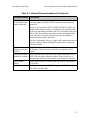
1
Copyright 2008 Dell, Inc. All rights reserved.
Dell is a trademark of Dell, Inc.
EqualLogic is a registered trademark.
All trademarks and registered trademarks mentioned herein are the property of their
respective owners.
Information in this document is subject to change without notice.
Reproduction in any manner whatsoever without the written permission of Dell is strictly
forbidden.
December 2008
Part Number: P631M Rev. A01
Table of Contents
Preface ...................................................................................................... iii
Audience .............................................................................................................. iii
Organization ........................................................................................................ iii
Documentation ......................................................................................................iv
Technical Support and Customer Service ..............................................................v
1 Steps for Getting Started............................................................................... 1-1
2 Hardware Installation ................................................................................... 2-1
Protecting Hardware ........................................................................................... 2-1
Network Requirements and Recommendations.................................................. 2-2
Installing a PS6000 Array................................................................................... 2-4
Before You Begin ........................................................................................ 2-4
Environmental Requirements ................................................................ 2-5
Shipping Box Contents and Required Hardware................................... 2-6
Rack Mount Requirements .................................................................... 2-7
Installing the Hardware ................................................................................ 2-7
Step 1: Connect the Array to Power ...................................................... 2-8
Step 2: Connect the Array to the Network ............................................ 2-9
Step 3: Turn on Power to the Array..................................................... 2-11
Step 4: Set Up a Serial Connection to the Array ................................. 2-11
Installing a PS6500 Array................................................................................. 2-14
Before You Begin ...................................................................................... 2-14
Environmental Requirements .............................................................. 2-15
Shipping Box Contents and Required Hardware................................. 2-16
Rack Mount Requirements .................................................................. 2-17
Installing the Hardware .............................................................................. 2-17
Step 1: Connect the Array to Power .................................................... 2-18
Step 2: Connect the Array to the Network .......................................... 2-22
Step 3: Turn on Power to the Array..................................................... 2-24
Step 4: Set Up a Serial Connection to the Array ................................. 2-26
3 Software Configuration................................................................................. 3-1
Step 1: Choose a Configuration Method ............................................................ 3-1
About the Remote Setup Wizard.................................................................. 3-1
About the setup Utility ................................................................................. 3-2
Step 2: Collect Configuration Information ......................................................... 3-2
i
Installation and Setup
Table of Contents
Step 3: Start the Software Configuration............................................................ 3-4
Using the setup Utility to Configure the Software....................................... 3-4
Using the Remote Setup Wizard to Configure the Software ....................... 3-7
Step 4: Set the Member RAID Policy................................................................. 3-8
Using the CLI to Set the RAID Policy......................................................... 3-8
Using the GUI to Set the RAID Policy ........................................................ 3-9
4 Storage Allocation.......................................................................................... 4-1
Step 1: Create a Volume ..................................................................................... 4-1
Using the CLI to Create a Volume............................................................... 4-2
Using the GUI to Create a Volume .............................................................. 4-3
Step 2: Connect a Computer to a Volume .......................................................... 4-5
5 Where to Go Next .......................................................................................... 5-1
Common Group Customization Tasks................................................................ 5-1
Advanced Group Administration Tasks ............................................................. 5-2
Index............................................................................................................Index-1
ii
Preface
With one or more PS Series storage arrays, you can create a PS Series group—a
self-managing, iSCSI storage area network (SAN) that is affordable and easy to
use, regardless of scale.
This manual describes how to install PS6000 and PS6500 array hardware,
configure the software, and start using the SAN.
Audience
This manual is designed for the administrators responsible for installing array
hardware. Administrators are not required to have extensive network or storage
system experience. However, it may be useful to understand:
•
Basic networking concepts
•
Current network environment
•
User disk storage requirements
•
RAID configurations
•
Disk storage management
Note: Although this manual provides examples of using PS Series arrays in some
common network configurations, detailed information about setting up a
network is beyond its scope.
Organization
This manual is organized as follows:
•
Chapter 1, Steps for Getting Started, describes the steps for getting started.
•
Chapter 2, Hardware Installation, describes how to install the array hardware.
•
Chapter 3, Software Configuration, describes how to initialize an array and
either create a group with the array as the first member or add the array to an
existing group.
iii
Installation and Setup
Preface
•
Chapter 4, Storage Allocation, describes how to create and connect to a
volume.
•
Chapter 5, Where to Go Next, describes basic and advanced group
administration tasks.
Documentation
For detailed information about PS Series arrays, groups, and volumes, see the
following documentation:
•
PS Series Release Notes. Provides the latest information about PS Series
arrays and groups.
•
Dell EqualLogic PS Series Array End User License Agreement (EULA)
•
Warranty and Support Information (WSI)
•
Safety, Environmental, and Regulatory Information (SERI)
•
PS Series Hardware Maintenance. Describes how to maintain the array
hardware. Use the manual for your array model.
•
PS Series Group Administration. Describes how to use the Group Manager
graphical user interface (GUI) to manage a PS Series group. This manual
provides comprehensive information about product concepts and procedures.
•
PS Series CLI Reference. Describes how to use the Group Manager command
line interface (CLI) to manage a PS Series group and individual arrays.
•
PS Series Online help. In the Group Manager GUI, expand Tools in the far
left panel and then click Online Help for help on both the GUI and the CLI.
Documentation for Host Integration Tools for Microsoft® Windows® includes the
following:
•
Host Integration Tools Release Notes. Provides the latest information about
the Host Integration Tools, including the Remote Setup Wizard.
•
Host Integration Tools User Guide. Describes how to install and use the Host
Integration Tools.
See support.dell.com/EqualLogic for the latest documentation.
iv
Installation and Setup
Preface
Technical Support and Customer Service
Dell's support service is available to answer your questions about PS Series
arrays. If you have an Express Service Code, have it ready when you call. The
code helps Dell's automated-support telephone system direct your call more
efficiently.
Contacting Dell
Dell provides several online and telephone-based support and service options.
Availability varies by country and product, and some services may not be
available in your area.
For customers in the United States, call 800-945-3355.
Note: If you do not have an Internet connection, you can find contact information
on your purchase invoice, packing slip, bill, or Dell product catalog.
To contact Dell for sales, technical support, or customer service issues:
1. Visit support.dell.com.
2. Verify your country or region in the Choose A Country/Region drop-down
menu at the bottom of the window.
3. Click Contact Us on the left side of the window.
4. Select the appropriate service or support link based on your need.
5. Choose the method of contacting Dell that is convenient for you.
Online Services
You can learn about Dell products and services on the following websites:
•
www.dell.com/
•
www.dell.com/ap/ (Asian/Pacific countries only)
•
www.dell.com/jp (Japan only)
•
www.euro.dell.com (Europe only)
v
Installation and Setup
•
www.dell.com/la (Latin American countries)
•
www.dell.ca (Canada only)
You can access Dell Support through the following websites:
•
support.dell.com
•
support.dell.com/EqualLogic
•
support.jp.dell.com (Japan only)
•
support.euro.dell.com (Europe only)
vi
Preface
1 Steps for Getting Started
To set up a SAN and start using your array, follow these steps:
1. Set up the PS Series array hardware configuration. This manual includes
information on connecting a PS Series array to your network and to power.
See Chapter 2, Hardware Installation.
2. Configure the PS Series software. First, initialize an array to make it
accessible on the network. Then, either create a group with the array as the
first group member or add the array to an existing group. When you expand a
group, capacity and performance increase automatically.
There are two methods for configuring the software. If you have a Windows
computer and meet the requirements, use the Remote Setup Wizard. The
setup utility is supported in all environments.
See Chapter 3, Software Configuration.
3. Start using the SAN. Allocate group storage space to users and applications
by creating volumes. A volume appears on the network as an iSCSI target.
Use a computer’s iSCSI initiator to connect to a volume. Once you connect to
a volume, it appears as a regular disk on the computer.
See Chapter 4, Storage Allocation.
After getting started, you can customize the group and use its more advanced
features. See Chapter 5, Where to Go Next.
1-1
2 Hardware Installation
The first step in using your PS Series array is to install the hardware. This chapter
contains the following general electrostatic safety and network information, and
installation information for PS6000 and PS6500 arrays:
•
Protecting Hardware on page 2-1
•
Network Requirements and Recommendations on page 2-2
•
Installing a PS6000 Array on page 2-4
•
Installing a PS6500 Array on page 2-14
After installing the array hardware, you can configure the software, as described
in Chapter 3, Software Configuration.
Protecting Hardware
Protect a PS Series array from electrostatic discharge. When handling array
hardware, make sure you use the electrostatic wrist strap that is shipped with the
array or a similar form of protection.
To use the wrist strap:
1. Connect the steel snap on the coil cord to the stud on the elastic band. See
Figure 2-1.
Figure 2-1: Using an Electrostatic Wrist Strap
2. Fit the band closely around your wrist.
3. Connect the banana plug to ground, or attach the plug to the alligator clip and
connect the clip to a grounded device such as an ESD mat or the metal frame
of a grounded piece of equipment.
2–1
Installation and Setup
Network Requirements and Recommendations
Network Requirements and Recommendations
The minimum network configuration for a PS Series array consists of a
connection between Ethernet 0 on each control module and a computer or a
network switch. To increase performance and availability, configure multiple
network interfaces on an array and connect them to multiple switches.
Network recommendations are described in Table 2-1. In addition, all the usual
rules for proper network configuration apply to PS Series arrays. General network
configuration is beyond the scope of this manual.
Table 2-1: Network Recommendations
Recommendation Description
Switched Gigabit
Ethernet network
Connect arrays and computers to a switched network and make
sure that all network connections between computers and arrays
are Gigabit Ethernet. Although an array can operate at 10 or 100
Mbits, performance will be slower than when using a Gigabit
Ethernet switch.
Multiple network
connections to
different network
switches
For increased bandwidth and availability, connect all the network
interfaces on both control modules to multiple network switches.
The switches must be connected using interswitch links. The links
must have sufficient bandwidth to handle the iSCSI traffic.
After connecting the network interfaces, use the Group Manager
GUI or CLI to assign an IP address and netmask to each interface.
Access to the group
IP address
In a multi-subnet group, each configured network interface should
have access to the subnet on which the group IP address resides.
Redundant network Use a multipathing solution to make sure that no single point of
paths between
failure exists between computers and arrays.
computers and arrays
For replication, a
reliable, adequately
sized network link
2–2
For effective and predictable replication, make sure that the
network link between the primary and secondary groups is reliable
and provides sufficient bandwidth for copying data.
Installation and Setup
Network Requirements and Recommendations
Table 2-1: Network Recommendations (Continued)
Recommendation Description
No STP functionality If possible, do not use Spanning-Tree Protocol (STP) on switch
on switch ports that ports that connect end nodes (iSCSI initiators or array network
connect end nodes
interfaces).
However, if you must use STP or RSTP (preferable to STP), you
should enable the port settings (available on some switches) that
let the port immediately transition into STP forwarding state upon
link up. This functionality can reduce network interruptions that
occur when devices restart, and it should only be enabled on
switch ports that connect end nodes.
You can use Spanning-Tree for a single-cable connection between
switches, and you can use trunking for multi-cable connections
between switches.
Flow Control
Enable Flow Control on each switch port and NIC that handles
enabled on switches iSCSI traffic. PS Series arrays will correctly respond to Flow
and NICs
Control.
Unicast storm control Disable unicast storm control on each switch that handles iSCSI
disabled on switches traffic if the switch provides this feature. However, the use of
broadcast and multicast storm control is encouraged on switches.
Jumbo Frames
enabled
Enable Jumbo Frames on each switch and each NIC that handles
iSCSI traffic.
VLANs
Configure switches to use VLANs to separate iSCSI SAN traffic
from other network traffic.
2–3
Installation and Setup
Installing a PS6000 Array
Installing a PS6000 Array
Use these instructions if you have a PS6000 array, which is a 3U array with 16
drive slots, two power supply and cooling modules, and two control modules.
Figure 2-2: PS6000 Array - Front View
Figure 2-3: PS6000 Array - Rear View
Before You Begin
You must meet these prerequisites before installing a PS6000 array:
•
Make sure the array and installation location meet the environmental
requirements. See Environmental Requirements on page 2-5.
•
Gather all the required hardware. See Shipping Box Contents and Required
Hardware on page 2-6.
•
Rack mount the array. See Rack Mount Requirements on page 2-7.
2–4
Installation and Setup
Installing a PS6000 Array
Environmental Requirements
You must meet these environmental requirements for a PS6000 array:
•
Only operate an enclosure from a power source with a voltage range of 100 to
240 VAC.
•
Make sure each power source has sufficient electrical overload protection.
•
Make sure there is sufficient space for air flow in front of and behind the
array.
•
Make sure the location is properly vented.
•
Review the technical specifications in Table 2-2 to make sure your
environment supports its requirements.
Table 2-2: PS6000 Technical Specifications
Component
Requirement
Weight of fully-loaded array
77.6 pounds or 35 kilograms
Operating temperature
41 to 95 degrees F / 5 to 35 degrees C
Storage temperature
-22 to 140 degrees F / -30 to 60 degrees C
Operating altitude
10,000 feet (3048 meters)
Operational relative humidity
20 to 80 percent non-condensing
Thermal output (fully-loaded array) 1700 BTU/hour (SAS disks)
1550 BTU/hour (SATA disks)
Operational shock
5 G for 10 ms 1/2 sin
Operational vibration
Random 0.21grms 5 - 500 Hz
Input voltage
100 to 240 VAC (auto-sensing)
Input frequency
48 - 62 Hz
System input power
530 VA (maximum)
Each power supply
450 watts DC output
Maximum input power: 0.7 KVA
Input current: 7 – 3.5A
Dimensions
5.12 in. x 19 in. x 21.7 in.
(13 cm x 48.26 cm x 55.1 cm)
2–5
Installation and Setup
Installing a PS6000 Array
Shipping Box Contents and Required Hardware
Make sure you have all the items supplied in the shipping box, described in
Table 2-3. You must also provide additional hardware that is specific to your
environment and not included in the shipping box. See Table 2-4.
Table 2-3: Description of PS6000 Shipping Box Contents
Component
Description
3U array chassis
The PS6000 array contains two Type 7 control modules (green
face plate and four Ethernet ports).
Type 7 Control Module
The array also contains two power supply and cooling modules,
and eight or 16 disks, either Serial Attached SCSI (SAS) disks
or Serial ATA (SATA) disks.
Power cables
Connects an array to power sources. The shipping box may
contain different types of power cables to meet the electrical
requirements of the country in which the array will reside. Use
the cable type that is right for your environment.
If power cables are not included in the shipping box, contact
your PS Series array support provider or reseller.
Serial cable
Creates a serial connection between an array and a console or
terminal emulator. Use the cable to run the setup utility or if
there is no network access to the array or group.
Rail assembly kit for a
four-pole rack
Enables you to mount an array in a four-pole rack. Instructions
for assembly are included in the kit.
Electrostatic wrist strap Protects sensitive hardware from electrical discharge.
Documentation
2–6
The following documentation is included in the shipping box:
• Unpacking Instructions
• Rack Mount Instructions
• Setup poster
• Installation and Setup manual
• License, regulatory, and warranty information
Installation and Setup
Installing a PS6000 Array
Table 2-4: Required Hardware – Not Supplied
Component
Description
Standard 19 in. fourpole rack
Provides easy access to arrays and other hardware in your
computing environment.
Two to eight network
cables
Connects an array to a network switch. Use Category 5E or
Category 6 cables with RJ45 connectors. Use Category 5 cables
only if they adhere to the TIA/EIA TSB95 standard.
Connect at least one port on each control module to the network
switch.
Network switch
Connects devices to a network. Multiple switches are
recommended.
Optionally, you can also use an uninterruptible power supply system (UPS) to
provide a highly available source of power to an array. Each UPS (not included)
should be on a different circuit and must provide the correct type of voltage for an
adequate amount of time.
Rack Mount Requirements
Mount the PS6000 array in a standard, 19 inch rack, according to the following
requirements:
•
Mount the array in a horizontal position. Failure to do so will void your array
warranty and support contract.
•
Attach the rack to the floor for added stability.
•
Support the array until it is completely mounted in the rack.
The rail assembly kit supplied in the array shipping box includes installation and
mounting instructions.
Installing the Hardware
Make sure you complete the preliminary tasks described in Before You Begin on
page 2-4 Then, follow these steps to install a PS6000 array:
1. Connect the power cables. Do not turn on power to the array at this time. See
Step 1: Connect the Array to Power on page 2-8.
2–7
Installation and Setup
Installing a PS6000 Array
2. Connect the array to the network. See Step 2: Connect the Array to the
Network on page 2-9.
3. Turn on power to the array. See Step 3: Turn on Power to the Array on page 211.
4. If you plan to use the setup utility to configure the software, see Step 4: Set
Up a Serial Connection to the Array on page 2-11.
If you plan to use the Remote Setup Wizard to configure the software, skip
this step.
The following sections describe the installation steps in detail. After completing
the hardware installation, see Chapter 3, Software Configuration.
Step 1: Connect the Array to Power
A PS6000 array includes two modules that supply both power and cooling. One
functioning power supply and cooling module connected to a source of power is
required for array operation.
Obtain the power cables that were shipped with the array. If the array was not
shipped with power cables, see your PS Series support provider or reseller for
power cable information.
Connect both power supply and cooling modules to a source of power. Use the
cable strain relief to secure each power cable to the array.
For increased availability, follow these power recommendations:
•
Connect the power supply and cooling modules to different sources of power
on separate circuits. See Figure 2-4.
•
Connect one power supply and cooling module to a UPS system and connect
the other module to a different source of power.
Notes: Do not turn on power to the array. At this time, the power cables are only
for grounding purposes.
See Environmental Requirements on page 2-5 for information about
voltage requirements.
2–8
Installation and Setup
Installing a PS6000 Array
Figure 2-4: Recommended Power Configuration - PS6000
Step 2: Connect the Array to the Network
The PS6000 array includes two control modules of the same type and color. Each
control module has four network interface ports, labeled from 0 to 3.
One functioning network connection is required for array operation. Multiple
network connections are recommended for performance and high availability. See
Table 2-1 for additional network recommendations.
Obtain two to eight network cables. Network cables are not included in the array
shipping box. See Table 2-4 for supported network cable types.
At a minimum, connect network cables to Ethernet 0 on both control modules and
then connect the cables to a network switch. See Figure 2-5.
2–9
Installation and Setup
Installing a PS6000 Array
Figure 2-5: Minimum Network Configuration - PS6000
For maximum network bandwidth and availability, it is recommended that you
use eight network cables to connect all the network interfaces to multiple network
switches. The switches must be connected with interswitch links that have
sufficient bandwidth. See Figure 2-6.
Figure 2-6: Recommended Network Configuration - PS6000
2–10
Installation and Setup
Installing a PS6000 Array
Step 3: Turn on Power to the Array
Before turning on power, allow sufficient time for the PS6000 to adjust to ambient
temperature (for example, overnight).
The power switch is located below the power plug on each power supply and
cooling module.
Note: Batteries will start to charge and some hardware components will start to
synchronize when power is turned on. Array LEDs may indicate this ongoing activity, which is normal array behavior.
Step 4: Set Up a Serial Connection to the Array
If you plan to use the setup utility to configure the software, you must set up a
serial connection. If you plan to use the Remote Setup Wizard, you do not need a
serial connection. See Step 1: Choose a Configuration Method on page 3-1 for
information about Remote Setup Wizard requirements.
Note: The serial cable that was shipped with the array is a standard null-modem
cable with a female DB9 connector (Figure 2-7) on each end. You might
have to make or buy an adapter cable (one DB9 connector and one RJ45
connector) to connect the array to some terminal server models. See
Table 2-5 for the DB9 to DB9 pinout information.
Figure 2-7: Serial Cable DB9 Connector - Pin Locations
Table 2-5: DB9 to DB9 Pinout Information
DB9-1
Function
DB9-2
Pin Pin Function
Receive Data
2
3
Transmit Data
Transmit Data
3
2
Receive Data
Data Terminal Ready
4
6+1 Data Set Ready + Carrier Detect
2–11
Installation and Setup
Installing a PS6000 Array
Table 2-5: DB9 to DB9 Pinout Information (Continued)
DB9-1
Function
System Ground
DB9-2
Pin Pin Function
5
5
System Ground
6+1
4
Data Terminal Ready
Request to Send
7
8
Clear to Send
Clear to Send
8
7
Request to Send
Data Set Ready + Carrier Detect
Attach the cable to the serial port on the active control module (ACT LED will be
green) and to a console terminal or a computer running a terminal emulator. See
Figure 2-8 (not to scale).
Figure 2-8: Connecting a Serial Cable to the Array
2–12
Installation and Setup
Installing a PS6000 Array
The serial connection must have the following characteristics:
•
9600 baud
•
One STOP bit
•
No parity
•
8 data bits
•
No flow control
Note: Keep the serial cable. You must use the serial cable to manage the group
or a specific array if there is no network access.
After completing the hardware installation, see Chapter 3, Software
Configuration.
2–13
Installation and Setup
Installing a PS6500 Array
Installing a PS6500 Array
Use these instructions if you have a PS6500 array, which is a 4U array with 48
drive slots, three power supply and cooling modules, and two control modules.
Figure 2-9: PS6500 Array - Front View
Figure 2-10: PS6500 Array - Rear View
Before You Begin
You must meet these prerequisites before installing a PS6500 array:
•
Make sure the array and installation location meet the environmental
requirements. See Environmental Requirements on page 2-15.
•
Gather all the required hardware. See Shipping Box Contents and Required
Hardware on page 2-16.
•
Rack mount the array. See Rack Mount Requirements on page 2-17.
2–14
Installation and Setup
Installing a PS6500 Array
Environmental Requirements
You must meet these environmental requirements for a PS6500 array:
•
Only operate an enclosure from a power source with a voltage range of 100 to
240 VAC.
•
Make sure your power source has sufficient electrical overload protection.
•
In North America, connect the enclosure to a source of power with overcurrent protection provided by a double pole 20A or less (LISTED circuit
breaker to UL489). In Europe, the over-current protection must be provided
by 20A or less (IEC circuit breakers).
•
Make sure there is sufficient space for air flow in front of and behind the array
and make sure that the location is properly vented.
•
Review the technical specifications inTable 2-6 to make sure your
environment supports its requirements.
Table 2-6: PS6500 Technical Specifications
Component
Requirement
Weight without disk drives
77 pounds (35kg)
Weight with disk drives
177 pounds (80kg)
Operating temperature
41 to 95 degrees F / 5 to 35 degrees C
Storage temperature
34 to 140 degrees F / 1 to 60 degrees C
Operating altitude
0 to 10,000 feet (0 to 3048 meters)
Operational relative humidity
20 percent to 80 percent non-condensing
Storage relative humidity
5 percent to 80 percent non-condensing
Thermal output (fully-loaded array) 3400 BTU/hour
Operational shock
5G peak 1/2 sin, for 10ms
Operational vibration
Random 0.21grms 5 - 500 Hz
Input voltage
100 to 240 VAC (auto-sensing)
Input frequency
50 - 60Hz
System input power
1400 VA (maximum)
Each power supply
440 watts DC output
Maximum input power: 0.7 KVA
Input current: 7 – 3.5A
2–15
Installation and Setup
Installing a PS6500 Array
Table 2-6: PS6500 Technical Specifications (Continued)
Component
Requirement
Dimensions
6.89 in. x 19.01 in. x 31.9 in.
(17.5 cm x 48.3 cm x 81.0 cm)
Shipping Box Contents and Required Hardware
Make sure you have all the items supplied in the shipping box, described in
Table 2-7. You must also provide additional hardware that is specific to your
environment and not included in the shipping box. See Table 2-8.
Table 2-7: PS6500 Shipping Box Contents
Component
Description
4U array chassis
Contains two Type 7 control modules (green face plate), three
power supply and cooling modules, two channel cards, and one
EIP card.
Type 7 Control Module
Disk drives
Forty-eight disk drives are stored in four separate boxes within
the shipping box. Do not remove disk drives from their
packaging until you are ready to install them.
Power cables
The shipping box may contain multiple power cables to meet
the electrical requirements of the country in which the array
will reside. Use the cable that is right for your configuration.
If power cables are not included in the shipping box, contact
your PS Series support provider or reseller.
Serial cable
Creates a serial connection between an array and a console or
terminal emulator. The cable is used to run the setup utility or
if there is no network access to the array or group.
Rail kit
Enables you to install an array in a rack. See the Rack Mount
Instructions for installation information.
Cable management
system kit
Enables you to organize power and network cables. See the
Rack Mount Instructions for installation information.
Electrostatic wrist strap Protects sensitive hardware from electrostatic discharge.
2–16
Installation and Setup
Installing a PS6500 Array
Table 2-7: PS6500 Shipping Box Contents (Continued)
Component
Description
Documentation
The following documentation is included in the shipping box:
• Unpacking Instructions
• Rack Mount Instructions
• Setup poster
• Installation and Setup manual (this document)
• License, regulatory, and warranty information
Table 2-8: Required Hardware – Not Supplied
Component
Description
Standard 19 in. fourpole rack
Provides easy access to arrays and other hardware in your
computing environment.
Two to eight network
cables
Connects an array to a network switch. Use Category 5E or
Category 6 cables with RJ45 connectors. Use Category 5 cables
only if they adhere to the TIA/EIA TSB95 standard.
Network switch
Connects devices to a network. Multiple switches are
recommended for high availability.
Optionally, you can also use an uninterruptible power supply system (UPS) to
provide a highly available source of power to an array. Each UPS (not included)
should be on a different circuit and must provide the correct type of voltage for an
adequate amount of time.
Rack Mount Requirements
You must mount an array in a standard, 19 inch rack. The Rack Mount Instructions
are included in the shipping box. The instructions include rack requirements and
steps for mounting an array in a rack, installing the disk drives and other
components, and installing the cable management system.
Installing the Hardware
Make sure you complete the preliminary tasks described in Before You Begin on
page 2-14. Then, follow these steps to install a PS6500 array:
1. Connect the power cables. Do not turn on power to the array at this time. See
Step 1: Connect the Array to Power on page 2-18.
2–17
Installation and Setup
Installing a PS6500 Array
2. Connect the array to the network. See Step 2: Connect the Array to the
Network on page 2-22.
3. Turn on power to the array. See Step 3: Turn on Power to the Array on page 224.
4. If you plan to use the setup utility to configure the software, see Step 4: Set
Up a Serial Connection to the Array on page 2-26.
If you plan to use the Remote Setup Wizard to configure the software, skip
this step.
The following sections describe the installation steps in detail. After completing
the hardware installation, see Chapter 3, Software Configuration.
Step 1: Connect the Array to Power
The PS6500 array includes three modules that supply both power and cooling. At
least two functioning power supply and cooling modules, connected to a source of
power, are required for array operation.
Note: See Environmental Requirements on page 2-15 for information about
voltage requirements.
Obtain the power cables that were shipped with the array. If the array was not
shipped with power cables, contact your PS Series support provider or reseller for
power cable information.
Note: Dell recommends that you connect the supplied 6 foot (2 m) C113/C14
power cables to the array. They are the correct length to route through the
cable management system, and are designed to connect tightly to the
power supply modules. If necessary, connect the extension 10 foot (3.3 m)
C13/C14 cables or country-specific cables to the ends of the supplied
power cables.
Connect all the power supply and cooling modules to a source of power. Use the
cable strain relief to secure each power cable to the array.
For increased availability, follow these power recommendations:
•
Connect the power supply and cooling modules to different power sources on
separate circuits. See Figure 2-11.
2–18
Installation and Setup
•
Installing a PS6500 Array
Connect two power supply and cooling modules to UPS systems and connect
the other module to a different source of power.
Figure 2-11: Recommended Power Configuration - PS6500
You must use the cable management system to organize your power (and network)
cables. The cable management system also enables you to open the chassis cover
without dislodging the cables.
The cable management system consists of two wire assemblies, as shown in
Figure 2-12:
•
One wire assembly has three arms, three clamps, and six fabric hook-and-loop
fasteners.
•
The other wire assembly has one arm, two clamps, and three fabric hook-andloop fasteners.
2–19
Installation and Setup
Installing a PS6500 Array
Figure 2-12: Cable Management System – Not Installed
The cable management system is attached to the rear of the array chassis and to
the rack rails. See Figure 2-13.
Figure 2-13: Cable Management System – Installed
See the Rack Mount Instructions for information about installing the cable
management system.
To use the cable management system:
1. Gather the power cables and route the cables along the top arm of the threearm assembly, going from to , as shown in Figure 2-14. Make sure the
2–20
Installation and Setup
Installing a PS6500 Array
cables have sufficient slack between the array back panel and the first
connection to the cable management system ( ).
Figure 2-14: Cable Routing Diagram
2. Connect all three fasteners on the arm and place the cables below the arms.
See Figure 2-15.
Figure 2-15: Attaching the Hook-and-Loop Fasteners
3. Route the cables along the middle arm of the three-arm assembly, going from
to
in Figure 2-14.
4. Route the cables along the one-arm assembly (connected to the top of the left
and right rails), going from
to
in Figure 2-14.
After routing the cables, the installation should resemble Figure 2-16.
2–21
Installation and Setup
Installing a PS6500 Array
Figure 2-16: Cables Attached to the Cable Management System
Note: Do not turn on power to the array. At this time, the power cables are only
for grounding purposes. Once you connect a power supply to a source of
power, the array will enter standby mode.
In standby mode, the array is fully grounded, and some array components
are supplied with power. For example, the power button is lit and the LCD
panel displays “standby.” However, disks and control modules are not
supplied with power, and the array is not operational.
Step 2: Connect the Array to the Network
The PS6500 array includes two control modules. Each control module has four
network interface ports, labeled Ethernet 0, Ethernet 1, Ethernet 2, and Ethernet 3.
One functioning network connection is required for array operation. Multiple
network connections are recommended for performance and high availability. See
Table 2-1 for additional network recommendations.
Obtain two to eight network cables. Network cables are not included in the array
shipping box. See Table 2-8 for supported network cable types.
At a minimum, connect network cables to Ethernet 0 on both control modules and
then connect the cables to a network switch. See Figure 2-17.
2–22
Installation and Setup
Installing a PS6500 Array
Figure 2-17: Minimum Network Configuration - PS6500
For maximum bandwidth and availability, it is recommended that you use eight
network cables to connect all the network interfaces to multiple network switches.
The switches must be connected with interswitch links that have sufficient
bandwidth. See Figure 2-18.
2–23
Installation and Setup
Installing a PS6500 Array
Figure 2-18: Recommended Network Configuration - PS6500
Use the cable management system to organize the network cables, along with the
power cables. See Figure 2-12 through Figure 2-16.
Step 3: Turn on Power to the Array
Before turning on power, allow sufficient time for the PS6500 to adjust to ambient
temperature (for example, overnight).
Turning on the power transitions the array from standby mode to full-power
mode.
The power switch is on the front of the array. To turn on power to the array you
must remove the front bezel, as follows:
1. Insert the bezel key and turn it clockwise to unlock the bezel. See Figure 2-19.
2–24
Installation and Setup
Installing a PS6500 Array
Figure 2-19: Unlocking the Bezel
2. Hold the bezel on the right side and push the bezel release latch up on the left
side to disengage the bezel from the chassis. See Figure 2-20.
Figure 2-20: Pushing Up the Bezel Release Latch
3. Pull the bezel away from the chassis. See Figure 2-21.
Figure 2-21: Detaching the Bezel from the Chassis
4. Press the blue power button on the front panel.
2–25
Installation and Setup
Installing a PS6500 Array
Note: Batteries will start to charge and some hardware components will start to
synchronize when power is turned on. Array LEDs indicate this activity,
which is normal array behavior.
To install and lock the bezel:
1. Facing the front of the rack, fit the right side of the bezel into the right side of
the chassis.
2. Push the bezel toward the chassis until the left side of the bezel engages with
the chassis.
3. Insert the bezel key and turn it counter-clockwise to lock the bezel to the
chassis.
Step 4: Set Up a Serial Connection to the Array
If you plan to use the setup utility to configure the software, you must set up a
serial connection. If you plan to use the Remote Setup Wizard, you do not need a
serial connection. See Step 1: Choose a Configuration Method on page 3-1 for
information about Remote Setup Wizard requirements.
Note: The serial cable that was shipped with the array is a standard null-modem
cable with a female DB9 connector on each end. You might have to make
or buy an adapter cable (one DB9 connector and one RJ45 connector) to
connect the array to some models of terminal server. See Figure 2-7 and
Table 2-5 on page 11 for the connector pinout information.
Attach the serial cable to the serial port on the active control module (ACT LED
will be green) and to a console terminal or a computer running a terminal
emulator. See Figure 2-22 (not to scale).
2–26
Installation and Setup
Installing a PS6500 Array
Figure 2-22: Connecting a Serial Cable to an Array
The serial connection must have the following characteristics:
•
9600 baud
•
One STOP bit
•
No parity
•
8 data bits
•
No flow control
Note: Keep the serial cable. You must use the serial cable to manage the group
or an individual array if there is no network access.
After completing the hardware installation, see Chapter 3, Software
Configuration.
2–27
3 Software Configuration
After you complete the array hardware installation, you can initialize the array
and create a PS Series group with the array as the first group member. Alternately,
you can add the array to an existing group. When you expand a group, capacity
and performance scale automatically with no impact on users.
•
Step 1: Choose a Configuration Method on page 3-1.
•
Step 2: Collect Configuration Information on page 3-2.
•
Step 3: Start the Software Configuration on page 3-4.
•
Step 4: Set the Member RAID Policy on page 3-8.
After completing the software configuration, you can allocate storage and start
using the SAN. See Chapter 4, Storage Allocation.
Step 1: Choose a Configuration Method
There are two methods for configuring the software. Choose one method:
•
Use the Remote Setup Wizard.
•
Use the setup utility.
About the Remote Setup Wizard
The Remote Setup Wizard is located on the Host Integration Tools CD-ROM
included in the shipping box and must be installed on a Windows computer. If you
meet the requirements, use the wizard. In addition to initializing an array and
creating or expanding a group, the wizard automatically:
•
Sets the RAID policy for the first group member.
•
Configures computer access to the group by specifying the group IP address
as the iSCSI discovery address and enabling Microsoft service access from
the computer to the group through CHAP authentication.
3–1
Installation and Setup
Software Configuration
The Remote Setup Wizard has the following requirements:
•
Computer running Windows XP or a higher version.
•
Connection between the array and computer. There are two options:
–
Connect the computer to the same Ethernet segment as the array, and
make sure that Layer 2 multicasting is not blocked between the array and
the computer.
–
Use an RJ45 network cable to connect the computer to Ethernet 0 on the
array’s active control module (ACT LED will be green).
About the setup Utility
The setup utility is an interactive, command line utility that prompts for
information about the array and group configuration.
To use the setup utility, you must have a serial connection between the array and
a console terminal or a computer running a terminal emulator.
After choosing a method, collect the information needed for the array
configuration.
Step 2: Collect Configuration Information
Regardless of the method you use to configure the software, you must collect the
information in Table 3-1 and Table 3-2. Obtain IP addresses from your network
administrator, as needed.
Also, make sure you follow the network recommendations in Table 2-1.
Table 3-1: Array Configuration
Prompt
Description
Member name
Unique name for the array in the group (63 or fewer letters, numbers,
or hyphens). First character must be a letter or number.
Network interface Name of an array network interface (eth0, eth1, eth2, or eth3)
that is connected to a functioning port on a network switch.
3–2
Installation and Setup
Software Configuration
Table 3-1: Array Configuration (Continued)
Prompt
Description
IP address
Network address for the array network interface.
Note:
Each member must have at least one network interface on the
same subnet as the group IP address.
Netmask
Address that combines with the IP address to identify the subnet on
which the array network interface resides (default is 255.255.255.0).
Default gateway
(optional)
Network address for the device used to connect subnets and forward
network traffic beyond the local network. A default gateway is needed
only if you want the array network interface to communicate outside
the local network (for example, to allow access to volumes from
computers outside the local network).
Note:
RAID policy
The default gateway must be on the same subnet as the array
network interface.
RAID level and spare disk drive configuration for the array. The
actual number of RAID sets and spare drives depends on the number
of drives in the array:
•
RAID 10 – Striping on top of multiple RAID 1 (mirrored) sets.
•
RAID 50 – Striping on top of multiple RAID 5 (distributedparity) sets. Each RAID 5 set has one parity drive.
•
RAID 5 – Multiple distributed-parity sets.
•
RAID 6 – Multiple dual distributed-parity sets.
Table 3-2: Group Configuration
Prompt
Description
Group name
Unique name that identifies the group (63 or fewer letters, numbers,
or hyphens). The first character must be a letter or number.
Group IP address Network address for the group. The group IP address is used for
group administration and computer access to data stored in the group.
Password for
adding members
to a group
Password required when adding members to a group. The password
must have 3 to 16 letters or numbers and is case-sensitive.
Password for the
Password that will override the factory-set group administration
password (grpadmin) for the grpadmin account. The password
must have 3 to 16 letters or numbers and is case-sensitive.
grpadmin
account
Required only when creating a new group.
3–3
Installation and Setup
Software Configuration
Table 3-2: Group Configuration
Prompt
Description
Microsoft service
user name and
password
(optional)
CHAP user name and password used to enable Microsoft service
(VSS or VDS) access to the group. The user name must have 3 to 63
alphanumeric characters. The password must have 12 to 16
alphanumeric characters, and is case-sensitive.
Microsoft services running on a computer must be allowed access to
the group in order to create VSS snapshots in the group or use VDS.
Applicable only when creating a group with the Remote Setup
Wizard.
Step 3: Start the Software Configuration
Use the setup utility or the Remote Setup Wizard to initialize the array and either
create a group with the array as the first group member or add the array to an
existing group.
After you complete the software configuration, the array becomes a member of a
group and its disk storage is available for use.
Using the setup Utility to Configure the Software
To use the setup utility to initialize an array and create or expand a group:
1. On the console or terminal emulator that has the serial connection to the array,
press the
key.
Note: If the array does not respond, contact your PS Series support provider
for information on how to proceed.
2. At the login prompt, enter grpadmin for both the account (login) name and
the password. Passwords do not appear on the screen.
3. When prompted, enter y to start the setup utility.
4. When prompted, enter the array and group configuration information from
Table 3-1 and Table 3-2. Press the
key to accept a default value. Enter a
question mark (?) to obtain help.
3–4
Installation and Setup
Software Configuration
Specify whether to create a group with the array as the first member or add the
array to an existing group.
Note: There may be a short delay after entering the group IP address as the
array searches the network.
An example of using the setup utility to initialize an array and create a group is
shown in Example 3-1.
After setup completes, you must set the member’s RAID policy in order to use
the disk storage. Go to Step 4: Set the Member RAID Policy on page 3-8.
3–5
Installation and Setup
Software Configuration
Example 3-1: Using the setup Utility
Login: grpadmin
Password: xxxxxxxx
Welcome to Group Manager
Copyright 2001 - 2008 Dell, Inc.
It appears that the storage array has not been configured.
Would you like to configure the array now? (y/n) [n] y
Group Manager Setup Utility
The setup utility establishes the initial network and storage
configuration for a storage array and then configures the array
as a member or a new or existing group of arrays.
For help, enter a question mark (?) at a prompt.
Do you want to proceed (yes | no) [no]? yes
Initializing. This may take several minutes to complete.
Enter the network configuration for the array:
Member name []: member1
Network interface [eth0]: eth0
IP address for network interface []: 192.17.2.41
Netmask [255.255.255.0]:
Default gateway [192.17.2.1]:
Enter the name and IP address of the group that the array will
join.
Group name []: group1
Group IP address []: 192.17.2.20
Searching to see if the group exists. This may take a few
minutes.
The group does not exist or currently cannot be reached. Make sure
you have entered the correct group IP address and group name.
Do you want to create a new group (yes | no) [yes]? yes
Group Configuration
Group Name:
group1
Group IP address:
192.17.2.20
Do you want to use the group settings shown above (yes | no)
[yes]: yes
Password for managing group membership:
Retype password for verification:
Password for the default group administration account:
Retype password for verification:
Saving the configuration ...
Waiting for configuration to become active......Done
Group member member1 now active in the group.
Group group1 has been created with one member.
Use the Group Manager GUI or CLI to set the RAID policy for the
member. You can then create a volume that a host can connect to
using an iSCSI initiator.
group1>
3–6
Installation and Setup
Software Configuration
Using the Remote Setup Wizard to Configure the
Software
The Remote Setup wizard is located on the Host Integration Tools CD-ROM and
must be installed on a Windows computer. The Host Integration Tools User Guide
provides detailed information about using the full capabilities of the Remote
Setup Wizard.
To run the Remote Setup Wizard, follow these steps:
1. Choose a computer that meets the requirements in Step 1: Choose a
Configuration Method on page 3-1.
2. Obtain the Host Integration Tools CD-ROM from the shipping box.
3. Insert the CD-ROM in the computer and install the Remote Setup Wizard.
4. Start the Remote Setup Wizard by clicking:
Start > Programs > EqualLogic > Remote Setup Wizard
5. In the Welcome dialog box, select Initialize a PS Series array and
click Next.
Note: If you cannot contact the array, check the network configuration. You
may need to use the setup utility to configure the software.
6. Select the array that you want to initialize and click Next.
7. In the Initialize Array dialog box, enter the array configuration from Table 3-1
and choose to create a group or join an existing group. Then, click Next.
8. In the Create a New Group or Join an Existing Group dialog box, enter the
group configuration from Table 3-2 and click Next.
9. Click Finish to exit the wizard.
If you added the array to an existing group, you must set the member’s RAID
policy in order to use the disk storage. Go to Step 4: Set the Member RAID Policy
on page 3-8.
If you created a new group, go to Chapter 4, Storage Allocation.
3–7
Installation and Setup
Software Configuration
Step 4: Set the Member RAID Policy
The storage space in a new group member (array) is not available until you
configure a RAID policy on the member. A RAID policy consists of a RAID level
and a spare disk configuration. When you select a RAID policy, the member’s
disks are automatically configured with the selected RAID level and the
appropriate number of spare disks.
If you used the Remote Setup Wizard to create a group, the RAID policy for the
first member is set according to your RAID policy selection when configuring the
software, and the storage is ready to use. See Chapter 4, Storage Allocation.
If you used the setup utility to create or expand a group, or added the array to an
existing group with the Remote Setup Wizard, you must set the RAID policy for
the group member.
Use either the Group Manager command line interface (CLI) or the graphical user
interface (GUI) to set the RAID policy.
Using the CLI to Set the RAID Policy
To use the Group Manager CLI to set the RAID policy for a new group member:
1. Log in to the group, if you are not already logged in. (After the setup utility
completes, you will still be logged in to the group.)
Use one of the following methods to connect to the group:
•
Serial connection to a member. See page 11 or page 26, depending on
•
Telnet or ssh connection to the group IP address.
your array model.
At the login prompt, enter the grpadmin account name and the password that
you specified when creating the group.
2. At the Group Manager command prompt, enter the following command:
member select member_name raid-policy policy
Specify raid50, raid5, raid10, or raid6 for the policy variable.
3–8
Installation and Setup
Software Configuration
For example, the following command configures member1 with RAID50:
group1> member select member1 raid-policy raid50
Using the GUI to Set the RAID Policy
For the latest information on browser support for the Group Manager GUI, see the
PS Series Release Notes.
To use the GUI to set the RAID policy for a member:
1. Log in to the group by entering the group IP address in a Web browser. Then,
in the login dialog box (Figure 3-1), enter the grpadmin account name and
the password that you specified when creating the group.
Figure 3-1: GUI Login
2. In the Group Summary window (Figure 3-2), expand Members in the far left
panel and select the member name.
3–9
Installation and Setup
Software Configuration
Figure 3-2: Group Summary – RAID Policy Is Not Set on Member
3. In the warning message dialog box that appears, click Yes to configure RAID
on the member.
4. In the Configure Member – General Settings dialog box (Figure 3-3), click
Next.
3–10
Installation and Setup
Software Configuration
Figure 3-3: Configure Member – General Settings
5. In the Configure Member – RAID Configuration dialog box (Figure 3-4), do
the following and then click Next.
•
Select the RAID policy.
•
Optionally, to delay using the member’s storage space until the RAID
verification completes and the batteries are fully charged, select Wait
until the member storage initialization completes. By
default, the space is immediately available, although performance will not
be optimal until the RAID verification completes.
Figure 3-4: Configure Member – RAID Configuration
3–11
Installation and Setup
Software Configuration
6. In the Configure Member – Summary dialog box (Figure 3-5), click Finish
if the member configuration is satisfactory. Click Back to make changes.
Figure 3-5: Configure Member – Summary
The array storage is ready to use.
3–12
4 Storage Allocation
Allocating group storage space to users involves the following steps:
•
Step 1: Create a Volume on page 4-1.
•
Step 2: Connect a Computer to a Volume on page 4-5.
After allocating storage, you can customize the group and use its more advanced
features. See Chapter 5, Where to Go Next.
Step 1: Create a Volume
To allocate group storage space to users and applications, use the Group Manager
CLI or GUI to create volumes. A volume appears on the network as an iSCSI
target. When you create a volume, specify the information described in Table 4-1.
Table 4-1: Volume Configuration
Component Description
Volume name This is a unique name, 63 or fewer characters (including letters, numbers,
periods, hyphens, and colons). The volume name is appended to the end of
the iSCSI target name, which is automatically generated for the volume.
Access to a volume is always through the target name.
Volume size
This is the reported size of the volume as seen by iSCSI initiators. The
minimum volume size is 15 MB. Volume sizes are rounded up to the next
multiple of 15 MB.
Access
controls
Allows computer access to a volume. A computer can access a volume
only if it matches the security credentials in a record:
•
iSCSI initiator – Restricts access to the specified initiator name.
•
IP address – Restricts access to iSCSI initiators with the specified
initiator IP address. Use asterisks for “wildcards,” if desired (for
example, 12.16.*.*). An asterisk can replace an entire octet, but it
cannot replace a digit within an octet.
At a later time, you can configure CHAP accounts in the group and use the
accounts in access control records to restrict access to volumes. See the
Group Administration manual for information.
Also specify read-write or read-only access for the volume.
4–1
Installation and Setup
Storage Allocation
Optionally, you can set aside space for volume snapshots or configure a volume
with thin provisioning. However, thin provisioning is not appropriate for all
storage environments. See the PS Series Group Administration manual for
information about advanced volume functionality.
Using the CLI to Create a Volume
1. Log in to the group.
Use one of these methods to connect to the group:
•
Serial connection to a member. See Step 4: Set Up a Serial Connection to
the Array on page 2-11 or Step 4: Set Up a Serial Connection to the Array
on page 2-26.
•
Telnet or ssh connection to the group IP address.
At the login prompt, enter the grpadmin account name and the password that
you specified when creating the group.
2. At the Group Manager command prompt, use the following command to
create the volume:
volume create volume_name size[GB]
Specify the volume name and size (the default unit of measure is megabytes).
3. Use the following command to create an access control record for the volume:
volume select volume_name access create access_control
The access_control parameter can be one or more of the following:
•
initiator initiator_name
•
ipaddress ip_address
You can create a maximum of 16 access control records for a volume.
4–2
Installation and Setup
Storage Allocation
The following example creates a 50 GB volume and one access control record.
Only a computer with the specified initiator name will be able to access the
volume.
group1> volume create staff1 50GB
group1> volume select staff1 access create initiator \
iqn.1991-05.com.microsoft:WIN2008Server.company.com
Using the GUI to Create a Volume
1. Log in to the group.
Specify the group IP address in a Web browser. Then, in the login dialog box
(Figure 3-1), enter the grpadmin account name and the password that you
specified when creating the group.
2. In the Group Summary window, click Create volume in the Activities
panel.
3. Enter the volume name and an optional description (Figure 4-1), and click
Next.
Figure 4-1: Create Volume – Volume Settings
4. Enter the volume size and click Next (Figure 4-2). The table values will
reflect the size you specify.
4–3
Installation and Setup
Storage Allocation
Figure 4-2: Create Volume – Space Reserve
5. Specify the iSCSI initiator name or IP address for the access control record
and click Next (Figure 4-3).
Figure 4-3: Create Volume – iSCSI Access
6. Review the summary information (Figure 4-4) and click Finish if the
volume configuration is correct. Click Back to make changes.
4–4
Installation and Setup
Storage Allocation
Figure 4-4: Create Volume – Summary
Step 2: Connect a Computer to a Volume
When you create a volume, the PS Series group automatically generates an iSCSI
target name, with the volume name appended to the end of the target name. Each
volume appears on the network as an iSCSI target.
An example of an iSCSI target name for a volume named dbvol is as follows:
iqn.2001-05.com.equallogic.5-4a0900-2f00000-007eca92d654f160-dbvol
To connect a computer to a volume:
1. Install and configure an iSCSI initiator on the computer. Hardware and
software initiators are available from different vendors. Configure your
initiator using the instructions provided by the vendor.
Note: Dell recommends that you visit the Technical Support website to
obtain important information about using initiators to access PS Series
group volumes.
2. Make sure that the computer matches one of the volume’s access control
records. To display the records for a volume:
4–5
Installation and Setup
•
Storage Allocation
Using the CLI, enter the following command:
volume select volume_name access show
•
Using the GUI, expand Volumes in the far-left panel, select the volume
name, and click the Access tab.
If necessary, use the CLI or the GUI to create an access control record that the
computer will match.
3. To display the iSCSI target name for the volume:
•
Using the CLI, enter the following command:
volume select volume_name show
•
Using the GUI, expand Volumes in the far-left panel, select the volume
name, and click the Connections tab.
4. On the computer, use the iSCSI initiator utility to specify the group IP address
as the iSCSI discovery address. If the initiator supports the discovery process,
it will return a list of iSCSI targets that the computer can access.
If the initiator does not support discovery, you must also specify the target
name, and, in some cases, the standard iSCSI port number (3260).
5. Use the iSCSI initiator utility to select the desired target and log in to the
target.
When the computer connects to the iSCSI target, it sees the volume as a regular
disk that can be formatted using the normal operating system utilities. For
example, you can partition the disk and create a file system.
4–6
5 Where to Go Next
After getting started, you can customize a group in order to more effectively
manage your storage environment. You can also begin to use the full set of
product features.
The PS Series Group Administration manual provides details on storage concepts
and how to use the Group Manager GUI to manage a group. The PS Series
CLI Reference manual describes how to use the Group Manager CLI to manage a
group and individual arrays.
Common Group Customization Tasks
Table 5-1 describes the common group customization tasks. These tasks are fully
documented in the PS Series Group Administration manual.
Table 5-1: Common Group Customization Tasks
Task
Description
Add network connections Multiple network connections increase performance and
to a group member
availability and are required for multipath I/O. Dell
recommends that you connect all the network interfaces on
both control modules to multiple network switches and then
use the GUI or CLI to assign an IP address and netmask to the
interfaces.
Create administration
accounts
The grpadmin account is the default administration account.
You can set up additional accounts with different privileges.
Set up event notification
To be informed of significant events in a timely manner, set up
e-mail or syslog notification.
Configure SNMP
To monitor traps from the group, you can use SNMP. In
addition, you need to configure SNMP to use the Manual
Transfer Utility and other third-party monitoring tools.
Configure iSNS.
To automate iSCSI target discovery, you can configure the
group to use an iSNS server.
Configure CHAP
accounts
You can use CHAP to restrict computer access to volumes.
Both initiator and target CHAP authentication are supported.
Modify the date, time, or Group time is based on the clock on the first member, which is
time zone or configure
set at the factory. The default time zone is EST. You can also
NTP
configure the group to use an NTP server.
5–1
Installation and Setup
Where to Go Next
Advanced Group Administration Tasks
Table 5-2 describes the advanced group administration tasks. These tasks are fully
documented in the PS Series Group Administration manual.
Table 5-2: Advanced Administration Tasks
Task
Description
Add a member to the
group
Although a one-member group is fully functional, adding
more arrays expands capacity, increases network bandwidth,
and improves overall group performance, with no disruption
to data availability.
Create pools
With multi-member groups, you can create multiple pools and
assign members and volumes to the pools for a tiered storage
solution.
Set up a dedicated
management network
You may want a separate management network for security
purposes.
Create snapshots of a
volume
Snapshots are point-in-time copies of volume data that can be
used for backups.
Create schedules for
snapshots or replicas
Schedules enable you to regularly create snapshots or replicas
of a volume.
Create collections
Collections enable you to group multiple, related volumes for
the purpose of creating snapshots or replicas. The
administrator can then create a multi-volume snapshot or a
multi-volume replica in a single operation or through a single
schedule.
Enable thin provisioning
for a volume
Some environments can benefit from thin provisioning, which
enables you to allocate space to a volume according to usage
patterns.
Set up replication across
different groups
Replicas are point-in-time copies of volume data that are
stored on a different group.
Clone a volume or
snapshot
Cloning creates a new volume in the group.
Recover data from
snapshots or replicas
There are various options for recovering data from snapshots
or replicas.
5–2
Index
A
E
access controls
protecting volumes 4-1
setting up with CLI 4-2
setting up with GUI 4-4
accounts, configuring after setup 5-1
array
initializing 3-2
network address 3-2
RAID policy 3-8
software configuration 3-1
electrostatic discharge, avoiding 2-1
electrostatic wrist strap, using 2-1
environmental requirements
PS6000 2-5
PS6500 2-15
event notification, configuring 5-1
B
bezel
installing,PS6500 2-26
removing, PS6500 2-24
C
cable (serial)
required characteristics 2-27
cable management system 2-17
CHAP accounts, configuring 5-1
CLI
creating volumes 4-2
setting RAID policy 3-8
connecting network cables
PS6000 2-9
PS6500 2-22
connecting power cables
PS6000 2-8
PS6500 2-18
control modules
PS6000 2-6
PS6500 2-16
D
date, setting 5-1
F
Flow Control recommendation 2-3
full-power mode, defined 2-24
G
Gigabit Ethernet recommendation 2-2
group
accessing volumes from a
computer 4-6
advanced tasks 5-1
creating 3-1, 3-2
customizing after setup 5-1
expanding 3-1, 3-2
IP address 3-3
logging in to CLI 3-8
logging in to GUI 3-9
name 3-3
GUI
creating volumes 4-3
setting RAID policy 3-8, 3-9
H
hardware installation
PS6000 2-4, 2-7
PS6500 2-14, 2-17
hardware requirements
PS6000 2-6
PS6500 2-16
Host Integration Tools, description 3-7
Index-1
Installation and Setup
hosts
Flow Control recommendation 2-3
Jumbo Frames recommendation
2-3
I
initiator (iSCSI)
accessing a volume 4-6
computer requirements 4-6
installing the bezel
PS6500 2-26
iSNS, configuring 5-1
J
Jumbo Frames recommendation 2-3
L
login
CLI method 3-8
GUI method 3-9
M
member
default gateway 3-2
naming 3-2
netmask 3-3
network address 3-2
RAID policy 3-8
N
netmask, member setting 3-3
Index-2
Index
network
array IP address 3-2
configuring multiple interfaces 5-1
group IP address 3-3
improving performance 2-2
recommendations 2-2
requirements 2-2
network cables
connecting, PS6000 2-9
connecting, PS6500 2-22
network configurations
PS6000 2-9
PS6500 2-22
network interfaces
configuring 3-2
NTP server, configuring 5-1
P
power cables
PS6000 2-8
PS6500 2-18
power requirements
PS6000 2-5, 2-8
PS6500 2-15
power, turning on
PS6000 2-11
PS6500 2-24
PS Series array
increasing bandwidth 2-2
multipath I/O recommendation 2-2
network recommendations 2-2
network requirements 2-2
protecting from discharge 2-1
subnet access recommendation 2-2
Installation and Setup
PS6000
connecting network cables 2-9
connecting power cables 2-8
connecting the serial cable 2-11
control modules 2-6
environmental requirements 2-5
hardware installation 2-7
hardware requirements 2-6
installing 2-4
network cables 2-9
network configurations 2-9
network requirements 2-9
power requirements 2-5
powering on 2-11
rack mount requirements 2-7
shipping box contents 2-6
technical specifications 2-5
PS6500
connecting network cables 2-22
connecting power cables 2-18
connecting the serial cable 2-26
control modules 2-16
environmental requirements 2-15
hardware installation 2-14
hardware requirements 2-16
installing 2-17
network cables 2-22
network configurations 2-22
network requirements 2-22
power requirements 2-15, 2-18
powering on 2-24
rack mount requirements 2-17
shipping box contents 2-16
technical specifications 2-15
R
rack mount requirements
PS6000 2-7
PS6500 2-17
RAID levels, supported 3-8
Index
RAID policy
description 3-8
setting with CLI 3-8
setting with GUI 3-9
recommended power configuration
2-19
Remote Setup Wizard
configuring the software 3-7
description 3-1
requirements 3-1
removing the bezel
PS6500 2-24
S
serial cable
characteristics 2-11
pin locations 2-11
pinout information 2-11
serial cable, connecting
PS6000 2-11
PS6500 2-26
setup utility
configuring the software 3-4
description 3-2
requirements 3-2
shipping box contents
PS6000 2-6
PS6500 2-16
snapshots, reserving space 4-2
SNMP, configuring 5-1
software configuration, methods 3-2
Spanning-Tree recommendation 2-3
standby mode, defined 2-22
switches
bandwidth requirement 2-10, 2-23
Flow Control recommendation 2-3
Jumbo Frames recommendation
Index-3
Installation and Setup
2-3
link recommendation 2-10, 2-23
Spanning-Tree recommendation
2-3
unicast storm control
recommendation 2-3
VLAN recommendation 2-3
T
target (iSCSI)
connecting to 4-6
obtaining name 4-6
technical specifications
PS6000 2-5
PS6500 2-15
thin provisioning, enabling on a
volume 4-2
time, setting 5-1
Index-4
Index
U
unicast storm control recommendation
2-3
V
VLAN recommendation 2-3
volumes 4-1
access controls 4-1
accessing from a computer 4-6
connecting to 4-5
creating 4-1
creating with CLI 4-2
creating with GUI 4-3
naming 4-1
reported size 4-1
snapshot space 4-2
target name for 4-6
thin provisioning settings 4-2