1
AIR-COOLED SPLIT-TYPE DUCTED AIR CONDITIONERS
DATA BOOK
Series :
PEH
HEAT PUMP : Model PEH-7, 8, 10MYB
CONTENTS
SAFETY PRECAUTIONS ----------------------------------------------2
LINE UP --------------------------------------------------------------------4
MODEL-DESIGNATION BREAKDOWN----------------------------5
SPECIFICATIONS -------------------------------------------------------6
ELECTRICAL DATA------------------------------------------------------7
SELECTION PROCEDURE -------------------------------------------8
CAPACITY TABLES ----------------------------------------------------10
OPERATION RANGE--------------------------------------------------19
FAN PERFORMANCE-------------------------------------------------20
SOUND DATA------------------------------------------------------------21
OUTLINE DIMENSIONS----------------------------------------------22
CENTER OF GRAVITY (Outdoor unit) ----------------------------24
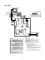
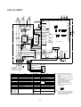
WIRING DIAGRAMS---------------------------------------------------25
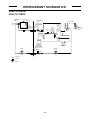
REFRIGERANT SCHEMATICS-------------------------------------28
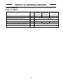
SAFETY & CONTROL DEVICES ----------------------------------29
OPTION -------------------------------------------------------------------30
INSTALLATION ----------------------------------------------------------31
TEST RUN----------------------------------------------------------------45
STANDARD OPERATION DATA ------------------------------------48
SERVICE DATA ---------------------------------------------------------49
INSTRUCTIONS FOR USE ------------------------------------------75
SPECIFICATION GUIDELINES-------------------------------------79
Specifications subject to change without notice.
-1-
SAFETY PRECAUTIONS
•
1.1. Before installation and electric work
s Before installing the unit, make sure you read all the “Safety
precautions”.
•
•
s The “Safety precautions” provide very important points regarding safety. Make sure you follow them.
•
Symbols used in the text
•
Warning:
Describes precautions that should be observed to prevent danger of injury
or death to the user.
•
•
Caution:
Describes precautions that should be observed to prevent damage to the
unit.
1.2. Before Installation
Symbols used in the illustrations
Caution:
: Indicates an action that must be avoided.
•
: Indicates that important instructions must be followed.
•
: Indicates a part which must be grounded.
: Beware of electric shock. <Color: yellow>
•
Warning:
Carefully read the labels affixed to the unit.
•
Warning:
•
•
•
•
•
•
•
•
•
•
•
•
•
•
•
Do not reconstruct or change the settings of the protection devices.
- If the pressure switch, thermal switch, or other protection device is shorted
and operated forcibly, or parts other than those specified by Mitsubishi Electric are used, fire or explosion may result.
To dispose of this product, consult your dealer.
The installer and system specialist shall secure safety against leakage
according to local regulation or standards.
- Following standards may be applicable if local regulation are not available.
Pay a special attention to the place, such as a basement, etc. where refrigeration gas can stay, since refrigeration is heavier than the air.
The appliance is not intended for use by young children or infirm persons without supervision.
Young children should be supervised to ensure that they do not play
with the appliance.
Never operate in open phase condition.
Control box may be broken.
Ask the dealer or an authorized technician to install the air conditioner.
- Improper installation by the user may result in water leakage, electric shock,
or fire.
Install the unit at a place that can withstand its weight.
- Inadequate strength may cause the unit to fall down, resulting in injuries.
Use the specified cables for wiring. Make the connections securely so
that the outside force of the cable is not applied to the terminals.
- Inadequate connection and fastening may generate heat and cause a fire.
Prepare for strong winds and earthquakes and install the unit at the specified place.
- Improper installation may cause the unit to topple and result in injury.
Always use an filter and other accessories specified by Mitsubishi Electric.
- Ask an authorized technician to install the accessories. Improper installation
by the user may result in water leakage, electric shock, or fire.
Never repair the unit. If the air conditioner must be repaired, consult the
dealer.
- If the unit is repaired improperly, water leakage, electric shock, or fire may
result.
Do not touch the heat exchanger fins and metal edges.
- Improper handling may result in injury.
If refrigerant gas leaks during installation work, ventilate the room.
- If the refrigerant gas comes into contact with a flame, poisonous gases will
be released.
Install the air conditioner according to this Installation Manual.
- If the unit is installed improperly, water leakage, electric shock, or fire may
result.
Have all electric work done by a licensed electrician according to “Electric Facility Engineering Standard” and “Interior Wire Regulations”and
the instructions given in this manual and always use a special circuit.
- If the power source capacity is inadequate or electric work is performed improperly, electric shock and fire may result.
Securely install the terminal cover (panel).
- If the terminal cover (panel) is not installed properly, dust or water may enter
the outdoor unit and fire or electric shock may result.
When installing and moving the air conditioner to another site, do not
charge the it with a refrigerant different from the refrigerant (R22) specified on the unit.
- If a different refrigerant or air is mixed with the original refrigerant, the refrigerant cycle may malfunction and the unit may be damaged.
If the air conditioner is installed in a small room, measures must be taken
to prevent the refrigerant concentration from exceeding the safety limit
even if the refrigerant should leak.
- Consult the dealer regarding the appropriate measures to prevent the safety
limit from being exceeded. Should the refrigerant leak and cause the safety
limit to be exceeded, hazards due to lack of oxygen in the room could result.
When moving and reinstalling the air conditioner, consult the dealer or
an authorized technician.
- If the air conditioner is installed improperly, water leakage, electric shock, or
fire may result.
After completing installation work, make sure that refrigerant gas is not
leaking.
- If the refrigerant gas leaks and is exposed to a fan heater, stove, oven, or
other heat source, it may generate noxious gases.
•
Do not install the unit where combustible gas may leak.
- If the gas leaks and accumulates around the unit, an explosion may result.
Do not use the air conditioner where food, pets, plants, precision instruments, or artwork are kept.
- The quality of the food, etc. may deteriorate.
Do not use the air conditioner in special environments.
- Oil, steam, sulfuric smoke, etc. can significantly reduce the performance of
the air conditioner or damage its parts.
When installing the unit in a hospital, communication station, or similar
place, provide sufficient protection against noise.
- The inverter equipment, private power generator, high-frequency medical
equipment, or radio communication equipment may cause the air conditioner
to operate erroneously, or fail to operate. On the other hand, the air conditioner may affect such equipment by creating noise that disturbs medical
treatment or image broadcasting.
Do not install the unit on a structure that may cause leakage.
- When the room humidity exceeds 80 % or when the drain pipe is clogged,
condensation may drip from the indoor unit. Perform collective drainage work
together with the outdoor unit, as required.
1.3. Before Installation (moved) - electrical
work
Caution:
•
•
•
•
•
•
•
•
•
•
•
-2-
Ground the unit.
- Do not connect the ground wire to gas or water pipes, lightning rods, or
telephone ground lines. Improper grounding may result in electric shock.
The reverse phase of L lines (L1, L2, L3) can be detected (Error cord: 4103),
but the reverse phase of L lines and N line can be not be detected.
- Some electric parts should be damaged when power is supplied under the
miss wiring.
Install the power cable so that tension is not applied to the cable.
- Tension may cause the cable to break and generate heat and cause a fire.
Install an leak circuit breaker, as required.
- If an leak circuit breaker is not installed, electric shock may result.
Use power line cables of sufficient current carrying capacity and rating.
- Cables that are too small may leak, generate heat, and cause a fire.
Use only a circuit breaker and fuse of the specified capacity.
- A fuse or circuit breaker of a larger capacity or a steel or copper wire may
result in a general unit failure or fire.
Do not wash the air conditioner units.
- Washing them may cause an electric shock.
Be careful that the installation base is not damaged by long use.
- If the damage is left uncorrected, the unit may fall and cause personal injury
or property damage.
Install the drain piping according to this Installation Manual to ensure
proper drainage. Wrap thermal insulation around the pipes to prevent
condensation.
- Improper drain piping may cause water leakage and damage to furniture
and other possessions.
Be very careful about product transportation.
- Only one person should not carry the product if it weighs more than 20 kg.
- Some products use PP bands for packaging. Do not use any PP bands for a
means of transportation. It is dangerous.
- Do not touch the heat exchanger fins. Doing so may cut your fingers.
- When transporting the outdoor unit, suspend it at the specified positions on
the unit base. Also support the outdoor unit at four points so that it cannot
slip sideways.
Safely dispose of the packing materials.
- Packing materials, such as nails and other metal or wooden parts, may cause
stabs or other injuries.
- Tear apart and throw away plastic packaging bags so that children will not
play with them. If children play with a plastic bag which was not torn apart,
they face the risk of suffocation.
•
Remote controller is not allowed to install for the place where direct
sunshine strikes.
1.4. Before starting the test run
Caution:
•
•
•
•
•
•
•
•
Turn on the power at least 12 hours before starting operation.
- Starting operation immediately after turning on the main power switch can
result in severe damage to internal parts. Keep the power switch turned on
during the operational season.
Do not touch the switches with wet fingers.
- Touching a switch with wet fingers can cause electric shock.
Do not touch the refrigerant pipes during and immediately after operation.
- During and immediately after operation, the refrigerant pipes are may be
hot and may be cold, depending on the condition of the refrigerant flowing
through the refrigerant piping, compressor, and other refrigerant cycle parts.
Your hands may suffer burns or frostbite if you touch the refrigerant pipes.
Do not operate the air conditioner with the panels and guards removed.
- Rotating, hot, or high-voltage parts can cause injuries.
Do not turn off the power immediately after stopping operation.
- Always wait at least five minutes before turning off the power. Otherwise,
water leakage and trouble may occur.
Do not operate the air conditioner without the air filter set place.
- Dust may accumulate, and cause a failure.
At emergency (if you smell something burning), stop operation and turn
the power source switch off.
- Continuing the operation without eliminating the emergency state may cause
a machine trouble, fire, or electric shock.
Remote controller should be pushed with finger.
- It occasionally causes the electric shock and the breakdown.
-3-
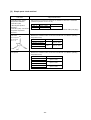
LINE UP
Cooling capacity
(gross)
Heating capacity
PEH-7MYB
PEH-8MYB
PEH-10MYB
kW
18.8
22.0
28.8
Btu/h
64,200
75,100
98,300
kcal/h
16,200
19,000
24,800
kW
20.1
22.0
28.8
Btu/h
68,600
75,100
98,300
kcal/h
17,300
19,000
24,800
Cooling: Indoor:27°CDB, 19°CWB; Outdoor: 35°CDB
Heating: Indoor:20°CDB; Outdoor: 7°CDB, 6°CWB
Cooling and Heating capacities are based 5m pipe length
-4-
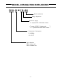
MODEL-DESIGNATION BREAKDOWN
P E H - 10 M Y B -EU
Service reference
Design Sequence
Electrical Supply
Y = 3 phase 380~415V 50Hz 4 wires
of PEH-7, 8 Indoor unit
( InY =case
1 phase 220~240V 50Hz 2 wires )
Compressor Horsepower
7 = 7 HP
8 = 7.5 HP
10= 10 HP
Series Number
PEH = Indoor unit
PUH = Outdoor unit
-5-
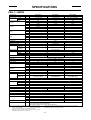
SPECIFICATIONS
PEH-7~10MYB
Model name
Service reference
indoor
Power supply
outdoor
PEH-7MYB
PEH-7MYB-EU
PEH-8MYB
PEH-8MYB-EU
PEH-10MYB
PEH-10MYB-EU
~ 220~240V 50Hz
3N~ 380~415V 50Hz
18.8
64,200
~ 220~240V 50Hz
3N~ 380~415V 50Hz
22.0
75,100
16,200
19,000
18.7
63,800
16,100
3N~ 380~415V 50Hz
3N~ 380~415V 50Hz
28.8
98,300
24,800
24.8
84,600
21,400
21.1
72,000
18,200
22.0
75,100
19,000
27.7
94,500
23,900
28.8
98,300
24,800
Total cooling capacity
(Gross)
kW
BTU/h
kcal/h
Sensible cooling capacity
(Gross)
kW
BTU/h
kcal/h
16.2
55,300
Total cooling capacity
(Net)
kW
BTU/h
kcal/h
kW
BTU/h
kcal/h
18.1
61,800
Total heating capacity
(Net)
Capacity step
Refrigerant
Refrigerant charge
kg
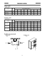
Service
reference
Height
Width
Depth
Net weight
Indoor coil
Indoor fan
Indoor fan motor
Motor output
Indoor fan air flow (Lo/Hi)
External static
pressure
Sound pressure level
Drain connection
Model name
Outdoor unit
mm
mm
mm
kg
kw
CMM
CFM
L/S
mmAq
Pa
dB(A)
mm
Service
reference
External finish
Color
Dimension
Height
Width
Depth
Net weight
Compressor
Motor output
Outdoor coil
Outdoor fan
Outdoor fan motor
Motor output
Outdoor fan air flow
Sound pressure level (cool/heat)
Protection devices
15,600
20.1
68,600
17,300
0-100
R-22
6.6
Capillary tube
%
Refrigerant control
Indoor Unit
Model name
External finish
Dimension
14,000
5.7
PEH-7MYB
PEH-8MYB
PEH-10MYB
PEH-7MYB-EU
PEH-8MYB-EU
PEH-10MYB-EU
Galvanized steel
428
kw
CMM
CFM
L/S
dB(A)
1,580
1,380
650
70
67
Cross fin coil
Centrifugal (plastic) - Direct drive
Single phase induction motor
0.4
0.21
48/60
56/70
1,695/2,119
1,978/2,472
933/1,167
800/1,000
12.5
125
55
56
25.4
84
Three phase induction motor
1.0
90
3,179
1,500
15
150
59
PUH-7MYF
PUH-8MYF
PUH-10MYF
PUH-7MYF-EUS
PUH-8MYF-EUS
PUH-10MYF-EUS
Acrylic resin coating
Munsell 5Y 8/1
1,480
1,180
550 (❈1 ; +92 <airoutlet guide>)
188 (❈1 ; +5 <airoutlet guide>)
mm
mm
mm
kg
kw
9.9
Hermetic line start
5.5
Cross fin coil
5.0
Propeller-direct drive
Three phase induction motor
2 X 0.09
167
5,898
2,783
59/59
High pressure switch, freeze & frost protection, fuse.
Over current relay (comp. & indoor fan)
Internal thermostat (comp. & indoor fan & outdoor fan )
Note 1. Cooling and heating capacitiies are based on the following conditions.
Cooling : Indoor:27°CDB, 19°CWB
; Outdoor:35°CDB.
Heating : Indoor:20°CDB,
; Outdoor:7°CDB, 6°CWB.
Cooling and heating capacities are based 5m pipe length.
2. Refergirant charge volumes are factory charged (at 5m piping length).
Refrigerant is enclosed with the outdoor unit.
221 (❈1 ; +5 <airoutlet guide>)
7.5
2 X 0.15
190
6,711
3,167
59/60
3. The measuring point of the sound pressure level is 1m from the unit front surface.
4. (❈1) value is shown with air outlet guide model.
5. Specification subject to change without notice.
-6-
ELECTRICAL DATA
PEH-7,8,10MYB
Cooling
TOTAL INPUT
TOTAL RUN CURRENT
POWER FACTOR
START CURRENT
kW
A
%
A
PEH-7MYB
PUH-7MYF
7.2
15.0
69.0
COMPRESSOR INPUT
RUN CURRENT
INDOOR side External static pressure
O/D FAN INPUT
RUN CURRENT
I/D FAN INPUT
RUN CURRENT
kW
A
Pa
kW
A
kW
A
6.31
11.5
125
0.19
0.46
0.7
3.0
7.51
13.5
125
0.19
0.45
0.89
4.0
9.55
16.9
150
0.25
0.75
1.12
1.8
TOTAL INPUT
TOTAL RUN CURRENT
POWER FACTOR
START CURRENT
kW
A
%
A
7.2
15.2
69.0
8.6
18.0
71.0
10.9
19.6
80%
77.0
COMPRESSOR INPUT
RUN CURRENT
INDOOR side External static pressure
O/D FAN INPUT
RUN CURRENT
I/D FAN INPUT
RUN CURRENT
kW
A
Pa
kW
A
kW
A
6.31
11.6
125
0.19
0.46
0.7
3.1
7.51
13.5
125
0.19
0.45
0.89
4.0
9.55
17.0
150
0.25
0.75
1.12
1.8
TOTAL INPUT
TOTAL RUN CURRENT
POWER FACTOR
START CURRENT
kW
A
%
A
7.2
15.4
69.0
8.6
18.2
71.0
10.9
19.8
84%
77.0
COMPRESSOR INPUT
RUN CURRENT
INDOOR side External static pressure
O/D FAN INPUT
RUN CURRENT
I/D FAN INPUT
RUN CURRENT
kW
A
Pa
kW
A
kW
A
6.31
11.7
125
0.19
0.47
0.7
3.2
7.51
13.6
125
0.19
0.46
0.89
4.1
9.55
17.1
150
0.25
0.75
1.12
1.9
TOTAL INPUT
TOTAL RUN CURRENT
POWER FACTOR
START CURRENT
kW
A
%
A
PEH-7MYB
PUH-7MYF
6.8
14.3
69.0
PEH-8MYB
PUH-8MYF
7.1
15.9
71.0
PEH-10MYB
PUH-10MYF
8.8
16.8
72%
77.0
COMPRESSOR INPUT
RUN CURRENT
INDOOR side External static pressure
O/D FAN INPUT
RUN CURRENT
I/D FAN INPUT
RUN CURRENT
kW
A
Pa
kW
A
kW
A
5.91
10.8
125
0.19
0.46
0.7
3.0
6.01
11.4
125
0.19
0.45
0.89
4.0
7.45
14.3
150
0.25
0.7
1.12
1.8
TOTAL INPUT
TOTAL RUN CURRENT
POWER FACTOR
START CURRENT
kW
A
%
A
6.8
14.4
69.0
7.1
15.9
71.0
8.8
16.8
74%
77.0
COMPRESSOR INPUT
RUN CURRENT
INDOOR side External static pressure
O/D FAN INPUT
RUN CURRENT
I/D FAN INPUT
RUN CURRENT
kW
A
Pa
kW
A
kW
A
5.91
10.8
125
0.19
0.46
0.7
3.1
6.01
11.4
125
0.19
0.45
0.89
4.0
7.45
14.3
150
0.25
0.7
1.12
1.8
TOTAL INPUT
TOTAL RUN CURRENT
POWER FACTOR
START CURRENT
kW
A
%
A
6.8
14.5
69.0
7.1
16.0
71.0
8.8
16.9
78%
77.0
COMPRESSOR INPUT
RUN CURRENT
INDOOR side External static pressure
O/D FAN INPUT
RUN CURRENT
I/D FAN INPUT
RUN CURRENT
kW
A
Pa
kW
A
kW
A
5.91
10.8
125
0.19
0.47
0.7
3.2
6.01
11.4
125
0.19
0.46
0.89
4.1
7.45
14.3
150
0.25
0.7
1.12
1.9
VOLT
PEH-7,8
240V
PEH-10
PUH-7~10
415V
PEH-7,8
230V
PEH-10
PUH-7~10
400V
PEH-7,8
220V
PEH-10
PUH-~10
380V
ITEM
PEH-8MYB
PUH-8MYF
8.6
18.0
71.0
PEH-10MYB
PUH-10MYF
10.9
19.5
78%
77.0
Heating
VOLT
PEH-7,8
240V
PEH-10
PUH-7~10
415V
PEH-7,8
230V
PEH-10
PUH-7~10
400V
PEH-7,8
220V
PEH-10
PUH-7~10
380V
ITEM
-7-
SELECTION PROCEDURE
1. Model Selection (With actual examples)
First step, to select the approximate model:
Based on the cooling load and the cooling capacity listed in the capacity table, select the applicable model.
Second step, to select the model:
To select the model, the following conditions must be known:
(1) Total cooling load or sensible cooling load
(2) Indoor conditioned temperature (WB*1, DB)
(3) Designed outdoor temperature (DB)*2
(4) Designed air flow
(5) Designed external static pressure (= Wind pressure loss of air duct)*3
Notes:
*1. The correct WB is required since it has a serious effect on the capacity.
*2. The cooling capacity decreases as the outdoor temperature increases. Therefore, the estimated highest
temperature during an air conditioning time frame is the "designed outdoor temperature". However, it is
recommended that the abnormal outdoor temperature which may occur once or twice a year be excluded from
the calculation to avoid selection of an excessively large capacity model.
*3. The wind pressure loss of an air duct should be calculated correctly. If a value having an excessive allowance is
used, an excessively large model will be selected. Moreover, an excessively high air flow will be induced during
actual operation causing the generation of high operating sounds and carry-over of condensed water.
(Step-1) Confirmation of operation range
Confirm that the conditions given above for the model to be selected are within the operation
range listed on Page 19.
(Step-2) Calculation of actual air flow, external static pressure, and fan motor input
Based on the designed air flow and external static pressure, obtain the actual air flow, actual
external static pressure, and fan motor power input from the fan performance table for the model
selected. For an explanation of how to use the fan performance table, see the following
examples.
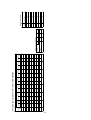
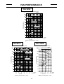
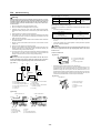
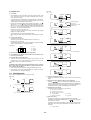
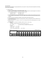
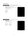
Total static pressure
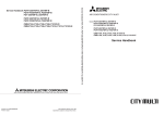
Example: PEH-8MYB, 50Hz
Example 1. (To operate with values near to the designed air flow and external static pressure.)
Condition : Designed air flow 70CMM
Fan Performance Curve 50Hz
(Pa)
Designed external static pressure 60Pa
450
Recommended Range
Calculation : The designed point is A. Therefore, duct
400
resistance line passing A is dotted line.
For Hi speed
operation line
Therefore, actual point is B for Hi speed
350
operation line
B
300
Actual air flow = 77CMM
For Low speed
operation line
Actual external static pressure = 70Pa
A
250
60Pa
Note:
Duct resustance line is secondary curve.
1400
1300
1200
1100
200
1000
150
100
Fan speed
(rpm)
l SP
rna
Inte
900
50
800
0
50
833
-8-
55
917
60
1,000
65
1,083
Air flow
70
1,167
75 77 80 (CMM)
1,250 1,283 1,333 (L/S)
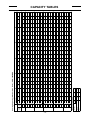
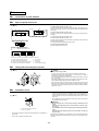
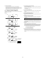
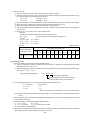
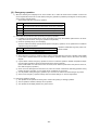
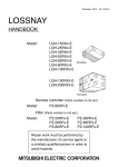
(Step-3) Calculation of net capacity
Based on the indoor conditioned temperature (WB,DB), designed outdoor temperature (DB), and the
actual air flow obtained in Step-2, obtain the gross capacity from the gross capacity tables (pages 10,
11, 13, 14, 16, 17). Then, calculate the net capacity from the formula below by using the fan motor
input obtained in Step-2.
Net capacity (kW) = Gross capacity (kW) - Fan motor input (kW)
Example: PEH-8MYB
Condition: Cooling
Indoor conditioned temp. : 26˚CDB, 19˚CWB
Designed outdoor temp. : 40˚CDB
Actual air flow : 77CMM
Fan motor input : 0.89kW (See P.7)
Calculation :
The sections of the gross capacity table applicable
for the above conditions are shown right.
OUTDOOR DB˚C
INDOOR INDOOR
DB˚C
SHC kW
SHF
T/I kW
19
21.0
16.2
0.77
9.2
Factor for Various Air Flow
PEH-8MYB
AIR VOLUME
COOLING
CAPACITY
TOTAL INPUT
CMM
60
70
80
L/S
1,000
0.976
0.991
1,167
1.0
1.0
1,330
1.025
1.009
21.4(kW)
SHC = 16.2 ✕ (1+(1.044 - 1.0) ✕ 7/10*)
T/I = 9.2 ✕ (1+(1.009-1.0))✕ 7/10*)
Q kW
26
At 26˚CDB, 19˚CWB of Indoor,
Q = 21.0, SHC = 16.2, T/I = 9.2
Therefore, when air flow is 77(CMM)
Q = 21.0 ✕ (1+(1.025 - 1.0) ✕ 7/10*)
40.0
WB˚C
16.7(kW)
9.3(kW)
Note * : 7/10 = (77-70)/(80-70)
Therfore, the net capacity is,
Net total cooling capacity = 21.4 (kw) - 0.89(kW)
= 20.51 (kW)
Net sensible cooling capacity = 16.7 (kW) - 0.89 (kW)
= 15.81 (kW)
2. Efficiency Calculation
• Refrigerant cycle energy efficienty
• System energy efficienty
(1) COP =
Gross total cooling capacity (kW)
Compressor input (kW)
(1) COP =
Net cooling capacity (kW)
Compressor input (kW)
(2) EER =
Gross total cooling capacity (kW)
Total input (kW)
(2) EER =
Net cooling capacity (kW)
Total input (kW)
1kW = 3412Btu/h
Notes:
1. COP : Coefficient of performance
2. EER : Energy efficiency ratio
3. Temperature condition of COP, EER (ARI Standard Ratings)
Indoor entering air temp. : 80˚FDB (=27˚CDB), 66˚FWB(=19˚CWB)
Outdoor entering air temp. : 95˚FDB (=35˚CDB)
4. Total input = Compressor input + Indoor fan motor input + Outdoor fan motor input (page 7).
-9-
- 10 -
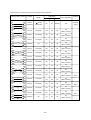
23. 5
21. 4
22. 2
22. 9
23. 5
24. 1
24. 6
22. 2
22. 9
23. 5
24. 1
24. 6
25. 2
22. 9
23. 5
21
18
19
20
21
22
23
19
20
21
22
23
24
20
21
25. 2
22. 9
20
24
22. 2
19
24. 6
21. 4
18
23
20. 9
17
24. 1
20. 3
22
1 0. 9
22. 2
19
16
1 3. 1
1 4. 5
1 5. 6
1 6. 9
1 7. 9
1 1. 1
1 2. 3
1 3. 5
1 4. 6
1 6. 1
1 0. 1
1 7. 3
1 1. 3
1 2. 7
1 3. 8
1 5. 1
1 6. 1
1 0. 3
1 1. 7
1 2. 9
1 3. 9
1 5. 2
1 6. 6
1 2. 0
21. 4
1 3. 1
1 4. 4
1 5. 6
18
20. 3
16
20. 9
19. 7
15
1 0. 9
17
20. 9
17
1 2. 2
1 3. 4
kW
SHC
60
1.0
1.0
0.989
1,000
0.975
L/S
0 .5 2
0 .5 9
0 .6 5
0 .7 2
0 .7 8
0 .4 4
0 .5 0
0 .5 6
0 .6 2
0 .7 0
0 .4 1
0 .7 8
0 .4 7
0 .5 4
0 .6 0
0 .6 8
0 .7 5
0 .4 4
0 .5 1
0 .5 8
0 .6 5
0 .7 3
0 .8 2
0 .4 9
0 .5 6
0 .6 3
0 .7 1
0 .7 9
0 .5 2
0 .6 0
0 .6 8
SHF
inpu t
50
833
CMM
-5.0
capacity
Air volume
Factor for various air flow(Cooling)
30
28
26
24
22
20. 3
19. 7
15
16
WB°C
DB°C
20
kW
Indoor
Indoor
Q
Outdoor DB°C
1.009
1.024
1,167
70
6 .1
6 .0
5 .8
5 .7
5 .6
6 .1
6 .0
5 .8
5 .7
5 .6
6 .0
5 .5
5 .8
5 .7
5 .6
5 .5
5 .4
5 .7
5 .6
5 .5
5 .4
5 .4
5 .4
5 .5
5 .4
5 .4
5 .4
5 .3
5 .4
5 .4
5 .3
kW
T/I
25.1
24.5
24.0
23.4
22.8
25.1
24.5
24.0
23.4
22.8
24.5
22.1
24.0
23.4
22.8
22.1
21.3
23.4
22.8
22.1
21.3
20.8
20.2
22.1
21.3
20.8
20.2
19.6
20.8
20.2
19.6
kW
Q
13. 1
14. 5
15. 6
16. 9
17. 8
11. 0
12. 3
13. 4
14. 5
16. 0
10. 1
17. 2
11. 3
12. 6
13. 7
15. 0
16. 0
10. 3
11. 6
12. 8
13. 9
15. 2
16. 6
10. 8
11. 9
13. 1
14. 3
15. 5
10. 8
12. 1
13. 4
kW
SHC
0. 0
0 .5 2
0 .5 9
0 .6 5
0 .7 2
0 .7 8
0 .4 4
0 .5 0
0 .5 6
0 .6 2
0 .7 0
0 .4 1
0 .7 8
0 .4 7
0 .5 4
0 .6 0
0 .6 8
0 .7 5
0 .4 4
0 .5 1
0 .5 8
0 .6 5
0 .7 3
0 .8 2
0 .4 9
0 .5 6
0 .6 3
0 .7 1
0 .7 9
0 .5 2
0 .6 0
0 .6 8
SHF
6 .0
5 .9
5 .8
5 .7
5 .6
6 .0
5 .9
5 .8
5 .7
5 .6
5 .9
5 .5
5 .8
5 .7
5 .6
5 .5
5 .4
5 .7
5 .6
5 .5
5 .4
5 .4
5 .3
5 .5
5 .4
5 .4
5 .3
5 .3
5 .4
5 .3
5 .3
kW
T/I
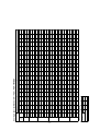
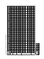
Cooling Capacity (Standard Air Flow) ; PEH-7MYB-EU
25.0
24.4
23.9
23.3
22.7
25.0
24.4
23.9
23.3
22.7
24.4
22.0
23.9
23.3
22.7
22.0
21.2
23.3
22.7
22.0
21.2
20.7
20.1
22.0
21.2
20.7
20.1
19.6
20.7
20.1
19.6
kW
Q
14. 0
15. 2
16. 5
17. 5
18. 7
12. 0
13. 2
14. 3
15. 4
16. 8
10. 8
18. 0
12. 2
13. 3
14. 6
15. 6
16. 8
11. 2
12. 5
13. 6
14. 7
16. 1
17. 3
11. 7
12. 7
13. 9
15. 3
16. 4
11. 6
12. 9
14. 1
kW
SHC
5.0
0 .5 6
0 .6 2
0 .6 9
0 .7 5
0 .8 2
0 .4 8
0 .5 4
0 .6 0
0 .6 6
0 .7 4
0 .4 4
0 .8 2
0 .5 1
0 .5 7
0 .6 4
0 .7 1
0 .7 9
0 .4 8
0 .5 5
0 .6 2
0 .6 9
0 .7 8
0 .8 6
0 .5 3
0 .6 0
0 .6 7
0 .7 6
0 .8 4
0 .5 6
0 .6 4
0 .7 2
SHF
6 .0
5 .9
5 .8
5 .7
5 .5
6 .0
5 .9
5 .8
5 .7
5 .5
5 .9
5 .5
5 .8
5 .7
5 .5
5 .5
5 .4
5 .7
5 .5
5 .5
5 .4
5 .4
5 .3
5 .5
5 .4
5 .4
5 .3
5 .3
5 .4
5 .3
5 .3
kW
T/I
24.8
24.2
23.6
23.0
22.4
24.8
24.2
23.6
23.0
22.4
24. 2
21.6
23.6
23.0
22.4
21.6
20.9
23.0
22.4
21.6
20.9
20.3
19.7
21.6
20.9
20.3
19.7
19.2
20.3
19.7
19.2
kW
Q
10. 0
12. 9
14. 3
15. 3
16. 5
17. 7
10. 9
12. 1
13. 4
14. 5
15. 7
9 .9
16. 9
11. 3
12. 4
13. 6
14. 7
15. 9
10. 1
11. 4
12. 5
13. 8
15. 0
16. 4
10. 6
11. 7
12. 8
14. 2
15. 3
10. 6
11. 8
13. 0
kW
SHC
0 .5 2
0 .5 9
0 .6 5
0 .7 2
0 .7 9
0 .4 4
0 .5 0
0 .5 7
0 .6 3
0 .7 0
0.41
0 .7 8
0 .4 8
0 .5 4
0 .6 1
0 .6 8
0 .7 6
0 .4 4
0 .5 1
0 .5 8
0 .6 6
0 .7 4
0 .8 3
0 .4 9
0 .5 6
0 .6 3
0 .7 2
0 .8 0
0 .5 2
0 .6 0
0 .6 8
SHF
6 .1
6 .0
5 .9
5 .8
5 .7
6 .1
6 .0
5 .9
5 .8
5 .7
6.0
5 .6
5 .9
5 .8
5 .7
5 .6
5 .5
5 .8
5 .7
5 .6
5 .5
5 .5
5 .4
5 .6
5 .5
5 .5
5 .4
5 .3
5 .5
5 .4
5 .3
kW
T/I
24. 6
24. 0
23. 3
22. 7
22. 0
24. 6
24. 0
23. 3
22. 7
22. 0
24. 0
21. 2
23. 3
22. 7
22. 0
21. 2
20. 5
22. 7
22. 0
21. 2
20. 5
19. 9
19. 4
2 1. 2
2 0. 5
19. 9
1 9. 4
1 8. 8
1 9. 9
19. 4
18. 8
kW
Q
15.0
1 2. 8
1 4. 1
1 5. 2
1 6. 5
1 7. 6
1 0. 8
1 2. 0
1 3. 3
1 4. 3
1 5. 6
10.1
1 6. 6
1 1. 2
1 2. 5
1 3. 4
1 4. 7
1 5. 8
1 0. 0
1 1. 2
1 2. 5
1 3. 5
1 4. 9
1 6. 3
1 0. 4
1 1. 5
1 2. 8
1 3. 9
1 5. 0
1 0. 4
1 1. 6
1 3. 0
kW
SHC
0 .5 2
0 .5 9
0 .6 5
0 .7 3
0 .8 0
0 .4 4
0 .5 0
0 .5 7
0 .6 3
0 .7 1
0.42
0 .7 8
0 .4 8
0 .5 5
0 .6 1
0 .6 9
0 .7 7
0 .4 4
0 .5 1
0 .5 9
0 .6 6
0 .7 5
0 .8 4
0 .4 9
0 .5 6
0 .6 4
0 .7 2
0 .8 0
0 .5 2
0 .6 0
0 .6 9
SHF
6 .2
6 .1
6 .0
5 .9
5 .8
6 .2
6 .1
6 .0
5 .9
5 .8
6. 1
5 .7
6 .0
5 .9
5 .8
5 .7
5 .6
5 .9
5 .8
5 .7
5 .6
5 .5
5 .5
5 .7
5 .6
5 .5
5 .5
5 .4
5 .5
5 .5
5 .4
kW
T/I
24.2
23.5
22.8
22.2
21.5
24.2
23.5
22.8
22.2
21.5
2 3. 5
20.8
22.8
22.2
21.5
20.8
20.0
22.2
21.5
20.8
20.0
19.5
18.9
20.8
20.0
19.5
18.9
18.3
19.5
18.9
18.3
kW
Q
20.0
12. 8
14. 1
15. 1
16. 4
17. 4
10. 6
12. 0
13. 0
14. 2
15. 5
9 .9
16. 6
11. 0
12. 2
13. 3
14. 5
15. 6
9. 8
11. 2
12. 3
13. 4
14. 8
16. 1
10. 2
11. 4
12. 5
13. 6
14. 7
10. 1
11. 5
12. 6
kW
SHC
0 .5 3
0 .6 0
0 .6 6
0 .7 4
0 .8 1
0 .4 4
0 .5 1
0 .5 7
0 .6 4
0 .7 2
0.42
0 .8 0
0 .4 8
0 .5 5
0 .6 2
0 .7 0
0 .7 8
0 .4 4
0 .5 2
0 .5 9
0 .6 7
0 .7 6
0 .8 5
0 .4 9
0 .5 7
0 .6 4
0 .7 2
0 .8 0
0 .5 2
0 .6 1
0 .6 9
SHF
T/I
6 .4
6 .3
6 .2
6 .1
6 .0
6 .4
6 .3
6 .2
6 .1
6 .0
6.3
6 .0
6 .2
6 .1
6 .0
6 .0
5 .9
6 .1
6 .0
6 .0
5 .9
5 .8
5 .8
6 .0
5 .9
5 .8
5 .8
5 .7
5 .8
5 .8
5 .7
kW
CAPACITY TABLES
- 11 -
21.1
21. 7
19.6
20.3
21.1
21.7
22.4
23. 0
20.3
21.1
21.7
22.4
23.0
23.7
21.1
21.7
20
21
18
19
20
21
22
23
19
20
21
22
23
24
20
21
23.7
20.3
19
24
19.6
18
23.0
19.0
17
23
18.4
16
22.4
20. 3
19
22
19.6
18
18.4
16
19.0
17.9
15
17
19.0
17
12. 8
14. 0
15. 0
16. 3
17. 3
10. 4
11. 7
13. 0
14. 1
15. 6
9 .4
16. 6
10. 7
11. 9
13. 1
14. 2
15. 4
9 .6
10. 9
12. 2
13. 3
14. 6
15. 8
9 .9
11. 1
12. 3
13. 4
14. 5
10. 1
11. 2
12. 5
kW
60
1.0
1.0
0.989
1,000
0.975
L/S
inpu t
50
833
CMM
0 .5 4
0 .6 1
0 .6 7
0 .7 5
0 .8 2
0 .4 4
0 .5 1
0 .5 8
0 .6 5
0 .7 4
0.41
0 .8 2
0 .4 8
0 .5 5
0 .6 2
0 .7 0
0 .7 9
0.44
0 .5 2
0 .6 0
0 .6 8
0 .7 7
0 .8 6
0.49
0 .5 7
0 .6 5
0 .7 3
0 .8 1
0 .5 3
0 .6 1
0 .7 0
SHF
capacity
Air volume
25.0
SHC
Factor for various air flow(Cooling)
30
28
26
24
22
18.4
17.9
15
16
WB°C
DB°C
20
kW
Indoor
Indoor
Q
Outdoor DB°C
1.009
1.024
1,167
70
6 .6
6 .6
6 .5
6 .4
6 .3
6 .6
6 .6
6 .5
6 .4
6 .3
6.6
6 .3
6 .5
6 .4
6 .3
6 .3
6 .2
6.4
6 .3
6 .3
6 .2
6 .1
6 .0
6.3
6 .2
6 .1
6 .0
6 .0
6 .1
6 .0
6 .0
kW
T/ I
23.1
22.4
21.7
21.0
20.3
23.1
22.4
21.7
21.0
20.3
22. 4
19.6
21.7
21.0
20.3
19.6
18.8
21. 0
20.3
19.6
18.8
18.2
17.7
19. 6
18.8
18.2
17.7
17.2
18. 2
17.7
17.2
kW
Q
12. 7
13. 9
15. 0
16. 0
17. 1
10. 4
11. 7
12. 8
14. 1
15. 2
9 .4
16. 4
10. 6
11. 8
12. 8
14. 1
15. 0
9 .5
10. 8
11. 9
13. 0
14. 2
15. 6
9 .6
10. 9
12. 0
13. 1
14. 1
9 .7
11. 0
12. 0
kW
SHC
30.0
0 .5 5
0 .6 2
0 .6 9
0 .7 6
0 .8 4
0 .4 5
0 .5 2
0 .5 9
0 .6 7
0 .7 5
0.42
0 .8 4
0 .4 9
0 .5 6
0 .6 3
0 .7 2
0 .8 0
0.45
0 .5 3
0 .6 1
0 .6 9
0 .7 8
0 .8 8
0.49
0 .5 8
0 .6 6
0 .7 4
0 .8 2
0.53
0 .6 2
0 .7 0
SHF
7 .1
7 .0
6 .9
6 .9
6 .8
7 .1
7 .0
6 .9
6 .9
6 .8
7. 0
6 .7
6 .9
6 .9
6 .8
6 .7
6 .6
6. 9
6 .8
6 .7
6 .6
6 .6
6 .5
6. 7
6 .6
6 .6
6 .5
6 .4
6. 6
6 .5
6 .4
kW
T/ I
Cooling Capacity (Standard Air Flow) ; PEH-7MYB-EU
22.6
21.8
21.1
20.3
19.6
22.6
21.8
21.1
20.3
19.6
2 1. 8
18.8
21.1
20.3
19.6
18.8
18.0
2 0. 3
19.6
18.8
18.0
17.5
16.9
1 8. 8
18.0
17 .5
16.9
16.5
1 7. 5
16 .9
16.5
kW
Q
35.0
12 .6
13 .7
14 .7
15 .8
16 .8
10 .4
11 .6
12 .8
13 .8
15 .1
9 .4
16. 2
10 .5
11 .6
12 .7
13 .7
14 .8
9 .3
10 .6
11 .7
12 .6
14 .0
15 .1
9 .4
10. 5
11. 7
12. 7
13. 9
9 .4
10. 5
11 .7
kW
SHC
0.56
0.63
0.70
0.78
0.86
0.46
0.53
0.61
0.68
0.77
0. 4 3
0.86
0.50
0.57
0.65
0.73
0.82
0. 46
0.54
0.62
0.70
0.80
0.89
0 .5 0
0 .5 8
0 .6 7
0 .7 5
0 .8 4
0.54
0 .6 2
0.71
SHF
7. 5
7. 5
7. 4
7.4
7.3
7. 5
7. 5
7. 4
7.4
7.3
7 .5
7.2
7. 4
7.4
7.3
7.2
7.1
7.4
7.3
7.2
7.1
7.0
6.9
7 .2
7 .1
7 .0
6 .9
6 .8
7.0
6 .9
6.8
kW
T/ I
2 1.7
2 1.0
2 0.2
19.5
18.7
2 1.7
2 1.0
2 0.2
19.5
18.7
21.0
18.0
2 0.2
19.5
18.7
18.0
17.2
19. 5
18.7
18.0
17.2
16.6
16.0
18. 0
17.2
16.6
16.0
15.5
16. 6
16.0
15.5
kW
Q
40. 0
12. 6
13. 6
14. 6
15. 8
16. 6
10. 2
11. 5
12. 5
13. 4
14. 8
9. 0
15. 8
10. 1
11. 3
12. 3
13. 5
14. 4
9 .0
10. 3
11. 3
12. 4
13. 6
14. 7
9 .2
10. 1
11. 3
12. 3
13. 5
9 .0
10. 1
11. 3
kW
SHC
0 .5 8
0 .6 5
0 .7 2
0 .8 1
0 .8 9
0 .4 7
0 .5 5
0 .6 2
0 .6 9
0 .7 9
0 .4 3
0 .8 8
0 .5 0
0 .5 8
0 .6 6
0 .7 5
0 .8 4
0.46
0 .5 5
0 .6 3
0 .7 2
0 .8 2
0 .9 2
0.51
0 .5 9
0 .6 8
0 .7 7
0 .8 7
0.54
0 .6 3
0 .7 3
SHF
8 .1
8 .1
8 .0
7 .9
7 .8
8 .1
8 .1
8 .0
7 .9
7 .8
8 .1
7 .7
8 .0
7 .9
7 .8
7 .7
7 .6
7.9
7 .8
7 .7
7 .6
7 .6
7 .5
7.7
7 .6
7 .6
7 .5
7 .4
7.6
7 .5
7 .4
kW
T/ I
20.7
19.9
19.2
18.4
17.7
20.7
19.9
19.2
18.4
17.7
19. 9
16.9
19. 2
18.4
17.7
16.9
16.2
18. 4
17. 7
16.9
16.2
15.5
14.9
16. 9
16. 2
15.5
14.9
14.2
15. 5
14. 9
14.2
kW
Q
12. 2
13. 2
14. 2
15. 3
16. 4
10. 1
11. 2
12. 1
13. 1
14. 3
8 .4
15. 4
9 .8
10. 9
12. 0
13. 0
13. 9
8 .7
9 .9
11. 0
11. 8
13. 0
14. 0
8 .8
9 .7
10. 7
11. 7
12. 6
8 .4
9 .5
10. 5
kW
SHC
46.0
0 .5 9
0 .6 6
0 .7 4
0 .8 3
0 .9 3
0 .4 9
0 .5 6
0 .6 3
0 .7 1
0 .8 1
0.42
0 .9 1
0.51
0 .5 9
0 .6 8
0 .7 7
0 .8 6
0.47
0.56
0 .6 5
0 .7 3
0 .8 4
0 .9 4
0.52
0.60
0 .6 9
0 .7 9
0 .8 9
0.54
0.64
0 .7 4
SHF
T/ I
8 .9
8 .7
8 .6
8 .5
8 .4
8 .9
8 .7
8 .6
8 .5
8 .4
8. 7
8 .4
8. 6
8 .5
8 .4
8 .4
8 .3
8. 5
8. 4
8 .4
8 .3
8 .2
8 .1
8. 4
8. 3
8 .2
8 .1
8 .1
8. 2
8. 1
8 .1
kW
- 12 -
Q
kW
13.3
13.1
12.9
12.8
12.6
12.5
12.3
12.2
12.1
12.0
11.9
11.7
11.6
Indoor
DB°C
15
16
17
18
19
20
21
22
23
24
25
26
27
-15. 0
kW
T/I
5.2
5.1
5.0
4.9
4.8
4.7
4.6
4.5
4.4
4.4
4.3
4.2
4.1
Outdoor WB°C
- 10. 0
12. 5
12. 7
12. 9
13. 1
13. 3
13. 5
13. 7
13. 9
14. 0
14. 2
14. 4
14. 5
14. 7
kW
Q
5 .5
5 .5
5 .4
5 .3
5 .2
5 .1
5 .0
5 .0
4 .9
4 .8
4 .8
4 .7
4 .6
kW
T/I
14. 3
14. 5
14. 7
14. 9
15. 1
15. 3
15. 5
15. 7
15. 9
16. 0
16. 2
16. 4
16. 6
kW
Q
- 5. 0
6 .2
6 .1
6 .0
5 .9
5 .8
5 .7
5 .6
5 .5
5 .5
5 .4
5 .3
5 .2
5 .2
kW
T/I
16. 1
16. 3
16. 5
16. 7
16. 9
17. 1
17. 3
17. 5
17. 7
17. 9
18. 1
18. 3
18. 5
kW
Q
0 .0
6 .8
6 .7
6 .6
6 .5
6 .4
6 .3
6 .2
6 .1
6 .0
6 .0
5 .9
5 .8
5 .7
kW
T/I
18. 6
18. 7
18. 9
19. 1
19. 2
19. 4
19. 5
19. 7
19. 9
20.1
20.3
20.5
20.7
kW
Q
5.0
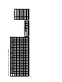
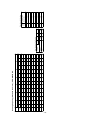
Heating Capacity (Standard Air Flow) ; PEH-7MYB-EU
7 .5
7 .4
7 .2
7 .1
7 .0
6 .9
6 .8
6 .7
6 .6
6.5
6.4
6.3
6.3
kW
T/I
21. 1
21. 2
21. 3
21. 4
21. 5
21. 7
21. 8
21. 9
22. 1
22. 3
22. 5
22. 7
22. 9
kW
Q
10.0
8 .1
8 .0
7 .9
7 .8
7 .6
7 .5
7 .4
7 .3
7 .2
7 .1
7 .0
6 .9
6 .8
kW
T/I
23. 3
23. 5
23. 7
23. 9
24. 1
24. 3
24. 5
24. 7
24. 9
25. 1
25. 3
25. 5
25. 7
kW
Q
15. 0
T/I
8 .6
8 .4
8 .3
8 .2
8 .0
7 .9
7 .8
7 .6
7 .5
7 .4
7 .3
7 .2
7 .1
kW
1.0
1.0
1.028
inpu t
1,000
0.980
833
L/S
60
capacity
Air volume
50
CMM
Factor for various air flow(Cooling)
0.980
1.011
1,167
70
0.89
-4
-15
-12
-10
0.92
0.92
0.92
0.92
0.86
-2
0.92
0.85
0
-8
0.88
2
-6
1.0
0.98
4
reduction ratio
WB°C
6
Heating capacity
outdoor
Reduction ratio by frosting
- 13 -
26. 8
27. 5
25. 1
26. 0
26. 8
27. 5
28. 2
28. 8
26.0
26. 8
27. 5
28. 2
28. 8
29. 5
26.8
27.5
20
21
18
19
20
21
22
23
19
20
21
22
23
24
20
21
29. 5
26. 0
24
25. 1
18
19
28. 8
24. 4
17
23
23.8
16
28. 2
26. 0
19
22
25. 1
18
23. 8
16
24. 4
23. 1
15
17
24. 4
17
1 6. 2
1 7. 9
1 9. 1
20. 6
22. 0
1 3. 9
1 5. 3
1 6. 9
1 8. 2
1 9. 6
20. 8
1 2. 7
1 4. 1
1 5. 7
1 6. 9
1 8. 4
1 9. 6
1 2. 7
1 4. 2
1 5. 6
1 6. 8
1 8. 6
20. 2
1 3. 2
1 4. 5
1 5. 6
1 7. 1
1 8. 5
1 2. 9
1 4. 5
1 5. 9
kW
SHC
70
1.0
1.0
0.991
1,167
0.976
L/S
0 .5 5
0 .6 2
0 .6 8
0 .7 5
0 .8 2
0 .4 7
0 .5 3
0 .6 0
0 .6 6
0 .7 3
0 .8 0
0 .4 4
0 .5 0
0 .5 7
0 .6 3
0 .7 1
0 .7 8
0 .4 6
0 .5 3
0 .6 0
0 .6 7
0 .7 6
0 .8 5
0 .5 1
0 .5 8
0 .6 4
0 .7 2
0 .8 0
0 .5 3
0 .6 1
0 .6 9
SHF
inpu t
60
1,000
CMM
-5.0
capacity
Air volume
Factor for various air flow(Cooling)
30
28
26
24
22
23. 8
23. 1
15
16
WB°C
DB°C
20
kW
Indoor
Indoor
Q
Outdoor DB°C
1.009
1.025
1,333
80
7 .3
7 .1
7 .0
6 .8
6 .7
7 .3
7 .1
7 .0
6 .8
6 .7
6 .6
7 .1
7 .0
6 .8
6 .7
6 .6
6 .5
6 .8
6 .7
6 .6
6 .5
6 .4
6 .4
6 .6
6 .5
6 .4
6 .4
6 .4
6 .4
6 .4
6 .4
kW
T/I
29.4
28.7
28.1
27.4
26.7
29.4
28.7
28.1
27.4
26.7
25.9
28.7
28.1
27.4
26.7
25.9
25.0
27.4
26.7
25.9
25.0
24.3
23.7
25.9
25.0
24.3
23.7
23.0
24.3
23.7
23.0
kW
Q
16. 2
17. 8
19. 1
20. 8
22. 2
13. 8
15. 2
16. 8
18. 4
19. 5
20. 7
12. 3
14. 0
15. 6
16. 8
18. 1
19. 2
12. 3
14. 2
15. 5
17. 0
18. 5
20. 1
13. 2
14. 5
15. 8
17. 0
18. 4
12. 9
14. 4
15. 9
kW
SHC
0. 0
0 .5 5
0 .6 2
0 .6 8
0 .7 6
0 .8 3
0 .4 7
0 .5 3
0 .6 0
0 .6 7
0 .7 3
0 .8 0
0 .4 3
0 .5 0
0 .5 7
0 .6 3
0 .7 0
0 .7 7
0 .4 5
0 .5 3
0 .6 0
0 .6 8
0 .7 6
0 .8 5
0 .5 1
0 .5 8
0 .6 5
0 .7 2
0 .8 0
0 .5 3
0 .6 1
0 .6 9
SHF
7 .2
7 .1
6 .9
6 .8
6 .6
7 .2
7 .1
6 .9
6 .8
6 .6
6 .5
7 .1
6 .9
6 .8
6 .6
6 .5
6 .5
6 .8
6 .6
6 .5
6 .5
6 .4
6 .4
6 .5
6 .5
6 .4
6 .4
6 .3
6 .4
6 .4
6 .3
kW
T/I
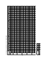
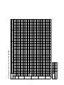
Cooling Capacity (Standard Air Flow) ; PEH-8MYB-EU
29.3
28.6
27.9
27.3
26.6
29.3
28.6
27.9
27.3
26.6
25.7
28.6
27.9
27.3
26.6
25.7
24.9
27.3
26.6
25.7
24.9
24.2
23.5
25.7
24.9
24.2
23.5
22.9
24.2
23.5
22.9
kW
Q
16. 1
17. 7
19. 0
20. 7
22. 1
13. 5
15. 2
16. 8
18. 3
19. 7
20. 6
12. 0
13. 7
15. 3
16. 8
17. 8
18. 6
12. 0
13. 8
15. 4
16. 9
18. 4
19. 8
13. 1
14. 4
15. 7
17. 2
18. 3
12. 8
14. 4
15. 6
kW
SHC
5.0
0 .5 5
0 .6 2
0 .6 8
0 .7 6
0 .8 3
0 .4 6
0 .5 3
0 .6 0
0 .6 7
0 .7 4
0 .8 0
0 .4 2
0 .4 9
0 .5 6
0 .6 3
0 .6 9
0 .7 5
0 .4 4
0 .5 2
0 .6 0
0 .6 8
0 .7 6
0 .8 4
0 .5 1
0 .5 8
0 .6 5
0 .7 3
0 .8 0
0 .5 3
0 .6 1
0 .6 8
SHF
7 .1
7 .0
6 .9
6 .7
6 .6
7 .1
7 .0
6 .9
6 .7
6 .6
6 .5
7 .0
6 .9
6 .7
6 .6
6 .5
6 .4
6 .7
6 .6
6 .5
6 .4
6 .4
6 .4
6 .5
6 .4
6 .4
6 .4
6 .3
6 .4
6 .4
6 .3
kW
T/I
29.0
28.3
27.6
26.9
26.2
29.0
28.3
27.6
26.9
26.2
25.3
28.3
27.6
26.9
26.2
25.3
24.4
26.9
26.2
25.3
24.4
23.8
23.1
25.3
24.4
23.8
23.1
22.4
23.8
23.1
22.4
kW
Q
10. 0
16. 0
17. 6
19. 1
20. 4
22. 0
13. 4
15. 0
16. 6
18. 0
19. 4
20. 5
11. 9
13. 5
15. 1
16. 5
17. 7
18. 8
12. 4
13. 9
15. 4
16. 8
18. 3
19. 6
12. 9
14. 2
15. 2
16. 6
18. 2
12. 8
14. 1
15. 5
kW
SHC
0 .5 5
0 .6 2
0 .6 9
0 .7 6
0 .8 4
0 .4 6
0 .5 3
0 .6 0
0 .6 7
0 .7 4
0 .8 1
0 .4 2
0 .4 9
0 .5 6
0 .6 3
0 .7 0
0 .7 7
0 .4 6
0 .5 3
0 .6 1
0 .6 9
0 .7 7
0 .8 5
0 .5 1
0 .5 8
0 .6 4
0 .7 2
0 .8 1
0 .5 4
0 .6 1
0 .6 9
SHF
7 .3
7 .1
7 .0
6 .9
6 .7
7 .3
7 .1
7 .0
6 .9
6 .7
6 .7
7 .1
7 .0
6 .9
6 .7
6 .7
6 .6
6 .9
6 .7
6 .7
6 .6
6 .5
6 .4
6 .7
6 .6
6 .5
6 .4
6 .4
6 .5
6 .4
6 .4
kW
T/I
28. 8
28. 1
27. 3
26. 5
25. 7
28. 8
28. 1
27. 3
26. 5
25. 7
24. 9
28. 1
27. 3
26. 5
25. 7
24. 9
24. 0
26. 5
25. 7
24. 9
24. 0
23. 3
22. 7
2 4. 9
2 4. 0
23. 3
2 2. 7
2 2. 0
2 3. 3
22. 7
22. 0
kW
Q
15.0
1 5. 9
1 7. 4
1 8. 8
20. 4
21. 6
1 3. 3
1 4. 9
1 6. 4
1 7. 8
1 9. 0
20. 1
1 1. 8
1 3. 4
1 4. 8
1 6. 2
1 7. 7
1 8. 9
1 2. 5
1 3. 9
1 5. 4
1 6. 5
1 8. 0
1 9. 3
1 2. 7
1 3. 7
1 4. 7
1 6. 3
1 7. 8
1 2. 6
1 4. 0
1 5. 2
kW
SHC
0 .5 5
0 .6 2
0 .6 9
0 .7 7
0 .8 4
0 .4 6
0 .5 3
0 .6 0
0 .6 7
0 .7 4
0 .8 1
0 .4 2
0 .4 9
0 .5 6
0 .6 3
0 .7 1
0 .7 9
0 .4 7
0 .5 4
0 .6 2
0 .6 9
0 .7 7
0 .8 5
0 .5 1
0 .5 7
0 .6 3
0 .7 2
0 .8 1
0 .5 4
0 .6 2
0 .6 9
SHF
7 .4
7 .3
7 .1
7 .0
6 .9
7 .4
7 .3
7 .1
7 .0
6 .9
6 .8
7 .3
7 .1
7 .0
6 .9
6 .8
6 .7
7 .0
6 .9
6 .8
6 .7
6 .6
6 .5
6 .8
6 .7
6 .6
6 .5
6 .4
6 .6
6 .5
6 .4
kW
T/I
28.3
27.5
26.7
26.0
25.2
28.3
27.5
26.7
26.0
25.2
24.3
27.5
26.7
26.0
25.2
24.3
23.4
26.0
25.2
24.3
23.4
22.8
22.1
24.3
23.4
22.8
22.1
21.5
22.8
22.1
21.5
kW
Q
20.0
15. 8
17. 3
18. 7
20. 2
21. 7
13. 3
14. 9
16. 3
17. 7
18. 9
19. 9
11. 8
13. 4
14. 8
16. 1
17. 5
18. 7
11. 9
13. 6
15. 1
16. 4
17. 8
19. 0
12. 4
13. 6
14. 8
16. 1
17. 6
12. 5
13. 7
15. 0
kW
SHC
0 .5 6
0 .6 3
0 .7 0
0 .7 8
0 .8 6
0 .4 7
0 .5 4
0 .6 1
0 .6 8
0 .7 5
0 .8 2
0 .4 3
0 .5 0
0 .5 7
0 .6 4
0 .7 2
0 .8 0
0 .4 6
0 .5 4
0 .6 2
0 .7 0
0 .7 8
0 .8 6
0 .5 1
0 .5 8
0 .6 5
0 .7 3
0 .8 2
0 .5 5
0 .6 2
0 .7 0
SHF
T/I
7 .6
7 .5
7 .4
7 .3
7 .2
7 .6
7 .5
7 .4
7 .3
7 .2
7 .1
7 .5
7 .4
7 .3
7 .2
7 .1
7 .0
7 .3
7 .2
7 .1
7 .0
7 .0
6 .9
7 .1
7 .0
7 .0
6 .9
6 .8
7 .0
6 .9
6 .8
kW
- 14 -
24.6
25.4
22.9
23.8
24.6
25.4
26.2
27.0
23.8
24.6
25.4
26.2
27.0
27.7
24.6
25.4
20
21
18
19
20
21
22
23
19
20
21
22
23
24
20
21
27.7
23.8
19
24
22.9
18
27.0
22.2
17
23
21.6
16
26.2
23.8
19
22
22.9
18
21.6
16
22.2
20.9
15
17
22.2
17
15. 8
17. 2
18. 3
20. 1
21. 4
13. 0
14. 6
16. 0
17. 3
18. 7
19. 7
11. 6
13. 1
14. 7
16. 0
17. 3
18. 3
11. 7
13. 3
14. 7
16. 0
17. 6
18. 8
12. 1
13. 5
14. 7
16. 2
17. 3
12. 2
13. 6
14. 8
kW
70
1.0
1.0
0.991
1,167
0.976
L/S
inpu t
60
1,000
CMM
0 .5 7
0 .6 4
0 .7 0
0 .7 9
0 .8 7
0 .4 7
0 .5 4
0 .6 1
0 .6 8
0 .7 6
0 .8 3
0 .4 3
0 .5 0
0 .5 8
0 .6 5
0 .7 3
0 .8 0
0 .4 6
0 .5 4
0 .6 2
0 .7 0
0 .7 9
0 .8 7
0 .5 1
0 .5 9
0 .6 6
0 .7 5
0 .8 3
0 .5 5
0 .6 3
0 .7 1
SHF
capacity
Air volume
25.0
SHC
Factor for various air flow(Cooling)
30
28
26
24
22
21.6
20.9
15
16
WB°C
DB°C
20
kW
Indoor
Indoor
Q
Outdoor DB°C
1.009
1.025
1,333
80
7 .9
7 .8
7 .7
7 .6
7 .6
7 .9
7 .8
7 .7
7 .6
7 .6
7 .5
7 .8
7 .7
7 .6
7 .6
7 .5
7 .4
7 .6
7 .6
7 .5
7 .4
7 .3
7 .2
7 .5
7 .4
7 .3
7 .2
7 .1
7 .3
7 .2
7 .1
kW
T/ I
27.1
26.2
25.4
24.6
23. 8
27.1
26.2
25.4
24.6
23.8
22.9
26.2
25.4
24.6
23.8
22.9
22.0
24.6
23.8
22.9
22.0
21.3
20.7
22.9
22.0
21.3
20.7
20.1
21.3
20.7
20.1
kW
Q
16. 0
17. 1
18. 3
19. 7
2 1. 1
13. 0
14. 4
15. 8
17. 0
18. 3
19. 2
11. 3
13. 0
14. 3
15. 7
16. 9
18. 0
11. 3
13. 1
14. 4
15. 6
17. 1
18. 4
11. 9
13. 0
14. 3
15. 7
17. 1
11. 7
13. 0
14. 5
kW
SHC
30.0
0 .5 9
0 .6 5
0 .7 2
0 .8 0
0 .8 9
0 .4 8
0 .5 5
0 .6 2
0 .6 9
0 .7 7
0 .8 4
0 .4 3
0 .5 1
0 .5 8
0 .6 6
0 .7 4
0 .8 2
0 .4 6
0 .5 5
0 .6 3
0 .7 1
0 .8 0
0 .8 9
0 .5 2
0 .5 9
0 .6 7
0 .7 6
0 .8 5
0 .5 5
0 .6 3
0 .7 2
SHF
8 .4
8 .4
8 .3
8 .2
8 .2
8 .4
8 .4
8 .3
8 .2
8 .2
8 .0
8 .4
8 .3
8 .2
8 .2
8 .0
7 .9
8 .2
8 .2
8 .0
7 .9
7 .8
7 .7
8 .0
7 .9
7 .8
7 .7
7 .6
7 .8
7 .7
7 .6
kW
T/ I
Cooling Capacity (Standard Air Flow) ; PEH-8MYB-EU
26.4
25.5
24.6
23.8
22.9
26.4
25.5
24.6
23.8
22.9
22.0
25.5
24.6
23.8
22.9
22.0
21.1
23.8
22.9
22.0
21.1
20.5
19.8
22.0
21.1
20 .5
19.8
19.4
20.5
19 .8
19.4
kW
Q
35.0
16 .1
17 .1
18 .0
19 .5
20 .6
12 .7
14 .0
15 .5
16 .6
17 .8
18. 7
11 .0
12 .6
14 .0
15 .3
16 .5
17 .5
11 .2
12 .6
14 .1
15 .2
16 .6
17 .8
11. 4
12. 7
13. 7
15. 2
16. 8
11. 0
12. 5
14 .1
kW
SHC
0.61
0.67
0.73
0.82
0.90
0.48
0.55
0.63
0.70
0.78
0.85
0.43
0.51
0.59
0.67
0.75
0.83
0.47
0.55
0.64
0.72
0.81
0.90
0 .5 2
0 .6 0
0 .6 7
0 .7 7
0 .8 7
0 .5 4
0 .6 3
0.73
SHF
8. 9
8. 9
8. 8
8. 8
8. 8
8. 9
8. 9
8. 8
8. 8
8. 8
8.6
8. 9
8. 8
8. 8
8. 8
8. 6
8. 4
8. 8
8. 8
8. 6
8. 4
8.3
8.2
8 .6
8 .4
8 .3
8 .2
8 .2
8 .3
8 .2
8.2
kW
T/ I
2 5.4
2 4.5
2 3.7
2 2.8
2 1.9
2 5.4
2 4.5
2 3.7
2 2.8
2 1.9
21.0
2 4.5
2 3.7
2 2.8
2 1.9
2 1.0
2 0.1
2 2.8
2 1.9
2 1.0
2 0.1
19.4
18.7
21.0
20.1
19.4
18.7
18.1
19.4
18.7
18.1
kW
Q
40. 0
16. 0
16. 9
17. 7
18. 9
20. 1
12. 2
13. 7
15. 1
16. 6
17. 5
18. 5
10. 5
12. 3
13. 7
15. 1
16. 2
17. 1
10. 7
12. 3
13. 7
14. 9
16. 1
17. 2
11. 1
12. 3
13. 2
14. 6
15. 9
10. 7
12. 2
13. 4
kW
SHC
0 .6 3
0 .6 9
0 .7 5
0 .8 3
0 .9 2
0 .4 8
0 .5 6
0 .6 4
0 .7 3
0 .8 0
0 .8 8
0 .4 3
0 .5 2
0 .6 0
0 .6 9
0 .7 7
0 .8 5
0 .4 7
0 .5 6
0 .6 5
0 .7 4
0 .8 3
0 .9 2
0 .5 3
0 .6 1
0 .6 8
0 .7 8
0 .8 8
0 .5 5
0 .6 5
0 .7 4
SHF
9 .7
9 .6
9 .5
9 .4
9 .4
9 .7
9 .6
9 .5
9 .4
9 .4
9 .2
9 .6
9 .5
9 .4
9 .4
9 .2
9 .1
9 .4
9 .4
9 .2
9 .1
9 .0
8 .9
9 .2
9 .1
9 .0
8 .9
8 .8
9 .0
8 .9
8 .8
kW
T/ I
24.2
23.3
22.4
21.6
20.7
24.2
23.3
22.4
21.6
20.7
19.8
23.3
22.4
21.6
20.7
19.8
18.9
21.6
20.7
19.8
18.9
18.2
17.4
19.8
18.9
18.2
17.4
16.6
18.2
17.4
16.6
kW
Q
46. 0
15. 7
16. 6
17. 3
18. 3
19. 2
11. 6
13. 3
14. 8
16. 2
17. 2
18. 0
10. 0
11. 7
13. 2
14. 5
15. 4
16. 3
10. 3
11. 8
13. 1
14. 2
15. 2
16. 3
10. 7
11. 7
12. 7
13. 7
14. 8
10. 3
11. 5
12. 5
kW
SHC
0 .6 5
0 .7 1
0 .7 7
0 .8 5
0 .9 3
0 .4 8
0 .5 7
0 .6 6
0 .7 5
0 .8 3
0 .9 1
0 .4 3
0 .5 2
0 .6 1
0 .7 0
0 .7 8
0 .8 6
0 .4 8
0 .5 7
0 .6 6
0 .7 5
0 .8 4
0 .9 4
0 .5 4
0 .6 2
0 .7 0
0 .7 9
0 .8 9
0 .5 7
0 .6 6
0 .7 5
SHF
T/ I
1 0. 6
1 0. 4
1 0. 3
1 0. 2
1 0. 1
1 0. 6
1 0. 4
1 0. 3
1 0. 2
1 0. 1
1 0. 0
1 0. 4
1 0. 3
1 0. 2
1 0. 1
1 0. 0
9 .9
1 0. 2
1 0. 1
1 0. 0
9 .9
9 .8
9 .7
1 0. 0
9 .9
9 .8
9 .7
9 .6
9 .8
9 .7
9 .6
kW
- 15 -
Q
kW
14.5
14.3
14.2
14.0
13.8
13.6
13.5
13.4
13.2
13.1
13.0
12.8
12.7
Indoor
DB°C
15
16
17
18
19
20
21
22
23
24
25
26
27
-15. 0
T/I
5.5
5.4
5.2
5.1
5.0
4.9
4.8
4.7
4.6
4.5
4.5
4.4
4.3
kW
Outdoor WB°C
- 10. 0
13. 6
13. 9
14. 1
14. 3
14. 5
14. 7
15. 0
15. 2
15. 4
15. 5
15. 7
15. 9
16. 1
kW
Q
5 .8
5 .7
5 .6
5 .5
5 .4
5 .3
5 .3
5 .2
5 .1
5 .0
5 .0
4 .9
4 .8
kW
T/I
15. 6
15. 8
16. 1
16. 3
16. 5
16. 7
16. 9
17. 2
17. 4
17. 6
17. 8
18. 0
18. 2
kW
Q
- 5. 0
6 .4
6 .3
6 .2
6 .1
6 .1
6 .0
5 .9
5 .8
5 .7
5 .6
5 .5
5 .5
5 .4
kW
T/I
17. 6
17. 8
18. 0
18. 3
18. 5
18. 7
18. 9
19. 1
19. 4
19. 6
19. 8
20. 0
20. 2
kW
Q
0 .0
7 .1
7 .0
6 .9
6 .8
6 .7
6 .6
6 .5
6 .4
6 .3
6 .2
6 .1
6 .0
6 .0
kW
T/I
20.3
20.5
20.7
20.9
21.0
21.2
21.4
21.5
21.8
22.0
22.2
22.4
22.7
kW
Q
5.0
Heating Capacity (Standard Air Flow) ; PEH-8MYB-EU
7.8
7.7
7.6
7.4
7.3
7.2
7.1
7.0
6.9
6.8
6.7
6.6
6.5
kW
T/I
23. 1
23. 2
23. 3
23. 5
23. 6
23. 7
23. 8
24. 0
24. 2
24. 4
24. 6
24. 9
25. 1
kW
Q
10.0
8 .5
8 .4
8 .2
8 .1
8 .0
7 .8
7 .7
7 .6
7 .5
7 .4
7 .3
7 .2
7 .1
kW
T/I
25. 5
25. 7
26. 0
26. 2
26. 4
26. 6
26. 8
27. 1
27. 3
27. 5
27. 7
27. 9
28. 2
kW
Q
15. 0
T/I
8 .9
8 .8
8 .6
8 .5
8 .4
8 .2
8 .1
7 .9
7 .8
7 .7
7 .6
7 .5
7 .4
kW
inpu t
capacity
Air volume
1.0
1.010
1,167
1.0
1,000
L/S
70
0.989
60
CMM
Factor for various air flow(Cooling)
0.987
1.011
1,333
80
-15
-12
-10
-8
-6
-4
-2
0
2
4
6
WB°C
outdoor
0.92
0.92
0.92
0.92
0.92
0.89
0.86
0.85
0.88
0.98
1.0
reduction ratio
Heating capacit y
Reduction ratio by frosting
- 16 -
35. 1
36. 0
32.8
34.0
35.1
36.0
36. 9
37. 7
34.0
35.1
36.0
36.9
37.7
38. 6
35.1
36.0
20
21
18
19
20
21
22
23
19
20
21
22
23
24
20
21
38.6
34.0
19
24
32.8
18
37.7
32.0
17
23
31.1
16
36.9
34. 0
19
22
32. 8
18
31.1
16
32.0
30.2
15
17
32. 0
17
21. 2
23. 0
24. 7
26. 3
27. 8
1 8. 1
20. 0
21. 4
23. 0
24. 9
26. 8
1 6. 6
1 8. 4
20. 2
21. 8
23. 4
25. 0
1 6. 6
1 8. 6
20. 4
22. 0
23. 7
25. 5
1 7. 3
1 8. 7
20. 5
22. 1
23. 9
1 7. 3
1 9. 0
20. 9
kW
SHC
90
1.0
1.0
0.991
1,500
0.977
L/S
0 .5 5
0 .6 1
0 .6 7
0 .7 3
0 .7 9
0 .4 7
0 .5 3
0 .5 8
0 .6 4
0 .7 1
0 .7 9
0 .4 4
0 .5 0
0 .5 6
0 .6 2
0 .6 9
0 .7 6
0 .4 6
0 .5 3
0 .6 0
0 .6 7
0 .7 4
0 .8 2
0 .5 1
0 .5 7
0 .6 4
0 .7 1
0 .7 9
0 .5 4
0 .6 1
0 .6 9
SHF
inpu t
80
1,333
CMM
-5.0
capacity
Air volume
Factor for various air flow(Cooling)
30
28
26
24
22
31. 1
30.2
15
16
kW
WB°C
DB°C
20
Q
Indoor
Indoor
Outdoor DB°C
1.005
1.035
1,666
100
9 .2
9 .0
8 .8
8 .7
8 .5
9 .2
9 .0
8 .8
8 .7
8 .5
8 .4
9 .0
8 .8
8 .7
8 .5
8 .4
8 .2
8 .7
8 .5
8 .4
8 .2
8 .2
8 .1
8 .4
8 .2
8 .2
8 .1
8 .1
8 .2
8 .1
8 .1
kW
T/I
38.4
37.6
36.7
35.9
35.0
38.4
37.6
36.7
35.9
35.0
33.8
37.6
36.7
35.9
35.0
33.8
32.7
35.9
35.0
33.8
32.7
31.8
31.0
33.8
32.7
31.8
31.0
30.1
31.8
31.0
30.1
kW
Q
21. 1
22. 9
24. 6
26. 2
27. 6
18. 1
19. 9
21. 7
22. 9
25. 2
26. 7
16. 5
18. 4
20. 1
21. 7
23. 3
24. 8
16. 5
18. 5
20. 3
21. 9
23. 9
25. 4
17. 3
19. 0
20. 4
22. 3
23. 8
17. 2
18. 9
20. 8
kW
SHC
0. 0
0 .5 5
0 .6 1
0 .6 7
0 .7 3
0 .7 9
0 .4 7
0 .5 3
0 .5 9
0 .6 4
0 .7 2
0 .7 9
0 .4 4
0 .5 0
0 .5 6
0 .6 2
0 .6 9
0 .7 6
0 .4 6
0 .5 3
0 .6 0
0 .6 7
0 .7 5
0 .8 2
0 .5 1
0 .5 8
0 .6 4
0 .7 2
0 .7 9
0 .5 4
0 .6 1
0 .6 9
SHF
9 .1
9 .0
8 .8
8 .6
8 .4
9 .1
9 .0
8 .8
8 .6
8 .4
8 .3
9 .0
8 .8
8 .6
8 .4
8 .3
8 .2
8 .6
8 .4
8 .3
8 .2
8 .2
8 .1
8 .3
8 .2
8 .2
8 .1
8 .0
8 .2
8 .1
8 .0
kW
T/I
Q
38.3
37.4
36.6
35.7
34.8
38.3
37.4
36.6
35.7
34.8
33.7
37.4
36.6
35.7
34.8
33.7
32.5
35.7
34.8
33.7
32.5
31.7
30.8
33.7
32.5
31.7
30.8
30.0
31.7
30.8
30.0
kW
Cooling Capacity (Standard Air Flow) ; PEH-10MYB-EU
21. 1
22. 8
24. 5
26. 1
27. 5
18. 0
19. 8
21. 6
23. 2
25. 1
26. 6
16. 5
18. 3
20. 0
21. 6
23. 3
24. 7
16. 4
18. 5
20. 2
21. 8
23. 8
25. 6
17. 2
18. 9
20. 6
22. 2
23. 7
17. 1
18. 8
20. 7
kW
SHC
5.0
0 .5 5
0 .6 1
0 .6 7
0 .7 3
0 .7 9
0 .4 7
0 .5 3
0 .5 9
0 .6 5
0 .7 2
0 .7 9
0 .4 4
0 .5 0
0 .5 6
0 .6 2
0 .6 9
0 .7 6
0 .4 6
0 .5 3
0 .6 0
0 .6 7
0 .7 5
0 .8 3
0 .5 1
0 .5 8
0 .6 5
0 .7 2
0 .7 9
0 .5 4
0 .6 1
0 .6 9
SHF
9 .1
8 .9
8 .7
8 .6
8 .4
9 .1
8 .9
8 .7
8 .6
8 .4
8 .3
8 .9
8 .7
8 .6
8 .4
8 .3
8 .2
8 .6
8 .4
8 .3
8 .2
8 .1
8 .1
8 .3
8 .2
8 .1
8 .1
8 .0
8 .1
8 .1
8 .0
kW
T/I
38.0
37.1
36.1
35.2
34.3
38.0
37.1
36.1
35.2
34.3
33.1
37.1
36.1
35.2
34.3
33.1
32.0
35.2
34.3
33.1
32.0
31.1
30.2
33.1
32.0
31.1
30.2
29.4
31.1
30.2
29.4
kW
Q
10. 0
20. 9
22. 6
24. 2
25. 7
27. 1
17. 9
19. 7
21. 3
22. 9
24. 7
26. 2
16. 3
18. 1
19. 7
21. 2
22. 9
24. 3
16. 2
18. 2
19. 9
21. 4
23. 3
25. 1
16. 9
18. 5
20. 2
21. 8
23. 5
16. 8
18. 7
20. 6
kW
SHC
0 .5 5
0 .6 1
0 .6 7
0 .7 3
0 .7 9
0 .4 7
0 .5 3
0 .5 9
0 .6 5
0 .7 2
0 .7 9
0 .4 4
0 .5 0
0 .5 6
0 .6 2
0 .6 9
0 .7 6
0 .4 6
0 .5 3
0 .6 0
0 .6 7
0 .7 5
0 .8 3
0 .5 1
0 .5 8
0 .6 5
0 .7 2
0 .8 0
0 .5 4
0 .6 2
0 .7 0
SHF
9 .2
9 .1
8 .9
8 .7
8 .6
9 .2
9 .1
8 .9
8 .7
8 .6
8 .5
9 .1
8 .9
8 .7
8 .6
8 .5
8 .4
8 .7
8 .6
8 .5
8 .4
8 .3
8 .2
8 .5
8 .4
8 .3
8 .2
8 .1
8 .3
8 .2
8 .1
kW
T/I
37. 7
36. 7
35. 7
34. 7
33. 7
37. 7
36. 7
35. 7
34. 7
33. 7
32. 5
36. 7
35. 7
34. 7
33. 7
32. 5
31. 4
34. 7
33. 7
32. 5
31. 4
30. 5
29. 7
3 2. 5
3 1. 4
30. 5
2 9.7
2 8.8
3 0. 5
29. 7
28. 8
kW
Q
15.0
21. 1
22. 8
24. 3
25. 7
27. 0
1 7. 7
1 9. 5
21. 1
22. 6
24. 3
26. 0
1 6. 2
1 7. 9
1 9. 4
20. 9
22. 5
24. 2
1 6. 3
1 8. 2
1 9. 9
21. 3
23. 2
24. 9
1 6. 6
1 8. 2
1 9. 8
21. 7
23. 0
1 6. 8
1 8. 7
20. 2
kW
SHC
0 .5 6
0 .6 2
0 .6 8
0 .7 4
0 .8 0
0 .4 7
0 .5 3
0 .5 9
0 .6 5
0 .7 2
0 .8 0
0 .4 4
0 .5 0
0 .5 6
0 .6 2
0 .6 9
0 .7 7
0 .4 7
0 .5 4
0 .6 1
0 .6 8
0 .7 6
0 .8 4
0 .5 1
0 .5 8
0 .6 5
0 .7 3
0 .8 0
0 .5 5
0 .6 3
0 .7 0
SHF
9 .4
9 .2
9 .1
8 .9
8 .7
9 .4
9 .2
9 .1
8 .9
8 .7
8 .6
9 .2
9 .1
8 .9
8 .7
8 .6
8 .5
8 .9
8 .7
8 .6
8 .5
8 .4
8 .3
8 .6
8 .5
8 .4
8 .3
8 .2
8 .4
8 .3
8 .2
kW
T/I
37.0
36.0
35.0
34.0
33.0
37.0
36.0
35.0
34.0
33.0
31.8
36.0
35.0
34.0
33.0
31.8
30.7
34.0
33.0
31.8
30.7
29.8
28.9
31.8
30.7
29.8
28.9
28.1
29.8
28.9
28.1
kW
Q
20.0
20. 7
22. 3
23. 8
25. 5
26. 7
17. 4
19. 1
21. 0
22. 4
24. 1
25. 8
15. 8
17. 5
19. 4
20. 8
22. 3
23. 9
16. 0
17. 8
19. 4
20. 9
23. 0
24. 6
16. 2
18. 1
19. 7
21. 4
22. 7
16. 7
18. 2
19. 9
kW
SHC
0 .5 6
0 .6 2
0 .6 8
0 .7 5
0 .8 1
0 .4 7
0 .5 3
0 .6 0
0 .6 6
0 .7 3
0 .8 1
0 .4 4
0 .5 0
0 .5 7
0 .6 3
0 .7 0
0 .7 8
0 .4 7
0 .5 4
0 .6 1
0 .6 8
0 .7 7
0 .8 5
0 .5 1
0 .5 9
0 .6 6
0 .7 4
0 .8 1
0 .5 6
0 .6 3
0 .7 1
SHF
T/I
9 .7
9 .6
9 .4
9 .3
9 .2
9 .7
9 .6
9 .4
9 .3
9 .2
9 .1
9 .6
9 .4
9 .3
9 .2
9 .1
9 .0
9 .3
9 .2
9 .1
9 .0
8 .8
8 .7
9 .1
9 .0
8 .8
8 .7
8 .6
8 .8
8 .7
8 .6
kW
- 17 -
32.3
33.3
30.0
31.1
32.3
33.3
34.3
35.3
31.1
32.3
33.3
34.3
35.3
36.3
32.3
33.3
20
21
18
19
20
21
22
23
19
20
21
22
23
24
20
21
36.3
31.1
19
24
30.0
35.3
29.1
17
18
23
28.2
16
34.3
31.1
19
22
30.0
18
28.2
16
29.1
27.4
15
17
29.1
17
20. 7
22. 2
23. 6
24. 9
26. 4
17. 1
19. 1
20. 6
22. 3
23. 9
25. 5
15. 5
17. 5
19. 0
20. 6
22. 1
23. 7
15. 3
17. 4
19. 0
20. 7
22. 7
24. 3
16. 2
17. 7
19. 5
21. 2
22. 4
16. 3
18. 1
19. 4
kW
90
1.0
1.0
0.991
1,500
0.977
L/S
inpu t
80
1,333
CMM
0 .57
0 .6 3
0 .6 9
0 .7 5
0 .8 2
0 .47
0 .5 4
0 .6 0
0 .6 7
0 .7 4
0 .8 2
0 .4 4
0 .5 1
0 .5 7
0 .6 4
0 .7 1
0 .7 9
0 .4 6
0 .5 4
0 .6 1
0 .6 9
0 .7 8
0 .8 6
0 .5 2
0 .5 9
0 .6 7
0 .7 5
0 .8 2
0 .5 6
0 .6 4
0 .7 1
SHF
capacity
Air volume
25.0
SHC
Factor for various air flow(Cooling)
30
28
26
24
22
28.2
27.4
15
16
kW
WB°C
DB°C
20
Q
Indoor
Indoor
Outdoor DB°C
1.005
1.035
1,666
100
10.0
9 .9
9 .8
9 .7
9 .6
10.0
9 .9
9 .8
9 .7
9 .6
9 .5
9 .9
9 .8
9 .7
9 .6
9 .5
9 .4
9 .7
9 .6
9 .5
9 .4
9 .3
9 .2
9 .5
9 .4
9 .3
9 .2
9 .1
9 .3
9 .2
9 .1
kW
T/ I
35. 4
34. 3
33. 3
32. 2
31. 1
35.4
34.3
33. 3
32. 2
31. 1
30. 0
34.3
33.3
32.2
31.1
30. 0
28. 8
32.2
31.1
30.0
28. 8
27. 9
27. 1
30.0
28.8
27.9
27. 1
26. 4
27.9
27.1
26.4
kW
Q
2 0. 5
2 2. 0
2 3. 3
2 4. 8
2 5. 8
17. 0
18. 9
2 0. 6
2 1. 9
2 3. 6
2 5. 2
15. 5
17. 0
18. 7
19. 9
2 1. 6
2 3. 3
15. 1
16. 8
18. 6
2 0. 2
2 2. 1
2 3. 8
15. 6
17. 3
19. 0
2 0. 6
2 2. 1
15. 6
17. 3
19. 0
kW
SHC
30.0
0 .58
0 .64
0 .70
0 .77
0 .83
0 .48
0 .55
0 .62
0 .68
0 .76
0 .84
0 .45
0 .51
0 .58
0 .64
0 .72
0 .81
0 .47
0 .54
0 .62
0 .70
0 .7 9
0 .8 8
0 .52
0 .60
0 .6 8
0 .7 6
0 .8 4
0 .5 6
0 .6 4
0 .7 2
SHF
10. 7
10. 6
10. 5
10. 5
10. 4
10. 7
10. 6
10. 5
10. 5
10. 4
10. 2
10. 6
10. 5
10. 5
10. 4
10. 2
10. 0
10. 5
10. 4
10. 2
10. 0
9 .9
9 .8
10. 2
10. 0
9 .9
9 .8
9 .7
9 .9
9 .8
9 .7
kW
T/ I
Q
3 4. 6
3 3. 4
3 2. 3
3 1. 1
3 0. 0
3 4. 6
3 3. 4
3 2. 3
3 1. 1
3 0. 0
28.8
3 3. 4
3 2. 3
3 1. 1
3 0. 0
2 8. 8
2 7. 6
3 1. 1
3 0. 0
2 8. 8
2 7. 6
26.8
25.9
2 8. 8
2 7. 6
26 .8
25.9
25.3
26.8
25 .9
25.3
kW
Cooling Capacity (Standard Air Flow) ; PEH-10MYB-EU
35.0
20.4
2 1. 7
2 3. 2
2 4. 3
2 5. 5
16. 9
1 8. 7
2 0. 3
2 1. 8
2 3. 4
2 4. 8
1 5. 0
1 6. 8
1 8. 0
1 9. 5
2 1. 3
2 2. 7
1 4. 6
1 6. 5
1 8. 1
1 9. 6
21 .4
23 .1
15. 3
16. 9
18. 2
20.0
21.5
15. 0
16. 6
18 .2
kW
SHC
0.59
0 .6 5
0 .7 2
0 .7 8
0 .8 5
0 .4 9
0 .5 6
0 .6 3
0 .7 0
0 .7 8
0.86
0 .4 5
0 .5 2
0 .5 8
0 .6 5
0 .7 4
0 .8 2
0 .4 7
0 .5 5
0 .6 3
0 .7 1
0.80
0.89
0 .5 3
0 .6 1
0 .6 8
0.77
0.85
0 .5 6
0 .6 4
0.72
SHF
11.4
1 1. 3
1 1. 2
1 1. 2
1 1. 1
1 1. 4
1 1. 3
1 1. 2
1 1. 2
1 1. 1
10.9
1 1. 3
1 1. 2
1 1. 2
1 1. 1
1 0. 9
1 0. 7
1 1. 2
1 1. 1
1 0. 9
1 0. 7
10.6
10.5
1 0. 9
1 0. 7
1 0. 6
10.5
10.4
1 0. 6
1 0. 5
10.4
kW
T/ I
33.3
3 2.1
3 1.0
2 9.8
2 8.7
3 3.3
3 2.1
3 1.0
2 9.8
2 8.7
27.5
3 2.1
3 1.0
2 9.8
2 8.7
2 7.5
2 6.4
2 9.8
2 8.7
2 7.5
2 6.4
25.4
24.5
2 7.5
2 6.4
2 5.4
24.5
23.7
2 5.4
2 4.5
23.7
kW
Q
40. 0
20. 0
21. 5
22. 9
24. 1
25. 5
16. 3
18. 3
19. 8
21. 5
22. 9
24. 5
14. 8
16. 4
17. 9
19. 2
20. 9
22. 4
14. 3
16. 0
17. 9
19. 2
20. 8
22. 5
14. 9
16. 3
17. 8
19. 1
20. 6
14. 5
15. 9
17. 5
kW
SHC
0 .60
0 .67
0 .74
0 .81
0 .89
0 .49
0 .57
0 .64
0 .72
0 .80
0 .89
0 .46
0 .53
0 .60
0 .67
0 .76
0 .85
0 .48
0 .56
0 .65
0 .73
0 .82
0 .92
0 .54
0 .62
0 .70
0 .78
0 .87
0 .57
0 .65
0 .74
SHF
12.3
12.2
12.1
12.0
11.9
12.3
12.2
12.1
12.0
11.9
11.7
12.2
12.1
12.0
11.9
11.7
11.6
12.0
11.9
11.7
11.6
11.5
11.4
11.7
11.6
11.5
11.4
11.2
11.5
11.4
11.2
kW
T/ I
31.7
30. 5
29. 4
28. 2
27. 1
31.7
30.5
29.4
28. 2
27. 1
25. 9
30.5
29.4
28.2
27.1
25. 9
24. 8
28.2
27.1
25.9
24.8
23. 8
22. 8
25.9
24.8
23.8
22.8
21.7
23.8
22.8
21.7
kW
Q
19. 3
2 1. 1
2 2. 3
2 3. 7
2 4. 9
15. 8
17. 7
19. 4
2 0. 9
2 2. 5
2 3. 6
14. 3
15. 9
17. 5
18. 7
2 0. 2
2 1. 5
13. 5
15. 4
17. 1
18. 6
2 0. 2
2 1. 4
14. 0
15. 6
16. 9
18. 2
19. 4
13. 5
15. 0
16. 3
kW
SHC
46.0
0 .6 1
0 .6 9
0 .7 6
0 .8 4
0 .9 2
0 .5 0
0 .5 8
0 .6 6
0 .7 4
0 .8 3
0 .9 1
0 .4 7
0 .5 4
0 .6 2
0 .6 9
0 .7 8
0 .8 7
0 .4 8
0 .5 7
0 .6 6
0 .7 5
0 .8 5
0 .9 4
0 .5 4
0 .6 3
0 .7 1
0 .8 0
0 .8 9
0 .5 7
0 .6 6
0 .7 5
SHF
T/ I
1 3. 4
1 3. 3
1 3. 1
1 2. 9
1 2. 8
1 3. 4
1 3. 3
1 3. 1
1 2. 9
1 2. 8
1 2. 7
1 3. 3
1 3. 1
1 2. 9
1 2. 8
1 2. 7
1 2. 6
1 2. 9
1 2. 8
1 2. 7
1 2. 6
1 2. 4
1 2. 3
1 2. 7
1 2. 6
1 2. 4
1 2. 3
1 2. 2
1 2. 4
1 2. 3
1 2. 2
kW
- 18 -
Q
kW
19.0
18.8
18.5
18.3
18.1
17.9
17.7
17.5
17.3
17.2
17.0
16.8
16.6
Indoor
DB°C
15
16
17
18
19
20
21
22
23
24
25
26
27
-15. 0
6.8
6.7
6.5
6.4
6.2
6.1
6.0
5.8
5.7
5.6
5.6
5.5
5.4
kW
T/I
Outdoor WB°C
- 10. 0
17. 9
18. 1
18. 4
18. 7
19. 0
19. 3
19. 6
19. 9
20. 1
20. 3
20. 6
20. 8
21. 0
kW
Q
7 .2
7 .1
7 .0
6 .9
6 .8
6 .7
6 .5
6 .4
6 .4
6 .3
6 .2
6 .1
6 .0
kW
T/I
20. 4
20. 7
21. 0
21. 3
21. 6
21. 9
22. 2
22. 5
22. 7
23. 0
23. 2
23. 5
23. 8
kW
Q
- 5. 0
8 .0
7 .9
7 .8
7 .6
7 .5
7 .4
7 .3
7 .2
7 .1
7 .0
6 .9
6 .8
6 .7
kW
T/I
23. 0
23. 3
23. 6
23. 9
24. 2
24. 5
24. 8
25. 0
25. 3
25. 6
25. 9
26. 2
26. 5
kW
Q
0 .0
8 .8
8 .7
8 .6
8 .4
8 .3
8 .2
8 .1
7 .9
7 .8
7 .7
7 .6
7 .5
7 .4
kW
T/I
26.6
26.8
27.1
27.3
27.5
27.8
28.0
28.2
28.5
28.8
29.1
29.4
29.7
kW
Q
5.0
9.7
9.5
9.4
9.3
9.1
9.0
8.8
8.7
8.6
8.5
8.3
8.2
8.1
kW
T/I
Heating Capacity (Standard Air Flow) ; PEH-10MYB-EU
30.2
30.4
30.5
30.7
30. 9
31. 0
31. 2
31. 4
31. 7
32. 0
32. 3
32. 5
32. 8
kW
Q
10.0
10.5
10.4
10.2
10.1
9 .9
9 .8
9 .6
9 .4
9 .3
9 .2
9 .1
8 .9
8 .8
kW
T/I
33.4
33.7
34.0
34.3
34.6
34.8
35.1
35. 4
35. 7
36. 0
36. 3
36. 6
36. 9
kW
Q
15. 0
T/I
11. 1
10. 9
10. 8
10. 6
10. 4
10. 2
10. 1
9 .9
9 .8
9 .6
9 .5
9 .4
9 .3
kW
1.0
1.025
inpu t
1,500
1.0
1,333
L/S
90
0.989
80
CMM
capacity
Air volume
Factor for various air flow(Cooling)
0.984
1.008
1,666
100
0.89
-4
0.92
0.92
0.92
-10
-12
-15
0.92
0.86
-2
0.92
0.85
0
-8
0.88
2
-6
1.0
0.98
4
reduction ratio
WB°C
6
Heating capacit y
outdoor
Reduction ratio by frosting
OPERATION RANGE
The range of working temperatures is as below.
Make sure which unit you are using and confirm the range of application.
Heating
Cooling
15
Outdoor temp.(˚CWB)
Outdoor temp.(˚CDB)
50
46
40
30
Range for
continuous operation
20
10
0
-5
-10
10
15
20
24 25
30
10
5
Range for
continuous operation
0
-5
-10
-15
10
Indoor temp.(˚CWB)
15
20
25 27 30
Indoor temp.(˚CDB)
Note:
As an applicable humidity outside standard for both indoors and outdoors, we
recommend use within a range of 35-80% relative humidity.
However, it is a condition that there is no be dewy in surfaces of electric parts.
- 19 -
Caution:
The use of your air conditioner
outside the range of working
temperature and humidity can
result in serious failure.
FAN PERFORMANCE
PEH-7MYB
Fan Performance Curve
50Hz
(Pa)
450
400
Recommended Range
Fan speed (rpm)
1400
350
Total static pressure
1300
For Hi speed
operation line
300
1200
250
200
150
1100
For Low speed
operation line
1000
900
800
100
l SP
rna
Inte
50
0
48 50
800 833
55
917
60
1,000
65
1,083
70
1,167
75 (CMM)
1,250 (L/S)
Air flow
factory pre setting ESP = 125Pa
PEH-10MYB
PEH-8MYB
Fan Performance Curve
50Hz
(Pa)
450
400
(Pa)
400
For Hi speed
operation line
300
Total static pressure
Total static pressure
1300
1200
200
150
1000
900
800
100
For Low speed
operation line
1100
r na
1300
300
1200
250
200
150
Inte
For connection
operation line
1400
Fan speed (rpm)
350
350
250
Recommended Range
450
Recommended Range
Fan speed (rpm)
1400
Fan Performance Curve
50Hz
1100
For connection
1000 operation line
al
900
SP
n
er
t
l SP
In
100
50
50
0
0
50
833
55
917
60
1,000
65
1,083
70
1,167
75
1,250
80 (CMM)
1,333 (L/S)
Air flow
factory pre setting ESP = 125Pa
65 70
1,083 1,167
80
1,333
90
1,500
100 (CMM)
1,667 (L/S)
Air flow
factory pre setting ESP = 150Pa
- 20 -
SOUND DATA
Indoor units
Sound Levels
OCTAVE BAND FREQ. Hz
SPL
dB(A)
63Hz
125Hz
250Hz
500Hz
1000Hz
2000Hz
4000Hz
8000Hz
PEH-7MYB
55
62
60
54
53
50
42.5
37
31.5
PEH-8MYB
56
63
61
55
54
51
43.5
38
32.5
PEH-10MYB
59
62
62.5
58.5
59.5
53
48
43.5
36
MODEL
Outdoor units
Sound Levels
OCTAVE BAND FREQ. Hz
SPL
dB(A)
63Hz
125Hz
250Hz
500Hz
1000Hz
2000Hz
4000Hz
8000Hz
cool
59
65
63
63.5
55
52
50
43
39
Heat
59
66
64
64
55
51
49
41
38
cool
59
65
63
63.5
54
52
50
44
40
Heat
59
66
64
64
55
51
49
42
39
cool
59
64
62
62
54
52
51
48
44.5
Heat
60
65
62
60
59
54
50
45
41
MODEL
PUH-7MYF
PUH-8MYF
PUH-10MYF
Position mesurement
Indoor unit
Outdoor unit
PEH
PUH
Inlet
Outlet
1m
1m
1m
- 21 -
OUTLINE DIMENSIONS
(unit; mm)
PEH-7,8MYB
*Except: Drain size (unit; inch)
104
1102
130
130
130
130
34
130
130
130
130
31
24-ø3.1 HOLES
40
AIR INLET DUCT
FLANGE
199
100
31
1280
20
22-ø3.1 HOLES
40
130
130
45
40
120
98
1000
156
46
250
1264
POWER SUPPLY
WIRING HOLE ø27
(AIR INLET SIDE)
562
DRAIN:Rc 1
4-ø12 HOLES
(FOR HUNGING
BOLT M10)
<FIELD SUPPLY>
14
CONNECT WIRE
(PEH-PUH)
WIRING HOLE ø27
(AIR INLET SIDE)
428
25
382
100 100
AIR OUTLET
1240
120
CONTROLLER
WIRING HOLE ø27
(AIR INLET SIDE)
25
116
42
33
130
1320
70
15
REFRIGERANT PIPE
ø15.88(5/8 BRAZE)
130
55 55
530
210
130
130
130
1380
42
20
156
344
130
650
15
95 152
AIR INLET
130
AIR OUTLET DUCT
FLANGE
AIR INLET SENSOR
REFRIGERANT PIPE
ø25.4(1 BRAZE)
50
45
15
5
131
423
20
200
CONTROL BOX
DUCT EARTH POINT
(BOTH DUCT SIDE)
PEH-10MYB
104
1302
100
66 130
130
130
130
130
34
130
130
130
130 66
26-ø3 HOLES
40
AIR INLET
DUCT
FLANGE
1480
20
200
20
22-ø3 HOLES
40
130
130
45
4-ø12 HOLES
(FOR HUNGING
BOLT M10)
<FIELD SUPPLY>
POWER SUPPLY
WIRING HOLE ø27
(AIR INLET SIDE)
- 22 -
98
156
40
220
46
250
CONNECT WIRE
(PEH-PUH)
WIRING HOLE ø27
(AIR INLET SIDE)
1000
14
AIR OUTLET
428
25
562
DRAIN:Rc 1
130
1440
220
CONTROLLER
WIRING HOLE ø27
(AIR INLET SIDE)
382
100 100
25
116
42
33
REFRIGERANT PIPE
ø15.88(5/8 BRAZE)
130
55 55
15
210
130
130
156
344
95 152
AIR INLET
130
1520
70
42
20
15
130
1580
650
530
130
AIR OUTLET DUCT
FLANGE
AIR INLET SENSOR
REFRIGERANT PIPE
ø28.6(1 BRAZE)
50
45
15
5
131
423
CONTROL BOX
1464
DUCT EARTH POINT
(BOTH DUCT SIDE)
PUH-7,8,10MYF (Standard)
AIR INLET
A
30
1212
20
4-ø15 HOLES
(HUNGING)
DETAIL A
AIR INLET
30
20
490
30
490(BOLT PITCH)
10
AIR OUTLET
B
20
4-10X20 HOLES
(FOR MOUNTING
ANCHOR BOLT M8)
<FIELD SUPPLY>
20
550
1180
20
20
1180
30
20
550
490
1212(BOLT PITCH)
10
1212
20
DETAIL B
1480
CONTROL
BOX
66
30
170
REFRAIGERANT PIPE
<FIELD SUPPLY>
7,8MYF:ø25.4(1 FLANGE)
10MYF:ø28.6(1-1/8 FLANGE)
142
95
REFRAIGERANT PIPE
<FIELD SUPPLY>
ø15.88(5/8 FLARE)
WIRING HOLE
ACCESSORY PIPE (WITH FLANGE)
PUH-7,8,10MYF
(with Air outlet guide <option✻1>)
20
AIR INLET
A
30
1212
✻1 : Outdoor unit with air outlet guide is special
order in some customers.
NOTE.THIS DRAWING IS SHOWN AT UPWARD BLOW
4-ø15 HOLES
(HUNGING)
DETAIL A
AIR INLET
30
20
490
30
490(BOLT PITCH)
10
B
AIR OUTLET
4-10X20 HOLES
20
(FOR MOUNTING
92
ANCHOR BOLT M8)
<FIELD SUPPLY>
30
490
1180
20
550
1212(BOLT PITCH)
10
20
1212
AIR
OUTLET
DETAIL B
1480
CONTROL
BOX
142
WIRING HOLE
95
30
170
REFRAIGERANT PIPE
<FIELD SUPPLY>
7,8MYF:ø25.4(1 FLANGE)
10MYF:ø28.6(1-1/8 FLANGE)
66
AIR
OUTLET
REFRAIGERANT PIPE
<FIELD SUPPLY>
ø15.88(5/8 FLARE)
ACCESSORY PIPE (WITH FLANGE)
- 23 -
20
550
20
20
1180
CENTER OF GRAVITY (Outdoor unit)
(1) Caution for lifting
G
Z
X
Y
G : Center of gravity
Item
Center of gravity(mm)
Model name
X
Y
Z
Net weight
(kg)
PUH-7MYF
290
490
510
188
PUH-8MYF
290
490
510
188
PUH-10MYF
280
480
500
221
- 24 -
WIRING DIAGRAMS
PEH-7,8MYB
REMOTE CONTROLLER
REMOTE CONTROLLER
BOARD
CN
TB6
LCD
POWER SUPPLY
~PE
220/230/240V
50HZ
PE
TB2
52F 51F
RED
L1
L2
L3
N
PE
X2-1
RED
C01
C01
1
X1-1 BROWN 2
MF1
5
C
6
BLUE
TH6
4
TH4
PE
PE
1
2
TB5
TH5
1
2 CN22
1
2
CN90
3
4
5
6
7
8
9
PE
INLET
DUCT
PE
OUTLET
DUCT
5 4 3 2 1
1
2
CN41
3
SW1
4
4 3 2 1
1
CN29
2
INDOOR
1
2 CN2L CONTROLLER BOARD
1
2
CN32
3
LED2
1
CN21
2
SWE
1
CN20
2
X4 X5 X6
LED3
ON
OFF
X4 X5 X6
7
5 3 1
CN03
DC14V
ON
OFF
SW2
LED1
2 1 CN2D
ON
OFF
5
3
1
FAN
ORANGE
CIRCUIT BREAKER
(FIELD SUPPLY)
PEH-7,8MYB-EU :15A
WHITE
FB
X1-1
INDOOR
POWER BOARD
CN01
1 2 3
CN2S
DC14V F1
1
DC ZNR
2
14V
51F
X2-1
X1-1
GRAY
CR
X2-1
52F
BLUE
1
2
3
VIOLET
10
S1
S2
S3
CN02
TO OUTDOOR UNIT OUTDOOR
CONNECTING WIRES
TB3
(POLER)
S1
UNIT
S2
S3
TB4
INDOOR UNIT CONTROL BOX
[PEH-7,8MYB-EU]
INDOOR UNIT
SYMBOL
MF1
51F
52F
TB2,4,5
TH6
TH4
TH5
F1
ZNR
X1-1,X2-1
X4-6
SW1
SW2
SWE
LED1
LED2
LED3
CR
CN03,CN2L,2D
CN20-22,29,32
CN41,90,FAN
CN01,02,2S
C01
FB
NAME
FAN MOTOR (INDOOR)
OVER CURRENT RELAY (INDOOR FAN MOTOR)
CONTACTOR (INDOOR FAN MOTOR)
TERMINAL BLOCK
ROOM TEMP ( 0°C/15kΩ.25°C/5.4kΩ)
THERMISTOR PIPE TEMP ( 0°C/15kΩ.25°C/5.4kΩ)
COND./EVA.TEMP ( 0°C/15kΩ.25°C/5.4kΩ)
FUSE(4A 250VAC CLASS T)
VARISTOR
AUXILIARY RELAY
AUXILIARY RELAY(INDOOR CONTROLLER BOARD)
SWITCH(MODEL SELECTION)
SWITCH(CAPACITY CORD)
SWITCH(EMERGENCY OPERATION)
LED (POWER SUPPLY :INDOOR CONTROLLER BOARD)
LED (POWER SUPPLY :REMOTE CONTROLLER)
LED (TRANSMISSION :INDOOR.OUTDOOR)
SURGE KILLER
CONNECTOR(INDOOR CONTROLLER BOARD)
OUTDOOR UNIT
SYMBOL
TB3
TERMINAL BLOCK
NAME
REMOTE CONTROLLER
SYMBOL
TB6
TERMINAL BLOCK
NAME
Note:1.
2.
3.
4.
The dotted lines show field wiring.
Color of earth wire is yellow and green twisting.
Specification subject to change without notice.
Indoor and outdoor connecting wires are made with polarities,
make sure matching wiring and terminal.
5. Emergency operation If a trouble occurs with either the remote
controller or the indoor microcomputer and no other trouble exisits,
emergency operation for cooling or heating can be performed by
changing the setting of switch (SWE) on the indoor controller
board.
Caution,
1. To protect fan motor from abnormal current,over current relays is
installed.
Therefore, do not change factory set value of Over current relays.
CONNECTOR(INDOOR POWER BOARD)
CONNECTOR(FAN MOTOR)
FERRITE CORE
- 25 -
PEH-10MYB
REMOTE CONTROLLER
REMOTE CONTROLLER
BOARD
CN
TB6
LCD
CIRCUIT BREAKER
(FIELD SUPPLY)
PEH-10MYB-EU :15A
POWER SUPPLY
3N~PE
380/400/415V
50HZ
Attach the accessory
Remove
PE
C01
C02
1
1
MF1
2
2
3
3
PE
TB2
L1
L2
L3
N
PE
52F 51F
C01
RED
WHITE
BLACK
1
2
3
C02
MF1
2
3
1
1
2
3
This circuit diagram shows connections.
(If the external static pressure is less
than 30 pa, change to connections.)
TH6
TH4
PE
TH5
PE
1
2
TB5
BOARD
1
2 CN22
PE
INLET
DUCT
PE
OUTLET
DUCT
5 4 3 2 1
1
2
CN41
3
SW1
4
4 3 2 1
1
CN29
2
INDOOR
1
2 CN2L CONTROLLER
1
2
CN90
3
4
5
6
7
8
9
1
2
CN32
3
1
ON
CN21
2
SWE
OFF
1
CN20
X4
X5
X6
2
LED2
LED3
X4 X5 X6
7
5 3 1
CN03
DC14V
ON
OFF
SW2
LED1
2 1 CN2D
ON
OFF
5
3
1
FAN
FB
CR
INDOOR
POWER BOARD
CN01
1 2 3
CN2S
DC14V F1
1
DC
ZNR
2
14V
52F
4
C01
49F
1
2
3
5
TO OUTDOOR UNIT OUTDOOR
CONNECTING WIRES
TB3
(POLER)
S1
51F
CN02
10
S1
S2
S3
UNIT
S2
S3
TB4
INDOOR UNIT CONTROL BOX
[PEH-10MYB-EU]
INDOOR UNIT
SYMBOL
NAME
MF1
FAN MOTOR (INDOOR)
51F
OVER CURRENT RELAY (INDOOR FAN MOTOR)
52F
CONTACTOR (INDOOR FAN MOTOR)
49F
INTERNAL THERMOSTAT (INDOOR FAN MOTOR)
TERMINAL BLOCK
TB2,4,5
ROOM TEMP ( 0°C/15kΩ.25°C/5.4kΩ)
TH6
TH4
THERMISTOR PIPE TEMP ( 0°C/15kΩ.25°C/5.4kΩ)
COND./EVA.TEMP ( 0°C/15kΩ.25°C/5.4kΩ)
TH5
F1
FUSE(4A 250VAC CLASS T )
ZNR
VARISTOR
X4-6
AUXILIARY RELAY(INDOOR CONTROLLER BOARD)
SW1
SWITCH(MODEL SELECTION)
SW2
SWITCH(CAPACITY CORD)
SWE
SWITCH(EMERGENCY OPERATION)
LED1
LED (POWER SUPPLY :INDOOR CONTROLLER BOARD)
LED2
LED (POWER SUPPLY :REMOTE CONTROLLER)
LED3
LED (TRANSMISSION :INDOOR.OUTDOOR)
CR
SURGE KILLER
CN03,CN2L,2D CONNECTOR(INDOOR CONTROLLER BOARD)
CN20-22,29,32
CN41,90,FAN
CN01,02,2S CONNECTOR(INDOOR POWER BOARD)
C01,02
CONNECTOR(FAN MOTOR)
FB
FERRITE CORE
- 26 -
OUTDOOR UNIT
SYMBOL
NAME
TB3
TERMINAL BLOCK
REMOTE CONTROLLER
SYMBOL
NAME
TB6
TERMINAL BLOCK
Note: 1.
2.
3.
4.
The dotted lines show field wiring.
Color of earth wire is yellow and green twisting.
Specification subject to change without notice.
Indoor and outdoor connecting wires are made with polarities,make
sure matching wiring and terminal.
5. Emergency operation
If a trouble occurs with either the remote controller or the indoor
microcom- puter and no other trouble exisits, emergency operation
for cooling or heating can be performed by changing the setting of
switch (SWE) on the indoor controller board.
Caution,
1. To protect fan motor from abnormal current,over current relays is
installed. Therefore, do not change factory set value of Over current
relays.
PUH-7,8,10MYF
( 1)
MF2
MC
TH1
( 1)
MF3
Red
White
Black
49C
51C 1 CN23 (3P)
CNMNT
(5P)
CN40
(6P)
TH3
2 1
2 1
2 1
CN2
(2P)
CN3
(2P)
CN4
(2P)
3
1
1
1
3
1
1
3
(3P) (3P)
C11 C22
(3P)
C12
N
V
52C
5
CH
CNFAN
1
(5P)
CNFC2
(6P)
F.C.
BOARD
6
CNPOW
(5P)
CNOUT1
(5P) 1 3 5 1 3
CNOUT2
1
(3P)
F10
3
F20
5
1
3
3
C13 (3P)
1
CNIN
(7P)
OFF 1 2 OFF 1
SW4
SW1
6
CN24
(3P)
X03
ON
CN25 (3P)
LED1
OFF 1
CN53 (3P)
CN27
(3P)
6
1
63H2
3
2
1
1
C14
(2P)
SW2
X01
CN51
(5P)
X02
CN52 (6P)
X05
SV1
MAIN BOARD
5
1
CNFC1 (6P)
Transmission
Circuit
6
N.F.BOARD
L1
N
7
CN20 (7P)
F01
DC power supply
F04
L2
L3
Red
White
Black
Blue
SW3
CN3N
(3P)
ON
3
F30
7
ON
1
21S4
4
X04
CN26 (5P)
1
5
51C
1
CN3S
(3P)
SW5
3
W
1 3
OFF
3
52C
( 3)
ON
1 CN21 (3P)
63H1
U
CN3D
(3P)
CN22 (3P)
3
(3P)
C21
TB6
52C
CNVMNT
(3P)
TH2
F02
1
F03
Green/Yellow
F1
CNFG
(3P)
F2
PE
3
1
3
CN34
(3P)
CN28
(3P)
CNS3
(3P)
1
3
1
3
1
TR
TB1
L1 L2 L3
TB3
N PE
S1 S2 S3
OUTDOOR UNIT CONTROL BOX
INDOOR UNIT
PE
CIRCUIT BREAKER
(FIELD SUPPLY)
POWER SUPPLY
PUH-7,8MYF-EUS :50A 3N~PE
PUH-10MYF-EUS :60A 380/400/415V
50HZ
SYMBOL
F1.F2
F01-F04
F10-F30
51C
52C
49C
63H1
63H2
MC
MF2,MF3
TR
LED1
CN2,CN20-28
CN3,34,3D,3N,3S
CN4,40,51-53
CNFC1,FG,S3
CNMNT,VMNT
TO INDOOR UNIT
CONNECTING WIRES ( 2)
(POLER)
NAME
FUSE(15A)
FUSE(6.3A)
FUSE(6.3A)
OVER CURRENT RELAY(COMPRESSOR)
CONTACTOR(COMPRESSOR)
INTERNAL THERMOSTAT(COMPRESSOR)
PRESSURE SWITCH(HIGH PRESSURE)
PRESSURE SWITCH(FOR CONTROL)
COMPRESSOR MOTOR
FAN MOTOR (OUTDOOR)
TRANSFORMER
LED(FOR SERVICE)
CONNECTOR(MAIN BOARD)
SYMBOL
X01-X05
SW1-5
21S4
SV1
CH
TH1
TH2
TH3
TB1,TB3,TB6
TB4
C11,12,21,22
C13
CNFAN,CNFC2
CNPOW
CNOUT1,2
CNIN
10
S1
S2
S3
TB4
NAME
AUXILIARY RELAY(MAIN BOARD)
SWITCH(MAIN BOARD)
4-WAY VALVE
SOLENOID VALVE
CRANK CASE HEATER(COMPRESSOR)
LIQUID TEMP
THERMISTOR DISCHARGE TEMP
COND/EVA TEMP
TERMINAL BLOCK(OUTDOOR UNIT)
TERMINAL BLOCK(INDOOR UNIT)
CONNECTOR(FAN MOTOR)
CONNECTOR(CH)
CONNECTOR(F.C.BOARD)
CONNECTOR(N.F.BOARD)
- 27 -
Note: 1.The dotted lines show field wiring.
2.Color of earth wire is yellow and green
twisting.
3.Specification subject to change without
notice.
4.This motor(*1) includes auto reset type
internal thermostat.
5.Indoor and outdoor connecting wires are
made with polarities,make sure
matching wiring and terminal.
6.SW5(*2) is shown PUH-10MYF-EU
setting.
In case of PUH-7,8MYF-EU setting is
shown as below.
ON
OFF
(*2)
1
4
SW5
Caution,
1. To protect compressor from abnormal
current, over current relays is installed.
Therefore, do not change factory set
value of Over current relays.
REFRIGERANT SCHEMATICS
PEH-7,8,10MYB
PUH-7,8,10MYF
INDOOR
PEH
Sensor
Inlet air
(TH6)
Sensor
(TH4)
OUTDOOR
PUH
Heat exchanger
Extension pipe
(Field supply)
(21S4)
4-Way
valve
Sensor
Heat exchanger
Condensing,
Evaporating
Temp.
Service
port
(TH5)
Strainer
Ball
valve
Strainer
Check
joint
Sensor
(TH2)
Sensor
High
pressure
switch
(63H1) (63H2)
Sensor
(TH1)
Check
joint
Strainer
Muffler
Solenoid
valve
(SV1)
Compressor
Accumulator
Extension pipe
(Field supply)
Capillary
Tube
Capillary
Tube
Service
port
Strainer
Check
valve
Strainer
Ball
valve
Check
valve
= BRAZING
= FRANGE
= FLARE
- 28 -
Condensing,
Evaporating
Temp.
(TH3)
SAFETY & CONTROL DEVICES
PEH-7,8,10MYB
PUH-7,8,10MYF
NO.
PEH-7MYB
PUH-7MYF
PEH-8MYB
PUH-8MYF
PEH-10MYB
PUH-10MYF
COMPRESSOR OVER CURRENT RELAY
51C
19.0A
22.0A
31.0A
COMPRESSOR INTERNAL THERMOSTAT
49C
ITEM
105 ± 5 °C off
3.3
HIGH PRESSURE SWITCH
INDOOR FAN MOTOR OVER CURRENT RELAY
51F
5A
+0
-0.15
83±11 °C on
MPa off
6.2A
INDOOR FAN MOTOR INTERNAL THERMOSTAT
150±5 ˚C OFF
OUTDOOR FAN MOTOR INTERNAL THERMOSTAT
150±5 ˚C OFF
- 29 -
3A
OPTION
PEH-7MYB
PUH-7MYF
ITEM
OUTDOOR UNIT AIR OUTLET GUIDE
PEH-8MYB
PUH-8MYF
PAC-207FG
M-NET ADAPTOR
PAC-SF48MA-E
✻1 : Outdoor unit with air outlet guide is special order in some customers.
- 30 -
PEH-10MYB
PUH-10MYF
✻1
INSTALLATION
1. Indoor unit
1-1.
Accessory
The unit is provided with the following accessory:
[Fig. 1-1.0.1]
A
B
A
Air outlet
B
Remote controller
(accessary)
Selecting an installation site
Select a site with sturdy fixed surface sufficiently durable against the weight of
unit.
Service space
•
Before installing unit, the routing to carry in unit to the installation site should
be determined.
[Fig. 1-2.2.1]
•
Select a site where the unit is not affected by entering air.
•
Select a site where the flow of supply and return air is not blocked.
•
Select a site where refrigerant piping can easily be led to the outside.
•
Select a site which allows the supply air to be distributed fully in room.
200
•
C
530
730
199
A
32
B
131 200
1-2.
B
PEH-10 1440
PEH-7,8 1240
20
D
1480
B PEH-10
PEH-7,8 1280
400
Do not install unit at a site with oil splashing or steam is produced much quantity.
•
Do not install unit at a site where combustible gas may generate, flow in, stagnate or leak.
•
Do not install unit at a site where equipment generating high frequency waves
(a high frequency wave welder for example) is provided.
•
Do not install unit at a site where fire detecter is located at the supply air side.
(Fire detector may operate erroneously due to the heated air supplied during
heating operation.)
1 When connecting air inlet
When special chemical product may scatter around such as site chemical plants
and hospitals, full investigation is required before installing unit. (The plastic
components may be damaged depending on the chemical product applied.)
3 When hanging the indoor unit directly without inlet duct and outlet duct
1-2.1. Install the indoor unit on a ceiling strong
enough to sustain its weight
75
•
500
X
Y
Z
PEH-7,8 1240 1280 1880
PEH-10 1440 1480 2080
928
428
25
1
2
3
2 When installing the suspension fixtures prior to installation of the indoor unit without inlet duct and outlet duct
A Service space
B Suspension bolt pitch
C Air inlet
D Air outlet
Suspension bolt pitch
[Fig. 1-2.2.2]
Warning:
PEH-10 1580
PEH-7,8 1380
The unit must be securely installed on a structure that can sustain its weight.
If the unit is mounted on an unstable structure, it may fall down causing
injuries.
1480
B PEH-10
PEH-7,8 1280
C
PEH-7,8
PEH-10
199
F
20
•
As the piping and wiring are connected at the bottom and side surfaces, and
the maintenance is made at the same surfaces, allow a sufficient space. For
the efficient suspension work and safety, provide as much space as possible.
131
Select the optimum direction of supply airflow according to the configuration of
the room and the installation position.
E
G
IH
32
•
200
1-2.2. Securing installation and service space
D
562
•
20
200
PEH-10 2080
PEH-7,8 1880
B
X
1380
1580
Y
1280
1480
E
Top of the unit
F
4-ø12 suspension bolt
holes
G
Control box
H
Drain pan
I
Main body
1-2.3. Combining indoor units with outdoor units
For combining indoor units with outdoor units, refer to the outdoor unit installation
manual.
- 31 -
1-3.
Fixing hanging bolts
1-3.1. Fixing hanging bolts
[Fig. 1-3.1.1]
(Use M10 hanging bolts. The bolts should be supplied in the field.)
(Give site of suspension strong structure.)
E
Hanging structure
•
E
Ceiling: The ceiling structure varies from one building to one another. For detailed information, consult your construction company.
A
1 Reinforcing the ceiling with additional members (edge beam, etc) must be required to keep the ceiling at level and to prevent the ceiling from vibrations.
2 Cut and remove the ceiling members.
3 Reinforce the ceiling members, and add other members for fixing the ceiling
boards.
For wooden construction
C
A
Ceiling board
B
Edge beam
C
Tie beam
D
Square timber for hanging the
air conditioner
E
Pitch
D
B
For reinforced concrete construction
•
As shown in the figure below, fix the hanging bolts, or use square timbers to fix
the hanging bolts.
[Fig. 1-3.1.2]
•
Use the tie beam (for one story building) or second-floor beam (for two story
building) as strength members.
•
To hang the air-conditioner, use a hard square timber of more than 6 cm if the
distance between beams is less than 90 cm and a hard square timber of more
than 9 cm if the distance between beams is less than 180 cm.
H
F Insert: 100 to 150 kg (1 piece)
(field supply)
G M10 hanging bolt (field supply)
F
G
H Reinforcement
Product Weight (kg)
PEH-7MYB
PEH-8MYB
PEH-10MYB
1-4.
67 kg
70 kg
84 kg
Installing the unit
1-4.1. Hanging the unit body
s Bring the indoor unit to an installation site as it is packed.
When using inlet duct
When not using inlet duct
s To hang the indoor unit, use a lifting machine to lift and pass through the
hanging bolts.
s Install the indoor unit before ceiling work.
A
100 or more
0 or more
B
130 or more
30 or more
Nut (*1) is not required if distance A is 0.
<When installing the suspension fixture prior to installation of the indoor unit>
1. Loosen each suspension fixture bolt slightly, and remove the fixture and Ushaped washers.
[Fig. 1-4.1.1]
2. Adjust each suspension fixture bolt.
A
3. Attach a washer, nut and suspension fixture to each suspension bolt. (The
washers and nuts are to be supplied locally.)
A Unit body
B Lifting machine
4. Hook the indoor unit to the suspension fixtures.
5. Make sure that the unit is positioned level, then tighten each nut.
[Fig. 1-4.1.3]
B
A
A
30
B
10
* Two installation methods are available
<When hanging the indoor unit directly>
1. Attach a washer and nut(s) to each suspension bolt. (The washers and nuts
are to be supplied locally.)
2. Fit the indoor unit to each suspension bolt.
3. Make sure that the unit is positioned level, then tighten each nut.
B
A
A Be sure to attach a U-shaped washer (4 washers in total).
A
30
*1 A
B
[Fig. 1-4.1.2]
When using inlet duct
When not using inlet duct
A Nut
B Washer
- 32 -
A
100 or more
25 or more
B
130 or more
55 or more
1-4.2. Confirming the unit’s position and fixing hanging bolts
[Fig. 1-4.2.1]
s Use the gage supplied with the panel to confirm that the unit body and
hanging bolts are positioned in place. If they are not positioned in place,
it may result in dew drops due to wind leak. Be sure to check the positional
relationship.
s Use a level to check that the surface indicated by A is at level. Ensure
that the hanging bolt nuts are tightened to fix the hanging bolts.
s To ensure that drain is discharged, be sure to hang the unit at level using
a level.
Caution:
A
A
1-5.
Be sure to install the unit body at level.
Level check
Refrigerant pipe and drain pipe specifications
To avoid dew drops, provide sufficient antisweating and insulating work to the refrigerant and drain pipes.
When using commercially available refrigerant pipes, be sure to wind commercially available insulating material (with a heat-resisting temperature of more than
100 °C and thickness given below) onto both liquid and gas pipes.
Be also sure to wind commercially available insulating material (with a form
polyethylene’s specific gravity of 0.03 and thickness given below) onto all pipes
which pass through rooms.
1-5.1. Refrigerant pipe and drain pipe specifications
1 Select the thickness of insulating material by pipe size.
1-5.2. Refrigerant pipe, drain pipe and filling port
Pipe size
6.4 mm to 25.4 mm
28.6 mm to 38.1 mm
Model
Item
PEH-7, 8MYB
Liquid pipe
Refrigerant pipe
Gas pipe
Drain pipe
Insulating material’s thickness
More than 10 mm
More than 15 mm
PEH-10MYB
ø15.88
ø25.4
ø28.58
RC1 (Male screw)
[Fig. 1-5.2.1]
100
B
40
156
2 If the unit is used on the highest story of a building and under conditions of
high temperature and humidity, it is necessary to use pipe size and insulating
material’s thickness more than those given in the table above.
95
152
A
3 If there are customer’s specifications, simply follow them.
42
C
A Refrigerant pipe (liquid pipe) : HP
B Refrigerant pipe (gas pipe) : LP
C Drain pipe
1-6.
Connecting refrigerant pipes and drain pipes
1-6.1. Refrigerant piping work
This piping work must be done in accordance with the installation manuals for
outdoor unit.
2. Pull out the thermal insulation on the site refrigerant piping, braze the unit
piping, and replace the insulation in its original position.
Wrap the piping with insulating tape.
•
For constraints on pipe length and allowable difference of elevation, refer to
the outdoor unit manual.
[Fig. 1-6.1.2]
•
The method of pipe connection is brazing connection.
A
C
B
Cautions on refrigerant piping
s Be sure to use non-oxidative brazing for brazing to ensure that no foreign matter or moisture enter into the pipe.
A
s Provide a metal brace to support the refrigerant pipe so that no load is
imparted to the indoor unit end pipe. This metal brace should be provided 50 cm away from the indoor unit’s brazing connection.
A Thermal insulation
D
E
B Pull out insulation
C Wrap with damp cloth
Warning:
D Return to original position
Do not mix anything other than the specified refrigerant (R22) into the refrigerating cycle. Mixing air may cause the refrigerating cycle to have abnormally high temperature, resulting in a burst.
E Ensure that there is no gap
F
F Wrap with insulating tape
Caution:
•
Install the refrigerant piping for the indoor unit in accordance with the
following.
1. Remove the rubber cap.
Note:
• Pay strict attention when wrapping the copper piping since wrapping the
piping may cause condensation instead of preventing it.
[Fig. 1-6.1.1]
•
A
A Remove the rubber cap
- 33 -
Before brazing the refrigerant piping, always wrap the piping on the main
body, and the thermal insulation piping, with damp cloths to prevent heat
shrinkage and burning the thermal insulation tubing. Take care to ensure
that the flame does not come into contact with the main body itself.
Caution:
•
•
•
Use refrigerant piping made of C1220 (CU-DHP) phosphorus deoxidized
copper as specified in the JIS H3300 “Copper and copper alloy seamless
pipes and tubes”. In addition, be sure that the inner and outer surfaces of
the pipes are clean and free of hazardous sulphur, oxides, dust/dirt, shaving particles, oils, moisture, or any other contaminant.
Never use existing refrigerant piping.
- The large amount of chlorine in conventional refrigerant and refrigerator oil
in the existing piping will cause the new refrigerant to deteriorate.
Store the piping to be used during installation indoors and keep both
ends of the piping sealed until just before brazing.
- If dust, dirt, or water gets into the refrigerant cycle, the oil will deteriorate and
the compressor may fail.
Piping Method
Height Difference between
Indoor and Outdoor Units
Number of bends (right angles)
Total Piping Length
Refrigerant Pipe Size (mm)
30 m or less
30 m or less
15 or less
50 m or less
ø15.88
ø25.4
15 or less
50 m or less
ø15.88
ø28.58
1-6.2. Drain piping work
[Fig. 1-6.2.1]
•
Take care not to allow dirt or cutting chips to enter the refrigerant pipes.
•
The refrigerant pipes must be kept warm, so take particular care to insulate
between refrigerant pipes and the gas pipe located inside the indoor unit, since
the gas pipe causes condensation during cooling operation.
•
When connecting the refrigerant pipes, make sure that the stop valve of the
outdoor unit is fully closed (as it was when shipped from the factory). After
connecting all the refrigerant pipes between the indoor and outdoor units, purge
air from the stop valve service port of the outdoor unit and service port of each
connecting pipe. Check that there is no air leakage from any pipe connection,
then fully open the stop valve of the outdoor unit. This will connect the refrigerant circuit between the indoor and outdoor units.
A
B
E
C
F
G
D
•
The refrigerant pipes must be as short as possible.
•
Flare and flange connections must be used for connection of the refrigerant
pipes.
•
The indoor and outdoor units must be connected with the refrigerant pipes.
H
[Fig. 1-6.1.3]
A
C
A
E
B
E
A Brazing
D
G
I
A
Insulator
B
Drain pipe Rc1
C
Drain pan
D
>
= 70 mm
>
= 2×F>
= 70 mm
E
B Flare joint
PEH-10MYB
Brazing
s Refer to the installation manual for details of the additional amount of
refrigerant for the outdoor unit.
Additional refrigerant charge
F
Liquid Pipe
Gas Pipe
PEH-7, 8MYB
Brazing
J
F
>
= 35 mm
G
Downward slope 20mm/m or more
H
Drain trap
I
The drain pipe should extend below this level.
J
Open drain
C Gas pipe
D Liquid pipe
1. Ensure that the drain piping is downward (pitch of more than 20 mm/m) to the
outdoor (discharge) side.
A
E Service port (ball valve)
2. Ensure that any cross-wise drain piping is less than 20 m (excluding the difference of elevation). If the drain piping is long, provide metal braces to prevent it
from waving. Never provide any air vent pipe. Otherwise drain may be ejected.
F Indoor unit
G Outdoor unit
Warning:
During installation and re-installation, take care not to allow any gas or materials other than the specified refrigerant (R22) to enter the refrigerant cycle. Entry of air will cause extremely high pressure inside the refrigerant
cycle, possibly resulting in breakage of pipes.
3. Use a hard vinyl chloride pipe VP-25 (with an external diameter of 32 mm) for
drain piping.
4. Ensure that collected pipes are 10 cm lower than the unit body’s drain port .
5. Put the end of the drain piping in a position where no odor is generated.
6. Do not put the end of the drain piping in any drain where ionic gases are
generated.
1-7.
Duct work
•
In connecting duct, insert canvas duct between unit and duct.
•
Use incombustible material for duct parts.
•
Provide full insulation to inlet duct flange, outlet duct flange and outlet duct to
prevent condensation.
•
Be sure to apply the air filter near the air inlet grille.
•
Before connecting an inlet duct, remove the air filter (supplied with the unit),
then install that filter in the inlet grille.
Caution:
•
•
Outlet duct is 850 mm or more necessary to construct.
To connect the air conditioner main body and the duct for potential equalization.
•
Inlet temperature sensor when an inlet duct is installed.
An inlet temperature sensor is installed on the inlet duct flange. Before connecting an inlet duct, this sensor must be removed and installed in the specified position.
[Fig. 1-7.0.1]
G
[Fig. 1-7.0.2]
G
E
10mm
D
E
A
F D
C
B
A
B
C
C
A
Air inlet
B
Air outlet
D
Ceiling surface
E
Canvas duct
F
Keep duct-work length 850 or more
G
Connect common reference potential wire between duct-work to air conditioner
12.5
Access door
A Inlet duct flange
B Inlet temperature sensor
C Sensor protection plate
D Sensor fixture
E Inlet duct
- 34 -
25~100mm
1 Pull out the sensor, and remove the sensor fixture.
[Fig. 1-7.0.3]
2 Connect the inlet duct.
1302
A PEH-10
PEH-7,8 1102
B
3 Drill a sensor hole (ø12.5 dia.) on the side on the duct.
34
20
PEH-10 66
PEH-7,8 31
60
A 380
H
4 Assemble the sensor and fixiture.
•
When pulling out the sensor, do not pull it by the lead wire. Doing so may result
in wire breakage.
•
Before connecting the inlet duct, make sure that the sensor and its fixture are
removed.
•
The sensor removed in step 1 must be re-installed in the position specified in
the drawing. Installation of the sensor in an incorrect position may result in
malfuction.
•
Mount holes for outlet duct flange and inlet duct.
C
D
G
F
E
45
1000
98
A Inlet duct flange
E Outlet duct flange
B PEH-7, 8: 8 × 130pitch = 1040
PEH-10: 9 × 130pitch = 1170
F 7 × 130pitch=910
C PEH-7, 8: 24-ø3 holes (Inlet duct mount holes)
PEH-10: 26-ø3 holes (Inlet duct mount holes)
H 2 × 130pitch=260
I 2 × 100pitch=200
Remote controller
B-1. To lead the remote controller cord from the back of the controller:
1-8.1. Installing procedures
B-2. To run the remote controller cord through the upper portion:
(1) Select an installing position for the remote controller (switch box).
Be sure to observe the following precautions.
[Fig. 1-8.1.1] (2)
<A> For installation in the switch box:
[Fig. 1-8.1.1] (1)
(1)
C
B
<B> For direct installation on the wall
select one of the following:
D
B-1.
E
30
A
F
30
D
A Remote controller profile
46
120
83.5
30
C
I
I
G
H
B Required clearances
surrounding the remote controller
B-2.
C Temperature sensor
C
D Installation pitch
1 The temperature sensors are located on both remote controller and indoor
unit. To use the temperature sensor on the remote controller, mainly use the
remote controller for temperature setting or room temperature detection. Install the remote controller in such an area that can detect average room temperatures, free of direct sunlight, airflow from the air conditioner, and other
such heating source.
Wall
D Conduit
E
Lock nut
F Bushing
G
Switch box
H Remote controller cord
I
Seal with putty.
I
(3) Install the lower case in the switch box or on the wall.
[Fig. 1-8.1.1] (3)
<A> For installation in the switch box
2 In either case when the remote controller is installed in the switch box or on the
wall, provide the clearances indicated in the diagram. (When the schedule timer
is used in combination, also refer to the installation manual supplied with the
schedule timer.)
<B> For direct installation on the wall
D
C
D
E
Note:
Check that there is no electric wire left close to the remote controller sensor.
If any electric wire is near the sensor, the remote controller may fail to detect
a correct room temperature.
H
G
3 Procure the following parts locally:
Switch box for two pieces
Thin copper conduit tube
Lock nuts and bushings
(2) Seal the service entrance for the remote controller cord with putty to
prevent possible invasion of dew drops, water, cockroaches or worms.
C
Switch box for two pieces
E
Cross-recessed, pan-head screw
D
G
Seal the remote controller cord service entrance with putty
H
Wood screw
Remote controller cord
Caution:
<A> For installation in the switch box:
•
I
E 250
G 22-ø3 holes(Outlet duct mount holes)
D Top of the unit
1-8.
25
PEH-10 220
PEH-7,8 120
When the remote controller is installed in the switch box, seal the junction
between the switch box and the conduit tube with putty.
<B> For direct installation on the wall select one of the following:
•
Prepare a hole through the wall to pass the remote controller cord (in order to
run the remote controller cord from the back), then seal the hole with putty.
•
Run the remote controller cord through the cut-out upper case, then seal the
cut-out notch with putty similarly as above.
Do not over-tighten the screws as it may deform or break the lower case.
Note:
• Select a flat place for installation.
• Be sure to use two or more locations for securing of the remote controller in the switch box or on the wall.
- 35 -
Caution:
1-8.2. Connecting procedures
•
•
The remote controller cord may be extended up to 500 m. Since the remote
controller cord supplied with the unit is 10 m-long, use those electric wires or
(two-core) cables of 0.3 mm2 to 1.25 mm2 for extension. Do not use multiconductor cables to prevent possible malfunction of the unit.
(1) Connect the remote controller cord to the terminal block for the lower
case.
[Fig. 1-8.2.1]
•
Do not move the screwdriver while inserting the tip far into the latches to
prevent broken latches.
Be sure to put the screwdriver tip securely in the latches until a snap
sounds. Loosely inserted screwdriver may fall down.
Note:
The operating section is covered with a protective sheet. Before using the
unit, remember to remove the protective sheet.
1-8.4. Function settings
A
(1) Wired type
[Fig. 1-8.4.1]
B
AB
1 2 3
TB6
4
A To TB5 on the indoor unit
B Terminal block representation
CENTRALLY CONTROLLED
No polarity!
ON
1Hr.
OFF
˚C
CLOCK
CHECK
˚C
STAND BY
DEFROST
Caution:
F
G
E
Do not use crimp-style terminals for connection to the remote controller terminal block to eliminate contact with the boards and resultant trouble.
(2) Set the dip switch No.1 shown below when using two remote controller’s
for the same group.
ERROR CODE
TEMP.
FILTER
3
TIMER SET
C
1
2
3
4
Setting the dip switches
The dip switches are at the bottom of the remote controller. Remote controller
Main/Sub and other function settings are performed using these switches. Ordinarily, only change the Main/Sub setting of SW1. (The factory settings are all “ON”.)
<SW No. 2>
SW contents Main
ON/OFF
Comment
<SW No. 3>
SW contents Main
ON/OFF
Comment
<SW No. 4>
SW contents Main
ON/OFF
Comment
⁄
1
Mode number
2
⁄
Setting number
3
⁄
Refrigerant address
⁄
4
Unit number
Changing the power voltage setting
Be sure to change the power voltage setting when operating the unit in an area
where the power source is 220 V or 230 V.
(The power voltage setting is set to 240 V at the factory. Units that are used in
areas where the power source is 240 V do not require power voltage setting
changes.)
[Operating instructions] (entering settings with a wired remote controller)
[Fig. 1-8.4.2]
Remote controller Main/Sub setting
Main/Sub
Set one of the two remote controllers at one group to “Main”
1
1Hr.
ON OFF
CLOCK
3
STAND BY
DEFROST
When remote controller power turned on
Normally on/Timer mode on
When you want to return to the timer mode when the power
is restored after a power failure when a Program timer is
connected, select “Timer mode”.
˚C
CLOCK
FILTER
˚C
CHECK MODE
INDOOR UNIT
ADDRESS NO
FUNCTION
2
1Hr.
ON OFF
CLOCK
˚C
CLOCK
FILTER
˚C
STAND BY
DEFROST
Cooling/heating display in AUTO mode
Yes/No
When you do not want to display “Cooling” and “Heating”
in the Auto mode, set to “No”.
CHECK MODE
INDOOR UNIT
ADDRESS NO
FUNCTION
3
1Hr.
ON OFF
CLOCK
4
Intake temperature display
Yes/No
When you do not want to display the intake temperature,
set to “No”.
˚C
CLOCK
FILTER
˚C
STAND BY
DEFROST
CHECK MODE
INDOOR UNIT
ADDRESS NO
FUNCTION
1Hr.
1-8.3. Fitting the upper case
ON OFF
CLOCK
[Fig. 1-8.3.1]
˚C
CLOCK
FILTER
˚C
STAND BY
DEFROST
(1)
H
4
ON
<SW No. 1>
SW contents Main
ON/OFF
Comment
A
B
CHECK TEST
PAR-20MAA
ON
2
FILTER
CHECK MODE
TEST RUN
FUNCTION
ON/OFF
[Fig. 1-8.2.2] Dip switches
1
NOT AVAILABLE
CHECK MODE
INDOOR UNIT
ADDRESS NO
FUNCTION
(2)
4
1Hr.
ON OFF
CLOCK
1
˚C
CLOCK
FILTER
˚C
STAND BY
DEFROST
(1) Put the upper latches (at two locations) first then fit the upper case into
the lower case as illustrated.
- 36 -
FUNCTION
5
1Hr.
ON OFF
1
(2) To remove the upper case, put a slotted screwdriver tip in the latches as
shown in the diagram then move the screwdriver in the direction of arrow.
CHECK MODE
INDOOR UNIT
ADDRESS NO
CLOCK
CLOCK
˚C
STAND BY
DEFROST
INDOOR UNIT
ADDRESS NO
˚C
FILTER
CHECK MODE
FUNCTION
4 Setting the refrigerant address/unit number
[Fig. 1-8.4.2]
Press the E MODE button to designate the refrigerant address/unit number. [1 display momentarily.
-] will flash in the mode number ⁄
6
1Hr.
ON OFF
CLOCK
FILTER
˚C
STAND BY
DEFROST
*
˚C
CLOCK
CHECK MODE
INDOOR UNIT
ADDRESS NO
FUNCTION
2
Fan draft operation will start when settings are confirmed using the E MODE
button. You can also use this operation to find out what functions are assigned to which unit numbers and the locations of those indoor units. Note
that the fan draft operation will start for all of the indoor units that have been
assigned refrigerant addresses when 00 or AL is the assigned unit number.
1Hr.
ON OFF
CLOCK
˚C
CLOCK
FILTER
˚C
STAND BY
DEFROST
CHECK MODE
INDOOR UNIT
ADDRESS NO
If [88] appears in the room temperature section, the selected refrigerant
address does not exist in the system. Also, if [F] appears in the unit number
display section, the selected unit number does not exist. Enter the correct
refrigerant address and unit number at steps 2 and 3.
FUNCTION
*
2
7
If an indoor unit other than those designated with refrigerant addresses
emits a fan draft when a different refrigerant grouping is being used, the set
refrigerant addresses have probably overlapped. Reassign the refrigerant
addresses at the DIP switch of the outdoor unit.
1Hr.
ON OFF
CLOCK
˚C
CLOCK
STAND BY
DEFROST
[Fig. 1-8.4.3]
CHECK MODE
INDOOR UNIT
ADDRESS NO
1
Example) When the refrigerant address is set to 00 and the unit number is 02.
FILTER
˚C
FUNCTION
(a)
2
1Hr.
ON OFF
CLOCK
˚C
CLOCK
FILTER
˚C
STAND BY
DEFROST
(b)
CHECK MODE
INDOOR UNIT
ADDRESS NO
FUNCTION
(c) (d)
8
1Hr.
ON OFF
CLOCK
CLOCK
˚C
STAND BY
DEFROST
FILTER
(d) Remote controller
5 Selecting the mode number
1 to 04.
(TEMP) buttons to set the mode number ⁄
Press the F
to increase the value or
to decrease it.
Press
⁄
1 Mode number 04 = power voltage switching mode
6 Selecting the setting number
2 when the
1 will start to flash as the currently specified setting number ⁄
button G is pressed. Use the
(TEMP) buttons to specify 2 as the
setting number. Press
to increase the value or
to decrease it.
2 Setting the refrigerant address
*
(b) Indoor unit
(c) Designate operation
CHECK MODE
INDOOR UNIT
ADDRESS NO
1 Go to the function setting mode
Switch OFF the remote controller.
Press the A FILTER and B TEST RUN buttons simultaneously and hold them
for at least 2 seconds. FUNCTION will start to flash. The refrigerant address
display will start to flash momentarily.
Use the C
to 00. Press
(a) Outdoor unit
˚C
3
(TIMER SET) button to set the refrigerant address ⁄
to increase the value or
to decrease it.
2 Setting number 1 = 240 V
⁄
2 Setting number 2 = 220 V/230 V
⁄
00 is the typical setting. When operating in a group configuration, use the
correlating refrigerant address (see the technical manual for details on setting the refrigerant address for a group). The refrigerant addresses must be
set in order when performing the following operation.
7 Designating the mode and setting numbers
If the unit stops two seconds after the FUNCTION display starts to flash or
[88] starts to flash in the room temperature display, a transmission problem
may have occurred. Check to see if there is some source of transmission
interference (noise) nearby.
*
1 ⁄
2 will start to flash when the MODE button
The mode and setting numbers ⁄
E is pressed and the designation operation will begin. The numbers are set
when the flashing settings stay lit.
If you make a mistake during any point of this procedure, you can quit the
function setting mode by pressing B once and then return to step 1.
If [--] appears in the room temperature display as the mode/setting number,
or if a flashing [88] display appears, a transmission problem may have occurred. Check to see if there is some source of transmission interference
(noise) nearby.
8 Complete function selection
3 Setting the unit number
Press the FILTER A and TEST RUN B buttons simultaneously for at least two
seconds. The function selection screen will disappear momentarily and the air
conditioner OFF display will appear.
4
Press D (CLOCK ON OFF) and [--] will start to flash in the unit number ⁄
display.
(TIMER SET) button to set the unit number to 00. Press
Use the C
to increase the value or
to decrease it.
*
Unit number 00 = the function setting selection for the entire refrigerant system
- 37 -
Do not use the remote controller for 30 seconds after completing the function selection.
Other function selections
Now that you know how to change the power voltage setting, there are several other settings that can be changed as well. The following Table lists the various settings that
can be changed through the remote controller and the default settings of the various units.
Table 1
Function
Power failure automatic recovery
Indoor temperature detecting
LOSSNAY connectivity
Power voltage
Filter sign
Fan speed
No. of air outlets
Installed options (high-performance filter)
Up/down vane setting
PEH-MYB
Settings
Not available
Available
Indoor unit operating average
Set by indoor unit’s remote controller
Remote controller’s internal sensor
Not supported
Supported (indoor unit is not equipped with outdoor-air intake)
Not supported (indoor unit is equipped with outdoor-air intake)
240 V
220 V, 230 V
100 Hr
2500 Hr
No filter sign indicator
Quiet
Standard
High ceiling
4 directions
Not supported
Supported
No vanes
Equipped with vanes
(7, 8MYB only)
–
–
–
–
Things to remember when entering function selections:
The basic procedure for entering function selections is the same as described for switching between power voltages. However, there are some differences at step 3 for
selecting the unit number, step 5 for selecting the mode number and step 6 for selecting the unit number. The following Tables 2 and 3 list the various function settings, mode
numbers and setting numbers. Table 2 details the functions of the entire refrigerant system while Table 3 shows the functions that can be set for the indoor unit.
Table 2. Itemized functions of the entire refrigerant system (select unit number 00)
Mode
Power failure automatic recovery
Indoor temperature
detecting
LOSSNAY connectivity
Power voltage
Settings
Mode no.
Not available
Available
01
Indoor unit operating average
Set by indoor unit’s remote controller
Remote controller’s internal sensor
Not Supported
Supported (indoor unit is not equipped with outdoor-air intake)
Supported (indoor unit is equipped with outdoor-air intake)
240 V
220 V, 230 V
02
03
04
Setting no.
1
Check
Remarks
Approx. 4-minute wait-period after
power is restored.
2
1
2
3
1
2
3
1
2
Table 3. Itemized functions of the indoor unit (select unit numbers 01 to 03 or AL)
Mode
Filter sign
Fan speed
No. of air outlets
Installed options (highperformance filter)
Up/down vane setting
Mode no.
Settings
100 Hr
2500 Hr
No filter sign indicator
Quiet
Standard
High ceiling
Standard
High ceiling
Not supported
Supported
No vanes
Equipped with vanes
07
08
09
10
11
Setting no.
1
2
3
1
2
3
1
2
1
2
1
2
Check
3 Setting the unit numbers
Set “00” as the unit number when setting functions from Table 2.
When setting functions from Table 3:
- When setting functions for an indoor unit in an independent system, set the unit number to 01.
- When setting functions for a simultaneous-Twin Triple indoor unit system, assign unit numbers from 01 to 03 to each indoor unit.
- When setting the same functions for an entire simultaneous Twin Triple-indoor unit system, assign “AL” as the unit number.
5 Selecting the mode number
Select from Table 2 and Table 3.
6 Selecting the setting number
Select from Table 2 and Table 3.
- 38 -
Remarks
1-9.
Electrical wiring
Precautions on electrical wiring
[Wiring example] (For metal piping)
Warning:
Breaker Capacity
Fuse
PEH-7, 8MYB 2.0 mm2 or thicker
15 A
15 A
2.0 mm2 or thicker
15 A
15 A
Power Cable
Electrical work should be done by qualified electrical engineers in accordance with “Engineering Standards For Electrical Installation” and supplied
installation manuals. Special circuits should also be used. If the power circuit lacks capacity or has an installation failure, it may cause a risk of electric shock or fire.
PEH-10MYB
*
Control Cable
Cable or wire of
0.8 mm2 or thicker
(12 VDC)
The grounding wire must be of the same diameter as the power cable wires.
[Selecting earth leakage breaker (NV)]
To select NF or NV instead of a combination of Class B fuse with switch, use the
following:
1. Be sure to take power from the special branch circuit.
2. Be sure to install an earth leakage breaker to the power.
3. Install the unit to prevent any of the control circuit cables (remote controller,
transmission cables) being in direct contact with the power cable outside the
unit.
•
Fuse (class B)
Earth leakage
breaker ELB
(with over-load protection)
4. Ensure that there is no slack on all wire connections.
5. Some cables (power, remote controller, transmission cables) above the ceiling
may be bitten by mouses. Use as many metal pipes as possible to insert the
cables into them for protection.
In the case of Class B fuse rated 15 A
15 A
NV-30CA
15 A
30 mA 0.1s or less
NV is a product name of MITSUBISHI.
6. Never connect the power cable to leads for the transmission cables. Otherwise
the cables will break.
•
Power supply cords of appliances shall not be lighter than design 245 IEC or
227 IEC.
7. Be sure to connect control cables to the indoor unit, remote controller, and the
outdoor unit.
•
A switch with at least 3 mm contact separation in each pole shall be provided
by the Air conditioner installation.
8. Put the unit to the ground on the outdoor unit side.
Caution:
9. Be sure to connect between the control cable terminal block of the outdoor unit
and that of the indoor unit. (Cables have polarity, so make sure that they are
connected according to the terminal numbers.)
Do not use anything other than the correct capacity breaker and fuse. Using
fuse, wire or copper wire with too large capacity may cause a risk of malfunction or fire.
10. Fix power source wiring to control box by using buffer bushing for tensible force
(PG connection or the like). Connect control wiring to control terminal bed
throngh the knockout hole of control box using ordinary bushing.
Location of cable holes
[Fig. 1-9.0.3]
Caution:
A
B
Be sure to put the unit to the ground on the outdoor unit side. Do not connect the earth cable to any gas pipe, water pipe, lightening rod, or telephone
earth cable. Incomplete grounding may cause a risk of electric shock.
•
B
B
D
In case of
PEH-10
D
C
In case of
PEH-7,8
F
G
E
For outdoor unit connection
cables
C
For power supply cables
A
A
B
For remote controller cables
B
C
[Fig. 1-9.0.1]
A
A
I
F
Switching the external static pressure (PEH-10MYB only)
The unit has been set at the factory so that the standard amount of air is
provided when the static pressure outside the unit is 150 Pa. However, it is
possible to change the motor torque so that the standard amount of air is
provided when the static pressure outside the unit is less than 30 Pa. This can
be done by removing the white connector and connecting the red one (both
connectors are provided inside the control box) as shown below.
[Fig. 1-9.0.4]
Only PEH-10
J
J
A
Power supply
B
Main switch/fuse (field supply)
H
G
Power supply wiring for outdoor unit
H
Remote controller
D
Power supply wiring for indoor unit
I
E
Outdoor unit
Connection wiring for indoor/remote
controller (no polarity)
J
Grounding
Indoor unit
B
C
C
F
A
Connection wiring for indoor/outdoor
units (polarity)
B
D
[Fig. 1-9.0.2]
In case of PEH/PUH-7, 8
B
Single phase
N
L1
In case of PEH/PUH-10
S1 S2 S3
C
A
B
3 phase
L1 L2 L3
S1 S2 S3
C
A
D
D
3 phase
E
L1 L2 L3 N S1 S2 S3
F
G
H
3 phase
E
L1 L2 L3 N S1 S2 S3
F
A
Indoor unit
E
Breaker
B
Power cable wiring
F
Fuse
C
Control cable wiring
G
Power cable terminal bed
D
Outdoor unit
H
Control cable terminal bed
G
E
H
- 39 -
A
White connector (C01)
B
Red connector (C02)
C
Remove
D
Accessory connector
E
Install
2. Outdoor unit
2-1.
Confirmation of parts attached
1 Connecting pipe × 1 (Connecting pipe is attached in front of compressor.)
2-2.
2
Packing (inside ø23, outside ø35) × 1
Space required around unit
[Fig. 2-2.0.1]
<A>
<B>
B
A
150 over
B
150 over
150 over
500 over
(1) Basic space required (in case of <A>)
A space of at least 150 mm is necessary at the inlet surface. Taking servicing, etc.
at the service panel side, a space of at least 500 mm should be provided and outlet
side is open.
B
B
300 over
(2) Basic space required (in case of <B>)
A space of at least 150 mm (right inlet surface) and 300 mm (outlet surface) is
necessary.
The service panel side and inlet surface is open.
C
C
A
(3) Basic space required (in case of <C>)
A space of at least 150mm (pack inlet surface) and 500mm (outlet surface with
airoutlet guide) is necessary.
The service panel side and right inlet surface is open.
<C>
A
B
150 over
B
D
C
(4) When Installing multiple units
Space required as shown in Fig <D>.
500 over
✻ In the case of using the outlet guide.
<D>
300
over
500 over
500 over
500 over
500 over
Please set the unit that the inlet air and the outlet air are not influenced.
<A> With the inlet surface facing the wall
A Service panel
<B> With the outlet surface facing the wall
B Inlet surface
<C> With the inlet and outlet surface facing the wall.
C Outlet surface
<D> Relation of units for multiple unit installation
D Air outlet guide (accessory)
2-3.
Lifting method and weight of product
[Fig. 2-3.0.1]
Caution:
<
= 45°
Be very careful to carry product.
- Do not have only one person to carry product if it weighs more than 20 kg.
- PP bands are used to pack some products. Do not use them as a mean for
transportation because they are dangerous.
- Do not touch heat exchanger fins with your bare hands. Otherwise you may get
a cut in your hands.
- Tear plastic packaging bag and scrap it so that children cannot play with it. Otherwise plastic packaging bag may suffocate children to death.
- When carrying in outdoor unit, be sure to support it at four points. Carrying in and
lifting with 3-point support may make outdoor unit unstable, resulting in it falling.
- The angles at which ropes suspending the unit should be at least 45° and 60°.
(refer to Fig. 2-3.0.1)
>
= 60°
>6m
=
=> 6 m
2-4.
Installation of unit
2-4.1. Installation
•
Vibration may be transmitted to the installation section and noise and vibration
may be generated from the floor and walls, depending on the installation conditions. Therefore, provide ample vibrationproofing (cushion pads, cushion
frame, etc.).
•
Be sure that the corners are firmly seated. If the corners are not firmly seated,
the installation feet may be bent.
•
Be sure to install unit in a place strong enough to withstand the units
weight.
Any lack of strength may the cause unit to fall down, resulting in a personal injury.
Have installation work in order to protect against a strong wind and earthquake.
Any installation deficiency may cause the unit to fall down, resulting in a
personal injury.
[Fig. 2-4.1.1]
B
Warning:
A
A
M10 anchor bolt procured at the site.
B
Corner is not seated.
•
•
Fix unit tightly with bolts so that unit will not fall down due to earthquake or a
gust of wind.
•
Use concrete or angle for foundation of unit.
When building the foundation, give full attention to the floor strength, drain water
disposal <during operation, drain water flows out of the unit>, and piping and wiring routes.
- 40 -
2-5.
Refrigerant piping installation
Flare connection must be applied to the indoor unit and liquid piping of the outdoor
unit, whilst flange connection must be applied to the gas piping of the outdoor unit.
For the branching, brazing connection must be applied.
8 Always use a non-oxidizing brazing material for brazing the parts. If a nonoxidizing brazing material is not used, it could cause clogging or damage to
the compressor unit.
9 Never perform outdoor unit piping connection work when it is raining.
Warning:
Always use extreme care to prevent the refrigerant gas (R22) from leaking
while using fire or flame. If the refrigerant gas comes in contact with the
flame from any source, such as a gas stove, it breaks down and generates a
poisonous gas which can cause gas poisoning. Never weld in an unventilated
room. Always conduct an inspection for gas leakage after installation of the
refrigerant piping has been completed.
Warning:
When installing and moving the unit, do not charge it with refrigerant other
than the refrigerant specified on the unit.
- Mixing of a different refrigerant, air, etc. may cause the refrigerant cycle to malfunction and result in severe damage.
2-5.2. Refrigerant piping system
2-5.1. Caution
Connection Example
1 Commercially available piping often contains dust and other materials. Always
blow it clean with a dry inert gas.
[Fig. 2-5.2.1]
(1) Single
2 Use care to prevent dust, water or other contaminants from entering the piping
during installation.
PEH-7,8,10MYB
PUH-7,8,10MYF
3 Reduce the number of bending portions as much as possible, and make bending radius as big as possible.
H
L
4 Always observe the restrictions on the refrigerant piping (such as rated length,
the difference between high/low pressures, and piping diameter). Failure to do
so can result in equipment failure or a decline in heating/cooling performance.
5 Never use refrigerant to perform an air purge. Always evacuate using a vacuum
pump.
6 Always insulate the piping properly. Insufficient insulation will result in a decline in heating/cooling performance, water drops from condensation and other
such problems.
7 When connecting the refrigerant piping, make sure the ball valve of the outdoor unit is completely closed (the factory setting) and do not operate it until
the refrigerant piping for the outdoor and indoor units has been connected, a
refrigerant leakage test has been performed and the evacuation process has
been completed.
2-6.
L<
= 50 m
H<
= 30 m
A
Å Outdoor unit
PUH-7, 8
PUH-10
ı Gas pipe size
ø25.4
ø28.6
(mm)
Ç Liquid pipe size
ø15.88
ø15.88
Î Indoor unit
PEH-7, 8
PEH-10
ı Gas pipe size
ø25.4
ø28.6
(mm)
Ç Liquid pipe size
ø15.88
ø15.88
B
Caution:
•
Total bends are 15 units.
•
After evacuation and refrigerant charge, ensure that the handle is fully open. If
operating with the valve closed, abnormal pressure will be imparted to the
high- or low-pressure side of the refrigerant circuit, giving damage to the compressor, four-way valve, etc.
•
Determine the amount of additional refrigerant charge by using the formula,
and charge refrigerant additionally through the service port after completing
piping connection work.
•
After completing work, tighten the service port and cap securely not to generate gas leak.
Additional Refrigerant Charge
2-6.1. Additional refrigerant charge
The mount of refrigerant charged in this unit is a appropriate for 5-meter long
refrigerant pipes.
Refer to the table below and add the corresponding amount of refrigerant if the
pipes are extended.
(The refrigerant is charged in the outdoor unit.)
Factory
charge
5m 10m 15m 20m 25m 30m 35m 40m 45m 50m (kg)
unit
charge
5.7
0 0.8 1.6 2.4 3.2 4.0 4.8 5.6 6.4 7.2
mount PUH-7
R-22 PUH-8
6.6
0 0.8 1.7 2.5 3.3 4.2 5.0 5.8 6.7 7.5
(kg)
9.9
PUH-10
Refrigerant piping length
[Fig. 2-6.2.2]
<A> [Ball valve (gas side)]
(This figure shows the valve in the
fully open state.)
Conduct piping connection and valve operation accurately.
•
The gas side connecting pipe is being assembled for shipment.
E
E
2-6.2. Caution for piping connection/valve operation
•
<B> [Ball valve (liquid side)]
A
B
F
O
1 For brazing to the connecting pipe with flange, remove the connecting pipe
with flange from the ball valve, and braze it at the outside of the unit.
2 During the time when removing the connecting pipe with flange, remove the
seal attached on the back side of this sheet and paste it onto the flange
surface of the ball valve to prevent the entry of dust into the valve.
3 The refrigerant circuit is closed with a round, close-packed packing at the
shipment to prevent gas leak between flanges. As no operation can be
done under this state, be sure replace the packing with the hollow packing
attached at the piping connection.
4 At the mounting of the hollow packing, wipe off dust attached on the flange
sheet surface and the packing. Coat refrigerating machine oil (Ester oil,
ether oil or alkylbenzene [small amount]) onto both surfaces of the packing.
[Fig. 2-6.2.1]
L
3
1
M
- 41 -
O
S
S
G
C
H
D
I
K
A
Valve stem
B
Stopper pin
C
Packing (Accessory)
D
Connecting pipe (Accessory)
E
Open (Operate slowly)
F
Cap, copper packing
J
G
Service port
H
Flare nut
I
ø15.88
K
Field piping
J
ø25.4 PUH- 7, 8
ø28.58 PUH- 10
L
Close-packed packing
M
Hollow packing
A Valve stem
[Fully closed at the factory, when connecting the piping, when evacuating, and
when charging additional refrigerant. Open fully after the operations above are
completed.]
[Fig. 2-6.2.3]
B Stopper pin [Prevents the valve stem from turning 90° or more.]
C Packing (Accessory)
[Manufacturer: Nichiasu corporation]
[Type: T/#1991-NF]
D Connecting pipe (Accessory)
[Use packing and securely install this pipe to the valve flange so that gas leakage
will not occur. (Tightening torque: 25 N·m (250 kg·cm)) Coat both surfaces of the
packing with refrigerator oil (Ester oil, ether oil or alkylbenzene [small amount]).]
E
Open (Operate slowly)
F
Cap, copper packing
[Remove the cap and operate the valve stem. Always reinstall the cap after operation is completed. (Valve stem cap tightening torque: 25 N·m (250 kg·cm) or
more)]
G Service port
[Use this port to evacuate the refrigerant piping and add an additional charge at
the site.
Open and close the port using a double-ended wrench.
Always reinstall the cap after operation is completed. (Service port cap tightening
torque: 14 N·m (140 kg·cm) or more)]
H Flare nut
[Tightening torque: 120 N·m (1200 kg·cm)
Loosen and tighten this nut using a double-ended wrench.
Coat the flare contact surface with refrigerator oil (Ester oil, ether oil or alkylbenzene
[small amount]).]
I ø15.88
J ø25.4 PUH- 7, 8
ø28.58 PUH- 10
K Field piping
[Braze to the connecting pipe. (When brazing, use unoxidized brazing.)]
L Close-packed packing
Note:
If a torque wrench is not available, use the following method as a standard:
When you tighten the flare nut with a wrench, you will reach a point where
the tightening torque will abrupt increase. Turn the flare nut beyond this point
by the angle shown in the table above.
Caution:
•
Always remove the connecting pipe from the ball valve and braze it outside the unit.
- Brazing the connecting pipe while it is installed will heat the ball valve and
cause trouble or gas leakage. The piping, etc. inside the unit may also be
burned.
2-6.3. Airtight test, evacuation, and refrigerant charging
1 Airtight test
Perform with the stop valve of the outdoor unit closed, and pressurize the connection piping and the indoor unit from the service port provided on the stop
valve of the outdoor unit. (Always pressurize from both the liquid pipe and the
gas pipe service ports.)
M Hollow packing
[Fig. 2-6.3.1]
Appropriate tightening torque by torque wrench:
Copper pipe external dia. (mm)
ø6.35
ø9.52
ø12.7
ø15.88
F
Tightening torque (N·m) / (kg·cm)
14 to 18 / 140 to 180
35 to 42 / 350 to 420
50 to 57.5 / 500 to 575
75 to 80 / 750 to 800
LO
A
C
Tightening angle standard:
Pipe diameter (mm)
ø6.35, ø9.52
ø12.7, ø15.88
G
B
Tightening angle (°)
60 to 90
30 to 60
D
C
H
I
HI
E
A Nitrogen gas
B To indoor unit
C System analyzer
D Lo Knob
E Hi Knob
F Stop valve
G Liquid pipe
H Gas pipe
I Outdoor unit
J Service port
J
Airtight test procedure
Restriction
1. Nitrogen gas pressurization
(1) After pressurizing to the design pressure (3.3 MPa) using nitrogen gas, let stand for about one
day. If the pressure does not drop, airtightness is good.
However, if the pressure drops, since the leaking point is unknown, the following bubble test
may also be performed.
(2) After the pressurization described above, spray the flare connection parts, brazed parts, flanges,
and other parts that may leak with a bubbling agent (Kyuboflex, etc.) and visually check for
bubbles.
(3) After the airtight test, wipe off the bubbling agent.
• If a flammable gas or air (oxygen) is used as the pressurization
gas, it may catch fire or explode.
2. Pressurization using refrigerant gas and nitrogen gas
(1) Pressurizing to a gas pressure of approximately 0.2 MPa, pressurize to the design pressure
(2.94 MPa) using nitrogen gas.
However, do not pressurize at one time. Stop during pressurization and check that the pressure does not drop.
(2) Check for gas leaks by checking the flare connection parts, brazed parts, flanges, and other
parts which may leak using an R22 electric leak detector.
(3) This test may be used together with bubble type gas leak test.
• Do not use a refrigerant other than that indicated on the unit.
• Do not use a haloid torch. (Leaks cannot be detected.)
- 42 -
2 Evacuation
Evacuate with the ball valve of the outdoor unit closed and evacuate both the
connection piping and the indoor unit from the service port provided on the ball
valve of the outdoor unit using a vacuum pump. (Always evacuate from the
service port of both the liquid pipe and the gas pipe.) After the vacuum reaches
5 Torr, continue evacuation for at least one hour or more.
* Never perform air purging using refrigerant.
Note:
• When using polyethylene cover as covering material, asphalt roofing shall
not be required.
• No heat insulation must be provided for electric wires.
[Fig. 2-6.4.2]
B
A
[Fig. 2-6.3.2]
A
E
A
E
E
HI
C
Electric wire
D
Finishing tape
E
Insulater
A
B
C
B
D
E
F
LO
Liquid pipe
C B Gas pipe
D
G
I
H
D
M
J
[Fig. 2-6.4.3]
K
L
A System analyzer
B Lo Knob
C Hi Knob
D Ball valve
E Liquid pipe
F Gas pipe
G Service port
H Three-way joint
I Valve
J Valve
K Cylinder
L Scale
Penetrations
M Vacuum pump
Note:
• Always add an appropriate amount of refrigerant. Also always seal the
system with liquid refrigerant. Too much or too little refrigerant will cause
trouble.
• Use a gauge manifold, charging hose, and other parts for the refrigerant
indicated on the unit.
• Use a graviometer. (One that can measure down to 0.1 kg.)
[Fig. 2-6.4.4]
<A> Inner wall (concealed)
C
AB
<C> Outer wall (exposed)
<B> Outer wall
D
EB
A B
I
2-6.4. Thermal insulation of refrigerant piping
Be sure to give insulation work to refrigerant piping by covering liquid pipe and gas
pipe separately with enough thickness heat-resistant polyethylene, so that no gap
is observed in the joint between indoor unit and insulating material, and insulating
materials themselves. When insulation work is insufficient, there is a possibility of
condensation drip, etc. Pay special attention to insulation work to ceiling plenum.
<D> Floor (fireproofing)
D
F
B
A
G
Heat
insulation
material A
Outer
covering B
H
F
G
B
A Steel wire
B Piping
C Asphaltic oily
mastic or asphalt
A Sleeve
B Heat insulating material
D Heat insulation material A
C Lagging
D Caulking material
E Outer covering B
F Waterproofing laye
G Sleeve with edge
2-7.
E
A
1m
E Band
H Lagging material
J Incombustible heat insulation material
When filling a gap with mortar, cover the penetration part with steel plate so that
the insulation material will not be caved in. For this part, use incombustible materials for both insulation and covering. (Vinyl covering should not be used.)
Adhesive + Heat - resistant polyethylene foam + Adhesive tape
Outdoor
J
1m
Glass fiber + Steel wire
Indoor
Floor exposed
I
D
I Mortar or other incombustible caulking
D
<F> Penetrating portion on fire
limit and boundary wall
B
[Fig. 2-6.4.1]
C
<E> Roof pipe shaft
Vinyl tape
Water-proof hemp cloth + Bronze asphalt
Water-proof hemp cloth + Zinc plate + Oily
paint
Wiring
2-7.1. Caution
1 Follow ordinance of your governmental organization for technical standard related to electrical equipment, wiring regulations and guidance of each electric
power company.
2 Set up the outdoor unit so that the wiring for the remote controller and the MNET (MELANS) wiring do not produce electrical interference with the power
supply cable. (Do not route them together in the same conduit.)
5 In the indoor/outdoor connection wiring, the power and signals wiring are contained in the same multiconductor cable. Since the cable is polarized, be sure
the connection is according to the terminal number.
6 For detailed information about the power supply cable, see the manual supplied with the indoor unit.
3 Be sure to provide designated grounding work to outdoor unit.
4 Give some allowance to wiring for electrical part box of indoor and outdoor
units, because the box is sometimes removed at the time of service work.
- 43 -
2-7.2. Wiring and fitting capacities
<PUH>
Main wire
Indoor Outdoor
Unit
Unit
Electrical work
Main power supply wire thickness and switch capacities.
Power supply thickness *1
Overcurrent protector *2
Power supply thickness *1
Overcurrent protector *2
PUH-7, 8
PUH-10
mm2
8 or more
14 or more
A
50
60
mm2
2.0
A
15
Thickness of wires for remote controller and indoor unit *3
mm2
Thickness of wire between indoor and
outdoor unit
mm2
Ground wire thickness
mm2
•
Vinyl cab tire flat cord: VCTFK
•
Vinyl insulating vinyl sheath cable flat type: VVF
•
Vinyl insulating vinyl sheath cable for control: CVV
•
600 V vinyl cab tire cable: VCT
•
Vinyl insulating vinyl sheath cable for control: CVS
Warning:
Be sure to use specified cables and connect them firmly so that no external
wiring force is exerted on terminal connections. Loose connections may cause
heat or fire.
Caution:
0.8 or more *3
•
1.5 or more
•
8 or more
14 or more
Notes:
*1: “Power supply thickness” indicates the thinnest allowable metal wire.
*2: “Overcurrent protector” indications are for when class B fuse are used.
*3: These wires are supplied with optional remote controller and branch piping.
*4: Power supply codes of parts of appliances for outdoor use shall not be
lighter than polychloroprene sheathed flexible cord (design 245 IEC 57).
*5: A switch with at least 3 mm contact separation in each pole shall be
provided by the Air conditioner installation.
Some installation sites may required installation of an earth leakage
breaker. Failure to install it may result in an electric shock.
Always use an earth leakage breaker and fuse with the specified capacity. Use of a fuse with a capacity larger than that specified, or use of a
piece of wire or copper wire may cause breakdown or fire.
Example
Connecting with PEH-MYB
[Fig. 2-7.2.1]
D
PEH-7,8
PUH-7,8
A
B C
L1 L2 L3 N
S1 S2 S3
L
S1 S2 S3
1 L2 L3 N
C B A
PE
PE
Table above is an example. The selection of other capacities should be determined in accordance with the relevant standards.
D
Types of cable/cord
•
Vinyl cab tire round cord: VCTF
•
Vinyl insulating vinyl sheath cable round type: VVR
PEH-10
PUH-10
A
B C
L1 L2 L3 N
S1 S2 S3
L
S1 S2 S3
1 L2 L3 N
C B A
PE
PE
A Power supply
- 44 -
B Breaker
C Switch box
D Remote controller
TEST RUN
1.1. Before test run
Operating procedures
The test run can be carried out either from the outdoor unit or the indoor unit.
1 Turn on the main power supply
While the room temperature display on the remote controller reads “CENTRALLY
CONTROLLED”, the remote controller is disabled. Turn off the “CENTRALLY
CONTROLLED” display before using the remote controller.
1. Checklist
•
After the installation, piping setup, and wiring of the indoor and outdoor units is
complete, check that refrigerant is not leaking, the power and control wires are
not loose, and the poles are not reversed.
•
Use a 500 V insulation resistance tester to make sure that the resistance between the power terminal and the ground is 1.0 MΩ or more. If it is less than
1.0 MΩ, do not operate the unit. * Absolutely do not touch the tester to indoor/
outdoor connection terminals S1, S2, and S3. An accident could occur.
•
Make sure there is no malfunction in the outdoor unit. (If there is a malfunction,
you can diagnose it using LED2 on the board.)
•
Check that the ball valve is fully open on both the liquid and gas ends.
•
Check the electrical power phase. If the phase is reversed, the fan may rotate
in the wrong direction or stop, or unusual sounds may be produced.
•
Starting at least 12 hours before the test run, send current through the
crankcase heater. (If the current is running for a shorter period of time,
damage to the compressor could result.)
2 Press “TEST RUN” button twice
A
The ‘TEST RUN’ indicator should light up.
3 Press
button
Cooling/drying mode: Cool air should start to blow.
Heating mode: Warm air should start to blow (after a while).
4 Check the outdoor unit fan for correct running
The outdoor unit features automatic capacity control to provide optimum fan
speeds. The fan keeps running at a low speed to meet the current outside air
condition unless it exceeds its available maximum power. Then, in actuality,
the fan may stop or run in the reverse direction depending on the outside air,
which does not mean malfunction.
5 Press the “ON/OFF” button to reset the test run in progress
•
The test run will be automatically shut down after two hours in response to the
AUTO STOP setting of two hours on the timer.
•
During the test run, the room temperature display shows the indoor unit tubing
temperatures.
After the above checks are complete, carry out the test run as indicated in the
following outline.
•
In the case of the test run, the OFF timer will activate, and the test run will
automatically stop after two hours.
1.2. Test run procedures
•
The room temperature display section shows the control temperature for the
indoor units during the test run.
1) Indoor unit
•
Check that all the indoor units are running properly for simultaneous twin and
triple operation.
Malfunctions may not be displayed even if the wiring is incorrect.
•
For specific models requiring changing of settings for higher ceilings or selection of power supply ON/OFF capability, make proper changes referring to the
description for Selection of Functions through Remote Controller.
[Fig. 1.2.1]
CENTRALLY CONTROLLED
ON
(*1)
After turning ON the power, the system will go into startup mode, and the remote
controller operation lamp (red) and the room temperature display section’s “H0”
will flash. Also, in the case of the indoor substrata LEDs, LED 1 and LED 2 light up
(when address is 0) or become dim (when address is not 0), and LED 3 flashes. In
and
are displayed
the case of the outdoor substrata LED display,
alternatively at 1-second intervals.
1Hr.
OFF
˚C
CLOCK
CHECK
˚C
STAND BY
DEFROST
ERROR CODE
NOT AVAILABLE
TEMP.
FILTER
CHECK MODE
TEST RUN
FUNCTION
A
ON/OFF
5
FILTER
CHECK TEST
PAR-20MAA
TIMER SET
2
•
3
Symptoms
Remote Controller Display
Remote controller is displaying “H0”, and operation
is not possible.
After power is turned ON, “H0” is displayed for 3
mins., then error code is displayed.
Power is turned ON, and “EE” or “EF” are displayed
after “H0” is displayed.
Display messages do not appear even when remote
controller operation switch is turned ON (operation
lamp does not light up).
Operation display appears but soon disappears even
when remote controller operations are executed.
*
Outdoor Substrate LED Display
After “startup” display, “00” is displayed (correct operation).
After “startup” display, error code is
displayed.
After “startup” display, “F1” (negative
phase) is displayed.
After “startup” display, “00” or “EE” is
displayed (“EE” is displayed when a
test run is made).
After “startup” display, “EA” (error for
number of units) or “Eb” (unit number
error) is displayed.
After “startup” display, “00” is displayed (correct operation).
After “startup” display, “00” is displayed (correct operation).
After “startup” display, “00” is displayed (correct operation).
If one of the above operations does not function correctly, the following causes
should be considered, and if applicable, dealt with. (The following symptoms
have been determined under test run mode. Note that “startup” in the chart
means the *1 display above.)
Cause
• After power is turned ON, system startup lasts for about 2 mins., and “H0”
is displayed (correct operation).
• Outdoor unit’s safeguard installation connector is open.
• Negative phase and open phase of outdoor unit’s power terminal board
(Single phase: L, N,
/triple phase: L1, L2, L3, N,
)
• Incorrect connection of outdoor terminal board (Single phase: L, N,
/
triple phase: L1, L2, L3, N,
grounding and S1, S2, S3)
• Outdoor unit and indoor unit construction differ
• Wiring for the indoor and outdoor unit is not connected correctly. (Polarity
is wrong for S1, S2, S3)
• Remote controller transmission wire short
• There is no outdoor unit for address 0 (address is something other than
0).
• Remote controller transmission wire burnout
• After cancellation of function selection, operation is not possible for about
30 secs. (correct operation).
Press the remote controller’s “CHECK” button twice consecutively to be able to run a self diagnosis. See the chart below for content of error code displays.
LCD
Nonconformity Content
LCD
Nonconformity Content
LCD
Nonconformity Content
P1
P2
P4
P5
P6
Suction sensor error
Tubing (liquid) sensor error
Drain sensor error
Drain overflow safeguard operation
Freezing/overheating safeguard operation
P8
P9
U0 ~ UP
F1 ~ FA
E0 ~ E5
Tube temperature error
Tube (2-phase tube) sensor error
Outdoor unit nonconformity
Outdoor unit nonconformity
Signal error between remote controller and
indoor unit
E6 ~ EF
Signal error between indoor and outdoor
units
No error history
No relevant unit
---FFFF
See the chart below for details of the LED displays (LED 1, 2, 3) on the indoor substrate.
LED 1 (microcomputer power supply)
LED 2 (remote controller feed)
LED 3 (indoor and outdoor signals)
Displays the ON/OFF of power for control. Check that this is lit during normal use.
Displays the ON/OFF of feed to wired remote controller. Is only lit for indoor unit linked to outdoor unit with address “00”.
Displays signal between indoor and outdoor units. Check that this is flashing during normal use.
- 45 -
[Fig. 1.3.1]
2) Outdoor unit
3
(1)
1) Check Items
•
1Hr.
•
Check that there is no negative phase and open phase. (The F1 message for
negative phase and the F2 message for open phase will flash at LED 1 on the
outdoor substrate. If this happens, rewire correctly.)
•
/
Measure the impedance between power terminals (Single phase: L, N,
) and the ground with a 500 V Megger and check
triple phase: L1, L2, L3, N,
that it is 1.0 MΩ or more. Do not operate the equipment if measurement is less
than 1.0 MΩ. * Never conduct this operation on the outdoor connection wiring
terminals (S1, S2, S3) as this causes damage.
•
•
ON OFF
After installation of indoor and outdoor units, and piping and electric wiring
work, check that the unit is free from leaks of refrigerant, loosened connections, and incorrect polarity.
CHECK
•
FILTER
˚C
STAND BY
DEFROST
INDOOR UNIT
ADDRESS NO
CHECK MODE
ERROR CODE
b)
FUNCTION
a)
c)
a) Alternating display
1Hr.
ON OFF
CHECK
˚C
CLOCK
STAND BY
DEFROST
CHECK MODE
INDOOR UNIT
ADDRESS NO
FUNCTION
c) Attribute of error search
d) Unit number
d)
(2)
When there is no error at the outdoor unit.
(If there is an error at the outdoor unit, it can be evaluated at LED 1 [digital
display] of the outdoor substrate.)
b) Error code
FILTER
˚C
1Hr.
ON OFF
CHECK
˚C
CLOCK
FILTER
˚C
The stop valves are open both the liquid and gas sides.
After checking the above, execute the test run in accordance with the following.
STAND BY
DEFROST
CHECK MODE
INDOOR UNIT
ADDRESS NO
ERROR CODE
FUNCTION
(3)
2) Test run start and finish
•
˚C
CLOCK
1Hr.
Operation from the indoor unit
Execute the test run using the installation manual for the indoor unit.
ON OFF
CHECK
˚C
CLOCK
FILTER
˚C
Operation from the outdoor unit
Execute settings for test run start, finish and operation mode (cooling, heating)
using the DIP switch SW 4 on the outdoor substrate.
STAND BY
DEFROST
CHECK MODE
INDOOR UNIT
ADDRESS NO
ERROR CODE
FUNCTION
4
[Fig. 1.2.2]
1Hr.
<SW4>
ON OFF
A
B
C
D
OFF ON
A
B
C
D
1
2
CHECK
Stop
Cooling
Operation
Heating
˚C
CLOCK
FILTER
˚C
STAND BY
DEFROST
CHECK MODE
INDOOR UNIT
ADDRESS NO
ERROR CODE
FUNCTION
a)
a)
Alternating display
1 Set the operation mode (cooling, heating) using SW 4-2
1Hr.
2 Turn ON SW 4-1, The operation mode for SW 4-2 will be adhered to, and
the test run will commence
ON OFF
CHECK
3 Turn OFF SW 4-1 to finish the test run
•
STAND BY
DEFROST
There may be a faint knocking noise emitted from the proximity of the fan
during the test run. This is torque fluctuation occurring due to control of fan
revolutions. There is no problem with the product.
If the 2-hour timer is set, the test run will stop automatically after 2 hours.
•
During the test run, the room temperature display on the indoor unit will indicate the temperature of the indoor unit piping.
FILTER
CHECK MODE
INDOOR UNIT
ADDRESS NO
FUNCTION
5
1Hr.
ON OFF
Note:
The SW 4-2 operation mode cannot be changed during the test run. (To change
test run mode, stop the equipment with SW 4-1, change the operation mode,
then restart test run with SW 4-1.)
•
˚C
CLOCK
˚C
CHECK
˚C
CLOCK
FILTER
˚C
STAND BY
DEFROST
CHECK MODE
INDOOR UNIT
ADDRESS NO
FUNCTION
1Hr.
ON OFF
CHECK
˚C
CLOCK
FILTER
˚C
1.3. Self-diagnosis
STAND BY
DEFROST
INDOOR UNIT
ADDRESS NO
CHECK MODE
ERROR CODE
FUNCTION
Use the remote controller to look up each units error history.
1 Change to self-diagnosis mode
[Fig. 1.3.1]
Press the CHECK button twice within three seconds to show the following
display.
1
1Hr.
ON OFF
CHECK
˚C
CLOCK
FILTER
˚C
STAND BY
DEFROST
2 Select the refrigerant address number to be self-diagnosed
CHECK MODE
INDOOR UNIT
ADDRESS NO
buttons to scroll through the refrigerant address numPress the
bers (00 to 15) and select the refrigerant address number to be self-diagnosed.
After three seconds from making the change, the lit refrigerant address to be
self-diagnosed will start to flash, and self-diagnosis will commence.
FUNCTION
2
3 Self-diagnosis result display
1Hr.
ON OFF
CHECK
CLOCK
˚C
STAND BY
DEFROST
INDOOR UNIT
ADDRESS NO
˚C
See the above chart for details of error code contents.
FILTER
CHECK MODE
(1) When there is an error history
FUNCTION
(2) When there is no error history
(3) When the address does not exist
a)
Alternating display
b)
Error code
c)
Attribute of error search
d)
Unit number
4 Reset error history
Display the error history at the self-diagnosis result display screen 3.
The address for self-diagnosis will flash when the
twice within three seconds.
CLOCK ON OFF
button is pressed
The diagram on the left will be displayed when error history has been reset.
Note that the error content will be redisplayed if error history resetting is unsuccessful.
a)
- 46 -
Alternating display
5 Canceling self-diagnosis
1 First, check the electricity current marker
The following two methods can be used to cancel self-diagnosis.
If the correct voltage (DC 12 V) is not displayed on the remote controller, the
electric current marker will be lit.
Press the CHECK button twice within three seconds to cancel self-diagnosis.
The display screen will return to the status before self-diagnosis.
If the electricity current marker is not lit, check the remote controller wiring and
the indoor units.
Press the I ON/OFF button to cancel self-diagnosis. The indoor unit will stop.
I
(This operation is ineffectual when operation is prohibited.)
Electric current marker
2 Transfer to remote control mode
1.4. Remote controller diagnosis
Hold down the CHECK button for five seconds or more to display the diagram
on the left.
If operation cannot be carried out from the remote controller, use this function to
diagnose the remote controller.
Press the FILTER button to commence diagnosis of remote controller.
3 Remote controller diagnosis results
[Fig. 1.4.1]
1
(1) The remote control is functioning correctly.
Check other possible causes as there are no problems with the remote controller.
1Hr.
ON OFF
CLOCK
˚C
CLOCK
FILTER
˚C
STAND BY
DEFROST
I
(2) The remote controller has a nonconformity.
The remote controller must be replaced.
Error display 1 (“NG”) flashes to show a nonconformity in the transmitter-receiver circuit.
CHECK MODE
INDOOR UNIT
ADDRESS NO
FUNCTION
Electric current marker
1
2
Potential problems other than those diagnosed for the remote controller.
1Hr.
ON OFF
CHECK
˚C
CLOCK
FILTER
˚C
STAND BY
DEFROST
(1) Single transmission not possible if error display 2 (“E3”) flashes.
There is “noise” on the transmission line, or damage of other remote controllers for the indoor units can be considered. Check the transmission path and
other controllers.
CHECK MODE
INDOOR UNIT
ADDRESS NO
FUNCTION
(2) Data error has occurred when error display three shows “ERC” and number of
data errors.
Number of generated data errors (maximum 66 errors).
The number of generated data errors stands for the difference in the number of
bits of transmitted data from the remote controller and the actual number of
bits that were transmitted along the transmission path. If this error occurs, “noise”,
etc., is interfering with the transmission data. Check the transmission path.
1Hr.
ON OFF
CHECK
˚C
CLOCK
FILTER
˚C
STAND BY
DEFROST
3
CHECK MODE
INDOOR UNIT
ADDRESS NO
FUNCTION
(1)
1Hr.
ON OFF
CHECK
˚C
CLOCK
FILTER
˚C
STAND BY
DEFROST
˚C
FILTER
˚C
CHECK MODE
INDOOR UNIT
ADDRESS NO
FUNCTION
(1)
1Hr.
ON OFF
˚C
CLOCK
FILTER
˚C
STAND BY
DEFROST
CHECK MODE
INDOOR UNIT
ADDRESS NO
FUNCTION
(2)
1Hr.
ON OFF
CHECK
CLOCK
˚C
STAND BY
DEFROST
INDOOR UNIT
ADDRESS NO
Transmission data at transmission path
Hold down the CHECK button for five seconds or more to cancel the remote
controller diagnosis. The “H0” operation lamp will flash, and the display screen
will return to the status before remote controller diagnosis in approximately 30
seconds.
1Hr.
ON OFF
CLOCK
CHECK
Remote controller transmission data
M
4 Cancel the remote controller diagnosis
FUNCTION
(2)
STAND BY
DEFROST
When the number of data errors generated is 02
L
CHECK MODE
INDOOR UNIT
ADDRESS NO
CHECK
K
˚C
FILTER
K When the number
of data errors
generated is 02.
CHECK MODE
FUNCTION
L
Remote controller transmission data
M
Transmission data at transmission path
- 47 -
STANDARD OPERATION DATA
(1) PEH-7MYB/PUH-7MYF
Cooling
Refrigerant circuit
Electrical characteristics
Operation condition
Operation condition
Heating
Voltage
V
380
400
415
380
400
Power source frequency
Hz
50
50
50
50
50
50
Indoor air conditioning (DB/WB)
˚C
27/19
27/19
27/19
20/-
20/-
20/-
Outdoor air conditioning (DB/WB)
˚C
35/24
35/24
35/24
7/6
7/6
7/6
Piping length
m
5
5
5
5
5
5
Refrigerant charge
kg
5.7
5.7
5.7
5.7
5.7
5.7
11.3
Total current
415
A
12.2
12.1
12.0
11.3
11.3
kW
6.5
6.5
6.5
6.1
6.1
6.1
Compressor current
A
11.7
11.6
11.5
10.8
10.8
10.8
Fan current
A
0.47
0.46
0.46
0.47
0.46
0.46
Total Current
A
3.2
3.1
3.0
3.2
3.1
3.0
kW
0.7
0.7
0.7
0.7
0.7
0.7
Discharge pressure
MPa
1.97
1.97
1.97
1.81
1.81
1.81
Suction pressure
MPa
0.46
0.46
0.46
0.35
0.35
0.35
Discharge refrigerant temperature
˚C
95
95
95
85
85
85
Suction refrigerant temperature
˚C
8
8
8
-1
-1
-1
Liquid pipe temperature
˚C
46
46
46
1
1
1
Compressor shell bottom temperature
˚C
55
55
55
40
40
40
Voltage
V
380
400
415
380
400
Power source frequency
Hz
50
50
50
50
50
50
Indoor air conditioning (DB/WB)
˚C
27/19
27/19
27/19
20/-
20/-
20/-
Outdoor air conditioning (DB/WB)
˚C
35/24
35/24
35/24
7/6
7/6
7/6
Piping length
m
5
5
5
5
5
5
Refrigerant charge
kg
6.6
6.6
6.6
6.6
6.6
6.6
11.9
Outdoor
unit
Indoor
unit
Total Input
Total Input
(2) PEH-8MYB/PUH-8MYF
Refrigerant circuit
Electrical characteristics
Operation condition
Operation condition
Total Current
Outdoor
unit
Indoor
unit
Cooling
Heating
415
A
14.1
14.0
14.0
12.0
11.9
kW
7.7
7.7
7.7
6.2
6.2
6.2
Compressor current
A
13.6
13.5
13.5
11.4
11.4
11.4
Fan current
A
0.46
0.45
0.45
0.46
0.45
0.45
Total Current
A
4.1
4.0
4.0
4.1
4.0
4.0
0.89
0.89
0.89
0.89
0.89
0.89
Total Input
Total Input
kW
Discharge pressure
MPa
2.16
2.16
2.16
1.58
1.58
1.58
Suction pressure
MPa
0.49
0.49
0.49
0.30
0.30
0.30
Discharge refrigerant temperature
˚C
95
95
95
85
85
85
Suction refrigerant temperature
˚C
9
9
9
-4
-4
-4
Liquid pipe temperature
˚C
46
46
46
0
0
0
Compressor shell bottom temperature
˚C
55
55
55
40
40
40
Voltage
V
380
400
415
380
400
Power source frequency
Hz
50
50
50
50
50
50
Indoor air conditioning (DB/WB)
˚C
27/19
27/19
27/19
20/-
20/-
20/-
Outdoor air conditioning (DB/WB)
˚C
35/24
35/24
35/24
7/6
7/6
7/6
Piping length
m
5
5
5
5
5
5
Refrigerant charge
kg
9.9
9.9
9.9
9.9
9.9
9.9
15.0
(3) PEH-10MYB/PUH-10MYF
Cooling
Refrigerant circuit
Electrical characteristics
Operation condition
Operation condition
Total Current
Outdoor
unit
Indoor
unit
Heating
415
A
17.9
17.8
17.7
15.0
15.0
kW
9.8
9.8
9.8
7.7
7.7
7.7
Compressor current
A
17.1
17.0
16.9
14.3
14.3
14.3
Fan current
A
0.75
0.75
0.75
0.7
0.7
0.7
Total Current
A
1.9
1.8
1.8
1.9
1.8
1.8
1.12
1.12
1.12
1.12
1.12
1.12
Total Input
Total Input
kW
Discharge pressure
MPa
2.13
2.13
2.13
1.54
1.54
1.54
Suction pressure
MPa
0.49
0.49
0.49
0.31
0.31
0.31
Discharge refrigerant temperature
˚C
90
90
90
80
80
80
Suction refrigerant temperature
˚C
7
7
7
-4
-4
-4
Liquid pipe temperature
˚C
47
47
47
0
0
0
Compressor shell bottom temperature
˚C
55
55
55
40
40
40
- 48 -
SERVICE DATA
1 CONTROL
[1] Composition of Control
Indoor/outdoor
connection terminal
block
3N~
380/400/415 V
50 Hz
Electrical
terminal block
1 Function block diagram
outdoor
Magnetic
contractor
Fuse
Transformer
Fuse
DC5V for
microcomputer
Indoor/outdoor
connection terminal
block
Communication
circuit
Fuse
Fuse
Semiconductor
relay
4-way valve,
solenoid valve,
crankcase heater
Fan control
Outdoor fan
DC/DC
converter
Semiconductor
relay
LED1
indoor
Remote controller
terminal block
<Power>
Remote controller
terminal block
Remote
controller
Compressor
Over current
relay
Current
detection
LED2
<Supply power>
DC5V
12V
5V
Communication
circuit
Fan control
LED3
<Indoor/outdoor units communication>
Key input
LCD
Send/receive
- 49 -
Indoor fan
[2] Control specifications
(1) Protection functions
1) The main protection devices for the outdoor unit are:
1 High pressure protection (63H1)
2 Compressor overcurrent protection (51C)
3 Liquid temp thermistor trouble (TH1)
4 Discharge temperature protection (TH2 >= 135 °C)
5 Discharge temp thermistor trouble (TH2)
6 Condenser/evaporater temp thermistor trouble (TH3)
2) When tripping of a detection device is sensed, the check mode is entered and the compressor is stopped. (After 3
minutes, the compressor restarts.) Thereafter, the compressor is stopped when the specified number of check
modes or greater is sensed within the check time.
Protection functions
1 High pressure protection
(63H1)
2 Compressor overcurrent
protection (51C)
3 Liquid temp thermistor
trouble (TH1)
Operation value
3.3 MPa
6 Condenser/evaporater
temp thermistor trouble
(TH3)
Compressor operating
PUH-7MYF: 19.0 A
PUH-8MYF: 22.0 A
Compressor operating
PUH-10MYF: 31.0 A
Compressor operating except for
Less than –39 °C or 10 minutes at end of defrosting
and 7 minutes while compressor
greater than 88 °C
starting
4 Discharge temperature
Greater than 135 °C
protection (TH2 => 135 °C)
5 Discharge temp thermistor trouble (TH2)
Detection condition
Compressor operating
Compressor operating except for
Less than 0 °C or 10 minutes at end of defrosting
greater than 216 °C and 5 minutes while compressor
starting
Compressor operating except for
Less than –39 °C or 10 minutes at end of defrosting
and 7 minutes while compressor
greater than 88 °C
starting
Number of
Check time
check modes
0
–
1 time
30 minutes
1 time
30 minutes
2 times
30 minutes
1 time
30 minutes
1 time
30 minutes
3) Check mode is released by stopping operation, changing the operation mode, or check mode time up. A check
mode is also released by stopping of operation by remote controller.
4) Detected check mode history (newest) and abnormality history (last 2 times) are memorized and are displayed on
the segment by circuit board DIP switch setting.
The operation mode when the newest abnormality was generated, the thermistor temperature (TH1,2,3), and the
thermostat ON time can also be displayed.
(2) Compressor, 4-way valve, and crankcase heater control
1) Determines the operation mode and operates the compressor based on the indoor/outdoor communication or MNET communication data.
2) Compressor control has a function which prevents the compressor from restarting within 3 minutes.
3) The 4-way valve is always ON during heating (except during defrosting). In other modes, it is OFF. However, when
the operation mode was changed from heating to stop, the 4-way valve is turned off 10 minutes after the compressor
was stopped.
4) While the compressor is stopped, the crankcase heater remains ON. (OFF while the compressor is operating.)
5) When the operation mode is changed while the compressor is operating, the compressor stops and 3 minutes later
restarts in the new mode.
- 50 -
(3) Fan control
Controls the fan speed based on the piping temperature (TH1) to perform cooling at low outdoor temperatures and heating
at high outdoor temperatures.
1) Control at cooling
1 When the compressor stops, the fan stops (fan output = 0 %).
2 When the power is turned on, or when the compressor is restarted after it has been stopped for 30 minutes or
longer, the piping temperature ( TH1) determines the fan output.
When TH >= 25 °C
Fan output = 100 %
When TH < 25 °C
Fan output = 60 %
3 When the compressor is restarted within 30 minutes after it has been stopped, the fan step before the compressor was stopped is selected. However, when the fan output was under 30% when the fan was stopped, 30 % is
selected.
4 When the mode was changed from heating to cooling, the fan step conforms to item 2.
5 Two minutes after the fan is started, the fan step (number of units) is controlled every 30 seconds based on the
piping temperature (TH1).
6 When TH1 reaches 50 °C or higher, or when the control high pressure switch (63H2) tripped, the fan output
becomes 100 %.
7 Fan output while the compressor is operating is within the 20 % to 100 % range.
• FAN step
The following expression determines the next fan step count nj+1:
nj+1 = nj+∆nj
nj: Current fan step, ∆nj: Displacement step amount
nj control
• If nj+1 => 100 % nj+1 = 100 %
nj+1 = 20 %
• If nj+1 =< 20 %
• If TH1 >= 50 °C or 63H2 is “OFF”
nj+1 = 100 %
FAN ∆nj
Outputs are all %.
Condensation temperature TH1
Current
output
20
50
<
=
<
=
nj < 50
nj
<
=
100
t = 23
~
t = 26
~
t = 29
~
t = 33
~
t = 36
~
t = 40
~
t = 43
~
t = 46
~
~
Target condensation
t = 49
temperature 31 °C
t > 49 °C
t > 46
t > 43
t > 40
t > 36
t > 33
t > 29
t > 26
t > 23
t > 20
t
<
=
20 °C
5
3
2
2
2
2
0
–2
–2
–3
–5
10
4
3
2
2
2
0
–2
–2
–4
–10
* In the night mode, the maximum value of nj is 80%. (When TH1 < 50 °C)
- 51 -
2) Control at heating
1 When the compressor is stopped and during defrosting, the fan is stopped.
2 When the power is turned on, or when the compressor is restarted after being stopped for 30 minutes or longer,
the piping temperature (TH1) determines the fan step.
TH1 > 8 °C
Fan output = 60 %
TH1 =< 8 °C
Fan output = 100 %
3 When the compressor is restarted within 30 minutes, the fan step is the step before the compressor was stopped.
4 When the mode is changed from cooling to heating, the fan step conforms to item 2.
5 When returning from defrosting, the fan step is the step before defrosting.
6 Two minutes after the fan was restarted, the fan step is controlled every 30 seconds based on the piping temperature (TH1).
7 When TH1 is –5 °C or lower, the fan output is made 100 %.
• FAN step
The following expression determines the next fan step count nj+1:
nj+1 = nj+∆nj
nj: Current fan step, ∆nj: Displacement step amount
nj control
• If nj+1 => 100 % nj+1 = 100 %
• If nj+1 =< 20 %
nj+1 = 20 %
• If TH1 < –5 °C
nj+1 = 100 %
FAN ∆nj
Outputs are all %.
Evaporation temperature TH1
T=4
T=2
~
T=6
~
T=8
~
–10
T = 11
~
100
T = 13
~
<
=
T = 15
~
nj + 1
T = 17
~
<
=
T = 19
~
20
T > 19 °C
~
Current
output
Target evaporation
temperature 10 °C
T > 17
T > 15
T > 13
T > 11
T>8
T>6
T>4
T>2
T>0
–4
–3
–2
–2
0
2
2
3
4
T
<
=
0 °C
10
(4) Defrosting control
1) When the following conditions are satisfied, defrosting starts:
1 When the integrated compressor operation time has exceeded T1 (initial setting 50 minutes) and the piping
temperature (TH1) is below –10 °C
2 When the integrated compressor operation time has exceeded 30 minutes and the piping differential temperature is ∆TH1 => 8, TH1 =< –10 °C
Piping differential temperature
∆TH1 = TH10 – TH1
Current piping temperature
Piping temperature 10 minutes after starting or
10 minutes after returning from defrosting
2) The defrosting prohibit time T1 is set as following based on the defrosting time T2:
T2 <= 3 (minutes)
3 < T2 < 15
T2 = 15
T1 60 (minutes)
40
30
Note: T1 is reset at the end of defrosting, or by cooling ON command.
Note: When the compressor was stopped during defrosting, T1 = 20 minutes is set to recognize the stop as defrosting end.
3) During defrosting, all the outdoor fans are stopped and the bypass solenoid valve (SV1) is turned ON and the 4-way
valve (21S4) is turned OFF.
4) When the following conditions are satisfied, defrosting ends:
1 3 < T2 =< 5 mins
TH1 => 25 °C
2 5 < T2 < 15 minutes
TH1 => 8 °C continuous 2 minutes
3 T2 =15 minutes or 63H2 operate
5) When the fan and 4-way valve (21S4) are turned ON at the end of defrosting, the heating mode is reset. Two minutes
after defrosting reset, the bypass solenoid valve (SV1) turns OFF.
- 52 -
(5) Bypass solenoid valve control (SV1)
1) Control at cooling
1 While the compressor is stopped, the solenoid valve is OFF.
2 When the power is turned on, or when the compressor is restarted after it has been stopped for 30 minutes or
longer, if the liquid temperature (TH1) in 25 °C or higher then the solenoid valve turns ON for 2 minutes.
3 When the mode is changed from heating to cooling, solenoid valve operation conforms to item 2.
2) Control at heating
1 While the compressor is stopped, the solenoid valve is OFF.
2 When the power is turned on, or the compressor is restarted after it has been stopped for 30 minutes or longer,
the solenoid valve turns ON for 2 minutes.
3 When the mode is changed from cooling to heating, the solenoid valve turns ON for 2 minutes at starting.
4 When the control pressure switch (63H2) trips, the solenoid valve turns ON.
5 If 63H2 resets 15 minutes after tripping, the solenoid valve turns OFF.
6 During defrosting, the solenoid valve turns ON.
(6) Service functions
1) Abnormality history clear
1 When DIP SW1-2 is turned ON while the compressor is operating or stopped, the abnormality history is cleared.
(7) Function of switch on indoor circuit board (indoor unit)
1) DIP SW1 for model Selection (DIP SW1 has been set at factory)
ON
ON
5
4
3
2
1
5
4
3
2
1
OFF
OFF
PEH-10MYB : SW1-1, -4 ON, SW1-2, -3, -5 OFF
PEH-7, 8MYB : SW1-2, -4 ON, SW1-1, -3, -5 OFF
2) DIP SW2 for Capacity Setting (DIP SW2 has been set at factory)
ON
4
3
2
1
OFF
PEH-7, 8, 10MYB : SW2-1, -2, -3 and, -4 OFF
3) DIP SWE for Emergency Operation
ON
OFF
When SWE is turned ON, FAN turns ON. Setting of emergency operation other than SWE is
performed at the outdoor unit.
- 53 -
[3] Function of switches and connectors (outdoor unit)
(1) Function of switches
1) Function of switches
(Normal mode)
Kind of
switch
Switch
SW1
CN33
When
open
(Normal)
DIP SW
Pole
Function
1
None
2
Abnormality history clear
Normal mode
SW3 = Unrelated
Operation by switch operation
ON
OFF
–
–
Clear
123456
3
ON
OFF
4
ON
OFF
0
123456
5
Refrigerant system
address setting
5
123456
10
SW2
Tact SW
DIP SW
8
123456
ON
OFF
12
4
123456
ON
OFF
9
123456
ON
OFF
13
14
Running or
stopped
See pages 29 to 34.
Do not
Do
3
Cooling only switching
Cooling only
Heat pump
4
Model setting
PUH-10MYF
PUH-7, 8MYF
SW5
When power
turned on
→ Shows that Nos. 3, 4, 5 , and 6 of
SW1 are ON.
Register
Operate
Heat
1
2
1
2
DIP SW
Self diagnosis
3
Mode input register
Trial run
Trial run mode switching
None
3-phase power source
detection
SW3
SW4
15
7
123456
ON
OFF
123456
ON
OFF
123456
ON
OFF
11
123456
1
2
3
4
5
6
6
2
123456
ON
OFF
123456
ON
OFF
123456
ON
OFF
ON
OFF
6
1
123456
ON
OFF
123456
ON
OFF
ON
OFF
Normal
123456
ON
OFF
Switch effective timing
–
Running or
stopped
Normal
Stop
Cool
–
stopped
stopped*1
stopped
–
When power
turned on
When power
turned on
2) Switch functions at set mode change
Kind of
switch
Remarks
DIP SW
Set input mode
CN33 = short SW3 = ON*2
Switch effective
Operation by switch operation
Function
Switch Pole
timing
ON
OFF
1
–
–
–
None
stopped
Low noise mode
–
2
Low noise mode
SW1
stopped
Night mode
Normal mode
3
When
Night mode
20 °C continuous 2 min- 8 °C continuous 2 minCN33
4 Defrosting end switching
stopped
shorted
utes
utes
(mode
Defrosting prohibit time
5
Fixed
Training
stopped
switching
switching)
None
6
–
–
–
*1 Trial run performs trail run processing by input change while stopped. (For details, see the trail run section)
*2 Mode input is entered by SW3 OFF→ON change (___↑). Press and hold down SW3 for about 2 seconds. The set
mode can be registered according to the outdoor unit setting information on page 31.
Note: After changing the mode by CN33 shorting (mode switching), return to the normal mode by opening CN33.
3) Connector function assignment
Type
Connector
Function
Connector
CN31
CN32
CN33
Emergency operation
Function test
DIP switch mode switching
Operation by open/short
short
open
Start
Function mode
Mode switching
- 54 -
Normal
Normal
Normal
Switch effective timing
At initialization
At initialization
stopped
<Outdoor unit operation monitoring function>
The operation status and check code contents can be ascertained by means of the 2-digit number and symbol on digital
display light emitting diode LED2 by operating DIP switch SW2.
<Description of operation of digital display light emitting diode (LED2)>
• When ON (normal operation): Displays the operation mode.
SW2
ON
123456
ON
OFF
(Load status)
LED2
[Tens digit: Operation mode]
Display
O
C
H
d
•
[Units digit: Relay output]
Display
0
1
2
3
4
5
6
7
Operation mode
stopped
Cooling/Dry
Heating
Defrost
4-way valve
–
–
ON
ON
–
–
ON
ON
Bypass solenoid valve
–
ON
–
ON
–
ON
–
ON
When blinking (Operation stopped by tripping protection device): Displays the check mode
Display
0
1
2
3
4
Check unit
Outdoor unit
Indoor unit 1
Indoor unit 2
Indoor unit 3
Indoor unit 4
Display
E8
E9
EA
Eb
Ed
E0-E7
F8
•
Compressor
–
–
–
–
ON
ON
ON
ON
Check contents (at power on)
Indoor-outdoor communication receive abnormal (outdoor unit)
Indoor-outdoor communication send abnormal (outdoor unit)
Indoor/outdoor connection erroneous wiring, number of indoor
units mismatch
Indoor/outdoor connection erroneous wiring (indoor unit power
failure, disconnection)
Serial communication abnormal (M-NET)
Communication other than outdoor unit abnormal
Input circuit faulty
PUH-7, 8, 10MYF
Display
U2
U3
U4
U6
UE
P1-P8
A0-A8
Check contents (operating)
Compressor discharge temperature abnormal, CN23 short-circuit connector unplugged
Compressor discharge temp thermistor (TH2) open/short
Liquid temp thermistor (TH1), Condenser/evaporater temp thermistor (TH3) open/short
Compressor overcurrent protection trip (51C trip), (49C trip)
High pressure protection (63H1 trip)
Indoor unit abnormal
M-NET communication abnormal
- 55 -
Self diagnosis by SW2
• PUH-7, 8, 10MYF
SW2 setting
Display contents
Description of display
123456
Liquid temperature
(TH1)
–39 - 88
–39 - 88
(When 0 °C or lower, “–”and temperature are displayed
alternately.)
<Example> When –10,
every other second
– ←→ 10
°C
123456
Discharge temperature (TH2)
0 - 216
0 - 216
(When 100 or higher, 100s digit and 10s and units digits
are displayed alternately.)
<Example> When 115,
every other second
1 ←→ 15
°C
FAN output
0 - 100
0 - 100
(When 100 or higher, 100s digit and 10s and units digits
are displayed alternately.)
<Example> When 100,
every other second
1 ←→ 00
%
0 - 999
(When 100 or higher, 100s digit and 10s and units digits
are displayed alternately.)
<Example> When 425,
every other second
4 ←→ 25
100 times
0 - 999
(When 100 or higher, 100s digit and 10s and units digits
are displayed alternately.)
<Example> When 245,
every other second
2 ←→ 45
10 hours
ON
OFF
ON
OFF
123456
ON
OFF
123456
Number of compressor
ON/OFF
0 - 999
ON
OFF
123456
Compressor integrated operation time
0 - 999
ON
OFF
Current check mode
code 1
123456
ON
OFF
Check mode segment display
method
Segment and bit correspondence
bit 2
Current check mode
code 2
bit 3
Check mode 1 display method
bit 1 ..... Compressor discharge temperature
abnormal
bit 2 ..... Compressor discharge temp thermistor
abnormal (TH2)
bit 3 ..... CN23 short-circuit connector unplugged
bit 5 ..... Liquid temp thermistor abnormal (TH1)
bit 1
bit 4
Check mode 2 display method
bit 5
bit 8
bit 1 ..... Overcurrent trip (Comp)
bit 2 ..... Low pressure protection
123456
ON
OFF
Unit
bit 6
bit 7
- 56 -
SW2 setting
123456
ON
OFF
Display contents
Description of display
Newest check code
Newest outdoor unit
abnormality
Check display
When no check mode,“00”
<Example> When piping thermistor abnormal U4
Operation mode when
abnormality occurred
Operation mode when abnormally stopped
<Example> Comp only ON at cooling operation C4
Unit
Code display
123456
ON
OFF
Code display
Liquid temperature
(TH1) when abnormality occurred
– 39 - 88
–39 - 88
(When 0 °C or lower, “–” and temperature are displayed
alternately.)
<Example> When –15,
every other second
– ←→ 15
°C
123456
COMP discharge
temperature (TH2)
when abnormality
occurred
0 - 216
0 - 216
(When 100 or higher, 100s digit and 10s and units digits
are displayed alternately.)
<Example> When 130,
every other second
1 ←→ 30
°C
When no abnormality history
“0”, “←→”, “–”
123456
Check code history (1)
(newest)
Abnormal unit No. and
check code inverted
display
Check code history (2)
(One before newest)
Abnormal unit No. and
check code inverted
display
When no abnormality history
“0”, “←→”, “–”
Current thermostat
ON time
0 - 999
0 - 999
(When 100 or higher, 100s digit and 10s and units digits
are displayed alternately.)
<Example> When 245,
every other second
2 ←→ 45
123456
ON
OFF
ON
OFF
ON
OFF
123456
ON
OFF
123456
ON
OFF
123456
Number of indoor
units connected
0-4
Code display
Code display
Minutes
0-4
ON
OFF
Units
- 57 -
SW2 setting
Display contents
Outdoor unit set
information 1
Description of display
Outdoor unit capacity is displayed as function code.
Model name
123456
function code
PEH-7
PEH-8
PEH-10
ON
OFF
123456
Outdoor unit set information 1
Function setting (display valves)
3-phase power source detection Do
(1) Do not
(0)
Cooling only switching
Cooling only
(2) H/P
(0)
Night mode
Night mode
(1) Normal mode
(0)
20 °C continuous 2 minutes (2) 8 °C continuous 2 minutes (0)
Defrosting end time
Defrosting prohibit time
Fixed
(4) Training
(0)
Low noise mode
Low noise
(8) No
(0)
Set information display values are added and displayed at each position.
Units digit
ON
OFF
20
20
25
Code display
Tens digit
Outdoor unit set
information 2
Unit
Code display
ON
OFF
Indoor unit piping
temperature (TH2)
Indoor 1
–39 - 88
–39 - 88
(When 0 °C or lower, “–”and temperature are displayed
alternately.)
When there are no indoor units, “00” is displayed.
°C
ON
OFF
Indoor unit piping
temperature (TH2)
Indoor 2
–39 - 88
–39 - 88
(When 0 °C or lower, “–”and temperature are displayed
alternately.)
When there are no indoor units, “00” is displayed.
°C
ON
OFF
Indoor unit piping
temperature (TH2)
Indoor 3
–39 - 88
–39 - 88
(When 0 °C or lower, “–”and temperature are displayed
alternately.)
When there are no indoor units, “00” is displayed.
°C
ON
OFF
Indoor unit piping
temperature (TH2)
Indoor 4
–39 - 88
–39 - 88
(When 0 °C or lower, “–”and temperature are displayed
alternately.)
When there are no indoor units, “00” is displayed.
°C
Indoor intake temperature
8 - 39.5
8 - 39.5
When there are no indoor units, “00” is displayed.
123456
123456
123456
123456
123456
ON
OFF
°C
Indoor set temperature
17 - 30
17 - 30
When there are no indoor units, “00” is displayed.
123456
ON
OFF
°C
- 58 -
SW2 setting
123456
Display contents
Indoor unit control
status
Indoor 1, 2
ON
OFF
Description of display
Control mode display system
–
Indoor unit No.2
Indoor unit No.4
Indoor unit No.1
Indoor unit No.3
Display
123456
0
1
2
3
4
5
6
7
Indoor unit control
status
Indoor 3, 4
ON
OFF
Condenser/evaporater
temperature (TH3)
123456
ON
OFF
Outdoor unit control
status
Display
0
1
2
3
4
5
6
7
123456
ON
OFF
123456
°C
Indoor unit No.1
Indoor unit No.3 Outdoor unit
123456
123456
–
Control mode display system
ON
OFF
ON
OFF
Control mode
Outdoor unit
Indoor unit
←
Ordinary
←
Hot adjustment
←
Defrosting
←
—
←
Heater ON
←
Freeze prevention
←
Surge prevention
←
Compressor OFF
–39 - 88
(When 0 °C or lower, “–”and temperature are displayed
alternately.)
<Example> When –10,
every other second
– ←→ –10
Indoor unit No.2
Indoor unit No.4
ON
OFF
Unit
Control mode
Outdoor unit
Indoor unit
←
Ordinary
←
Hot adjustment
←
Defrosting
←
—
←
Heater ON
Freeze prevention
←
←
Surge prevention
Compressor OFF
←
Discharge super heat
SHd
0 - 216
Cooling: Outdoor TH2 Outdoor TH3
Heating: Outdoor TH2
- Indoor TH3
(Average)
0 - 216
(When 100 or higher, 100s digit and 10s and units digits
are displayed alternately.)
<Example> When 150,
every other second
1 ←→ 50
Sub cool Sc
0 - 130
Cooling: Outdoor TH3
- Outdoor
TH1
Heating: Indoor TH3
(Average) Indoor TH2
(Average)
0 - 130
(When 100 or higher, 100s digit and 10s and units digits
are displayed alternately.)
<Example> When 100,
every other second
1 ←→ 00
Target sub cool step N
1-5
1-5
–
°C
°C
–
- 59 -
SW2 setting
123456
Display contents
Communication demand capacity
0 - 255
ON
OFF
Description of display
0 - 255
When communication demand not set: 100 %
(When 100 or higher, 100s digit and 10s and units digits
are displayed alternately.)
<Example> When 100,
every other second
1 ←→ 100
Unit
%
123456
Abnormal thermistor
display
1 - 3, –
1 - 3, –
1: Outdoor liquid temp thermistor (TH1)
2: Outdoor discharge temp thermistor (TH2)
3: Outdoor condenser/evaporater temp thermistor (TH3)
–: No abnormal thermistor
123456
FAN output at abnormal stop
0 - 100
0 - 100
(When 100 or higher, 100s digit and 10s and units digits
are displayed alternately.)
<Example> When 100,
every other second
– ←→ 00
%
Outdoor Condenser/
evaporater temp temperature at abnormal
stop
–39 - 88
–39 - 88
(When 0 °C or lower, “–”and temperature are displayed
alternately.)
<Example> When –10,
every other second
– ←→ –10
°C
ON
OFF
Discharge super heat
SHd at abnormal stop
0 - 216
Cooling: Outdoor TH2Outdoor TH3
Heating: Outdoor TH2Indoor TH3
(average)
0 - 216
(When 100 °C or higher, 100s digit and 10s and units
digits are displayed alternately.)
<Example> When 150,
every other second
– ←→ 50
ON
OFF
Sub cool Sc at abnormal stop
0 - 130
Cooling: Outdoor TH3Outdoor TH1
Heating: Indoor TH3
(average) -Indoor TH2 (average)
0 - 130
(When 100 °C or higher, 100s digit and 10s and units
digits are displayed alternately.)
<Example> When 100,
every other second
1 ←→ 00
ON
OFF
ON
OFF
123456
ON
OFF
123456
123456
- 60 -
–
°C
°C
SW2 setting
Display contents
Unit
Thermostat ON time up
to abnormal stop
0 - 999
0 - 999
(When 100 or higher, 100s digit and 10s and units digits
are displayed alternately.)
<Example> When 245,
every other second
2 ←→ 45
123456
Indoor unit condenser/
evaporater temp temperature (TH3)
Indoor 1
–39 - 88
–39 - 88
(When 0 °C or lower, “–”and temperature are displayed
alternately.)
When there are no indoor units, “00” is displayed.
°C
123456
Indoor unit condenser/
evaporater temp temperature (TH3)
Indoor 2
–39 - 88
–39 - 88
(When 0 °C or lower, “–”and temperature are displayed
alternately.)
When there are no indoor units, “00” is displayed.
°C
123456
Indoor unit condenser/
evaporater temp temperature (TH3)
Indoor 3
–39 - 88
–39 - 88
(When 0 °C or lower, “–”and temperature are displayed
alternately.)
When there are no indoor units, “00” is displayed.
°C
123456
Indoor unit condenser/
evaporater temp temperature (TH3)
Indoor 4
–39 - 88
–39 - 88
(When 0 °C or lower, “–”and temperature are displayed
alternately.)
When there are no indoor units, “00” is displayed.
°C
123456
ON
OFF
ON
OFF
ON
OFF
ON
OFF
ON
OFF
Description of display
- 61 -
Minutes
[4] Simple parts check method
Part name
Judgment instructions
Thermistor (TH1) <Liquid
temperature detection>
Thermistor (TH2)
<Dischargetemperature
detection>
Thermistor (TH3) <Condenser/
evaporater temperature
detection>
Disconnect the connector and measure the resistance value with a multimeter.
(Ambient temperature 10 °C to 30 °C)
Fan motor
Measure the resistance value across the terminals with a multimeter. (Winding
temperature 20 °C)
Red
Thermal protector
trip temperature
150 ± 5 °C
White
TH1, 3
TH2
Abnormal
Normal
4.3 kΩ~9.6 kΩ
Open or short
160 kΩ~410 kΩ
(Based on thermistor characteristic table (next page))
Motor lead wire
PUH-7, 8MYF
Between 2 phases
PUH-10MYF
Between 2 phases
Normal
Abnormal
217 Ω
Open or short
123 Ω
Open or short
Black
Blue
Compressor
Measure the resistance value across the terminals with a multimeter. (Winding
temperature 20 °C)
Normal
PUH-7MYF
Each phase 1.66 Ω
PUH-8MYF
Each phase 1.51 Ω
PUH-10MYF
Each phase 1.03 Ω
- 62 -
Abnormal
Open or short
Open or short
Open or short
[5] Reference Data
<Thermistor characteristic table>
Low temperature thermistor
Thermistor <Liquid temperature detection> (TH1)
Thermistor <Condenser/evaporater temperature detection> (TH3)
Thermistor <Liquid temperature detection> (TH1)
Thermistor <Condenser/evaporater temperature detection> (TH3)
Thermistor Ro = 15 kΩ ± 3 %
B constant = 3,460 kΩ ± 2 %
1
273 + t
1
273
Rt = 15 exp {3,460 (–––––– – ––––)}
40
15 kΩ
9.7 kΩ
6.4 kΩ
5.3 kΩ
4.3 kΩ
3.1 kΩ
Resistance
0 °C:
10 °C:
20 °C:
25 °C:
30 °C:
40 °C:
<Low temperature thermistor>
50
30
20
10
0
–20 –10
0
10
20
30
40
50
Temperature
High temperature thermistor
Thermistor <Discharge temperature detection> (TH2)
Thermistor (Discharge temperature detection) (TH2)
Thermistor R120 = 7.465 kΩ ± 2 %
B constant = 4,057 kΩ ± 2 %
1
273 + t
<High temperature thermistor>
25
1
393
Rt = 7.465 exp {4,057 (–––––– – ––––)}
20
250 kΩ
160 kΩ
104 kΩ
70 kΩ
48 kΩ
70 °C: 34 kΩ
80 °C: 24 kΩ
90 °C: 17.5 kΩ
100 °C: 13.0 kΩ
110 °C: 9.8 kΩ
Resistance
20 °C:
30 °C:
40 °C:
50 °C:
60 °C:
15
10
5
0
90
100
110
Temperature
- 63 -
120
[6] Emergency operation
1) When the following check displays occur at the outdoor unit, or when the wired remote controller or indoor unit
microcomputer fails, if there are no other defects, emergency operation is possible by shorting the connector (CN31)
on the outdoor controller board.
• Abnormalities that allow emergency operation
Display
U4
E8
E9
E0 - E7
Check contents
Liquid temp thermistor (TH1) open or shorted
Condenser/evaporater temp thermistor (TH3) open or shorted
Indoor-outdoor communication receive abnormal (outdoor unit)
Indoor-outdoor communication send abnormal (outdoor unit)
Communication other than outdoor unit abnormal
2) Check items and precautions when performing emergency operation
1 In addition to the abnormalities above, check the outdoor unit for any abnormalities. (When there is an abnormality other than the above, emergency operation is impossible.)
2 Check the operating range. (For U4 display)
Since the outdoor fan always operates at full speed at emergency operation, do not operate the air conditioner
outside the range shown below.
Operation outside this range may cause comOperation range (outdoor unit intake temperature)
pressor trouble.
Cooling
geater than 20 °C
Heating
less than 10 °C
3 When performing emergency operation, set the outdoor unit after setting the emergency operation switch (SWE)
on the indoor controller board. For the indoor emergency operation method, refer to the indoor unit wiring
diagram.
4 A power failure causes emergency operation to become continuous operation. ON/OFF, temperature adjustment and other operations cannot be performed from the remote controller.
(When a PEH-P8YE or P10YE indoor unit is connected, check that the special indoor unit power is turned on,
then start emergency operation.)
5 Since cool air is discharged from the indoor unit, when the outdoor unit starts the defrosting operation during
heating emergency operation, do not operate the air conditioner for a long time.
6 You can perform cooling emergency operation up to 10 hours. The indoor unit heat exchanger may freeze.
7 At the end of emergency operation, always return the switch settings, etc. to their original state.
3) Emergency operation contents
1 The operation mode operates according to the contents set (cooling or heating) by SW4-2.
2 The fan operation condition is always 100 % operation.
3 The operation mode display flashes every other second.
- 64 -
4) Emergency operation method
* Before starting, recheck that the trouble allows
emergency operation.
Start
NO
Piping work complete?
YES
Check that mains power is OFF
Turn on emergency operation switch
(SWE) on indoor controller board
Short CN31 (emergency operation
connector) on outdoor controller board
Set operation mode (cooling or heating) with SW4-2 on outdoor board
(SW4-1 not used)
SW4
OFF ON
1
Cooling
2
Heating
Turn on indoor power
Turn on mains power
Check that emergency operation starts,
and that operation mode display flashes
5) Emergency operation release method
1 Turn off mains power. (Outdoor, indoor)
*1
2 Turn off emergency operation switch
(SWE) on indoor controller board
3 Open CN31 (emergency operation
connector) on outdoor controller board
4 Set SW4-2 as shown below
SW4
OFF ON
1
2
5 Turn on mains power
- 65 -
[7] Self-diagnosis and troubleshooting
<Abnormality detected at power on>
Abnormal- Meaning of abnormality display and
ity display abnormality troubleshooting
Cause
Judgment method and remedy
1 Voltage not applied to outdoor unit ter- 1
minal block TB1.
a. Check power supply circuit breaker.
a. Power supply circuit breaker not
b. Check power supply terminal block
closed.
connections.
b. Power supply terminals connection
c. Check power supply terminal block
faulty, or disconnected.
connections.
c. Missing phase (R or S phase)
2 No electricity at controller board power 2
supply connector.
a. Check power supply connector board
a. Power supply connector contact
connections.
faulty.
b. Terminal R/1 or S/2 on controller 3
board disconnected.
a. Replace fuse.
3 Outdoor unit controller board faulty.
b. Replace controller board.
a. Blown fuse on controller board.
(However, when cannot be repaired
b. Part faulty.
even through the check above was
carried out.)
None
EA
Indoor/outdoor connection erroneous wiring, too many indoor
units (5 or more)
1. Outdoor controller board automatically recognizes the number of
connected indoor units. However,
when the number of connected indoor units cannot be set due to erroneous indoor/outdoor connection, erroneous wiring, etc. even after 4 minutes have elapsed since
the power was turned on, an abnormality is recognized.
2. When the outdoor controller board
identified “5 or more” connected indoor units, an abnormality is recognized.
1 Indoor/outdoor connection wire contact
faulty or erroneous wiring.
2 Indoor/outdoor connection wire diameter or wiring length outside specification.
3 Five or more indoor units connected to
outdoor unit.
4 Outdoor controller board send/receive
circuit faulty.
5 Indoor controller board send/receive
circuit faulty.
6 Noise has entered on power supply or
indoor/outdoor connection wire.
Eb
Indoor/outdoor connection erroneous wiring
The outdoor controller board automatically sets the unit No. of the indoor units. However, when the unit
No. of the indoor units cannot be set
due to indoor/outdoor connection erroneous wiring even after 4 minutes
has elapsed since the power was
turned on, an abnormality is recognized.
1 Indoor/outdoor connection wire contact
faulty, or erroneous wiring.
2 Indoor/outdoor connection wire diameter or wiring length outside specification.
3 Outdoor controller board send/receive
circuit faulty.
4 Indoor controller board send/receive
circuit faulty.
5 Noise has entered on power supply or
indoor/outdoor connection wire.
EC
Start-up time over
1 Indoor/outdoor connection wire contact
When start-up processing does not
faulty.
end even through 4 minutes has 2 Indoor/outdoor connection wire diamelapsed since the power was turned
eter or wiring length outside specificaon, an abnormality is recognized.
tion.
3 Noise has entered on power supply or
indoor/outdoor connection wire.
F1
Reverse phase detected
Power supply reverse phase connection.
F2
Missing phase detected
Power supply missing phase.
- 66 -
1 Check if indoor unit or outdoor unit indoor/outdoor connection wire disconnected or loose. Also check polarity.
2 Check indoor/outdoor wire diameter and
wiring length.
Outdoor-indoor: Max. 50 m
Indoor-indoor (span): Max. 30 m
Also check that VVF and other flat
cables are connected in S1, S2, S3 order. (S2 in the middle)
3 Check number of indoor units connected
to outdoor unit.
4 Check by turning power off and on.
If abnormality is displayed again, replace outdoor controller board or indoor
controller board.
* LED3 of the indoor controller board
flashes when communication is being
performed.
1 Check power supply terminal block connections.
2 Replace controller board
(However, when cannot be repaired
even though check above was carried
out.)
<Abnormality detected during unit operation: Outdoor unit>
Abnormal- Meaning of abnormality display and
ity display abnormality troubleshooting
U2
Cause
Judgment method and remedy
Discharge temperature abnormal 1 Compressor overheating due to insuf- 1 Check input super heat.
ficient refrigerant.
When the discharge thermistor temCheck for refrigerant leakage and check
perature (TH2) exceeds 135 °C while
piping length.
the compressor is operating, an abCharge with additional refrigerant.
2 Thermistor faulty. (TH2)
normality is recognized.
23
3 Outdoor controller board faulty.
Turn off power and restart operation and
check if U3 is displayed within 8 minutes.
When U3 is displayed, carry out U3 processing.
(Do not replace board at U2 display
only.)
49C trip (CN23 connector discon- 1 Shorting connector CN23 on outdoor 1 Repair shorting connector.
controller board dislodged or contact
nected)
faulty.
When connector CN23 opens while
the compressor is operating, an abnormality is recognized.
U3
Discharge temp thermistor (TH2) 1 Connector (CN3) dislodged or connect 1 Check connector contact and thermistor
faulty.
open or shorted.
wire.
When an open (0 °C or lower) or 2 Thermistor faulty.
2 Check thermistor resistance value, or
short (216 °C or higher) is detected
check temperature by microcomputer.
while the compressor is operating, an
(Check using SW2 self-diagnosis funcabnormality is recognized.
tion.)
(Detection is disabled for 5 minutes
See page 36.
3 Outdoor controller board faulty.
at compressor starting.)
3 Replace outdoor controller board.
(Replace board after sufficiently checking 1 and 2.)
U4
Liquid temp thermistor (TH1) or 1 Connector (TH1: CN2, TH3: CN4) dislodged or contact faulty.
condenser/evaporater temp ther2 Thermistor faulty.
mistor (TH3) open or shorted.
When an open (–39 °C or lower) or
short (88 °C or higher) is detected
while the compressor is operating, an
abnormality is recognized. (Detection
is disabled for 7 minutes beginning 3 Outdoor controller board faulty.
from 10 seconds after the compressor starts and for 10 minutes after
return from defrosting.)
1 Check connector contact and thermistor
wire.
2 Check thermistor resistance value or
check temperature by microcomputer.
(Check using SW2 self-diagnosis function.)
See to page 36.
3 Replace outdoor controller board.
(Replace board after sufficiently checking 1 and 2)
1 Overload operation exceeding unit usage range limit.
2 Power supply terminal voltage low.
3 Power supply missing phase.
4 Compressor motor faulty.
5 Compressor locked.
6 Connector (CN22) on outdoor controller board dislodged or contact faulty.
7 51C disconnected or contact faulty.
1 Check usage conditions.
(Check for short cycle operation.)
2 Check power supply voltage.
3 Check wiring for breaks and faulty contact.
4 Check motor winding resistance (See
page 35.)
5 Replace compressor.
67
After checking connections, restart and
check operation.
High pressure abnormal (63H1 1 Started with ball valve closed.
2 Connector (CN21) on outdoor controltrip)
ler board dislodged or contact faulty.
Detected (3.3+0
-0.15 MPa) by 63H1 trip
while compressor is operating.
3 63H1 disconnected or contact faulty.
4 Indoor filter clogged. Power reset de63H1: Pressure switch (high prestected during heating overload operasure)
tion (Heating).
OFF: 3.3 MPa
5 Low indoor unit air flow (heating).
6 Low outdoor unit air flow (cooling).
7 Part faulty.
1 Check if ball valve is fully open.
23
Repair connector.
4 Check indoor filter.
5 Check flow duct static pressure and for
faulty fan motor.
6 Check for faulty outdoor fan motor.
7 Replace pressure switch.
U6
UE
Compressor overcurrent trip
When the current value reaches the
overload set value or higher while the
compressor is operating, an abnormality is recognized.
7MYF ..................................... 19 A
8MYF ..................................... 22 A
10MYF ................................... 31 A
- 67 -
Abnormal- Meaning of abnormality display and
ity display abnormality troubleshooting
Cause
EO
Remote controller communica- 1 Remote controller send/receive
tions receive abnormal (remote
circuit faulty.
controller).
2 Refrigerant address “0” indoor control1) When transmission from refrigerler board send/receive circuit faulty.
ant address “0” IC is not received 3 Noise entered on remote controller
normally even once in 3 minutes,
transmission line.
an abnormality is recognized.
2) When a slave remote controller
does not receive even one signal
in 2 minutes, an abnormality is
recognized.
E3
Remote controller communication 1 Remote controller send/receive circuit
send abnormal (remote controller)
faulty.
1) When the remote controller can 2 Noise entered on remote controller
not confirm that the transmission
transmission line.
circuit is idle in 6 seconds, an abnormality is recognized.
2) When the remote controller cannot complete 30 continuous transmissions, an abnormality is recognized.
E8
Indoor-outdoor communication
receive abnormal
(Outdoor unit)
When the outdoor controller can
not receive normally even once in
3 minutes, an abnormality is recognized.
Judgment method and remedy
Perform remote controller diagnosis.
Take the following action based on the diagnosed result:
a) [RC OK] display
Remote controller normal.
Turn power off and on and check.
If “H0” remains on for 4 minutes or
longer, replace indoor controller board.
b) [RC NG] display
Replace remote controller.
c) [RC E3] display Noise, etc. probable
cause.
[ERC00-66]
1 Indoor/outdoor connection wire contact 1 Check for disconnected or loose indoor
faulty.
unit or outdoor unit indoor/outdoor con2 Outdoor controller board send/receive
nection wire.
circuit faulty.
2-4
3 Indoor controller board send/receive
Turn power off and on and check.
circuit faulty.
If abnormality displayed again, replace
4 Noise entered on indoor/outdoor conindoor controller board or outdoor connection wire.
troller board.
E9
Indoor-outdoor communication 1 Outdoor controller board send/receive 123
send abnormal
circuit faulty.
Turn power off and on and check.
(Outdoor unit)
2 Noise entered at power supply.
If abnormality displayed again, replace
1) When the outdoor controller 3 Noise entered on indoor/outdoor conindoor controller board or outdoor condetectes reception of 30 consecunection wire.
troller board.
tive “0” even through “1” was received, an abnormality is recognized.
2) When the outdoor controller can
not confirm that the transmission
circuit is idle in 3 minutes, an error is recognized.
EF
Check code undefined
1 Noise entered on remote controller 12
Displayed when an undefined check
transmission line.
Turn power off and on and check.
code is received.
2 Noise entered on indoor/outdoor conIf abnormality displayed again, replace
nection wire.
indoor controller board or outdoor controller board.
- 68 -
<Abnormality detected during unit operation: Indoor unit>
Abnormal- Meaning of abnormality display and
ity display abnormality troubleshooting
P1
P2
Cause
Judgment method and remedy
Intake sensor abnormal
1) If thermistor open or short is detected and the compressor enters
the 3 minutes restart prevention
mode and does not return to normal after 3 minutes, an abnormality is recognized.
(If returned, returns to normal operation.)
2) Always detected during cool, dry,
and heat operations.
Short: 90 °C or higher
Open: –40 °C or lower
1 Thermistor characteristics faulty.
2 Connector contact faulty.
(Insertion faulty)
3 Thermistor wiring open or contact
faulty.
4 Indoor controller board faulty.
1-3
Check thermistor resistance value
0 °C ...... 15.0 kΩ
10 °C ........ 9.7 kΩ
20 °C ........ 6.4 kΩ
30 °C ........ 5.3 kΩ
40 °C ........ 3.1 kΩ
Open or faulty contact can be detected
by applying force (pulling, bending) to
lead wire while measuring thermistor resistance.
2 Check for connector faulty contact.
After reinserting connector, turn on
power and recheck operation.
4 Check remote controller room temperature display.
If there is a difference between actual
room temperature and displayed room
temperature after checking that there
are no problems at 1-3, replace indoor
controller board.
If there are no problems above, there
are no abnormalities.
Turn power off and on and operate.
Piping sensor abnormal
1) If thermistor short or open is detected and the compressor enters
the 3 minutes restart prevention
mode and does not return to normal after 3 minutes, an abnormality is recognized.
(If returned, returns to normal operation.)
2) Always detected during cool, dry,
and heat (except during defrosting) operation.
Short: 90 °C or higher
Open: –40 °C or lower
1 Thermistor characteristics faulty.
1-3
2 Connector contact faulty.
Check thermistor resistance value.
(Insertion faulty)
For characteristic, see above (P1).
3 Thermistor wiring open or contact 2 Check for connector faulty contact.
faulty.
After reinserting connector, turn on
4 Faulty refrigerant circuit, etc. has
power and recheck operation.
caused thermistor temperature to rise 4 Operate in trail run mode and check pipto 90 °C or higher or drop to –40 °C
ing temperature with remote controller.
or lower.
When piping temperature is abnormally
5 Indoor controller board faulty.
low (cooling) or high (heating), refrigerant circuit is probably faulty.
5 Check test run mode piping temperature with remote controller.
If there is a difference between actual
piping temperature and displayed piping temperature when there are no abnormalities at 1-4, replace indoor controller board. If there is no problem
above, there are no abnormalities.
Turn on power and operate.
- 69 -
<Abnormality detected during unit operation: Indoor unit>
Abnormal- Meaning of abnormality display and
ity display abnormality troubleshooting
P6
Freezing/excessive rise protection
operation
1) Freezing protection
When the piping temperature remains at –15 °C or lower for 3 minutes after 3 minutes have elapsed
since the compressor started, the
compressor enters the 6 minutes
restart prohibit mode and if the
piping temperature again remains
at –15 °C for 3 minutes within 16
minutes after 6 minutes restarting,
an abnormality is recognized.
2) Excessive rise protection
When a piping temperature rise
to 70 °C or higher is detected after the compressor starts, the
compressor enters the 6 minutes
restart prohibit mode. If a piping
temperature rise up to 70 °C or
higher is detected again within 10
minutes after 6 minutes restarting,
an abnormality is recognized.
Cause
Judgment method and remedy
<Cool and dry>
1 Filter is clogged (insufficient air flow).
2 Air duct short cycle.
3 Low load operation (low temperature)
exceeding allowable range.
4 Indoor fan motor faulty.
5 Outdoor fan control faulty (intermediate period, winter).
6 Refrigerant overcharged.
7 Refrigerant circuit faulty (clogged).
<Cool and dry>
1 Check filter for clogging.
2 Remove obstruction.
4 Check fan motor operation and winding
resistance.
5 Check outdoor fan motor operation.
67
Check refrigerant circuit operation.
<Heat>
1 Filter clogged (insufficient air flow)
2 Air duct short cycle.
3 Overload operation (high temperature)
exceeding allowable range.
4 Indoor fan motor faulty.
5 Outdoor fan control faulty (intermediate period)
6 Refrigerant overcharged.
7 Refrigerant circuit faulty (clogged)
8 Outdoor unit bypass circuit faulty.
- 70 -
<Heat>
1 Check filter for clogging.
2 Remove obstruction.
4 Check fan motor operation and winding
resistance.
5 Check outdoor fan motor operation.
6-8
Check refrigerant circuit operation.
<Abnormality detected during unit operation: Indoor unit>
Abnormal- Meaning of abnormality display and
ity display abnormality troubleshooting
P8
E4
Cause
Judgment method and remedy
Piping temperature abnormal
<Cool>
When the piping temperature stays
outside the cooling area for 1 minute
after 3 minutes have elapsed since
the compressor was started, the indoor fan operates at low speed. If the
piping temperature does not return
to the cooling area after 5 minutes
operation at low speed, an abnormality is recognized.
Note 1) It takes a minimum of 9 minutes for an abnormality to be
detected.
Note 2) At dry operation, P8 abnormality is not detected.
<Heat>
When the piping temperature falls
outside the heating area and enters
the ventilation area after compressor
operation and the end of hot adjust,
the indoor fan stops and the piping
temperature does not return to the
heating area within 20 minutes after
10 seconds have elapsed after it left
the heating area, an abnormality is
recognized.
Note 3) It takes a minimum of 22
minutes and a maximum of
27 minutes for an abnormality to be detected.
Note 4) Except during defrosting
(Detected again after defrosting return.)
1 Indoor intake piping thermistor tem- 1 Operate in test run mode and check piping temperature.
perature differential small.
23
- EInsufficient refrigerant
Check extension piping or indoor/out- EPiping thermistor holder dislodged.
door connection wire.
- ERefrigerant circuit faulty.
2 Extension piping (When multiple units 4 Check remote controller room temperature display and piping temperature in
connected).
test run mode.
3 Indoor/outdoor connection wire
(When multiple units connected).
4 Indoor intake piping thermistor detection faulty.
Remote control communication receive abnormal
1) When the indoor controller board
can not receive data normally
from the remote controller or another indoor controller board even
once in 3 minutes, an abnormality is recognized.
2) When the indoor controller board
can not receive signals even once
in 2 minutes, an abnormality is
recognized.
1 Remote controller transmission line
contact faulty.
2 All remote controllers set as “slave” remote controller.
3 Remote controller send/receive circuit
faulty.
4 Indoor controller board send/receive
circuit faulty.
5 Noise entered on remote controller
transmission line.
- 71 -
1 Check if indoor unit or remote controller
transmission line disconnected or loose.
2 Set one remote controller as “master”.
When there are no problems at the
above
3 Perform remote controller diagnosis.
a) [RC OK] display
Remote controller normal.
Check by turning power off and on.
If the abnormality occurs again, replace
indoor controller board.
b) [RC NG] display
Replace remote controller.
c) [RC E3] display
[ERC00-66] noise, etc. is probable
cause.
<Troubleshooting and repair by symptom>
Symptom and operation when normal
Cause
Symptom judgment and remedy
1. No remote controller display
1 DC14 V is not supplied to remote con- 1 Check LED2 on indoor controller board.
troller.
1) Steady light
(No power O display on liquid crystal
Check remote controller wire open or faulty
panel.)
contact.
2 DC14V is supplied to remote controller
2) Flashing
but nothing is displayed.
Check for remote controller wire short.
- “H0” not displayed
3) Not lit
- “H0” displayed
Check outdoor controller refrigerant address.
2 Make the following judgment:
- When “H0” is not displayed, remote controller is faulty.
- When “H0” is displayed, see item 2.
2. Remote controller displays “H0” unchanged.
1 Remote controller displays “H0” for maxi- 1 Normal operation.
mum of 2 minutes for starting after power 2 Remote controller self-diagnosis.
turned on.
3 When outdoor-indoor cannot communicate
2 Indoor-remote controller communication
“H0” is displayed for a maximum 6 minutes.
faulty.
Check LED3 on indoor controller board.
3 Outdoor-indoor communication faulty.
1) Does not flash
Check indoor/outdoor connection cable for erroneous wiring.
(S1 and S2 or S3 open)
2) Flashes
Indoor/outdoor connection cable is normal.
3. When remote controller operation
switch pressed, operation display
appears but immediately disappears.
1 Operation switch is disabled for approxi- 1 Normal operation.
mately 30 seconds after function select
operation from remote controller is released.
4. Does not beep and air conditioner
does not operate even when operated with wireless remote controller.
(Operation display appears on wireless remote controller.)
1 Wireless remote controller and indoor 1 Check pair number setting.
controller board pair number setting mis- 2 Item check of item 1.
matched.
2 Cause of item 1.
5. When operated with wireless remote controller, beeps but does not
operate.
1 Air conditioner does not operate for a 1 Normal operation.
maximum of 2 minutes after the power is 2 Normal operation.
turned on.
3 Item check of item 2.
2 Set to local operation prohibit mode.
- Remote start/stop adapter is connected to CN32 on indoor controller
board.
- Air conditioner is connected to
MELANS and is set to local operation
prohibit mode from centralized controller, etc.
3 Cause of item 2.
6. Remote controller display is normal
and cooling operation is performed,
but without any capacity (does not
cool).
1 Insufficient refrigerant.
2 Filter clogged.
3 Outdoor unit heat exchanger clogged.
4 Air duct short cycle.
5 Outdoor unit bypass circuit faulty.
- 72 -
1 - When there is leakage, discharge temperature rises. Therefore, check by measuring
temperature.
- Check for gas leakage from piping connections, etc.
2 Open intake grille and check filter. Clean filter,
and remove dust and dirt.
3 - Since both indoor piping temperature and
outlet pressure rise when filter clogged, judge
by measuring outlet pressure.
- Clean heat exchanger.
4 Remove obstruction.
5 Check refrigerant circuit operation state.
Symptom and operation when normal
7. Remote controller display is normal
and heating operation is performed
but without any capacity (does not
heat).
Cause
Symptom judgment and remedy
1 Insufficient refrigerant.
1 - Since the discharge temperature rises when
2 Refrigerant piping heat insulation insuffithere is leakage, judge by measuring the temcient.
perature.
3 Filter clogged.
- Check piping connections, etc. for gas leak4 Indoor unit heat exchanger clogged.
age.
5 Air duct short cycle.
2 Check heat insulation.
6 Outdoor unit bypass circuit faulty.
3 Open intake grille and check filter.
Clean filter, and remove dust and dirt.
4 - Since the indoor piping temperature and outlet pressure rise when the heat exchanger is
clogged, judge by measuring the outlet pressure.
- Clean heat exchanger.
5 Remove obstruction.
6 Check refrigerant circuit operation state.
- 73 -
<Indoor/outdoor connection wire erroneous wiring and open symptoms>
Erroneous wiring contents
Condition
Outdoor
side
S1
S2
S3
Indoor
side
Trial run
S1
(relocation)
S2
S3
Outdoor
side
S1
S2
S3
Indoor
side Trial run
S1
S2 relocation
S3
Outdoor
side
S1
S2
S3
Indoor
side Trial run
S1
S2 relocation
S3
Outdoor
side
S1
S2
S3
Indoor
side Trial run
S1
S2 relocation
S3
Outdoor
side
S1
S2
S3
Indoor
side Trial run
S1
S2 relocation
S3
Outdoor
side
S1
S2
S3
Indoor
side Trial run
S1
S2 relocation
S3
Outdoor
side
S1
S2
S3
Indoor
side Trial run
S1
S2 relocation
S3
Outdoor
side
S1
S2
S3
Indoor
side Trial run
S1
S2 relocation
S3
Outdoor
side
S1
S2
S3
Indoor
side Trial run
S1
S2 relocation
S3
Remote controller
display
Indoor controller board
LED display
LED1
LED2
LED3
Outdoor controller
board LED display
Remarks
Normal
wiring
“ ” Power
supply mark
On
On
Flashing
OO
No display
Off
Off
Off
EA
(after 4 minutes)
No display
Off
Off
Off
Eb
(after 4 minutes)
No display
On
Off
Off
EA
(after 4 minutes)
Eb
On
On
Off
Eb
(after 4 minutes)
No display
Off
Off
Off
EA
(after 4 minutes)
No display
Off
Off
Off
Eb
(after 4 minutes)
No display
On
Off
Off
EA
(after 4 minutes)
No display
Off
Off
Off
Eb
(after 4 minutes)
No display
On
Off
Off
EA
(after 4 minutes)
No display
Off
Off
Off
Eb
(after 4 minutes)
No display
Off
Off
Off
EA
(after 4 minutes)
No display
Off
Off
Off
Eb
(after 4 minutes)
No display
Off
Off
Off
EA
(after 4 minutes)
No display
Off
Off
Off
Eb
(after 4 minutes)
No display
On
Off
Off
EA
(after 4 minutes)
Eb
On
- 74 -
On
Off
Eb
(after 4 minutes)
Open
between S1
Open
between S2
Open
between S3
INSTRUCTIONS FOR USE
1. Check points for operation
Check the following points before you operate your air conditioner.
(1)Check that there is nothing blocking the flow of air from the air outlet into the air inlet.
Indoor unit
Inlet grille
Outlet grille
Ceiling
Ceiling
Obstacle blocking air inlet
Obstacle blocking air outlet
Outdoor unit
Obstacle blocking air inlet/outlet
(2)Make sure the air conditioner is properly grounded by checking the ground terminal.
Ground
- 75 -
2. Caution for use
Keep the following points in mind to safeguard against failures and breakdowns.
(1) This air conditioner does not restart within 3min. after shut
down.(These models have a crankcase heater in the
compressor. If the air conditioner is shut down for a short
time, please do not turn the power switch to OFF, but turn
the operation switch to OFF.)
(2) If the air conditioner is shut down by a power failure, set the
operation switch to OFF. When the poweris estored, normal
air conditioner operation can be resumed.
(3) Do not insert a finger or rod into the air outlet and inlet.
It can cause injury as the fan inside is rotating at high
speed.
3 Minutes
Operation
Shutdown
3. Maintenance
For superior performance and lasting durability, please do not forget to conduct
proper and regular maintenance
Warning
.
1.Do not wash the unit with water.
If washed with water, electrical shock may be caused.
2.Ahead of the maintenance.
For safety, turn the power source off before service work.
3.1 Cleaning the Air Filter
Clean the air filter about once a week with a neutral cleanser and leave it to dry in a shady location.
Clean more regularly if the air filter gets very dirty.
If the filter gets blocked, air will not be sucked in properly, and the cooling effect will deteriorate.
Failure to clean the air filter may result in equipment breakdown or malfunctions.
1. Removing the air filter.
2. The air filter is cleaned with the cleaner or washed in clear water.
When the filter is dirty, please wash it with lukewarm water and some neutral detergent is recommended.
Please do not use a hot water of 50˚C or more.
(It transforms occasionally.)
It is necessary to avoid massage washing and squeeze strongly.
It must rinse enough and the detergent must not remain.
3. When the filter is washed in clear water, it is often dried in the shade.
Please do not dry it to direct sunshine and a direct fire.
Shaded
location
Neutral
Cleanser
4. The air filter is installed as before.
3.2 Cleaning panels
Clean dirt off front panel as follows.
Use a household neutral cleanser such as for dishes or
vegetables. Moisten a soft cloth with the cleanser, then wipe
lightly. Next,wipe three or four times with another soft cloth
moisten with water. Finally, wipe off all the remaining
cleanser with a soft cloth.
Moisten a soft cloth with the alcohol, then wipe off lightly.
Isopropyl alcohol is sold at stores as reagents in small quantities.
Note:
Alcohol is highly combustible. Take extreme care when handling.
Also, do not use paint or adhesive thinner.
- 76 -
Fingermarks
Grease
Adhesive
Paste
Neutral
Cleanser
Isopropyl
alcohol
3.3 Cleaning the Outdoor Unit Heat Exchanger
If you use your air conditioner for prolonged periods,
the outdoor heat exchanger will become dirty, impairing
its function and reducing air conditioners performance.
Consult your equipment supplier or air conditioning
contractor on how to clean the heat exchanger.
4. When beginning to use air conditioner again
Please turn on the power supply after confirming an following check is done and abnormality is not found.
It is confirmed that air inlet and outlet are not blocked.
It is confirmed that the earth connection line does not come off.
The earth connection line is installed surely in the unit.
It is confirmed that there are neither lifting, blocking, no bending about the drain-hose.
Please do the following work.
1. It is confirmed to keep the controller OFF.
2. The power supply switch is turned on.
Keep the power switch ON for more than 6 hours before starting operation.
Do not turn the power supply OFF during seasons of heavy use, doing so can result in failure.
5. When the air conditioner is not to be used for long time
If the air conditioner is not to be used for a long time due to a seasonal change, etc.,
Please do the following work.
1. The power supply switch is turned off.
If the power supply is kept on, several watts or several tends of watts will be wasted.
Also, the accumulation of dust, etc., can result in fire.
2. Filter and drain pan are cleaned.
Pay attention to throw dust in the drain.
3. Run it for 4-5 hours with the air blowing until the inside is completely dry.
Failing to do so can result the growth of unhygienic, unhealthy mold in scattered areas throughout the room.
6. In case of failure
1. Never remodel the air conditioner.
Consult your dealer for any repair service.
Improper repair work can result in water leakage, electric shock, fire, etc.
2. If the poser breaker is frequently activated, get in touch with your dealer.
Leaving the unit as it is under such conditions can result in fire or failure.
3. If the refrigeration gas blows out or leaks, stop the operation of the air conditioner.
4. Thoroughly ventilate the room, and contact your dealer.
Leaving the unit as it is can result in accidents due to oxygen deficiency.
- 77 -
7. Transferring work, and construction
7.1 Transfer of installation
1. When removing and reinstalling the air conditioner when you enlarge your home, remodel, or move, consult with
your dealer in advance to ascertain the cost of the professional engineering work required for transferring the
installation.
2. Please do not mix the one other than a specified refrigerant when you add the refrigerant (R-22) at the installation
and the transferring.
3. When moving or reinstalling the air conditioner, consult with your dealer.
Defective installation can result in electric shock, fire, etc.
7.2 Place for installation.
Please do not use the unit in the following places.
1. Place where a lot of oil (The machine oil is contained), moistures, and dust exist.
2. Place where a lot of salinities such as beach districts exists.
3. Place where sulfur gas, volatile gas, and corroded gas are filled.
4. Place where acid solution is frequently used.
5. Place where special spray is frequently used.
6. Hot spring zone.
7. Never machine (high cycle welding machine etc.) generating high cycle.
8. Place where ventilation entrance of outdoor unit is closed by snowfall.
9. The unit must be installed on stable, level surface.
The main body might corrode when the unit is used in such a place, the refrigerant leak, the performance of the unit
decrease remarkably, and it cause the damage of parts of the unit.
7.3 Regarding electric work
1. The electrical work must be undertaken by a person who is qualified as an electric engineer according to the
(technical standard respecting electrical installation), (internal wiring rules), the installation and operation manual
with the absolute use of exclusive circuits. The range of working voltage is within ±10% voltage of power supply.
2. Please install a special power supply in the power supply.
3. Please install the earth connection for the electric shock prevention.
4. Never connect the grounding wire to a gas pipe, water pipe, arrester, or telephone grounding wires.
For details, consult with your dealer.
5. In some types of installation sites, the installation of an earth leakage breaker is mandatory. For details, consult
with your dealer.
6. The breaker and the fuse must use the one of correct capacity.
7.4 Consideration of the noise
1. Take sufficient measures against noise when installing the air conditioners at hospitals or communication-related
businesses.
2. If the air conditioner is used in any of the above-mentioned environments, frequent operational failure can be
excepted.
It is advisable to avoid these type of installation sites.
For further details, consult with your dealer.
3. Choose a place where cool or warm air and noise from the outdoor air outlet of the air conditioner do not
inconvenience the neighbours.
4. If any obstruction is placed near the air outlet of the unit, decreased performance and increased noise can result.
Do not place any obstruction near the air outlet.
5. If the air conditioner produces any abnormal sound, consult with your dealer.
7.5 Disposing of the unit
When you need to dispose of the unit, consult your dealer.
If pipes are removed incorrectly, refrigerant (fluorocarbon gas) may blow out and come into contact with your
skin, causing injury.
Releasing refrigerant into the atmosphere also damages the environments.
7.6 Maintenance and inspection
1. If the air conditioner is used throughout several seasons, the insides can get dirty, reducing the performance.
2. Depending upon the conditions of usage, foul odours can be generated and drainage can deteriorate due to dust
and dirt, etc.
- 78 -
SPECIFICATION GUIDELINES
Air to air reverse cycle split air conditioning system.
The systems shall operate at out door ambient temperatures as high as __ ºC.
The system shall have a total cooling capacity of __kW or greater with an indoor air quantity of __ L/s at __ ºC DB and
__ ºC WB entering indoor coil temperature with a __ ºC temperature entering the outdoor coil.
The system shall have a sensible heat capacity of
kW or greater with a room DB temperature of __ ºC.
The total heating capacity (without electric element heaters) shall be
conditions, with __ ºC of indoor air entering indoor coil at __ ºC DB.
kW or greater at __ ºC DB, __ ºC WB outdoor air
The compressors shall be a welded high efficiency hermetic type with internal vibration isolation and be equipped with a
crankcase heater.
Coils shall be of non-ferrous construction with mechanically bonded aluminum plate fins Outdoor coils shall be made, of
9.52mm OD, 0.35mm thick formless copper tubes mechanically bonded to 0.12mm thick aluminum plate fins.
Face area of the coil shall not be less than __ m 2 The coil shall be factory pressure and leak tested at 3.3 MPa
pressure. The indoor coil face area shall be not less than __ m2.
Multi-wing propeller type fans shall be fitted at the condenser and shall be dynamically balanced, to ensure smooth
airflow and shall discharge vertically and be direct driven by a weatherproof three phase squirrel cage __kW induction
motor.
The system shall be factory wired and all electrical wiring must comply with the Local wiring code (Controls and control
wiring shall be supplied by the contractor). Compressors and fan motors shall have both internal and current sensitive
overload devices.
An automatic defrost control shall be included to accomplish defrosting (only if required) every __minutes for a
period of __minutes.
High pressure switch (pre-set) shall be factory installed.
The enclosure is weatherproof casing constructed of phosphatized, zinc coated steel with powder coating.
(OUTDOOR UNIT)
The unit shall be provided with hoisting plates for rigging and hoisting the unit. The hoisting plates shall be located in the
pillars. (OUTDOOR UNIT)
The unit shall have a drain connection provided (25mm BSP:male thread).
The enclosure shall have openings provided for power connections.
Access for both service and installation shall be provided to compressors, control wiring, and fans.
Side panels and top panels shall be removable for easy service access.
The unit maximum dimensions shall be : height: __mm, width: __mm and depth: __mm (INDOOR UNIT)
: height: __mm, width: __mm and depth: __mm (OUTDOOR UNIT)
Due to continuous product development, these guidelines are subject to change.
- 79 -
DATA BOOK
Issuued in Jan. 2003 MEE02K133-A
Printed in Japan.
PEH-MYB
New publication effective Jan. 2003.
Specifications subject to change without notice.