1
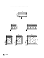
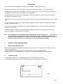
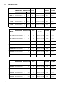
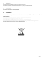
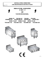
cat n° 38
INSTALLATION, OPERATING
AND MAINTENANCE INSTRUCTIONS
INDUCTION COOKERS
V 400 / 3
GB
700 PROFESSIONAL
WOK-70 702-M-I-D 702-M-I 704-M-I
ESWOK-70 ES702-M-I-D ES702-M-I ES704-M-I
WOK-70-2P WOK-70-6K WOK-70-3K
702-IND-7K 702-IND-12K 702-IMD-3K 702-IND-6K
mixerset07
CONTENTS
System plans
General instructions
I.
INSTALLATION INSTRUCTIONS
1.
1.1
1.2
1.3
1.4
1.5
1.6
1.7
2.
3.
Installation instructions
Technical plate
Technical data
Technical features
General notes at delivery
Handling
Packaging
First start
Electric safety standards
Electric connection
II.
OPERATING INSTRUCTIONS
1.
1.1
1.2
1.3
1.4
1.5
1.6
1.7
1.8
1.9
1.10
Induction generator
Fields of use
Caution! Hazard!
Personnel qualification and training
Hazards caused by failure to observe the safety regulations
Safe usage
Safety of the user or personnel responsible for use
Safety of the personnel responsible for use
Safety during installation, maintenance and controls
Reproduction or use of unauthorised spare parts
Improper usage
III.
ELECTRIC OVEN OPERATING INSTRUCTIONS
1.
1.1
1.2
1.3
2.
3.
4.
5.
6.
7.
8.
8.1
9.
10.
11.
12.
13.
Product - Technical data
Description of the product
Type and technical data
Running
Certifications
Transport
Installation
Pots and pans
Starting up
Switch off
Cleaning and maintenance
Cleaning the glass
Procedure to follow if the appliance is not going to be used for some time
Procedure to follow in the event of a breakdown
Assistance
Spare parts
Junk removal
Page 2
Page 3
Page 6
Page
Page
Page
Page
Page
Page
Page
Page
Page
Page
7
7
8
9
9
9
9
9
9
10
Page
Page
Page
Page
Page
Page
Page
Page
Page
Page
Page
11
11
11
11
11
11
11
12
12
12
12
Page
Page
Page
Page
Page
Page
Page
Page
Page
Page
Page
Page
Page
Page
Page
Page
Page
13
13
13
13
14
14
14
14
15
15
15
15
15
16
17
17
17
SYSTEMS PLAN
( WOK-70, 702-M-I-D, 702-M-I, 704-M-I )
= V 400-3N
Page 3
( ESWOK-70, ES702-M-I-D, ES702-M-I, ES704-M-I )
= V 400-3N
Page 4
( WOK-70-2P, WOK-70-6K, WOK-70-3K, 702-IND-7K, 702-IND-12K, 702-IND-3K, 702-IND-6K )
= V 400-3N
Page 5
GENERAL INSTRUCTIONS
• Read the instructions contained in this booklet carefully as they provide important
information to ensure safe installation, use and maintenance.
• Keep this booklet for any further reference by the operators.
• After removing the packing, check that the appliance is not damaged.
• Should you have any doubts, don’t use the appliance and address to skilled technicians.
• Never leave the packing components (plastic bags, foamed polystyrene, nails, etc.) within the
reach of children since they are a source of potential danger.
• Before connecting the appliance check that the specifications indicated on the data plate (Pic. 1)
correspond to those indicated on the electrical mains system.
• The appliance should be used by trained personnel only.
• Before carrying out any cleaning or maintenance operations, insulate the appliance from the
electrical mains system.
• In case of damage or malfunctioning, always disconnect the appliance.
• Any repair intervention should be carried out only by an authorized after-sale servicing centre.
• Always request the use of original spare parts.
• The non-compliance with the above mentioned instructions may compromise the safety of the
appliance.
• This appliance must be used for the purpose for which it was designed.
• The installation should be carried out by qualified personnel in compliance with the instructions
provided by the manufacturer and with the regulations in force.
• Never wash the appliance with direct high-pressure bolts of water.
• Don’t obstruct the openings and the heat inlets and outlets.
• Always keep all the appliance elements clean to avoid any risk of corrosion or any damage by
irritating agent.
• Always disconnect the appliance when it is not in use.
• Electric safety of this appliance is assured only when it is properly connected to an efficient
earthing system, as provided by the electric safety regulations in force.
• It is necessary to check this basic safety qualification of the system by highly skilled personnel.
The manufacturer cannot be considered responsible for any damages caused by the non-earthing
of the installation.
• As for the electric system it is necessary to provide for a switch having a controls opening
distance equal or superior to 3 mm: for example:
- manual switch of proper capacity equipped with plug fuses;
- automatic switch with proper magnetothermic relays.
• The appliance is to be furthermore included in an equipotential system, whose efficiency must be
checked following the regulations in force.
• The connection is made by a ven marked by " Equipotential "
• The trailing cable for the connection to the electric line should have lower characteristics than the
one with H07RN-F rubber insulation.
Page 6
ATTENTION
• This instruction manual is referred to " INDUCTION COOKERS " 700 Professional series.
• It is necessary to refer to it for any information concerning the appliance installation, use and maintenance.
• The Manufacturer declines any responsibility for damages resulting from the non-observance of the operating and
installation instructions or from an unsuitable use of the appliance.
• The Manufacturer doesn’t assume any responsibility in case the appliance connection shouldn’t be carried out
according to the regulations in force.
• This manual must be kept for all the life of the appliance and it should be kept at the disposal of the users in case of
need.
• The manufacturing co. declines every responsability for possible mistakes contained in this booklet imputable to
printing or transcription errors.
• It also reserves the right to bring changes to the product if retained useful or necessary whitout jeopardizing the
essential characteristics.
• The manufacturing co. declines any responsability for damages caused directly or indirectly due to erroneous
assembly, tampering, bad maintenance, lack of skill.
N.B. : “ If the equipment is placed against walls, dividing panels, wooden furnitures, etc....., these must be
of fire-proof material; if not, these must be covered with fire-proof material. In case of central
positioning of the equipment, their rear part should be protected with cohibented panels in order to
prevent accidents due to burns. Fire preventions rules must be carefully followed.
I.
INSTALLATION INSTRUCTIONS
1.
INSTALLATION INSTRUCTIONS
• Before proceeding with the installation peel off the protection film, remove any residual with a product suitable to
clean the stainless steel.
• Install the equipment orizontally obtaining the correct level bu means of the adjustable feet.
• The equipment can be installed alone or in a set taking care not to place it beside combustible products.
1.1
TECHNICAL PLATE
• The identification plate (Pic. 1) is positioned externally, on the left side of the machine.
• The identification plate indicates all machine data necessary in case of failure or maintenance.
Pic. 1
Page 7
1.2
TECHNICAL DATA
MODEL
DIMENSIONS GENERATORS
V. - Hz.
W EIGHT
VOLUME
Kg
m³
mm
nr.
Kw.
Kw.
WOK-70
400x700x900H
1
3
3
400/3N+T 50-60
50
0,38
702-M-I-D
400x700x900H
1
3
3
400/3N+T 50-60
56
0,38
702-M-I
400x700x900H
2
3,5
7
400/3N+T 50-60
56
0,38
704-M-I
800x700x900H
4
3,5
14
400/3N+T 50-60
102
0,75
MODEL
DIMENSIONS GENERATORS
mm
TOTAL
V. - Hz.
WEIGHT
VOLUME
Kg
m³
nr.
Kw.
Kw.
WOK-70-2P 400x1400x900H
2
3
6
400/3N+T 50-60
100
0,76
WOK-70-6K 400x1400x900H
2
3
6
400/3N+T 50-60
106
0,76
WOK-70-3K 400x1400x900H
1
3
3
400/3N+T 50-60
106
0,76
702-IND-7K 400x1400x900H
2
3,5
7
400/3N+T 50-60
106
0,76
702-IND-12K 400x1400x900H
2
6
12
400/3N+T 50-60
106
0,76
702-IND-3K 400x1400x900H
1
3
3
400/3N+T 50-60
106
0,76
702-IND-6K 400x1400x900H
1
6
6
400/3N+T 50-60
106
0,76
WEIGHT
VOLUME
Kg
m³
MODEL
DIMENSIONS GENERATORS
TOTAL
V. - Hz.
mm
nr.
Kw.
Kw.
400x700x270H
1
3
3
400/3N+T 50-60
32
0,38
ES702-M-I-D 400x700x270H
1
3
3
400/3N+T 50-60
32
0,38
ES702-M-I
400x700x270H
2
3,5
7
400/3N+T 50-60
32
0,38
ES704-M-I
800x700x270H
4
3,5
14
400/3N+T 50-60
42
0,75
ESWOK-70
Page 8
TOTAL
1.3
TECHNICAL FEATURES
• Glazed 18/10 stainless steel .
• Feet adjustable in height in stainless steel.
1.4
GENERAL NOTES AT DELIVERY
• On delivering it is necessary to check:
- the external packaging conditions;
- the general conditions of the machine;
- the conformity of this model with the data on the identification plate and in the users’manual;
- the conformity of the machine and its components with the order.
In case you have problems with the machine run, please apply to the reponsible of this supply.
1.5
HANDLING
• The instrument should be handled with a fork lift truck, but care should be taken not to damage the parts positioned
on the bottom of the instrument.
• Do not drag the instrument on the floor because you could damage the internal or external parts.
• When handling the instrument, protect your hands with heavy gloves.
1.6
PACKAGING
• Be careful not to damage the machine when you take it out of the packaging.
• Remove the protection film and clean the eventual glue marks with petrol or kerosene, don’t smoke, carry out the
operation away from heat sources.
• Do not spread in the environment or leave at children’s reach the packaging material.
1.7
FIRST START
• Clean the machine as indicated in the " Cleaning and Maintenance " chapter.
2.
ELECTRIC SAFETY STANDARDS
• The electric safety of the machine will be guaranteed only if the following basic conditions are respected:
- the power supply must be the same as the one indicated on the plate (± 10 %);
- connection to a suitable earth plug;
- connection to an equipotential protection system;
- connection to a switch complete with fuses for each pole;
- connection to a differential magnetothermic switch.
• Insert the plug into the socket or directly into the electric system ( with the apposite protection ).
• The cable does not have to be subjected to traction.
The manufacturer cannot be held responsible for eventual damages or losses caused by not having
operated in accordance both with the a.m. basic warnings and with all other conditions relating to the use
and the maintenance contained herein.
Page 9
3.
ELECTRIC CONNECTION
• The electric connection must be performed by authorized pesonell in accordance with CEI standards.
• Before connecting the appliance check that the specifications indicated on the data plate (Pic. 1) correspond to
those indicated on the electrical and gas mains system.
• The electric connection is fixed type.
• Electric safety of this appliance is assured only when it is properly connected to an efficient earthing system, as
provided by the electric safety regulations in force.
• As for the electric system it is necessary to provide for a switch having a controls opening distance equal or superior
to 3 mm: for example:
- manual switch of proper capacity equipped with plug fuses;
- automatic switch with proper magnetothermic relays.
• It is necessary to check this basic safety qualification of the system by highly skilled personnel.
• The manufacturer cannot be considered responsible for any damages caused by the non-earthing of the
installation.
• The appliance is to be furthermore included in an equipotential system, whose efficiency must be checked following
the regulations in force.
• All equipments, when supplied without cable, must be connected with cable with a section suitable for the maximum
charge.
• In case the item is placed against a wall make sure that the latter is made of fire-proof material or high temperatures
resistant, in defect leave a 100 mm. space in between or insert a fire-proof insulating panel.
• The equipment must be included in a equipotential system : the connection is made through a terminal marked by
the symbol (
) situated close to the terminal. The equipotential wire must have a minimum section of 6 mm².
WARNING: NEVER DISCONNECT THE EARTH WIRE (yellow-green)
• It is essential to earth the appliances: for this reason, it is necessary to connect the terminals marked by the
symbols (PE ;
) placed by the line arrival terminal boards to an efficient earthing, realised according to the
regulations in force.
THE MANUFACTURER DOESN’T ASSUME ANY RESPONSIBILITY IN CASE THIS SAFETY RULES
SHOULDN’T BE RESPECTED.
Page 10
II.
OPERATING INSTRUCTIONS
1
SAFETY
1.1
FIELDS OF USE
Induction generators can be installed in fitted hobs and free-standing cookers and should be used for cooking, heating,
keeping things warm and roasting.
All the specific saucepans recommended for use for induction cooking can be used with induction generators, such as
saucepans in cast iron and chrome-plated iron, as well as enamelled pans.
They should have a diameter of between 16 and 26 cm.
Induction generators should not be used to heat objects other than those listed above.
1.2
CAUTION - HAZARD
CAUTION
Incorrect usage and failure to comply with the instructions provided could cause injury or damage to people and
property.
CAUTION
Before using or carrying out maintenance work on the appliance, please read this use, maintenance and installation
manual carefully.
HAZARD
Failure to follow the relative safety regulations, laws and directives could expose you to hazard.
HAZARD
The incorrect use or handling of the generators poses a hazard to people, animals and property.
Failure to ready and study this use and installation manual exposes you to hazard
1.3
PERSONNEL QUALIFICATION AND TRAINING
The personnel responsible for installing, commission, using and maintaining the appliance must be QUALIFIED or
AUTHORISED by the manufacturer.
1.4
HAZARDS CAUSED BY FAILURE TO OBSERVE THE SAFETY REGULATIONS
Failure to observe the safety regulations can pose a hazard to people to the surrounding environment and the induction
generator itself. Failure to observe the safety regulations causes the guarantee to become null and void, meaning that
you will no longer be entitled to replacements for damaged parts. In particular, failure to observe the regulations entails:
·
risks of all kinds to people and property.
·
hazards of all kinds to people and property.
1.5
SAFE USAGE
It is important to observe the safety regulations in the manual, and the relative national and international laws and
regulations regarding electrical safety, national and international laws and regulations regarding safety in the workplace,
and national and international laws and regulations on accident prevention.
1.6
SAFETY OF THE USER OR PERSONNEL RESPONSIBLE FOR USE
Electrical hazards should be excluded. The induction generator should be used by qualified personnel and it should be
installed by a certified professional in compliance with specific international, national and regional regulations on electrical
and electronic appliances for collective use and civil and industrial electrical installations.
Page 11
1.7
SAFETY OF THE PERSONNEL RESPONSIBLE FOR USE
The pyroceram area is heated by the heat of the saucepan.
To avoid burns, do not touch the heating zone.
To avoid excessive overheating, do not leave the empty saucepan on the heat or heat it for no reason.
When cooking with several saucepans at the same time, make sure that the handles do not cross each other and that
they are outside the field of induction.
The handles may become very hot depending on the type of material of which they are made.
Risk of burns! We recommend using oven gloves.
Saucepans must always be kept a small distance apart.
They should not touch each other.
When you remove the saucepan, it is advisable to switch off the cooking zone to prevent the heating system from
switching back on automatically should you happen to replace the saucepan.
Do not place other material (paper, card, fabric, etc.) between the saucepan and the cooking zone as it could catch fire.
Metal objects heat up very quickly if placed in the heating zone when it is in operation.
It is therefore advisable not to place objects other than saucepans on the induction hob (cans, closed tins, aluminium
trays, cutlery, rings, keys, watches, etc.)
People with pace makers should consult their doctor to find out whether they can work in the vicinity of a hob with
induction generator.
Do not place credit cards, phone cards, tapes or other magnetic objects on the pyroceram plate with induction system.
The induction generator has an internal cooling system.
Make sure that the air inlet and outlet holes are not blocked by objects (paper, rags or other).
This could cause overheating and lead the induction generator to switch itself off.
Do not allow liquids (water, oil or other) to enter the induction generator.
Do not clean the generator with a jet of water.
If the pyroceram top is cracked or broken, switch off the generator and disconnect the electricity supply.
Do not touch any of the internal parts of the induction generator.
1.8
SAFETY DURING INSTALLATION, MAINTENANCE AND CONTROLS
The personnel responsible for use must be qualified.
All installation, maintenance and control operations must be performed by personnel qualified to issue the relative
certificates requested by the relative authorities as regards safety
in the workplace.
Said personnel must study this manual in depth.
Only highly qualified personnel may install, maintain, service, repair and collect the induction generator component.
Said personnel must be trained by means of a specific training course authorised by the manufacturer as regards the
induction generator.
Moreover, they must meet the requirements set by the relative authorities as regards the electrical and electronic safety
of installations.
Generally speaking, work should only be carried out on the induction generator component after it has been disconnected
from the electricity supply.
The induction generator must be switched off and disconnected from the power supply and electricity network.
The safety and protection installations must be replaced and reinstalled at the end of the above operations, according
with the international, national and regional regulations and laws on safety, thus ensuring correct and safe usage of the
component.
1.9
REPRODUCTION OR USE OF UNAUTHORISED SPARE PARTS
Reproductions or changes to the induction generator component are not permitted.
Contact the manufacturer if you observe any changes to the induction generator.
To ensure safety, always use original spare parts, authorised by the manufacturer.
The manufacturer declines responsibility in the event in which non-original spare parts have been used.
1.10
IMPROPER USAGE
The proper working order of the induction generator components is only guaranteed in the event of correct usage as
described in this manual and as regulated by the international, national and regional laws and regulations on safety and
electromagnetic compatibility, which regulate components such as the induction generator.
Page 12
III.
TECHNICAL FEATURES
1.
PRODUCT - TECHNICAL DATA
1.1
DESCRIPTION OF THE PRODUCT
The electromagnetic induction generators are used in professional catering.
Thanking to their compact dimensions they can be used in cooking plans and in support ovens with small dimensions
and they can be mounted in professional kitchen.
The electronic parts of the induction generator are covered by many protections in order to prevent any damages.
Thanking to this protections no noise can be be heard even using different powers.
1.2
TYPES AND TECHNICAL DATA
-Type RELD V3S R6000-R6000
-Power (KW) 12000 Watt
-Voltage(VAC): 400 VAC/3F+N+T
-Current (A): 8.6 Ampère
-Frequency (HZ):50/60 Hz
-Dimensions: See technical layouts
-Thickness:ceramic glass:6 mm
-Derating insertion :0 kw at 220°on the coil
-Maximum temperature equipment: as for EN standard
TYPE WOK
-Type: REBS: V3S W6000
-Power (KW): 6000 Watt
-Voltage(VAC): 400 VAC/3F+N+T
-Current (A): 8.6 Ampère
-Frequency (HZ):50/60 Hz
-Dimensions: See technical layouts
-Thickness:ceramic glass:6 mm
-Derating insertion :0 kw at 220°on the coil
-Maximum temperature equipment: as for EN standard
1.3
RUNNING
Max tolerance in voltage:
Rated Voltage:+6%
Rated Voltage:-10%
Frequency (HZ):50/60 Hz
Minimum diameter of the pan:160 mm
Environnment temperature range: from +5° to +40°
Max dampness air : from 30% to 90%
Page 13
2.
CERTIFICATIONS
The induction generators must be considered “components” and not “finished products” and so they are submittted to
the controls of the IMQ, “Istituto del Marchio di Qualità”(Quality Brand Institution), in order to obtain the SCV-IMQ, the
“certificato di sorveglianza” ( “the supervision certificate” ) according to the following regulations:
STANDARD ON ELECTROMAGNETIC COMPATIBILITY
EN 61000 3-2::1995+A1; 1998+A2: 1998+A14: 2000
EN 61000 –3-3 1995
EN 55011: 1998
EN 55014: 1997
STANDARD ON ELECTRIC APPLIANCE FOR COLLECTIVE UTILISATION AND SIMILAR
En 60335-2-36: 2000 (PAR 10,17, 19.11, 24,25,26)
mark CSV-IMQ
3.
TRANSPORT
-The induction generators are carefully packed.Handle with care, and check the conditions of the packaging as soon as
you receive the goods. In case of damage, please contest the forewarder at the soonest.
-Storage: if the induction generator is not installed immediately, please store it without removing the packaging, at a
temperature range between 20° and 50° and dampness from 10% to 90%.
-Remove the packaging only in case of immediate installation.
-Keep the packagings materials in case of return of the goods to the supplier.
4.
INSTALLATION
The induction generators must be considered “components” and not “finished products” so you must respect the laws,
the regulations and the standards in force in the different countries as far as low and medium voltage are concerned.
You also must respect the regulations on security of electric appliances for collective utilisation and the regulations on
electromagnetic compatibility.
To find copy of these regulations please contact the authorized institutions in the different countries where the installations
will be done.
Each generator is equipped with its electric layout showing the harness and its relatives connections.
On the layouts there are all the indications and all the references you can find also in the electrical and electronic
parts, in order to avoid any mistake in connecting the parts.
The layouts are attached to this manual”
5.
POTS AND PANS
Induction generators only work properly with saucepans with an iron, cast iron or chrome-plated iron base.
These pans may also be enamelled.
The generators accept all the above type of saucepans and adapt in real time to supply the same power.
The pans must have a diameter of between 160 mm and 260 mm.
It is best for the bans to have a flat base.
The generator does not accept unsuitable pans.
Any other product no mentioned in this paragraph should be considered automatically excluded and unsuitable for use
with induction generators.
Page 14
6.
STARTING UP
CAUTION: The heating zone is heated by the heat emanated by the base of the saucepan. To avoid burns
and injury, do not touch the heating zone.
a)
Connect the appliance to the power supply after making sure that the voltage corresponds to that used by the
induction generator and indicated on the manufacturer’s plaque.
b)
Place the saucepan directly above the cooking zone where the inductors are located.
c)
Turn the knob/potentiometer in a clockwise direction. To activate the power supply: the GREEN LED turns on.
Absence of the saucepan: the GREEN LED flashes.
d)
Select the desired power using the knob/potentiometer, which will set the power immediately.
When you remove the pan for awhile, the inductor will stop supplying power, and when you replace the pan the
power will be restored immediately at the same level as before.
For safety reasons, if the pan is removed for more than 600 seconds, the induction is switched off completely
and will need to be switched back on if the pan is replaced, restoring the knob/potentiometer to the “OFF”
position and then back to the desired power by turning the knob in a clockwise direction.
7.
SWTCH OFF
-
8
Turn the knob/potentiometer in a clockwise or anticlockwise direction until it is in the rest position [OFF]
Certain parts of the generator are still powered even when the cooker is switched off.
Therefore, if carrying out maintenance work, disconnect the appliance from the power supply first.
Make sure that no liquid penetrates the induction generator, either during normal use or during cleaning and
maintenance of the component.
CLEANING AND MAINTENANCE
CAUTION: During cleaning, do not wash the external parts of the appliance with direct or high pressure
water jets.
Every evening, after use, clean the appliance thoroughly.
Daily cleaning after switching off the appliance ensures the perfect functioning and long life of the appliance.
Before starting to clean the appliance, disconnect the power supply.
The steel parts must be washed with hot water and neutral detergent, then rinsed thoroughly in order to eliminate all
traces of detergent.
They should then be dried with a dry cloth.
Do not use abrasive or corrosive detergents.
8.1
CLEANING THE GLASS
The glass should be washed with vinegar or lemon-based degreasers, suitable for cleaning ceramics and glass.
During this operation, it is best for the glass not to be completely cold, so that spilt food, burnt fat and other substances
can be softened with a damp cloth and removed whilst still warm with a scraper, so as to prevent the glass surface from
deteriorating.
Do not use abrasive or corrosive detergents.
9.
PROCEDURE TO FOLLOW IF THE APPLIANCE IS NOT GOING TO BE USED FOR SOME TIME
Clean and dry the appliance carefully according to the instructions. Disconnect the power supply.
Page 15
10.
PROCEDURE TO FOLLOW IN THE EVENT OF A BREAKDOWN
− CAUTION: NEVER carry out any work on the induction generators without first having disconnected them from the
power supply .
− HAZARD: high voltage present in induction generators powered by the electricity supply .
− The induction generators should only be opened by QUALIFIED, AUTHORISED PERSONNEL IN COMPLIANCE
WITH INTERNATIONAL, NATIONAL AND REGIONAL SAFETY LAWS AND REGULATIONS.
TYPE OF FAULT
POSSIBLE CAUSE
STEPS TO BE TAKEN
Green LED off
Red LED off.
No power
Check that the generator is connected to
the power supply
Green LED on
Red LED off.
Make s u re you have turned the knob in
a clockwise direction
Turn the knob
Make s u re you have pos itionned the
suitable saucepan correctly
Pos ition a suitable saucepan correctly
Defect control form
Call a technician
No heating
Green LED flas h ing
Red LED off.
No heating (the power part of the generator is too hot)
Green LED on
Red LED on
Air inlet or outlet blocked.
Check and clean air inlet and outlet
Defective fan
Call a technician
Unsuitable saucepan
Use a suitable saucepan
No heating (the induction component under the pyroceram is too hot)
Green LED on
Red LED flashing
Green LED flas h ing
Red LED off.
Empty cooking protection triggered it to
cool down. The fan is o ver 220°C.
Verify that the generatur is power
supplied
Cooking point sensor defective
Call a technician
Saucepan diam e ter under 160 m m
saucepan.
Use a suitable saucepan
Saucepan not pos itioned correctly and
thus not recognised
Pos ition the saucepan correctly
The power component is too hot and
has s w itched on the power reduction
autom a tically
Make s u re that the saucepan is s uitable.
Poor heating
Green LED on
Red LED flashing
Green LED on
Red LED on
Internal tem p e rature high due to
ins u fficient cooling
Unsuitable saucepan
Replace with a s u itable saucepan
Fas t increase in pyroceram
temperature. You m a y be us ing an
e m p ty saucepan
Adjus t the power on the bas is of the
quantity of food
Heating of small metal objects on the zone
Green LED flas h ing
Red LED off
Page 16
Saucepan recognition not correctly
regulated
Call a technician
11.
ASSISTANCE
The user must be sure that all the components always work properly
The induction generators must be checked at least once a year by a qualified technician.
12.
SPARE PARTS
The customer can’t install or replace spare parts.
13.
JUNK REMOVAL
When a component of induction generator is out of use , it must be removed properly in compliance with the regional,
national, international regulations in force in the different countries as far as junk removal is concerned.
Avoid improper use:
The components of induction generators must not be used by unauthorized personnel.
Prevent any component ready to be removed to work again.
These components are made of electric, electronic, mechanic, electromechanic parts
The user is responsible of the safe and correct removal of the induction generator and of its components too.
Any kind of maintenance must only be done by qualified personnel.
Page 17