1
SEARS
®
MODEL NUMBER 917.257711
OWNER'SMANUAL
• Assembly
° Operation
° Customer Responsibilities
Service and Adjustments
"Repair Parts
CAUTION:
Read and follow all safety rules and instructions
before operating this equipment°
m
SAFETY
Practices RULES
for Ride-On
Safe Operation
IMPORTANT:
THIS CUTTING MACHINE IS CAPABLE
OBJECTS.
FAILURE TO OBSERVE THE FOLLOWING
INJURY OR DEATH.
I. GENERAL OPERATION
,,
o
•
,'
,,
•
,'
,,
•
,,
,,
o
•
,,
•
ft.
OF AMPUTATING HANDS AND FEET AND THROWING
SAFETY INSTRUCTIONS COULD RESULT IN SERIOUS
III, CHILDREN
Tragic accidents can occur if the operator is not alert to the
presence of children. Children are often attracted to the machine
and the mowing activity. Never assume that children will remain
where you last saw them.
Read, understand, and follow all instructions in the manual
and on the machine before starting.
Only allow responsible adults, who are familiar with the
instructions, to operate the machine.
Clear the area of objects such as rocks, toys, wire, etc.,
which could be picked up and thrown by the blade.
Be sure the area is clear of other people before mowing. Stop
machine if anyone enters the area.
Never carry passengers.
Do not mow in reverse unless absolutely necessary. Always
look down and behind before and while backing.
Be aware of the mower discharge direction and do not point
it at anyone. Do not operate the mower without either the
entire grass catcher or the guard in place.
Slow down before turning.
Never leave a running machine unattended. Always turn off
blades, set parking brake, stop engine, and remove keys
before dismounting.
Turn off blades when not mowing.
Stop engine before removing grass catcher or unclogging
chute.
"
•
Before and when backing, look behind and down for small
children.
•
Never carry children. They may fall off and be seriously
injured or interfere with safe machine operation.
Never allow children to operate the machine.
Use extra care when approaching blind corners, shrubs,
trees, or other objects that may obscure vision.
•
,,
Mow only in daylight or good artificial light.
Do not operate the machine while under the influence of
alcohol or drugs.
Watch for traffic when operating near or crossing roadways.
Use extra care when loading or unloading the machine into
a trailer or truck.
IV.
SERVICE
e
Use extra care in handling gasoline and other fuels. Theyare
flammable and vapors are explosive.
Use only an approved container.
Never remove gas cap or add fuel with the engine
running. Allow engine to coo! before refueling. Do not
smoke.
Never refuel the machine indoors.
Never store the machine or fuel container inside where
there is an open flame, such as a water heater.
Never run a machine inside a closed area.
SLOPE OPERATION
DO:
Mow up and down slopes, not across.
Remove obstacles such as rocks, tree limbs, etc.
•
•
Q
Watch for holes, ruts, or bumps.
Uneven terrain could
overturn the machine. Tall grass can hide obstacles.
e
Use slow speed. Choose a low gear so that you will not have
to stop or shift while on the slope.
o
Follow the manufacturer's
recommendations
for wheel
weights or counterweights to improve stability.
o
Use extra care with grass catchers or other attachments.
These can change the stability of the machine.
o
Keep all movement on the slopes slowand gradual. Do not
make sudden changes in speed or direction.
o
Avoid starting or stopping on a slope. If tires lose traction_
disengage the biades and proceed slowly straight down the
slope.
DO NOT:
o
•
,
•
"
Keep nuts and bolts, especially blade attachment bolts, tight
and keep equipment in good condition.
Never tamper with safety devices.
Check their proper
operation regularly.
Keep machine free of grass, leaves, or other debris build-up.
Clean oil or fuel spillage.
Allow machine to cool before
storing.
Stop and inspect the equipment if you strike an object.
Repair, if necessary, before restarting.
Never make adjustments or repairs with the engine running.
Grass catcher components are subject to wear, damage, and
deterioration, which could expose moving parts or allow
objects to be thrown. Frequently check components and
replace with manufacturer's recommended parts, when necessary.
Mower blades are sharp and can cut. Wrap the blade(s) or
wear gloves, and use extra caution when servicing them.
Check brake operation frequently. Adjust and service as
required.
I
|
I
Do not turn on slopes unless necessary, and then, turn slowly
and gradually downhill, if possible.
Do not mow near drop-offs, ditches, or embankments. The
mower could suddenly turn over if a wheel is over the edge
of a cliff or ditch, or if an edge caves in.
Do not mow on wet grass. Reduced traction could cause
sliding.
Do not try to stabilize the machine by putting your foot on the
ground.
Do not use grass catcher on steep slopes.
Keep children out of the mowing area and under the watchful
care of another responsible adult.
Be alert and turn machine off if children enter the area.
•
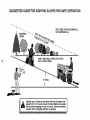
Slopes are a major factor related to loss-of-control and tipover
accidents, which can result in severe injury or death. All slopes
require extra caution. If you cannot back up the slope or if you feet
uneasy on it, do not mow it.
e
Mowers
Look for this symbol to point out important safety
precautions.
It means
CAUTION!!!
BECOME ALERT!!!
YOUR
SAFETY
CAUTION:
IS INVOLVED.
Always
=.__J
disconnect
spark
contact spark plug in order to prevent
plug
wire andstarting
place wire
where
it cannot
accidental
when
setting
up,
transporting,
adjusting
or making
repairs.
2
!
I
|
|
i
m
CONGRATULATIONS
on your purchase of a Sears
Tractor. It has been designed, engineered and manufactured to give you the best possible dependability and
performance.
Should you experience any problem you cannot easily
remedy, please contact your nearest Sears Authorized
Service Center/Department.
We have competent, welltrained technicians and the proper tools to service or repair
this tractor.
Please read and retain this manual. The instructions will
enable you to assemble and maintain your tractor properly.
Always observe the "SAFETY RULES".
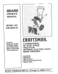
PRODUCT
SPEC NCATiONS
HORSEPOWER:
l&0
GASOUNE CAPACITY
AND TYPE:
3.5 GALLONS
UNLEADED REGULAR
OrL TYPE (API--SFiSG):
SAE 30 (above 32°F)
SAE 5W-30 (below 32°F)
OIL CAPACITY:
3.0 PINTS
CHAMPION
STD361458
RJ-19LM
VALVE CLEARANCE:
INTAKE:
EXHAUST:
.004" - .006"
.007" ° .009"
GROUND SPEED (MPH):
Fowvard
1st
2nd
3rd
Reverse
DATE OF PURCHASE
TRANSAXLE OIL
CAPACITY AND TYPE:
4 QUARTS
SAE 30 API-SF/SG
THE MODEL AND SERIAL NUMBERS WILL BE FOUND
ON A PLATE UNDER THE SEAT.
TiRE PRESSURE:
FRONT:
REAR:
YOU SHOULD RECORD BOTH SERIAL NUMBER AND
CHARGING SYSTEM:
5 AMPS BATTERY
5 AMPS HEADLIGHTS
BLADE BOLT TORQUE:
30-35 FT. LBS.
MODEL
NUMBER
SPARK PLUG:
(GAP: .030")
9! 7.257711
SERIAL
NUMBER
l DATE OF PURCHASE AND KEEP iN A SAFE PLACE
_RE
REFERENCE.
MAINTENANCE
AGREEMENT
A Sears Maintenance
Agreement
uct. Contact your nearest Sears
CUSTOMER
RESPONStBiUTIES
Read and observe
,
is available on this prodstore for details.
the safety
Follow a regular schedule
using your tractor.
rules.
in maintaining,
caring for and
Follow the instructions
under "Customer
Responsibilities" and Storag_
sections of this owner's manual.
LIMITED TWO YEAR WARRANTY
LO
0.8
1.4
2.4
0.9
H_
1.8
3.4
5.6
2.2
!4 PSi
10 PSi
WARNING:
This tractor is equipped with an internal
combustion engine and should not be used on or near any
unimproved forest-covered, brush-covered or grass-coy _
ered land unless the engine's exhaust system is equipped
with a spark arrester meeting applicable local or state laws
(if any). if a spark arrester is used, it should be maintained
in effective working order by the operator.
In the state of California the above is required by law
(Section 4442 of the California Public Resources Code),
Other states may have similar laws. Federal laws apply on
federal tands. A spark arrester for the muffler is available
through your nearest Sears Authorized Service Center/
Department (See REPAIR PARTS section of this manual).
ON ELECTRIC
START RIDING EQUIPMENT
For two (2) years from the date of purchase, if this riding equipment is maintained, lubricated and tuned up according to the
instructions in the owner's manual, Sears will repair or replace, free of charge, any parts found to be defective in material or
workmanship.
This Warranty does not cover:
o
o
Expendable items which become worn during normal use, such as blades, spark plugs, air cleaners and belts.
Tire replacement or repair caused by punctures from outside objects, such as nails, thorns, stumps, or glass.
Repairs necessary because of operator abuse, negligence, improper storage or accident or the failure to maintain the
equipment according to the instructions contained in the owner's manUall
Riding equipment used for commercial or rental purposes.
LIMITED 90 DAY WARRANTY
ON BATTERY
For ninety (90) days from date of purchase, if any battery included with this riding equipment proves defective in material or
workmanship and our testing determines the battery will not hold a charge, Sears wi!l replace the battery at no charge.
WARRANTY SERVICE
CENTER/DEPARTMENT
tS AVAILABLE BY RETURNING
IN THE UNITED STATES.
THE RiDiNG
EQUIPMENT
TO THE NEAREST
SEARS SERVICE
This Warranty gives you specific legal rights, and you may also have other rights which may vary from state to state.
SEARS,
ROEBUCK
AND CO., D/817 WA, HOFFMAN
ESTATES,
ILLINOIS
60179
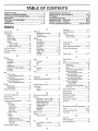
TABLE OF CONTENTS
SAFETY RULES ............................................................
2
PRODUCT SPECiFiCATIONS ......................................
3
CUSTOMER RESPONSIBILITIES ..................... 3, 15-18
WARRANTY ..................................................................
3
TRACTOR ACCESSORIES ..........................................
5
ASSEMBLY .............................................................
740
OPERATION ..........................................................
11-14
MAINTENANCE SCHEDULE .....................................
15
SERVICE AND ADJUSTMENTS ........................... t9-25
STORAGE ...................................................................
26
TROUBLESHOOTING ...........................................
28-29
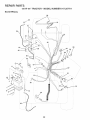
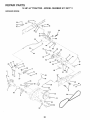
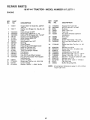
REPAIR PARTS =TRACTOR ................................ 30-47
REPAIR PARTS = ENGINE ....................................
48-53
PARTS ORDERING/SERVICE ............... BACK COVER
INDEX
E
A
Accessories ...........................................
Adjustments:
Brake ............................................
Carburetor ....................................
Clutch Pulley ................................
Gauge Wheels .............................
Mower
FrontoTo°Back .........................
Side-To-Side ...........................
Throttle Control Cable ..................
5
21
25
21
!3
20
19
24
Air Filter, Engine ..................................
18
Air Screen, Engine ..............................
18
Assembly ..........................................
7-10
B
Battery:
Charging ........................................
8
Cleaning .......................................
18
Installation ....................................
10
Levels ........................................
8,17
Preparation ....................................
8
Starting with Weak Battery ........... 23
Storage ........................................
26
Terminals .....................................
17
Belt:
Motion Drive
Removal/Replacement
............ 22
Mower Drive
Remova!/Replacement ............ 20
Mower Blade Drive
Removal/Replacement
............ 2!
Blade:
Sharpening ...................................
16
Replacement ................................
16
Brake Adjustment ................................ 2!
Electficah
Interlocks and Relays ................... 23
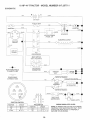
Schematic .................................... 30
Wiring Diagram ............................ 32
Engine:
Air Filter ........................................
18
Air Screen ....................................
18
Cooling Fins .................................
18
Oil Change ...................................
17
Oil Level .......................................
17
Oil Type ...................................
13,17
Preparation ..................................
13
Repair Parts ............................ 48-53
Starting .........................................
14
Storage ........................................
26
26
!3
23
H
L
C
Carburetor Adjustment ........................
Clutch Pulley .......................................
Controls, Tractor ..................................
18
18
13
Headlights ...........................................
23
Hood Removal/Installation .................. 24
Leveling Mower Deck ..........................
Lubrication:
Chart ............................................
Engine ..........................................
19
15
t7
M
25
21
11
Customer Responsibilities .............. 15-18
Engine:
Air Filter ....................................
18
Air Screen
18
Cooling Fins .............................
18
Engine Oil ........................... 13,17
Fuel Filter .................................
18
Spark Plug(s) ........................... 18
Tractor:
Battery ......................................
17
Blade ........................................
!6
Lubrication Chart ...................... 15
Maintenance Schedule ............ 15
Tire Care .......................... 8,18,21
Transaxie .................................
16
Cutting Height, Mower ......................... 12
P
Parking Brake .................................
1lq2
Parts Bag ..............................................
6
Parts, Replacement/Repair
............ 30-47
Product Specifications ........................... 3
R
Repair Parts ...................................
30-47
S
F
Filter:
Air Filter ........................................
Fuel ..............................................
Oit .................................................
Fuel:
Storage ........................................
Type .............................................
Fuse ................. i..................................
Operation .......................................
! 1-14
Operating Mower ............................. 12 3
Options:
Accessories ....................................
5
Spark Arrester ........................... 3,40
Safety Rules ..........................................
Seat .......................................................
2
8
Service and Adjustments ............... 19-25
Carburetor .................................... 25
Clutch Pulley ................................ 21
Fuse .............................................
23
Hood Removal/Installation ........... 24
Motion Drive Belt
Removal/Replacement
............ 22
Mower Drive Belt
Removal/Replacement
............ 20
Mower Blade Drive Belt
Removal/Replacement
............ 21
Mower Adjustment
Front4o-Back .......................... 20
Side4o-Side ............................ 19
Mower Removal/installation ......... 19
Tire Care .............................. 8,15,23
Slope Guide Sheet .............................. 55
Spark Plug(s) ......................................
18
Specifications ........................................
3
Starting the Engine ............................. 14
Steering Wheel ................................. 7,22
Stopping the Tractor ............................ 12
Storage ................................................
26
Maintenance Schedule ....................... 15
Mower:
Adjustment, Front-to-Back ........... 20
Adjustment, Side-to°Side ............. 19
Blade Replacement ...................... 16
Blade Sharpening ........................ 16
T
Cutting Height ==============================
12
Installation .................................... lg
Throttle Control Cable Adjustment ...... 24
Operation .....................................
13
Tires ............................................
8,15,21
Removal .......................................
19
Troubleshooting Chart .................... 28-29
Mowing Tips ........................................
14
Transaxle ............................................
16
Muffler .................................................
!8
Spark Arrester ........................... 3,40
W
O
Oih
Cold Weather Conditions ........ 13,17
Engine .........................................
17
Storage ........................................
26
Warranty ................................................
Wiring Diagram ...................................
Wiring Schematic ................................
3
32
30
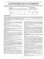
These accessories
Most Sears stores
and attachments
can order these
were available through most Sears retai_ outlets and service centers
items for you when you provide the model number of your tractor.
when
the tractor
was purchased.
ENGINE
SPARK
PLUG
BLA_:)ES
BELTS
PERFORMANCE
Sears offers a wide variety of attachments
that fit your tractor.
you. This list was current at the time of publication;
however,
may be made in these attachments,
or some may no longer
accessories
and attachments
that are available
for your
Many of these are listed below with brief explanations
of hew they can help
it may change n future years - more attachments
may be added, changes
be available or fit your model.
Contact
your nearest
Sears store for the
tractor,
Most of these
or conversion
attachments
do not require
additional
hitches
kits (these
that do are indicated)
and are designed
for easy
attaching and detaching.
AERATOR
promotes deep root growth for a healthy lawn. Tapered
2.5-inch steel spikes mounted on t0qnch diameter discs puncture
holes in soil at close intervals to let moisture soak in Steel weight tray
for increased penetration
BUMPER
protects
front end of tractor
from damage
CARTS make hauling easy. Vadety of sizes available, plus accessories such as side panel kits, too! caddy, cart cover, protective mat and
dolly,
CORING AERATOR
takes small plugs out of soil to allow moisture
and nutrients to reach grass roots, 36qnch swath. 24 hardened steel
coring tips. 150 lb. capacity weight tray.
DISC NARROW has 2 gangs of 4 steel blades that angle from 10 to
20 degrees, 40 inches wide. Can hook 2 units in tandem. (Requires
sleeve hitch,)
DOZER BLADE
removes snow; grades
inches wide, 17 inches high, clears 44cinch
lift control lever for operator ease. Spring
uneven pavement; built-in float for blade
Reversible, replaceable scraper bar, (Use
weights and!or rear drawbar weight.)
dirt, sand and gravei. 48
path when angled. Master
trip for snow removal on
to follow ground contour.
with tire chains and wheel
EASY OIL DRA_N VALVE makes oil changes easier, faster,
FRONT NOSE ROLLER canters in front of mower deck to reduce
chances
of "scalping"
on uneven
terrain.
GANG HmTCH lets you tow 2 or 3 pull-behind
attachments
at
once, such as sweepers,
dethatchers,
aerators (not for use with
rollers, carts or other heavy attachments).
MULCH
RAKFJDETNATCHER
loosens soil and flips
matted leaves to lawn surface for easy pickup.
Twenty
teeth. Useful to prepare bare areas for seeding. Available
rear mounting,
N_GH PERFOR_IANCE
REEL-ACTION
TtNE DETNATDH ER covers 36-inch wide path and tosses
large hopper. Mounts behind tractor.
thatch and
spring tine
forfront or
SPR_NG
thatch into
PLOW turns soil 6 inches deep, cuts lO-inch furrow. Crank adjustment controls depth, 3-position yoke sets width, Heavy steel landside
for straight furrowing,
(Requires sleeve hitch,)
RAMP TOPS AN[:} FEET let you toad and unload
pickup truck. Use with 2 x 8 or 2 x t0 lumber,
tractor
from a
REAR GRADER BLADE is 42 inches wide and operated from driver's
seat. Reversible steel blade can be angfed at 30 degrees for grading.
Reverses for pushing snow backwards.
(Requires sleeve hitch.)
ROLLERfor
smoother lawn surface, 36-inehwide,
18qnch diameter
water-tight
drum holds up to 390 _bs. of weight,
Rounded edges
prevent harm to tud, Adjustable scraper automatically
cleans drum.
SLEEVE
CULTIVATOR
is 43 inches wide. Prepares
ground for
seeding, helps weed control. Steel frame holds 5 adjustable sweeps.
Adjusts vertically, horizontally.
(Requires sleeve hitch.) Optional
accessory:
steet furrow opener for wider openings for potatoes,
corn, and other deep-seeded
crops.
SLEEVE HITCH for use with master
uncouples.
lift system.
Single pin couples!
SNOWTHROWER
has 42-inch swath,
Drum=type auger handles
powdery and wet/heavy snow. Mounts easily with simple pin arrangement, Discharge chute adjusts from tractor seat. 6-inch diameter
spout discharges snow tO to 50 feet. Lift controlled at tractor seat.
(Use with chains and wheel weights and/or rear drawbar weight.)
SPRAYERS
use 12=volt DC e_ectric motor that connects to the tractor
battery or other t2-volt
source.
Includes booms for automatic
spraying and hand held wand for spot spraying. Wand has adjustable
spray pattern, For applying herbicides, insecticides,
fu,-igicides and
liquid fertilizers.
SPREADER/SEEDERS
make seeding, fertilizing, and weed killing
easy. Broadcast spreaders are also useful for granular de-icers and
sand,
SWEEPERS
let you collect grass clippings
and leaves,
T_LLER has 8 hp engine to prepare seed beds, cultivate, and compost
garden residue. Chain-drive transmission.
Six 11-inch diameter one
piece heat-treated
steel tines. Tills 30qnch path. (Requires sleeve
hitch.) Or use 5 hp tow-behind T_LLER with 36qnch swath to prepare
seed beds, cultivate and compost garden residue. Tiller has its own
built-in lift and depth controt system and does NOT require a sleeve
hitch. Fits any lawn, yard or garden tractor, Simply hook up to the
tractor drawbar and go! Optiona_ accessories
for 5 hp tiller convert
unit for dethatching,
aerating, hilling.,.without
toots.
T_RE CHAINS are heavy duty; closely spaced extraqarge
give smooth ride, outstanding traction.
cross links
TRACTOR CAB has heavy duty vinyl fabric over tubular stee! frame,
ABS plastic top; clear p_astic windshield offers 360 degree visibility,
Hinged metal doors with cstch_
Keep_ operator warm and dry.
Remove vinyl sides and windshields
for use as sun protector in
summer
Optionat
accessories
include:
tinted/tempered
solid
safety glass windshield
with hand operated wiper; 12-volt amber
caution light for mounting on cab top,
VACS for powertul collection of heavy grass clippings and leaves.
Option_
warld attachment
to pick up debris in hard-to-.reach places.
VACICH_PPER
includes a chipper-shredder,
WEIGHT BRACKET for drawbar for snow removal applications.
Can
be mounted on front of tractor for plowing applications.
Uses (1) 55
lb. weight.
WHEEL
removal
WEIGHTS for rear wheels provide
or dozing heavy materials,
needed traction
for snow
CONTENTS
Parts Bag contents
OF
shown full size
Parts packed
separately
in carton
÷
Seat
Batter,/acid
(1) Shoulder Bolt 5/16-18
,/
(!) Knob
Battery
Steering Wheel
(1) Washer
17/32 x 1_3/16 x 12 Gauge
Owner's Manual
Parts Bag
(3) Retainer Springs
Parts bag contents
(2) Gauge
Wheels
(4) Retainer
_
(2) Shoulder
Bolts
" (2) Battery Carriage Bolts 1/4-20 x 7-1/2
(2) Front Link Assemblies
(2) Hex Nuts 1/4-20
(2) Washers
Steering
Sleeve
Termina_ Guard
9/32 x 5/8 x 16 Ga.
(2) Lock Washers
full size
Washers
3/8 x 7/8 x 14 Gauge
(2) Crown
Lock
Nuts
Springs
@
(2) Hex Bolts 1/4-20 x 3/4
not shown
Steering
Wheel Insert
1/4
(2) Keys
(2) Wing Nuts 1/4_20
15° Slope Sheet
6
Battery Caps
and Instructions
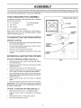
BLY
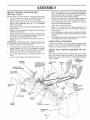
Your new tractor has been assembled at the factory with the exception of those parts left unassembled for shipping purposes.
To ensure safe and proper operation of your tractor all parts and hardware you assemble must be tightened securely. Use
the correct tools as necessary to insure proper tightness.
TOOLS REQUIRED
FOR ASSEMBLY
STEERING
WHEEL INSERT
A socket wrench set will make assembly easier, Standard
wrench sizes are listed,
(2) 7/16" wrenches
Tire pressure gauge
(1) 1/2" wrench
Utility knife
_.f
HEX BOLT
(1) 9/16" wrench
LOCK WASHER
(1) 3/4" socket with drive ratchet
When right or left hand is mentioned in this manual, it
means when you are in the operating position (seated
behind the steering wheeI).
TO REMOVETRACTOR
UNPACK
,
STEERING
LARGE FLAT
WASHER
FROM CARTON
CARTON
Remove all accessible loose parts and parts cartons
from carton (See page 6),
,
Cut, from top to bottom, along lines on all four corners
of carton, and lay panels flat.
=
Remove mower and packing materials.
STEERING
WHEEL
ADAPTER
Check for any additional loose parts or cartons and
remove.
/
/
_/
SLEEVE
/
/'-. -_--_-'_ / /
/
BEFORE ROLLINGTRACTOR
ATTACH
STEERING
WHEEL
OFF SKID
I
(See Fig. 1)
•
Position front wheels of the tractor so they are pointing
straight forward.
•
Slide steering sleeve over the steering shaft.
o
Position steering wheel so cross bars are horizontal
(left to right) and slide onto steering wheel adapter.
,
Secure steering wheel to steering shaft with hex bolt,
lock washer and large flat washer previously removed.
Tighten securely.
Snap steering
wheel.
wheel insert into center of steering
=
Remove protective
plastic from tractor hood and grill.
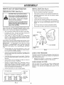
IMPORTANT:
CHECK FOR AND REMOVE ANY STAPLES
IN SKID THAT MAY PUNCTURE TIRES WHERE TRACTOR
tS TO ROLL OFF SKID:
TO ROLL TRACTOR
o
OFF SKID (See Fig. 7)
Raise attachment
lift lever to its highest position.
Release
pedal.
brake by depressing
parking
/
!
FIG. 1
Remove hex bolt, lock washer and large flat washer
from steering shaft.
clutch!brake
Place gearshift lever in neutral (N) position.
Roll tractor backwards off skid.
7
STEERINGsHAFT
/
/
///1
Ii
/
I
ASSE
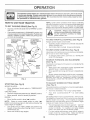
HOW TO SET UP YOUR TRACTOR
PREPARE
BATTERY
INSTALL
Adjust seat before tightening adjustment knob.
(See Fig. 2)
CAUTION: Wear eye and face shieldo
Wash hands or clothing immediately if
accidentally in contact with battery acid,
Do not smoke. Fumes from
battery acid are explosiveo
SEAT (See Fig. 3)
.
Remove cardboard packing on seat pan.
®
Place seat on seat pan and assemble shoulder bolt.
,
Assemble adjustment
Do not tighten.
Tighten shoulder bolt securely.
charged
Lower seat into operating position and sit on seat.
Slide seat until a comfortable position is reached which
allows you to press clutch/brake pedal all the way
down.
Read the instructions included with the
battery vent caps. Always wear gloves,
c_othing and goggles to protect your
hands, skin and eyes.
Get off seat without moving its adjusted position.
®
Raise seat and tighten adjustment knob securely.
Your tractor has s battery charging system which is sufficient for normal use, However, periodic charging of the
battery with an automotive charger will extend its life.
=
See instructions packed with vent caps in parts bag.
,
Fili battery with acid. Fill each cell until it reaches the
bottom of the vent wells. Do not overfill.
SEAT
SEAT PAN
SHOULDER
BOLT
Allow battery to stand and settle for at [east thirty
minutes. After standing, check the batter'.,/cell acid
level, if below the vent wells, add more acid until the
correct tevel is reached.
While battery is standing (after adding acid) and later, whiBe
batter}, is being charged, continue with assembly of tractor.
iMPORTANT:
TO MAXiMiZE
THE LiFE OF YOUR
BATTERY,
iT iS NECESSARY
THAT THE BATTERY BE
CHARGED
BEFORE
USE.
FAILURE
TO CHARGE
BATTERY
CAN RESULT iN A SHORTENED
BATTERY
L!FE.
FLAT WASHER
ADJUSTMENT
KNOB
Charge battery at a rate of 6 amperes for 1 hour. Use
a 12 volt battery charger. Observe all safety precautions required for battery charging.
,
FiG. 3
Check the acid level after the battery is charged. If the
acid has fallen below the correct level, add distilled or
iron free water.
CHECK
Check battery case for leakage to make sure that no
damage has occurred in handling.
o
Dispose of excess battery acid. Neutralize acid for
disposal by adding it to two gallons of water in a five
gallon plastic container. Stir with a wooden or plastic
paddle while adding baking soda until the addition of
more soda causes no more foaming.
,
BRAKE
SYSTEM
After you learn how to operate your tractor, check to see
that the brake is properly adjusted. See "TO ADJUST
BRAKE" in the Service and Adjustments section of this
manual.
VENT CAP
VENT
WELL
BATTERY
CELL ACID
LEVEL
FiG 2
Reduce tire pressure to PSl shown in "PRODUCT
SPECIFICATIONS" on page 3 of this manual.
CHECK
Fo!low instructions on how to install battery:
CUT AWAY VIEW
TiRE PRESSURE
The tires on your tractor were overinfiated at the factory for
shipping purposes. Correct tire pressure is important for
best cutting performance.
Install the vent caps to cover the vent wetls. Wash the
top of the battery with water to remove any acid, then
wipe dry.
o
knob and flat washer loosely.
8
ASSEMBLY
INSTALL
MOWER
o
AND DR_VE BELT
(See Figs. 4 and 7)
Be sure tractor is on levet surface. Engage parking brake.
•
Cut and remove tie down securing anti-sway bar.
Swing anti-sway bar to left side of mower deck.
•
Relieve idler tension from belt. Push idler forward and
place a block (standard wood 2 x 4 or equivalent)
behind idler pulley.
,
Slide mower under tractorwith discharge guard to right
side of tractor.
o Swing LH. gauge wheel bar forward by removing rear
retainer spring and pin.
o Install one front link in top hole of the L.H. front mower
bracket and LH. front suspension bracket. Retain with
two single loop retainer springs as shown.
,
Slide right side of mower deck forward, toward R,H.
front tire.
IMPORTANT: CHECK BELT FOR PROPER ROUTtNGIN
ALL MOWER PULLEY GROOVES. INSTALL BELT INTO
ELECTRIC CLUTCH PULLEY GROOVE.
•
o
o
-
o
•
CHECK
L,H. GAUGE
WHEELBAR
CHECK
BELTS
SUSPENSION
ARMS
PROPER
POSITION
OF ALL
FRONT
LINKS
SUSPENSION
BRACKET
_-_
S_NGLE
LOOP RETAINER
SPRINGS
3/8=16
CENTER
LOCKNUT
FRONT MOWER
BRACKET
ANTI=SWAY
BAR
/
FOR
CLUTCH
PULLEY
SHOULDER
BOLT
GAUGE
WHEEL
LEVELNESS
See the figures that are shown for replacing motion, mower
drive, and mower blade drive belts in the Service and
Adjustments section of this manual. Verify that the belts are
routed correctly.
FRONT
DOUBLE LOOP
RETAINER SPRING
(Inward pointing
deck pins)
DOUBLELOOP
RETAINER SPRING
DECK
For best cutting results, mower housing should be properly
leveled, See "TO LEVEL MOWER HOUSING" in the
Service and Adjustments section of this manual,
Install second front link in the top hole of the R.H. front
mower bracket and R.H. front suspension bracket.
Retain with two single toop retainer springs as shown.
Carefully remove block from behind idler pulley.
Turn height adjustment knob counterclockwise until it
stops.
Lower mower linkage with attachment lift lever.
CHASSIS
BRACKET
Place the suspension arms on inward pointing deck
pins. If necessary, rock and raise front of mower to
align deck pins with the holes in suspension arms,
Retain with double loop retainer springs.
Connect anti-sway bar to chassis bracket under left
footrest and retain with double loop retainer spring,
Turn height adjustment knob clockwise to remove
slack from mower suspension.
Raise deck to highest position.
Swing LH. gauge wheel bar back towards rear of
mower and secure with pin and retainer spring removed earlier,
Assemble gauge wheels as shown using long shoulder
bolts, 3/8 washers, and 3/8-16 center Iocknuts. Tighten
securelyo
Adjust gauge wheels before operating moweras shown
in the Operation section of this manual,
IDLER
PULLEY
BLOCK
(Wood2x4orequiv,)
DISCHARGE
GUARD
FIGo 4
9
BLY
INSTALL
BATTERY
(See Figs. 5 and 6)
CAUTION: Do not short battery terminalso Before installin_ battery, remove
metal bracelets,
wristwatch bands,
rings, etco
Positive terminal must be connected
first to prevent sparking from acciden=
tal grounding.
VENT
CAPS
*
Lift hood to raised position.
,
Be sure battery drain tube has not come loose and is
securely attached to drain in battery tray.
o
Lower battery into battery tray with terminals to front of
tractor.
FiG. 6
First connect RED battery cable to positive (+) battery
terminal with hex bolt, flat washer, lock washer and hex
nut as shown. Tighten securely.
o
Connect BLACK grounding cable to negative (-) battery
terminal with remaining hex bolt, flat washer, lock
washer and hex nut. Tighten securely.
,
Slide the two battery bolts through the terminal guard
and start the wing nuts onto the threads.
/ CHECKMST
BEFORE YOU OPERATE AND ENJOY YOUR NEW
TRACTOR, WE WtSH TO ASS( IRE THAT YOU RECEIVE
THE BES T PERFORMANCEAND SATISFACTION FROM
THIS QUALITY PRODUCT.
Position terminal guard over battery as shown, lower
battery bolts into key holes and slide square shafts of
battery bolts into slots of key holes.
o
PLEASE REVIEW THE FOLLOWING CHECKLIST:
Tighten wing nuts by hand making sure battery bolts
remain in s!ots of the key holes in the battery support.
Be sure terminal access doors are closed.
/
All assembly instructions have been completed.
/
No remaining toose parts in carton.
/
Batteryis properly prepared and charged.
1 hour at 6 amps).
/
Seat is adjusted comfortably and tightened securely.
•/
Alt tires are properly inflated. (For shipping purposes,
the tires were overinfiated at the factory).
,/
Be sure mower deck is properly leveled side-to-side/
front_to-rear for best cutting results. (Tires must be
properly inflated for leveling).
J
Check mower and drive belts. Be sure they are routed
properly around pulleys and inside all belt keepers.
,/
Check wiring. See that al! connections are still secure
and wires are properly clamped.
Use terminal access doors for:
,
inspection
ware)_
for secure connections
®
Inspection for corrosion.
,
Testing battery.
,
Jumping (if required).
o
Periodic charging.
(to tighten hard-
(Minimum
WHILE LEARNING HOW TO USE YOUR TRACTOR,
PA Y EXTRA A _ENTION TO THE FOLLOWING IMPORo
TANT ITEMS:
HEX
/
Engine oil is at proper level.
¢"
Fuel tank is filled with fresh, clean, regular unleaded
gasoline.
Become famitiar with alt controls - their tocation and
function. Operate them before you start the engine.
¢
/
LOCK WASHER
FroG=5
t0
Be sure brake system is in safe operating condition.
OPERATION
KNOW YOUR TRACTOR
READ THIS OWNER'S
MANUAL
AND SAFETY
RULES
BEFORE
OPERATING
YOUR TRACTOR
Compare the illustrationswith you r tractor to familiarize yourself with the locations of various controls and adjustments. Save
this manua! for future reference,
CHOKE
CONTROL
L_GHT SWITCH
LIFT LEVER
CLUTCH/BRAKE
PEDAL
THROTTLE
CONTROL
PARKING
LEVER
BRAKE
RANGE SHIFT
LEVER
HEIGHT
ADJUSTMENT
GEARSHIFT
LEVER
KNOB
"_11_
RGo 7
Our tractors conform to the safety standards of the American National Standards Institute,
ATTACHMENT CLUTCH SWITCH - Used to engage mower
blades or other attachments mounted to your tractor,
RANGE SH_FT LEVER - Allows high (H) or low (L) speed
for all forward and reverse gears.
LiFT LEVER - Used to raise and lower mower deck or other
attachments mounted to your tractor,
BGN_TtON SWITCH - Used to start and stop the engine.
CLUTCH/BRAKE
PEDAL - Used for declutching and braking the tractor and starting the engine.
(-).
GEARSHIFT
tractor.
PARKING BRAKE LEVER - Locks clutch/brake pedal into
the brake position.
THROTTLE
LEVER = Selects the speed and direction of
CONTROL
o Used to control engine speed.
AMMETER - indicates battery charging (+) or discharging
LIGHT SWITCH - Turns the headlights on and off.
CHOKE CONTROL - Used when starting a cold engine.
HEIGHT ADJUSTMENT
height.
11
KNOB - Used to adjust the mower
HOW TO USE YOUR TRACTOR
TO SET PARKING
o
BRAKE
Depress dutch/brake
and hold.
(See Fig,
NOTE: Under cedar conditions when tractor is standing
idle with the engine harming, hot engine exhaust gases may
cause "browning" of grass, To eliminate this possibility,
always stop engine when stopping tractor on grass areas.
8}
pedal into full "BRAKE" position
Place parking brake tever in "ENGAGED" position and
release pressure from clutch/brake pedal. Pedal should
remain in "BRAKE" position. Make sure parking brake
will hold vehicle secure.
PARKING BRAKE
"ENGAGED"
POSmON
_GNmON
KEY
CHOKE
CONTROL
TO USE THROTTLE
ATTACHMENT
CLUTCH SWmTCH
PULL=OUT
"ENGAGE"
CONTROL
(See Fig. 8)
Always operate engiru_,
_at fuIl throttle,
o Operating engin_:¢at less than full throttle reduces the
battery charging rate.
o Full throttle offers the best mower performance,
THROTTLE
CONTROL
LEVER
TO USE CHOKE
CONTROL
(See Fig. 8)
Use choke controi whenever you are starling a cold engine.
Do not use to stars a warm engine.
o To engage cheke control, pull knob out. Slowly push
knob in to disengage.
TO _OVE
FORWARD
AND B_tCKWARD
(See Fig° 8)
]he direction and speed of movement is controlled by the
gearshift lever_
Start tractor wth ciuteh/brake pedal depressed and
gearshift lever in neutral (N) position.
o Move gearshift and range shift Jevers to desired position.,
RANGE
SH{FT
LEVER
POSmON
"DRIVE"
POSITION
GEARSHIFT
LEVER
HEIGHT
ADJUSTMENT
KNOB
o Slowly release dutch/brake pedal to start movement.
_MPOR_°AN°[': BRING TRACTOR TO A COMPLETE STOP
BEFORE SHIFTING OR CHANGING GEARS. FAILURE
TO DO SO WiLL SHORTEN THE USEFUL LIFE OF YOUR
TRANSAXLE.
FIGo 8
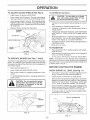
TO ADJUS°'_ _qOWER CUTtiNG
STOPPING
(See Fig, 8)
MOWER B_DES .o Move attachment
(See Fig° 8)
The cuttir_g height is controlled by turning the height adjust _
ment knob in desired direction,
o Turn knob clockwise (;-4) to _aise cutting height.
clutch switch to "DISENGAGED"
GROUND DRWE
o
o Depress clutch!brake pedal into full "BRAKE" position.
o Move gearshift _ever to neutral (N) position.
ENGINE o
o
Move throttle control to slow (_)
HEIGHT
Turn
knob counterclockwise
(V_)to
tower cutting
The cutting height range is approximately 1o4/4" to 4.-1/4",
The heights are measured from the ground to the blade tip
with the engine not ru_ning, These heights an_;,approximate and may va_ depending upon sol cor_ditions, height
of grass and _ypes of grass bei_g mowed,
o The average iawn sho_JJIdbe cut to approxin: ely 2-!/2
inches dudng the coot season and to over 3 inches
dL_ring hot months. _or healthier artd better looking
lawns mow often and after moderate growth.
For best cutting pe_'formance_ grass over 6 inches in
height shou!d be mowed twice, Make the first cut
relatively high; the secor_d to desired height°
position.
NOTE:
Failure to move throttle controJ to slow (_)
position and allowing engine to idle before stopping may
cause engine to "backfire".
Turn ignition key to "OFF" position and remove key.
AJways remove key when leaving tractor to prevent
unauthorized use.
Never use choke to stop engine.
12
OPERATION
TO ADJUST
GAUGE
WHEELS
o
*
Adjust mower to desired cutting height.
Lower mower with lift control. Remove rear retainer
spring and clevis pin which secure each gauge wheel,
,
Lower gauge wheels to ground. Raise gauge wheels
slightly to align holes in bracket and gauge wheel bar
and insert clevis pins. Gauge wheels should be slightly
off the ground.
*
TO OPERATE
(See Fig. 9)
,
RETAINER
CLEVIS
Choose the slowest speed before starting up or down
hills.
Avoid stopping or changing speed on hills.
If slowing is necessary, move throttle control lever to
slower position.
If stopping is absolutely necessary, push clutch/brake
pedal quickly to brake position and engage parking
brake.
Replace retainer springs into clevis pins.
SPRING
ON HILLS
"_-_
PiN
Move gearshift lever to 1st gear and range shift lever to
low (L) position. Be sure you have allowed room for
tractor to roll slightly as you restart movement.
To restart movement, slowly release parking brake and
clutch/brake pedal.
Make all turns slowly.
TO TRANSPORT
WHEEL
,
TO OPERATE
MOWER
Your tractor is equipped with an operator presence sensing
switch. Any attempt by the operator to leave the seat with
the engine running and the attachment clutch engaged wilt
shut off the engine.
Select desired height of cut.
Lower mower with attachment lift control.
,
Start mower blades by engaging attachment
control.
lift to highest position with attach-
When pushing or towing your tractor, be sure gearshift
lever is in neutral (N) position.
o Do not push or tow tractor at more than five (5) MPH.
NOTE: To protect hood from damage when transporting
your tractor on a truck or a trailer, be sure hood is closed and
secured to tractor. Use an appropriate means of tying hood
to tractor (rope, cord, etc.).
(See Figs. 7 and 8)
o
.
Raise attachment
ment lift control.
BEFORE STARTING
CHECK
ENGINE
THE ENGINE
OiL LEVEL
(See Fig. 11)
clutch
•
The engine in your tractor has been shipped, from the
factory, already filled with summer weight oil.
TO STOP MOWER BLADES - disengage attachment
clutch control.
o
Check engine oil with tractor on level ground.
,
Remove oil fill cap/dipstick and wipe clean, reinsert the
dipstick and screw cap tight, wait for a few seconds,
remove and read oil level. If necessary, add oil until
"FULL" mark on dipstick is reached. Do not overfill.
•
For cold weather operation you should change oil for
easier starting (_ee OIL VISCOSITY CHART in the
Customer Responsibilities section of this manual).
o
To change engine oil, see the Customer Responsibilities section in this manual.
CAUTION: Do not operate the mower
without either the entire grass catcher,
on mowers so equipped, or the discharge guard in place.
OiL FILL CAPtDIPSTtCK
D}SCHARGE
GUARD
FIGo 10
FIG. 11
13
ADD
GASOUNE
MOWING T PS
Fill fuei tank.
Use fresh, clean, regular unleaded
gasoline. (Use of leaded gasoline will increase carbon
and lead oxide deposits and reduce valve life).
_MPORTANT: WHEN OPERATING {N TEMPERATURES
BELOW 32°F(0°C), USE FRESH, CLEAN WINTER GRADE
GASOLINE TO HELP INSURE GOOD COLD WEATHER
STARTING.
WARNING:
Experience indicates that alcohol blended
fuels (called gasohol or using ethanol or methanol) can
attract moisture which leads to separation and formation of
acids during storage. Acidic gas can damage the fuel
system of an engine while in storage. To avoid engine
problems, the fuel system should be emptied before storage of 30 days or longer. Drain the gas tank, start the
engine and let it run until the fuel lines and carburetor are
empty. Use fresh fuel next season. See Storage Instructions for additional information.
Never use engine or
carburetor cleaner products in the fuel tank or permanent
damage may occur.
CAUTION:
FiW_to
filler neck. Do not
spilled oil or fuel.
use gasoline near
TO START
ENGINE
bottom of gas tank
overfill Wipe off any
Do not store, spill or
an open flame°
o
Tire chains cannot be used when the mower housing is
attached to tractor.
o
Mower should be properly leveled for best mowing
performance. See "TO LEVEL MOWER HOUSING" in
the Sewice and Adiustments section of this manual.
o
Use the runner on the right hand side of mower as a
guide. The blade cuts approximately an inch outside
the runner (See Fig. 10).
The left hand side of mower should be used for trim°
min%
o
o
When mowing large areas, start by turning te the right
so that clippings will discharge away frb_ shrubs,
fences, driveways, etc. After one or two rOahds, mow
in the opposite direction making left hand turns untii
finished (See Fig. t2).
o
If grass is extremely tall, it should be mowed twice to
reduce load and possible fire hazard from dried clippings. Make first cut relatively high; the second to the
desired height.
o
Do not mow grass when it is weL Wet grass will plug
mower and Ieave undesiraMe dumps. Altow grass to
dry before mowing.
(See Fig° 8)
When starting engine for the first time or if engine has run
out of fuel, it will take extra cranking time to move fuel from
the tank to the engine.
o
AIways operate engine at full throttle when mowing to
assure better mowing pe#ormance and proper discharge of material. Regulate ground speed by selecting a low enough gear to give the mower cutting
pedormance as wel! as the quality of cut desired.
Depress clutch!brake pedal and set parking brake.
Place gearshift lever in neutral (N) position.
,
Move attachment clutch to "DISENGAGED"
position.
o
PuN choke control out to choke (tXt) position for cold
engine start. For warm engine start do not use choke
contro!.
Drive so that clippings are discharged onto the area
that has been cut. Have the cut area to the right of the
machine. This will result in a more even distribution of
clippings and more uniform cutting.
o
When operating attachments, select a ground speed
that wil! suit the terrain and give best performance of
the attachment being used.
Move throttte control to midway between fast (@) and
stow (_) positions.
_nsertkey into ignitionand tum key c!ockwise to "START"
position and release key as soon as engine starts. Do
not run starter continuously for more than fifteen
seconds per minute. If engine does not start after
several attempts, move throttle control to fast (@)
position, wait a few minutes and try again.
o
-
When engine starts, slowly push choke control in.
Move throttle contro! to fast (4)
position.
Allow engine to warm up for a few minutes before
engaging drive or attachments.
NOTE: If at a high altitude (above 3000 feet) or in cold
_emperatures {below 32°F), the carburetor fuet mixture
may need to be adjusted for best engine pedormance. See
"TO ADJUST CARBURETOR" in the Service and Adjustmen_s section of this manual.
F_G, ! 2
_'_7.J,._,
"_#d.,._,
"_S
TI_oF_oo,-s
JI
J
J
i
Ir, J
I
_.l
JJ
.... t-- ---PK-4-......
__J
--
. 4F___ ....
J
±_
____p ....
I
I
_,./
__1 ___L_J.....
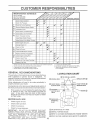
1 - Change more often when operating under a heavy load or in high ambient temperatures.
2 - Service more often when operating in dirby or dusty conditions.
3 - If equipped with oil filter, change oil every 50 hours.
4 - Replace
GENERAL
blades
more often
when
mowing
in sandy
soil,
_±__
5 - If equipped with adjustable system.
6 - Not required if equipped with maintenance4ree battery.
7 - Tighten front axle pivot bolt to 35 ft.dbs maximum.
Do not overtighten.
RECOMMENDATIONS
LUBRICATION
The warranty on this tractor does not cover items that have
been subjected to operator abuse or negligence.
To
receive full value from the warranty, operator must maintain
tractor as instructed in this manuak
Some adjustments will need to be made periodically to
propedy maintain your tractor.
(_TIE
Q
All adjustments in the Service and Adjustments section of
this manual should be checked at least once each season.
Once a year you should replace the spark plug, clean
or replace air filter, and check blades and belts for
wear. A new spark plug and clean air filter assure
proper air-fuel mixture and help your engine run better
and last longer.
BEFORE
EACH
USE
CHART
ROD BALL JOINTS
FRONT WHEEL
FRONT WHEEL O
BEARING
BEAR,NG
ZER__==_VL__
@STEERJ.G,
ZERK
-_%;_
SECTOR GEAR
ENGINE (_)
TEETH
@
TRANSAXLE
•
"
Check engine oillevel,
Check brake operation,
FLUID
Check tirepressure,
Check forloosefasteners.
_MPORTANT:
DO NOT OIL OR GREASE THE PIVOT
POINTS WHICH HAVE SPECIAL NYLON BEARINGS.
VISCOUS LUBRICANTS WiLL ATTRACT DUST AND DIRT
THAT WiLL SHORTEN THE LIFE OF THE SELFLUBRICATING BEARINGS, IF YOU FEEL THEY MUST
BE LUBRICATED,
USE ONLY A DRY, POWDERED
GRAPHITE TYPE LUBRICANT SPARINGLY_
!_
_SAE
30 _IOTOR OIL AP[ o SF/SG
(_ GENERAL
PURPOSE
GREASE
@ REFER TO CUSTOMER
@SPRAY
S[BCONE
RESPONS[BJUTIES
LUBRICANT
"ENGINE"
SECTION
(B'JOVE BOOTS TO LUBRICATE)
C
TRACTOR
o
Always observe safety rules when performing any maintenance.
The blade can be sharpened with a file or on a grinding
wheel. Do not attempt to sharpen while on the mower.
®
To check blade balance, you will need a 5/8" diameter
steel bolt, pin, ora cone balancer. (When using a cone
balancer, follow the instructions supplied with bai-
BRAKE
OPERATION
ancBr).
If tractor requires more than six (6) feet stopping distance
at high speed in highest gear, then brake must be adjusted.
(See "TO ADJUST BRAKE" in the Service and Adjustments section of this manual).
o
TIRES
-
Slide blade on to an unthreaded portion of the steel bolt
or pin and hold the bolt or pin parallel with the ground.
if btade is balanced, it should remain in a horizontal
position, If either end of the blade moves downward,
sharpen the heavy end until the blade is balanced.
NOTE: Do not use a nail for balancing blade. The lobes of
the center hole may appear to be centered, but are not.
Maintain proper air pressure in all tires (See "PRODUCT SPECIFICATIONS" on page 3 of this manual).
Keep tires free of gasoline, oil, or insect control chemicals which can harm rubber.
,
Avoid stumps, stones, deep ruts, sharp objects and
other hazards that may cause tire damage.
BLADE
CARE
For best results mower blades must be kept sharp.
place bent or damaged blades.
BLADE
-
REMOVAL
Re-
(See Fig. 13)
Raise mower to highest position to allow access to
blades.
F_G. 14
Remove hex bolt, lock washer and flat washer securing
blade.
V_BELTS
Install new or resharpened blade with trailing edge up
towards deck as shown.
Check V-belts for deterioration and wear after 100 hours
and replace if necessary. The belts are not adjustable.
Replace belts if they begin to slip from wear.
Reassemble hex bolt, lock washer and fiat washer in
exact order as shown.
TRANSAXLE
Tighten bolt securely (30-35 Ft. Lbs. torque).
_MPORTANT: BLADE BOLT iS GRADE 8 HEATTREATED.
COOMNG
Keep transaxle free from build-up of dirt and chaff which
can restrict cooting
NOTE: We do not recommend sharpening blade _but if you
do, be sure the blade is balanced.
CHECK
TRANSAXLE
OIL LEVEL
(See Fig. 15)
MANDREL
ASSEMBLY
BLADE
Block up rear axle securely or use a tractor jack.
Remove left rear whee! by removing hub bolts.
,
TRAILING
EDGE UP
o
Remove filler plug from transaxle. Oil level must be
even with pIug threads. If necessary, fill with SAE 30
motor oil, Ap!oSF or SG. Replace filler plug.
Reassemble wheel to hub.
For approximate capacity see "PRODUCT
CATIONS" on page 3 of this manuat.
BE× BOLT (GRADE 8)'-_,,_
TRANSAXLE
PLUG
*A GRADE 8 HEAT TREATED BOLT CAN BE
iDENTIFIED BY SiX LINES ON THE BOLT HEAD,
FIG. 13
TO SHARPEN
BLADE
SPECIFI-
(See Fig. 14)
Care should be taken to keep tile blade balanced. An
unbalanced blade will cause excessive vibration and eventual damage to mower and engine.
F_Go 15
16
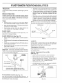
CUSTO
(See Fig. 16}
BATTERY
Your tractor
has a batterychargingsystem which issufficientfornormal use. However, periodicchargingofthe
batten/, with an automotive charger wil! extend its life.
Acid solution bvel in each battery celi should be even
with bottoms of vent wells. Add only distilled or iron free
water if necessary. Do not overfill
Change the oil after the first two hours of operation and
every 25 hours thereafter or at least once a year if the
tractor is not used for 25 hours in one year.
Keep battery and terminals clean.
Check the crankcase oil level before starting the engine
and after each eight (8) hours of operation. Tighten oil fill
cap/dipstick securely each time you check the oil level.
Keep battery bolts tight.
o
Keep vent caps tight and small vent holes in caps open.
*
Recharge at 6 amperes for 1 hour.
TO CLEAN BATTERY AND TERMINALS
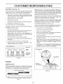
TO CHANGE ENGINE OIL (See Fig. 18)
-
Determine temperature range expected before oil change,
Att oit must meet API service classification SF or SG.
Corrosion and dirt on the battery and terminals can cause
the batter`i to "leak" power,
Be sure tractor is on level surface.
Remove terminal guard.
®
o
Disconnect BLACK battery, cable first then RED battery cable and remove battery from tractor.
,
Wash battery with solution of four tablespoons of
baking soda to one gallon of water. Be careful Rot to get
the soda solution into the cells.
o
NOTE: Although multi-viscosity oils (5W30, 10W30 etc,)
improve starting in cold weather, these multi-viscosity oils
will result in increased oil consumption when used above
32°F, Check your engine oil bve! more frequently to avoid
possible engine damage from running low on oil,
Remove oil fill cap/dipstick. Be careful not to allow dirt
to enter the engine when changing oil.
Remove drain plug.
After oil has drained completely, replace oil drain plug
and tighten securely.
Rinse the battery with plain water and dr'i.
Clean terminals and batten/cable ends with wire brush
until bright.
,
Refill engine with oil through oil fill dipstick tube. Pour
slowly. Do not overfill. For approximate capacity see
"PRODUCT SPECIFICATIONS"
on page 3 of this
manual
Coat terminals with grease or petroleum jelly.
Reinstall battery (See "INSTALL BATTERY"
Assembly section of this manual),
Oil will drain more freely when warm.
Catch oit in a suitable container,
in the
o
CUT AWAY VIEW
Use gauge on oil fill cap/dipstick for checking level, Be
sure dipstick cap is tightened securely for accurate
reading. Keep oil at "FULL" line on dipstick.
BATTERY
CELL ACID
WELL
LEVEL
AiR SCREEN
FiG. 16
/
ENGINE
LUBRBCATION
Only use high quality detergent oil rated with API sewice
c lassification S F or SG. Select the oil's SAE viscosity grade
according to your expected operating temperature.
--
SAE VISCOSITY GRADES
°F
o_
-20 °
.30_
0o
-20 °
TEMPERATURE
30 _
ol _
RANGE
32 °
40 °
0°
ANTiCiPATED
FiG. t 8
60 _
10°
BEFORE
80 °
20 °
NEXT
100 °
30 °
40°
OIL CHANGE
FIG. 17
t7
E8
ER
CLEAN
(See Fig. 18)
AMR SCREEN
Air screen must be kept free of dirt and chaff to prevent
engine damage from overheating. Clean with a wire brush
or compressed air to remove dirt and stubborn dried gum
fibers.
ENGBNE COOUNG
FiNS (See Fig. 19)
FOAM
PRE-CLEANER
Remove any dust, dirt or oil from engine cooling fins to
prevent engine damage from overheating. Engine blower
housing must be removed. Remove side panels and hood
(See "TO REMOVE HOOD AN D G RILL ASSEMBLY" in the
Service and Adjustments section of this manual).
CARTRIDGE
A_R SCREEN
F_G 20
Inspect and replace corroded muffler and spark arrester (if
equipped) as it could create a fire hazard and/or damage.
SPARK
AIR GUIDE
COVER
(BOTH S_DES)
Replace spark [;,lugs at the be_{_inning of each mowing
season or after every 100 hours of operation, whichever
comes first. Spark ptug type and gap setting are shown in
"PRODUCT SPECIFICATIONS" on page 3 of this manuak
,_
FiG. 19
IN-UNE
AiR FILTER
(See Fig, 20)
Service air cleaner more often under dusty conditions.
Remove knob(s) and cover.
TO SERVICE PRE-CLEANER
o
o
FUEL FH.TER
(See Fig° 21)
The fuel filter should be replaced once each season. _ffuel
filter becomes clogged, obstructing fuel flow to carburetor,
replacement is required.
o With engine cool, rerrlove filter and plug fuel line
sections.
o Place new fuel filter in position in fuel tine with arrow
pointing towards carburetor.
o Be sure there are no fuel line leaks and clamps are
Your engine will not run properly using a dirty air filter.
Clean the foam pre-cleaner after every 25 hours of opera-.
tion or every season. Sen,ice paper cartridge every 100
hours of operation or every season, whichever occurs first.
o
o
PLUGS
Slide foam pre=cleaner off cartridge.
Wash it in liquid detergent and water.
Squeeze it dry in a clean cloth.
Saturate it in engine oil. Wrap it in clean, absorbent
cIoth and squeeze to remove excess oil.
If very, dirly or damaged, replace preocleaner.
Reinsta!l pre-cleaner over cartndgeo
Reinstal! cover and secure with knob(s).
o
Immediately wipe up any spiiled gasoline.
CLAMP
FUEL FnLTER
TO SERVICE CARTRIDGE
Remove wing nuts and cartridge plate.
Carefully remove cartridge to prevent debris from en°
tering carburetor°
Clean cartridge by tapping gentty on flat surface. Ifvery
dirty or damaged, replace cartridge.
o
Reinstall cartridge plate, wing nuts, precleaner, cover
and secure with knob(s).
BMPORTANT:
PETROLEUM SOLVENTS, SUCH AS
KEROSENE, ARE NOT TO BE USED TO CLEAN THE
CARTRDGE.
THEY MAY CAUSE DETERIORAT!ON OF
THECARTRDGE.
DO NOT OtLCARTRDGE.
DO NOT
USE PRESSURIZED
AIR TO CLEAN OR DRY
CARTRIDGE.
HGo 21
o
o
o
CIean engine,battery, seat, finish, etc. of all foreign
matter.
o
Keep f nished surtaces and wheels free of a, gasoline,
oi!, etc.
Protect painted surfaces with automotive type wax.
18
We do not recommend using a garden hose to clean your
tractor uniess the electrical system, muffler, air filter and
carburetor are cove_ed to keep water out° Water in engine
can result in a shc _ened e,qg ne life.
E
CAUT|ON:
,
,
®
o
ADJUSTMENTS
BEFORE PERFORMING
ANY SERVICE OR ADJUSTMENTS:
Depress dutebJbrake pedamfully and set parking brake.
P_ace gearshift _ever in neutral (N) position.
Place attachment c_utch in "DISENGAGED"
position.
Turn ignition key "OFF" and remove key.
Make sure the bUades and aRImoving parts have completely stopped.
Disconnect spark ptug wire from spark plug and p_ace wire where it cannot come in contact
with plug.
TRACTOR
TO REMOVE
TO LEVEL
MOWER
(See Fig° 22)
,
Place attachment clutch in "DISENGAGED" position
Turn height adjustment knob to lowest setting.
Lower mower to its lowest position.
,
Remove retainer spring holding anti-swaybar to chassis bracket and disengage anti-swaybar from bracket.
,
Remove retainer springs from suspension arms at
deck and disengage arms from deck.
o Raise attachment lift to its highest position.
,
Remove two retainer springs from each front link and
remove links.
,
Slide mower forward and remove belt from electric
clutch pulley.
*
Slide mower out from under right side of tractor.
_MPORTANT: IF AN ATTACHMENT OTHER THAN THE
MOWER DECK IS TO BE MOUNTED ON ]"HE TRACTOR,
REMOVE THE FRONT LINKS.
TO INSTALL
MOWER
HOUSING
Adjust the mower while tractor is parked on level ground or
driveway.
Make sure tires are properly inflated (See
"PRODUCT SPECIFICATIONS" on page 3 of this manual).
If tires are over or underinflated, you will not properly adjust
your mower.
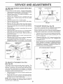
SIDE°TO-SIDE ADJUSTMENT (See Figs. 22 and 23)
o Raise mower to its highest position.
o Measure height from bottom of deck curl to ground
level at front corners of mower. Distance "A" should be
the same.
If distance "A" needs to be changed, make adjustment
on one side of mower only.
Raise one side of mower by tightening lift link adjustment nut on that side.
o
Lower one side of mower by loosening lift link adjustment nut on that side.
NOTE: Each half turn of adjustment nut will change deck
{evet about 3,/t 6"
o
MOWER
Recheck level after adjusting.
BOTTOM
OF CURL
Follow procedure described in "INSTALL MOWER AND
DRIVE BELT" in the Assembly section of this manual.
BOTTOM
OF CURL
FRONT
SUSPENS|ON
ADJUSTMENT
SUSPENSION
ARMS
NUTS
BRACKET
L_
LINKS
GROUND L|NE
_'\.
-\
FiG. 23
FRONT MOWER
BRACKET
CHASSIS
BRACKET
CLUTCH
PULLEY
'FRONT
SUSPENSION
BRACKET
RETAINER
SPRINGS
RETAINER
SPRING
MOWER
BRACKET
\
ANT_-SWAY
BAR
RETAINER
SPRINGS
19
SERVICE
AN
A
TO REPLACE
FRONT-TO-BACK ADJUSTMENT (See Figs. 24 and 25) IMPORTANT: DECK MUST BE LEVEL SIDE-TO=SIDE. IF
THE FOLLOWING FRONT-TO-BACK ADJUSTMENT IS
NECESSARY, BE SURE TO ADJUST BOTH FRONT LINKS
EQUALLY SO MOWER WILL STAY LEVEL SlDE-TO-SlDE.
To obtain the best cutting results, the mower housing
should be adjusted so the front is approximately 1/8" to 1/2"
lower than the rear when the mower is in its highest
position.
Check adjustment on right side of tractor. Measure distance "F" directly in front of and behind the mandrel at
bottom edge of mower housing as shown.
o Before making any necessary adjustments, check that
both front links are equal in length.
If links are not equal in length, adjust one link to same
length as other link.
To lower front of mower housing, loosen nut"G" on both
front links an equal number of turns.
o When distance "F" is 1/8" to 1/2" lower at front than
rear, tighten nut"H"against trunnion on both front link&
,
To raise front of mower housing, loosen nut "H" from
trunnion on both front links. Tighten nut "G" on both
front links an equat number of turns.
o When distance "F" is 1/8" to 1/2" lower at front than
rear, tighten nut "H" against trunnion on both front
Hnks_
NOTE,: Each furl turn of nut "G" win change dim. "F" by
approximately 3/8"'.
o Recheck side-to-side adjustment.
MOWER
DRt_VE BELT
MOWER DRIVE BELT REMOVAL (See Fig. 26) =
o Park tractor on a ieve! surface. Engage parking brake.
,, Remove four screws from L.H. mandrel cover and
remove cover.
o
Roll belt over the top of L,H. mandrel pulley,
o
Remove belt from electric clutch pultey.
o
Remove belt from idler pulleyso
Remove any di_ or grass clippings which may have
accumulated around mandrets and entire upper deck
surface.
o
Check primary idler arm and two idlers to see that they
rotate freely.
o
Be sure spring is securely hooked to primary idler arm
and bolt in mower housing.
MOWER DRWE BELT _NSTALLAT_ON (See Fig. 26) o _nstall belt in both idlerso Make sure belt is in both belt
keepers at the idlers as shown.
Instal! new belt onto electric clutch pulley.
o
Roll belt into upper groove of L.Ho mandrel pulley.
Carefully check belt routing making sure belt is in the
grooves correctly and inside belt keepers.
Reassemble L.H. mandre_ cover.
SPR_NG
LoB,
MANDREL
MANDREL
COVER
SCREWS
_DLER
PULLEYS
PRIMARY
_DLER ARM
FJGo24
BOTH FRONT LINKS SHOULD
BE EQUAL iN LENGTH
F_Go26
RG° 25
20
ELECTRIC
CLUTCH
PULLEY
SE
TO REPLACE
(See Fig, 27)
MOWER
CE AND ADJ
BLADE
DRIVE
BELT
ROTOR
Park the tractor on level surface. Engage parking brake.
Remove mowerdrive belt (Bee"TO REPLACE MOWER
DRIVE BELT" in this section of this manual).
Remove mower (See "TO REMOVE MOWER" in this
section of this manual).
Remove four screws from R.H. mandrel cover and
remove cover. Unhook spring from bolt on mower
housing.
°
Carefully roll belt off R.H. mandrel pulley.
o
Remove belt from center mandrel pulley, idler pulley,
and L.H. mandrel pulley.
Remove any dirt or grass which may have accumu..
tated around mandrels and entire upper deck surface.
Check secondary idler arm and idler to see that they
rotate freely.
,
Be sure spring is hooked in secondary idler arm and
sway-bar bracket.
Install new belt in lower groove of hR. mandrel pulley,
idler pulley, and center mandrel pulley as shown.
Roll belt over R.H. mandrel pulley. Make sure belt is in
all grooves properly.
Reconnect spring to bolt in mower housing and reinstall R.H. mandrel cover.
Reinstall mower to tractor (See"TO INSTALL MOWER"
in the Assembly section of this manual).
,
Reassemble mower drive belt (See "TO REPLACE
MOWER DRIVE BELT" in this section of this manual).
L.H.
MOWER BLADE
DRIVE BELT
;TlViENTS
CLUTCH
PLATE
BRAKE
PLATE
BLOT(3)
FIGo28
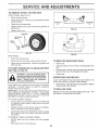
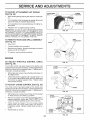
TO ADJUST
BRAKE
(See Fig. 29)
Your tractor Js equipped with an adjustable brake system
which is mounted on the left side of the transaxte.
If tractor requires more than six (6) feet stopping distance
at high speed in highest gear, then brake must be adjusted.
o
Depress clutch/brake pedal and engage parking brake.
Measure distance between brake operating arm and
nut "A" on brake rod.
If distance is other than 1 o3/4", loosen jam nut and turn
nut "A" until distance becomes 1-3/4". Retighten jam
nut against nut "A".
Road test tractor for proper stopping distance as stated
above. Readjust if necessary. If stopping distance is
still greater than six (6) feet in highest gear, further
maintenance is necessary. Contact your nearest authorized service center/department.
CENTER
WITH PARKING BRAKE "ENGAGED"
SECONDARY
IDLER ARM
NUT "A"
SPRING
/
SWAY-BAR
BRACKET
OPERATING
ARM
FIGo 27
TO ADJUST
ATTACHMENT
JAM NUT
CLUTCH
(See Fig. 28)
The electric clutch should provide years of service. The
clutch has a builtdn brake that stops the pulley within 5
seconds. Eventually, the internal brake will wear which
may cause the mower blades to not engage, or, to not stop
as required. Adjustments should be made by your nearest
authorized service center/department.
Make sure attachment clutch and ignition switches are
in "OFF" position.
,
Adjust the three nylon Iocknuts until space between
clutch plate and rotor measures ,012" at all three slot
locations cut in the side of brake plate.
NOTE: After installing a new electric clutch, run tractor at
full throttle and engage and disengage electric clutch 10
cycles to wear in clutch plate.
FiG. 29
21
ADJU
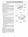
TO REPLACE
(See Fig. 30)
MOTION
DRIVE BELT
TO ADJUST
FRONT WHEEL
Remove mower drive belt from electric clutch pulley
only (See "TO REPLACE MOWER DRIVE BELT" in
this section of this manual).
Roll belt off clutching idler pulleys, then off engine
pulley and front V-idler pulley.
o
,
Place V part of belt into grooves on engine pulley and
front V-idler, making sure to route belt inside of belt
keepers.
,
Put belt coming from V-idler above midspan belt keeper,
then onto clutching idler pulleys as shown.
,
Make sure "V" part of belt engages "V" idler.
•
Place belt around transaxle pulley, beginning at top.
"V" part of belt should engage transaxle pulley.
,
Place long lower section of belt through loop in midspan
belt keeper.
,
Check to be sure belt is on proper side of all belt
keepers.
TOE4N
ADJUSTMENT
TO CHECK TOE-IN (See Fig. 31) -
•
Pull belt out of all belt keepers.
BELT INSTALLATION ,
ALIGNMENT
Front wheel toe-in is required for proper steering operation.
Toe-in was set at the factor,i and adjustment should not be
necessary. If parts in the front axle or steering mechanism
have been replaced or damaged, check toe-in and adjust
if necessary.
,, Roll motion drive belt off transaxte pulley.
,
WHEEL
If steering wheel crossbars are not horizontal (left to right)
when wheels are positioned straig ht forward, remove steering wheel and reassemble per instructions in the Assembly
section of this manual.
Park the tractor on level surface. Engage parking brake.
For ease of service there isa belt installation guide decat on
bottom of left footrest. It is not necessary to remove mower.
BELT REMOVAL ,
STEERING
Position front wheels straight ahead.
Measure distance between wheels at front and rear of
tires (dimensions "A" and "B").
Front dimension "A" should be 1/8" to 1/4" less than
rear dimension "B".
TO ADJUST TOE-IN (See Figs. 31 and 32) o
Loosen jam nuts at adjustment sleeves on tie rod.
Adjust tie rod until dimension "A" is 1/8" to 1/4" less than
dimension "B".
Tighten jam nuts securely.
B
,
Reinstall mower drive belt onto electric clutch pulley.
IMPORTANT: CHECK BRAKE ADJUSTMENT.
TRACTOR V-BELT DRIVE SCHEMATIC
VIEWED FROM LH° SIDE OF TRACTOR
CLUTCHING
IDLER
CLUTCHING
FLAT IDLER
FRONT OF TRACTOR
A
BELT
t KEEPER
_
FIG° 3!
ENGINE
PULLEY
ADJUSTMENT SLEEVES
V-IDLER
KEEPI
BELT
TWISTS
BELT
KEEPER
PULLEY
TRANSAXLE
PULLEY
JAM NUTS
FIG° 32
AS VIEWED FROM BOTTOr,_
FRONT
FiG, 30
WHEEL
CAMBER
The front wheel camber is not adjustable on your tractor. If
damage has occurred to affect the front wheel camber,
contact your nearest authorized service center/department.
22
ADJUSTMENTS
TO REMOVE
WHEEL
FOR REPAIRS
FRONT WHEEL (See Fig. 33)
-
Block up axte securely.
Remove axle cover, retaining ring and washers to allow
wheel removal.
Repair tire and reassemble.
Replace washers and snap retaining ring securely in
axle groove.
o
Replace axle cover.
WASHERS
RETA_NING
PANEL
BOLT
AXLE
COVER
FiG. 33
FIGo 35
REAR WHEEL Block rear axle securely.
o
Remove five (5) hub bolts to allow wheel removal.
TO REPLACE
Repair tire and reassemble.
bolts securely.
,
Replace and tighten hub
TO START ENGINE WiTH A WEAK
'See Figs. 34 and 35)
CAUTnON:
gener-
INTERLOCKS
AND RELAYS
Loose or damaged wiring may cause your tractor to run
poorly, stop running, or prevent it from starting.
o
If your battery is too weak to start the engine, it should be
recharged,
if "jumper cables" are used for emergency
starting, follow this procedure:
Check wiring. See electrical wiring diagram in Repair
Parts section of this manual.
TO REPLACE
_MPORTANT:
YOUR TRACTOR IS EQUIPPED WITH A 12
VOLT NEGAT{VE
GROUNDED
SYSTEM.
THE OTHER
VEHICLE
MUST
ALSO
BE A 12 VOLT
NEGATIVE
GROUNDED
SYSTEM.
DO NOT USE YOUR TRACTOR
BATTERY TO START OTHER VEHICLES.
FUSE
Replace with 30 amp automotive-type plug-in fuse.
fuse holder is located behind the dash.
CABLES o
Connect each end of the RED cable to the POSITIVE
(+) terminal of each battery,, taking care not to short
against chassis.
Connect one end of the BLACK cable to the NEGATIVE (-) terminal of fully charged battery.
,
Raise hood.
Replace bulb in holder and push bulb holder securely
back into the hole in the backside of the grill.
Close hood.
and smoking materials away from batate explosive gases. Keep sparks, flame
teries.
Always wear eye protection
when around batteries.
TO ATTACH JUMPER
BULB
Pull bulb holder out of the hole in the backside of the
grill.
BATTERY
Lead-acid batteries
HEADMGHT
Connect the other end of the BLACK cable to a panel
bolt on the left side of the tractor, away from fuel tank
and battery.
TO REMOVE CABLES, REVERSE ORDER o
BLACK cable first from chassis and fully charged
battery
RED cable last from both batteries.
23
The
SERVICE
TO ADJUST ATTACHMENT
(See Fig. 36)
ADJUSTMENTS
LiFT SPRING
ADJUSTMENT
=
While holding spring bushing with wrench, loosen jam
nut.
=
Turn adjustment bolt clockwise to extend spring and
reduce tift effort (for heavier attachments).
-
Turn adjustment bolt counterclockwise
tachments.
SPRING
for lighter at-
JAM NUT
,
Retighten jam nut against spring bushing.
IMPORTANT:
DO NOT ADJUST FOR MAXIMUM SPRING
TENSION WHEN USING LIGHT ATTACHMENTS
SUCH
AS A MOWER.
ADJUST LIFT LEVER SPRING TO AID IN
LIFTING ATTACHMENT.
DO NOT OVERPOWER
SPRING.
WHEN REMOVING
ATTACHMENT,
ALWAYS
ADJUST
SPRING TENSION TO ITS. LOWEST POSITION.
TO REr,,_IOVE HOOD
AND
GRILL
ATTACHMENT
LiFT SPRING
®
o
®
FiG. 36
WiRE
CONNECTION
ASSEMBLY
(See Fig. 37}
,
Raise hood.
,
Unsnap headlight wire connector.
Stand in front oftractor. Grasp hood at sides, tilt toward
engine and lift off of tractor.
To replace, reverse above procedure.
ENGINE
TO ADJUST
THROTTLE
(See Fig. 38)
CONTROL
CABLE
FIG, 37
The throttle control has been preset at the factory and
adjustment should notbe necessary. Checkadjustment as
described below before loosening cable. If adjustment is
necessary, proceed as follows:
,
With engine not running, move throttle control lever to
fast (,_) position.
-
Check that swivel is against side of quarter circle. If it
is not, loosen cable clamp screw and pull cable back
until swivel is against quarter circle. Tighten cable
clamp screw securely.
TO ADJUST
CHOKE
CONTROL
CLAMP
SCREW
(See Fig. 39)
The choke control has been preset at the factory and
adjustment should not be necessary. Check adjustment as
described below before loosening cable, if adjustment is
necessary, proceed as follows:
SWIVEL
F_G°38
With engine not running, move choke controt (located
on dash panel) to full choke (N) position.
*
,
CHOKE
Remove air cleaner cover, filter and cartridge plate to
expose carburetor choke (see "AIR FILTER" in the
Customer Responsibilities section of this manual).
Choke should be closed. If it is not, loosen casing
clamp screw and move choke cable until choke is
completeJy closed. Tighten casing damp screw set,
curely.
Reassemble air cteaner.
CLOSED_
CAS,NG
_
CLAMP
_
SCREW
24
_
.
' _
]
,
_\_
F_Go39
CHOKE
LEVER
E
ADJUSTMENTS
TO ADJUST CARBURETOR
(See Figs. 40 & 41)
iDLE SPEED
SCREW
The carburetor has been preset at the factory and adjustment should not be necessary. However, minor adjustment may be required to compensate for differences in fuel,
temperature, altitude or load. If the carburetor does need
adjustment, proceed as follows:
iDLE MIXTURE
SCREW
in general, turning the mixture screw in (clockwise) decreases the supply of fuel to the engine giving a leaner fuel/
air mixture. Turning the mixture screw out (counterclockwise) increases the supply of fuel to the engine giving a
richer fuel!air mixture.
IMPORTANT:
DAMAGE
SEATS IN CARBURETOR
TURNED tN TOO TIGHT.
PRELIMINARY
THROTTLE
LEVER
TO THE NEEDLES AND THE
MAY RESULT iF SCREW IS
SETTING =
-
Be sure you have a clean air filter, and the throttle
control cable and choke are adjusted properly (see
above).
•
With engine off turn idle mixture screw in (clockwise)
closing it finger tight and then turn out (counterclockwise) 1-.1/4 to 1-1/2 turns.
FIG. 40
IDLESPEED
__(,
'_
FINAL SETTING o
Start engine and allow to warm for five minutes. Make
final adjustments with engine running and shift/motion
control lever in neutral (N) position.
With throttle controt lever in slow (_)
position, hold
throttle lever against idle speed screw and adjust idle
speed screw to obtain 1200 to 1400 RPM.
SCREW
While still holding throttle lever against idle speed
screw, turn idle mixture screw in (clockwise) until
engine begins to die and then turn out (counterclockwise) until engine runs rough. Turn screw to a point
midway between those two positions.
®
o
Move throttle control lever from stow (,_!,) to fast (,t_)
position.
If engine hesitates or dies, turn idle mixture
screw out (counterclockwise)
1/8 turn.
Repeat test
and continue to adjust, if necessary,
until engine accelerates smoothly.
adjusted.
Do not adjust
E MIXTURE
SCREW
F|G. 4t
TEST-
High speed stop is factor},
damage may result.
)_
THRO
LEVER
Continue to hold throttle lever against idle speed screw
and adjust idle speed screw to obtain 900 to 1200 RPM.
Release throttle tever.
ACCELERATION
__
-
IMPORTANT:
NEVER
TAMPER
WITH THE ENGINE
GOVERNOR,
WHICH IS FACTORY
SET FOR PROPER
ENGINE SPEED. OVERSPEEDING
THE ENGINE ABOVE
THE
FACTORY
HIGH
SPEED
SETTING
CAN
BE
DANGEROUS.
tF YOU THtNKTHE
ENGINE-GOVERNED
HIGH SPEED NEEDS
ADJUSTING,
CONTACT
YOUR
NEAREST
AUTHORIZED
SERVICE
CENTER/
DEPARTMENT,
WHICH HAS PROPER EQUIPMENT AND
EXPERIENCE
TO
MAKE
ANY
NECESSARY
ADJUSTMENTS.
25
STORAGE
ENGINE
Immediately prepare your tractor for storage at the end of
the season or if the tractor will not be used for 30 days or
more.
AA
deabuil ng
whore fum_ch
IR=J__w
FUEL SYSTEM
_MPORTANT:
tT IS IMPORTANT
TO PREVENT
GUM
DEPOSITS
FROM
FORMING
IN ESSENTIAL
FUEL
SYSTEM PARTS SUCH AS CARBURETOR,
FUEL FILTER,
FUEL HOSE, OR TANK DURING
STORAGE.
ALSO,
EXPERIENCE
INDICATES
THAT ALCOHOL
BLENDED
FUELS (CALLED GASOHOL
OR USING ETHANOL
OR
METHANOL)
CAN ATTRACT MOISTURE
WHICH LEADS
TO SEPARATION
AND FORMATION
OF ACIDS DURING
STORAGE.
ACIDIC
GAS CAN DAMAGE
THE FUEL
SYSTEM OF AN ENGINE WHILE IN STORAGE.
i
an open flame
the eng'me to cool
TRACTOR
Remove mower from tractor for winter storage. When
mower is to be stored for a period of time, clean it thoroughly, remove all dirt, grease, leaves, etc. Store in a
clean, dry area.
•
Clean entire tractor (See"CLEANING" in the Customer
Responsibilities section of this manual).
+
inspect and replace belts, if necessary (See belt replacement instructions in the Service and Adjustments
section of this manual).
,
Lubricate as shown in the Customer Responsibilities
section of this manual.
+
Be sure that all nuts, bolts and screws are securely
fastened. Inspect moving parts for damage, breakage
and wear. Replace if necessary.
+
Touch up all rusted or chipped paint surfaces; sand
lightly before painting.
Fully charge the battery for storage.
+
After a period of time in storage, battery may require
recharging.
-
To help prevent corrosion and power leakage during
long periods of storage, battery cables should be
disconnected and battery cleaned thoroughly (see "TO
CLEAN BAKERY
AND TERMINALS" in the Customer Responsibilities section of this manual).
+
Drain the fue+ tank+
+
Start the engine and let it run until the fuel lines
carburetor are empty.
+
Never use engine or carburetor cleaner products
fuel tank or permanent
damage may occur.
+
Use fresh fuel next season.
and
in the
NOTE:
Fue! stabilizer is an acceptable alternative in
minimizing the formation of fue_ gum deposits during storage. Add stabilizer to gasoline in fuel tank or storage
container. Atways follow the mix ratio found on stabilizer
container. Run engine at least !0 minutes a,ffer adding
stabilizer to allow the stabilizer to reach the carburetor. Do
not drain the gas tank and carburetor if using fuel stabilizer.
ENGINE
O_L
Drain oil (with engine warm) and replace with clean engine
oil. (See "ENGINE" in the Customer Responsibilities
section of this manual).
BATTERY
+
,,
CYUNDERS
After cleaning, leave cables disconnected and place
cables where they cannot come in contact with battery
terminals.
,
Remove spark plug(s)+
+
Pour one ounce of oil through spark plug hole(s) into
cylinder(s).
,
Turn ignition key to "START" position for a few seconds
to distribute oi!.
,
Replace with new spark plug(s).
OTHER
+
Be sure battery drain tube is securely attached.
+
Do not store gasoline from one season to another.
+
If battery is removed from tractor for storage, do not
store battery directly on concrete or damp surfaces.
+
Replace your gaso!ine can if your can starts to rust.
Rust and/or dirt in your gasoline will cause problems.
,
If possible, store your tractor indoors and cover it to
give protection from dust and dirt.
+
Cover your tractor with a suitable protective cover that
does not retain moisture. Do not use plastic. Plastic
cannot breathe which allows condensation to form and
will cause your tractor to rust.
IMPORTANT: NEVER COVER TRACTOR WHILE ENGINE
AND EXHAUST AREAS ARE STILL WARM.
26
SERVICE NOTES
27
TROUBLESHOOTING
PROBLEM
CAUSE
Will not start
1.
Out of fuel.
2.
3.
4.
5.
6.
7,
Engine not "CHOKED"
Engine flooded,
Bad spark plug.
Dirty air filter,
Dirty fuel filter,
Water in fuel.
POmNTS
CORRECTION
1,
Fil! fuel tank.
properly.
2.
3.
4.
5.
6.
7.
8.
9.
10.
Loose or damaged widng.
Carburetor out of adjustment.
Engine valves out of adjustment.
8,
9.
10.
See 'q*o START ENGINE" in Operation section,
Wait several minutes before attempting to start.
Replace spark plug.
Cleanirep;ace air fiker,
Reptace fuel filter.
Drain fuel tank and carburetor, refill tank with fresh
gasoline and replace fuel filter.
Checka!l wiring.
Contact an authorized service center/department.
Contact an authorized service center/department.
Hard to start
1.
2.
3,
4.
5.
6,
7.
8.
Dirty air filter.
Bad spark plug.
Weak or dead battery.
Dirty fuel filter,
Stale or dirty fuel,
Loose or damaged wiring.
Carburetor out of adjustment.
Engine valves out of adjustment.
1.
2.
3.
4.
5.
6.
7.
8.
Clean/replace air filter.
Replace sparkpiug.
Recharge or replace battery,
Replace fuel filter.
Drain fuel tank and refill with fresh gasoline,
Check all wiring,
Contact an authorized service center!department.
Contact an authorized service center!department,
Engine will net turn over
1,
2.
3,
4,
Clutch/brake pedal not depressed,
Attachment clutch is engaged.
Weak or dead battery,
Blown fuse.
5,
6.
7.
8.
9.
Corroded battery terminals.
Loose or damaged wiring,
Faulty ignition switch.
Faulty solenoid or starter.
Faulty operator presence switch(es).
1,
2,
3,
4.
5,
6.
7,
8.
9.
Depress clutch/brake pedal,
Disengage attachment clutch.
Recharge or replace batter,!.
Replace fuse.
Clean battery terminals.
Check all wiring.
Check/replace ignition switch.
Check/replace solenoid or starter.
Contact an authorized service center/department.
1,
2.
3.
4.
Weak or dead battery.
Corroded battery terminals,
Loose or damaged wiring.
Faulty solenoid or starter.
1.
2.
3.
4.
Recharge or replace battery.
Clean battery terminals.
Check all wiring,
Check/replace solenoid or starter.
1.
2.
3,
4,
5.
6.
7.
8.
9.
Cutting too much grass!too fast.
Throttle in "CHOKE" position.
Build-up of grass, leaves and trash under mower,
Dirty air filter.
Low oil leve!idirty oil.
Faulty spark plug.
Dirty fuel filter.
Stale or dirty fuel.
Water in fuel.
1.
2.
3.
4.
5.
6.
7.
8.
9.
Set in "Higher Cut" position/reduce speed.
Adjust throttle control.
Clean underside of mower housing.
Clean!replace air filter.
Check oil leve!/change oil,
Clean and regap or change spark plug.
Replace fuel filter.
Drain fuel tank and refill with fresh gasoline.
Drain fue_ tank and carburetor, refi!l tank with fresh
gasoline and replace fuel fi{ter.
Connect and tighten spark plug wire.
Clean engine air screen/fins.
Clean/replace muffler.
Check all wiring.
Contact an authorized service center/department.
Contact an authorized service center/department.
Engine
start
clicks but will not
Loss of power
10.
11.
12.
13.
14=
15.
Excessive
vibration
1.
2.
3.
Spark plug wire loose.
Dirty engine air screen/fins.
Dirty/clogged muffler.
Loose or damaged wiring.
Carburetor out of adjustment.
Engine valves out of adjustment.
10.
1!.
12.
!3.
!4.
15,
Worn, bent or bose blade.
Bent blade mandrel.
Loose/damaged part(s).
1,
2.
3.
28
Replace blade. Tighten blade bolt.
Replace blade mandrel.
Tighten loose part(s). Replace damaged parts.
TROUBLESHOOTING
PROBLEM
Engine continues to run
when operator teavss seat
with attachment c_utch
CAUSE
NTS
CORRECTION
1.
Faulty operator-safety
!.
2.
presence control system.
!.
Check wiring, switches and connections,
tf not
corrected, contact an authorized service center/
department.
Worn, bent or loose blade.
Mower deck not level.
1.
2.
Replace blade. Tighten blade bolt.
Level mower deck.
3.
4.
Buildup of grass, leaves, and trash under mower.
Bent blade mandrel.
5.
Clogged mower deck vent holes from buildup of
grass, ]eaves, and trash around mandrels.
3.
4.
5.
Clean underside of mower housing.
Replace blade mandrel
Clean around mandrels to open vent holes.
engaged
Poor CUt - uneven
Mower blades wil! not
rotate
Poor grass discharge
t.
Obstruction
1.
Remove obstruction.
2.
3.
4.
Worn/damaged mower drive belt.
Frozen idler pulley.
Frozen blade mandrel.
in clutch mechanism.
2.
3.
4.
Replace mower drive be_t.
Replace idler pulley.
Replace blade mandrel.
1.
2.
3.
4.
Engine speed too slow.
Travel speed too fast.
Wet grass.
Mower deck not level.
1.
2.
3.
4.
Place throttle control in "FAST" position.
Shift to slower speed.
Allow grass to dry before mowing.
Level mower deck.
5.
6.
7.
8.
Low/uneven tire air pressure.
Worn, bent or loose blade.
Buildup of grass, leaves and trash under mower.
Mower drive belt worn.
9.
10.
11.
Blades improperly installed.
Improper blades used.
Clogged mower deck vent holes from buildup of
grass, leaves, and trash around mandrels.
5.
6.
7.
8.
9.
10.
11.
Check tires for proper air pressure.
Replace/sharpen Made. Tighten blade bolt.
Clean underside of mower housing.
Replace mower drive belt.
Reinstall blades sharp edge down.
Replace with blades listed in this manual
Clean around mandrels to open vent holes.
Headlight(s)
not working
(if so equipped)
1.
Switch is "OFF".
1.
Turn switch "ON".
2.
3.
4.
5.
Bulb(s) burned out.
Faulty light switch.
Loose or damaged wiring.
Blown fuse.
2.
3.
4.
5.
Replace bulb(s).
Check/replace light switch.
Check wiring and connections.
Replace fuse.
Battery
1.
2.
Bad battery cell(s).
Poor cable connections.
1.
2.
Replace battery.
Check/clean all connections.
3.
4,
Faulty regulator (if so equipped).
Faulty alternator.
3.
4.
Replace regulator.
Replace alternator.
1.
Engine throttle control not set at "SLOW"
position for 30 seconds before stepping engine.
1.
Move throttle control to "SLOW" position and allow
to idle for 30 seconds before stopping engine.
will not charge
Engine "backfires"
when turning engine
"OFF"
29
!8 HP 44" TRACTOR
° MODEL NUMBER
917.257711
SCHEtgATIC
RED OjltO
jFI
°
°LACK
BATTERY
RED
WHITE
AMMETER
1
BLACK
S
I
L(
IGNmTION
SWITCH
RED
BLACK
I
I
7/_
E
J
ACK
BLACK
_ D
D
LIFT KIT [____
WIRING I
L ..........
PTO
(DISENGAGED)
SEAT SWITCH
(NOT
OCCUPIED)
GROUNDING
NON-REMOVABLE
CONNECTIONS
,GN,T,ON
t_---O SPARK
__
CONNECTOR
BLACK
_(_
j--O
UNIT
©
CHARGING
REMOVABLE
CONNECTIONS
SYSTEM
O___
/
_------IIP
PLUGS
OUTPUT
5 AMP DC POS. @ 360030 RPM
VOLTS
RED
AC MIN, @ 3600 RPM
(CHARGING
SYSTEM
DISCONNECTED)
DIODE
U--_._,._--I
ASSEMBLY
ASSEMBLY
I
t
1
IALTERNATOR
I
5 AMP DC NEG, @ 3600 RPM
I ORA.GE
'_o_B_OW.¢_
GFC
E
OF_
ON
START
_S
+
f Posmo.
_'-_
t
T
BLAC_____
I
HEADLIGHT
B
SWITCH (OFF)
_
HEADLIGHTS
A
-7
WIRING INSULATED
PTO SWITCH
CIRCUIT
--BWE-
_a
D
IGNJT_ON SWITCH
POSmON
HHU
HU
I ........
o+G
C,RCU,T D!
+ F, B + E,A+
30
CLIPS
NOTE: IF WIRING INSULATED CLIPS WERE
REMOVED FOR SERVICING OF UNIT, THEY
SHOULD BE REPLACED TO PROPERLY
SECURE YOUR WIRING.
REPAIR PARTS
18 HP 44" TRACTOR
- = MODEL NUMBER
917.257711
DECALS
9
13
8 7
12
10
\
19
tl
13
23
17
1
14
KEY
NO.
1
2
3
4
5
6
7
8
9
10
PART
NO.
138955
142245
142265
142266
142253
133644
138049
142248
125880X
137537
23
DESCRIPTION
KEY
NO.
Decal,
Decal,
Decal,
Decal,
Decal,
Decal,
Decal,
Decal,
Decal,
Decal,
11
12
13
14
17
19
23
----
7
Operating Instruction
Ins. Hood GT 18HP TW BIk
Hood, Craftsman, RH
Hood, Craftsman, LH
Grille, Craftsman
Maintenance
Side Panel
Side Panel
Fender, Craftsman
Caution
,lO
11,12
PART
NO.
4900J
138435
105567X
139346
138834
138047
106202X
138311
144163
144164
KEY
NO.
PART
NO.
1
2
3
4
5
6
7
8
9
10
11
12
13
59192
65139
106230X
8134H
106228X417
278H
9040H
106277X4!7
105588X
7154J
104757X
136327
6856M
NOTE:
31
DESCRiPTiON
Decal, Clutch/Brake
Decal, VoBett Drive Schematic
Decal, Chassis, 6 Speed/44"
Decal, V-Belt Schematic
Decal, Dash
Decal, BatteB,'
Reflector, Taillight
Decal, Handle Lift (Lift Handle)
Manual, Owner's (Eng)
Manual, Owner's (Span)
DESCRIPTION
Cap, Valve, Tire
Stem, Valve
Tire, Front
Tube, Front (Service item Only)
Rim Assembly, Front
Fitting, Grease (Front Wheel Only)
Bearing, Ftange (Front Wheel Only)
Rim Assembly, Rear
Tire, Rear
Tube, Rear (Service Item Only)
Cover, Axle (Front Wheet Only)
Cover, Axle (Rear Wheel Only)
Fitting, Grease
All component dimensions
1 inch = 25.4 mm
given in U.S. inches
REPAIR PARTS
18 HP 44" TRACTOR
= MODEL
NUMBER
917.257711
ELECTRICAL
22
23
@J
41
I
42
40
33
32
31
25
J
\
/
\
/
/
/
\
\
\
\
\
\
\
/
/
/
/
/
54
1
9
32
REPAIR PARTS
18 HP 44" TRACTOR
= MODEL NUMBER
917.257711
ELECTRICAL
KEY
NO.
PART
NO.
1
2
3
4
5
6
7
8
9
t0
11
12
19
20
2t
22
23
24
25
26
28
29
30
31
32
33
34
37
40
41
42
43
45
50
51
53
54
57
121537X
74760412
STD 551025
STD551125
121264X
STD541025
7697J
7603J
109596X
72240460
102476X
123t98X
10090400
73350400
127441X
4152J
11150400
4799J
4799J
108824X
121080X
121305X
140399
140400
141226
140403
110712X
104445X
141762
17720408
131563
138406
121433X
140404
140405
71031008
73951000
135665
NOTE:
DESCRIPTION
Battery
Bolt Hex Head 1/4-20 x 3/4
Washer 9/32 x 5/8 x 16 Ga
Washer, Lock 1/4
Caps, Battery
Nut Fin Hex 1/4-20
Tube Plastic
Tray, Battery
Clamp, Hose
Bolt, Carriage 1/4-20 x 7-1/2
Guard Terminal
Nut, Wing 1/4-20
Washer, Lock 1/4
Nut, Jam Hex 1/4-20
Harness Socket Light
Bulb Light
Washer, Lock Int. Tooth 1/4
Cable, Battery
Cable, Battery
Fuse
Cable, Ground
Switch, Plunger
Switch, Ign
Nut, Ignition Switch
Cover Switch Key
Key
Switch, Light
Switch Intlk
Harness, Ignition
Screw 1/4-20 x 1/2
Cover, Terminal Red
Solenoid
Ammeter
Switch, PTO
Ring Retainer PTO
Screw Hex Washer Hd #10-32 x 1
Nut Keps #t0-32
Diode Asm. Heaw Duty
All component dimensions given in U.S. inches
1 inch = 25.4 mm
33
REPAIR PARTS
18 HP 44" TRACTOR
CHASSIS
- MODEL
NUMBER
917.257711
AND ENCLOSURES
10
14
18
15
92
11
29
2O
93
\
93
3O
95
66
47
52
25
\\17
95
17
21
28._
58
->_
94
42
17
20
5O
93
19
66
6O
4O
24
86
85 4
21
67
25
39
34
REPAIR PARTS
18 HP 44" TRACTOR
CHASSIS
KEY
NO,
1
2
3
4
5
6
7
8
9
10
11
12
13
!4
I5
16
17
18
19
20
21
22
23
24
25
26
27
28
29
30
31
32
33
34
35
36
37
38
39
40
4!
42
43
44
= MODEL NUMBER
91"7.257711
AND ENCLOSURES
PART
NO.
140505
140506
136671X417
73800700
136696
139420
17720408
140229
108067X
19092016
137270
137269
137271
136673X417
136374
121794X
17490612
!36373X440
19131312
74760616
73800600
136670X417
121045X
105464X417
17490612
17490512
121046X
105465X417
138193
137t43X014
137556
141315
141314
142131
19111116
74780512
121642X417
19091216
136961
142132
74760408
72140608
136939
136940
KEY
NO.
DESCRIPTION
Rail, Frame RH
Drawbar, Gt
PanelAsm., Side LH
Nut, Lock Hex 7/16 Unc
Dash, Plastic Black
Dash Asm., Lower
Screw, Thd Cut 1/4-20 x 1/2
Support, Battery
Nut, Pal
Washer 9/32 x 1-1/4 x 16 Ga,
Rivet, Ratchet Male
Washer, Nylon
Rivet, Ratchet Female
Hood Asmo, Pnt
Lens, Bar Clear
Cover, Access
Screw, Thdrol 3/8-16 x 3/4
GriHe
Washer 13/32 x 13/16 x 12 Ga.
Bolt, Fin Hex 3/8-16 x 1
Nut, Lock Hex W/Wsh 3/8-16 Unc
Panel Asm., Side RH
Panel, Dash Side RH
Footrest, RH
Screw, Thdrol 3/8-16 x 3/4
Screw, Thdrot 5/16-18 x 3/4
Panel, Dash Side LH
Footrest, LH
Bracket, Support Dash
Saddle, Slkscr Vgt
Brace, Support Steering
Bracket Asm., Frame Pivot Lh
Bracket Asm., Frame Pivot Rh
Bracket, Engine Support Rear
Washer 11/32 x !1/18 x 16 Ga.
Bolt, Fin Hex 5/16-18 x 3/4
Fender, Pnt.
Washer 9/32 x 3/4 x16 Ga,
Bracket, Axle Front
Bracket, Support Axle/Engine
Bolt, Fin Hex 1/4-20 Uric x 1/2
Bolt, Carriage 3/8-16 x 1
Bracket, Spnsn Front Lh
Bracket, Spnsn Front Rh
PART
NO.
45
138460
46
10040400
47
17490608
48
136814
49
136813
50
136575
51 72140506
52 73800500
53 137304
54 126470X
56 138461
57 73510400
58 137113
59 74180412
60 17490620
62 72110608
63
19131614
64 10040600
65 73220600
66 105466X
67 140737
68 17490508
69 140023
70 137159
72 74180512
73 74780616
77 137308
78 17720408
84 142992
85 120404X
86 74760716
88 10040700
90 11050600
91 140504
92 140941X013
93 17490608
94 100207K
95 105531X
96 8022J
106 17580520
120 19131616
DESCRIPTION
Bracket Asm., Susp Chassis Rh
Washer, Lock Hvy Helical 1/4
Screw, ThdroL 3/8q6 x 1/2
Bracket Asm., Pivot Hood Lh
Bracket Asm., Pivot Hood Rh
Bracket, Chassis Front
Bolt, Carriage 5/16-18 x 3/4
Locknut, Hex W/ins 5/16-18 Uric
Rod, Support Hood
Clip, Insulated
Bracket Asm., Susp Chassis Lh
Nut, Keps Hex 1/4-20
Bracket Asm., Fender
Screw, Mach Cr 1/4-20 x 3/4
Screw, ThdroL 3/8q6 x 3/4
Bolt, Carriage 3/8-16 x 1 Gr. 5
Washer 13/32 x ! x 14 Ga.
Washer, Lock Hvy Htcl Spr 3/8
Nut, Fin Hex 3/8-16 Unc
Pad, Footrest
Guide, Belt T/A
Screw, Thdrol. 5/16-18x 1/2
Shield, Heat
Guide, Belt Mid Span
Screw, Mach Trhd 5/16-18 x 3/4
Bolt, Fin Hex 3/8-16 x 1 Gr. 5
Shield, Front
Screw, Thd. Cut 1/4-20 x 1/2
Stop, Over Center Mower
Bracket, Support Transaxie
Bolt, Fin Hex 7/16_14 Uric x 1
Washer, Lock Hvy HIcl Spr 7/16
Washer, Lock External Tooth 3/8
Rail, Frame Lh
Plate, Sitkscreen Dash
Screw, Thdrot 3/8o16 x 1/2
Clip, Fuel Line
Push Nut, Nylon
Plug, Hole
Bolt 5/16-18 x 1.25
Washer 13/32 x 1 x 1 Ga.
NOTE: All component dimensions given in U.S. inches
1 inch = 25.4 mm
35
REPAIR PARTS
18 HP 44" TRACTOR
GROUND
.- MODEL NUMBER
917.257711
DRIVE
6 31
29
64
37
38
6
49
52
17
_>
47
65
28 51
53
48
54
66
27
24
23
,67
4
69
12
62
36
REPAIR PARTS
18 HP 44" TRACTOR.,
GROUND
KEY
NO.
1
3
4
5
6
7
8
9
10
11
12
13
14
15
16
17
18
19
21
22
23
24
25
26
27
28
29
30
31
34
35
36
37
38
MODEL NUMBER
917.257711
DRIVE
PART
NO.
9858M1
7563R
17490508
73680600
76020412
135758
12000034
140080
143046
136927
9204H
139419
138901
19131316
143012
126909X
137104
136926
23260412
633A109
106932X
136925
136923
137552
17490528
73350600
137213
19131614
76020312
124236X
137648
138364
121749X
110895X
KEY
NO,
DESCRIPTION
Key Woodruff
Washer Thrust Axle Harden
Screw, Thdrol 5/16-18 x 1/2
Nut Crownlock 3/8-16
Pin Cotter 1/8 x 3/4
Wheel Hub Asm.
Ring Klip
Bolt Hub
Disc Brake
Yoke Brake Disc
Locknut 1/2-20
Washer Special
Bushing
Washer 13/32 x 13/16 x 16 Ga
Set Screw 1/4-28 x 3/4
Spring
Lever Brake
Cam Brake Disc
Screw Flat Head 1/4-28 x 3/4
Gearshift Lever Assembly
Knob
Support Puck Brake
Puck BrakeTop
Spring Return
Screw Hex Wsh Thd 5/16-18 x 1-3/4
Nut Hex Jam 3/8-16
Brake Rod
Washer 13/32 x 1 x 14Ga
Pin Cotter 3/32 x 3/4
Cap Plunger
Rod Parking Brake
Spring Extension
Washer 25/32 x 1-1/4 x 16 Gauge
Nyliner
39
40
41
42
43
44
45
46
47
48
49
50
51
52
53
54
55
56
57
59
60
61
62
63
64
65
66
67
68
69
PART
NO.
74321016
5304J
73631000
8883R
74760412
104601X
73800400
121358X
138228
72110614
19131413
131494
73800600
139123
207J
!38390
105706X
137153
141756
122253X
122268X
137524
10040700
74760720
137649
67609
140296
19131312
5142H
136327
NOTE:
37
DESCRIPTION
Screw Fin #10-24 x 1
Actuator Interlock Switch
Nut Lock #10-24
Cover Pedal
Bolt Hex Head 1/4-20 x 3/4
Bracket interlock
Nut Lock W/insert 1/4-20
Retainer Spring
Clutch Rod
Bolt Carriage 3/8-16 x 1-3/4 Gr 5
Washer 13/32 x 7/8 x 13 Ga
Pulley idler Flat
Nut Lock Hex 3/8-16
Pulley Idler Grooved
Washer Hardened
Clutch Arm Asm
Bearing, idler
V-Belt
Bracket Shift Rod Hi-Lo
Shift RodHFLo
Spring Clip Connecting Link
Pullery Transaxle
Washer Lock 7/16
Bolt Fin Hex 7/16-14 x 1-1/4
Shaft Clutch/Brake Pedal
Bolt Shoulder
Washer Hardened
Washer !3/32 x 13/16 x !2 Ga.
Pin Roll
Hub Cover
All component dimensions
1 inch = 25.4 mm
given in U.S.,inches
_PAi_ pA_?s
"MODEl.. NUMBER
917.257711
/
/
13
I
I
i
Sf
/I
I
\
I
..,\
7
8
REPAIR PARTS
18 HP 44" TRACTOR
STEERING
- MODEL NUMBER
917.257711
ASSEMBLY
KEY
NO.
PART
NO.
1
2
3
4
5
6
7
8
9
10
11
12
13
14
15
16
17
139768
674A243
6855M
136960
136959
6266H
121748X
12000029
121232X
74781044
136518
73901000
121749X
10040600
73610600
102458X
137347
18
19
20
21
22
23
24
25
26
27
28
29
30
31
32
33
34
35
36
37
38
39
40
137155
143119
139811
100711L
1554J
17431008
19133808
74780616
139769
3366R
17490612
104239X
12000034
138136
19111610
10040500
74760512
138059
137156
73360600
109850X
73700600
109851X
NOTE:
DESCRIPTION
Wheel, Steering
Axle Asm, Front
Fitting, Grease
Spindle Asm, LH
Spindle Asm°, RH
Bearing, Race Thrust Harden
Washer 25/32 x 1-5/8 x 16 Ga.
Ring, Klip #T5304-75
Cap, Spindle
Bolt, Fin Hex 5/8-! 1 x 2-3/4
Spacer, Brg. Axle Front
Nut, Lock Flange 5/8-11 Unc
Washer 25/32 x 1-1/4 x 16 Ga.
Washer, Lock Hvy HIcl Spr 3/8
Nut, Fin Hex 3/8-24 Unf
Shaft Asm., Steering
Rod Asm., Tie Ball 3"Balk Vgt (Inc.
Key No. 36-40)
Draglink, Ball Joint Solid Vgt
Support Asm., Steering Vgt
Column, Steering
Adapter, Wheel Steering
Bushing, Strg. BIk
Screw, SIftp #10-16 x 1/2 Ty-b
Washer 13/32 x 2-3/8 x 8 Ga.
Bolt, Fin Hex 3/8-16 x 1 Gr. 5
Cap, Wheel Steering
Bearing, Col. Strg.
Screw, Thdrol 3/8-16 x 3/4 Ty-tt
Bearing, Flange
Ring, Klip Truarc #5304-75
Bushing, Nyliner Snap
Washer 11/32 x 1 x 10 Ga.
Washer, Lock Hvy HIci Spr 5/16
Bolt, Hex Hd 5/16-18 x 3/4
Gear, Sector Steering
Tie Rod
Jam Nut RH Thread
Joint Asm. Bail RH Thread
Jam Nut LH Thread
Joint Asm. Ball LH Thread
All component dimensions given in U.S. inches
! inch = 25,4 mm
39
REPAIR PARTS
18 HP 44" TRACTOR
- MODEL NUMBER
917.257711
ENGINE
22 _'
I
20
23J_
25
6
31
44 _,..>
30
35
13
32
3O
35
36
34
19
12
!7
11
18
43 42
41
15
29
I SPARK
28
40
ARRESTER
KIT
I
REPAIR PARTS
18 HP 44" TRACTOR
.. MODEL NUMBER
917.257711
ENGINE
KEY
NO.
PART
NO.
143851
139217
3
4
5
6
7
8
9
10
11
12
13
14
15
16
17
18
19
13240300
13280328
13200300
138129
141864
121361X
138559
105432X
137140
136907
138486
138487
141069
109227X
106082X
123549X
13290300
20
21
22
23
138673
17720410
132779
19132616
KEY
NO.
DESCRIPTION
Engine B&S 18, Model No, 4227071267-01
Muffler Asm Briggs (Inc. Key No, 29
& 34)
Elbow Street 3/8 NPT
Nipple Pipe 3/8NPT X 3 - 1/2
Elbow STD 90 Degree 3/8 - 18 NPT
Clamp Tube Double Engine
Baffle Engine B&S VGT
Pulley V-Idler
Stop Keeper Asm VGT
Bushing
Clutch Electric
Pulley Engine VGT Elect Clutch
Baffle Air LH Koh VGT
Baffle Air RH Koh VGT
Tank Fuel W/Sym Vented
Pad Spacer
Pad Spacer
Cap Asm Fuel W/Sym Vented
Plug Oil Drain (Order From Engine
Manufacturer)
Control Throttle
Screw Hex Thd Cut 1/4 - 20 X 5/8
Control Choke
Washer 13/32 X 1 - 5/8 X 18 Ga
PART
NO.
24
25
26
27
28
29
11050600
73610600
3645J
139227
7834R
132920
30
31
32
33
139365
139367
17490508
73800600
34
17190408
35
38
37
38
39
40
41
42
43
44
45
10040500
74570512
123487X
11050600
17490624
17490652
126197X
10040700
71170768
2751R
139364
NOTE:
4!
DESCRIPTION
Washer Ext Tooth 3/8
Nut Fin Hex 3/8 - 24 UNF
Bushing
Stem Tank Fuet
Fuel Line
Kit, Spark Arrester (Optional
Accessory)
Port Liner
Gasket
Screw Thdrot 5/16 ° 18 X 1/2
Nut Lock Hex W_¥,/ash 3/8 - 16
UNC
Screw Hex Whs Thd Cut 1.4 - 20
UNC
Washer Lock 5/16
Screw Hex 5/16 - 16 UNC X 3/4
Clamp Hose
Lockwasher Ext Tooth 3/8
Screw Thdrol 3/8- 16 X 1 - 1/2 TT
Screw Thdro! 3/8 - 16 X 3 - 1/4
Washer 1-1/20D X 15/32 JD X .250
Washer Lock 7/16
Bolt Hex 7/16 - 20 X 4 - 1/4 Ga 5
Clip Fuel Line
Muffler Mounting Brkt.
All component dimensions
1 inch = 25.4 mm
given in U.S. inches
REPAIR PARTS
18 HP 44" TRACTOR
- MODEL NUMBER
917.257711
SEAT ASSEMBLY
17
12
21
KEY
NO.
1
2
3
4
5
6
7
8
9
10
12
PART
NO.
127438X
140551
140674
127018X
140407
73680600
124181X
17490508
19131614
140552
121246X
KEY
NO.
OESCR_PT=ON
Seat
Bracket, Pivot Seat
Strap, Fender
Bolt, Shoulder 5/16-18 x .62
Clip, Push-In
Nut, Crown!ock 3/8-16
Spring, Seat Cprsn.
Screw, Thdrol. 5/18-18 x 1/2
Washer 13/32 x 1 x 14 Ga.
Pan, Seat
Bracket, Mounting Switch
13
14
15
16
17
18
19
20
21
22
PART
NO.
121248X
72050411
134300
121250X
123976X
19171912
120068X
124238X
139888
73680500
DESCRiPTiON
Bushing, Snap
Bolt, Carriage 1/4-20 x 1-3/8
Spacer, Split
Spring, Cprsn.
Nut, Lock 1/4 Lg. Fig. Gr. 5
Washer 17/32 x 1-3/16 x 12 Ga.
Knob, Seat
Cap, Spring Seat BIk
Bolt 5/16-18
Nut, Crownlock 5/16-18
NOTE: All component dimensions given in U.S. inches
1 inch = 25.4 mm
42
REPAIR PARTS
18 HP 44" TRACTOR
- MODEL NUMBER
917.257711
MFT ASSEMBLY
40
35 17
42 43
34
33
31
8
g
10
39
29
/,
4
4
11
2
12--_
3 24
25 26
12
13
23
22
12
15
13
2O
KEY
NO.
1
2
3
4
5
6
7
8
9
10
11
12
t3
14
15
I6
17
18
19
20
21
22
23
PART
NO.
121006X
137295
121002X
12000022
19292016
74780624
125631X
122365X
122364X
2876H
142369
3146R
139867
140302
73800600
674A247
73350600
143363
19131316
5328J
74760616
127218
4939M
DESCRIPTION
Rod Asm., Lever
Shaft Asm., Lift Vgt
Lever Asm., Lift Rh
E-Ring Truarc #5t33-87
Washer 29/32 x 1-1/4 x 16 Ga,
Bolt, Fin Hex 3/8-16 x 1-1/2
Grip, Handle Fluted
Button, Plunger
Plunger, Lever Lift
Spring 2-1/8"
Link Lift
Retainer, Spring
Arm, Suspension Vgt
Bearing
Nut, Lock Hex W/Wsh 3/8-16 Unc
Spring Asm. Assist Lift
Nut, Hex Jam 3/8_16 Unc
Bracket, Spring Assist
Washer 13/32 x 13/16 × 16 Ga.
Bolt, Adjust Spring Assist
Bolt, Fin Hex 3/8-16 x 1
Link, Front
Retainer, Spring
19
18
KEY
NO.
PART
NO.
24
25
26
27
28
29
30
31
32
33
34
35
36
37
38
39
40
41
42
43
73350800
130171
73800800
12000037
19151216
110810X
110807X
19131016
137150
76020308
137167
138057
17490608
120529X
123933X505
123935X
74780516
10040500
19112410
123934X
15
DESCRiPTiON
Nut, Jam Hex t/2-13 Unc
Trunnion
Nut, Lock W/Wsh 1/2-13 Uric
Ring, Ktip #T5304-37
Washer 15/32 x 3/4 x 16 Ga.
Trunnion, Dp Stop Dbl Thds Pit
Nut, Special
Washer 13/32 x 5/8 x 16 Ga.
Spring, Compression Inf Hgt
Pin, Cotter 3/32 x 1/2
Rod, Adj Lift
Knob, Inf 3/8-16 Unc
Screw, Thdrol 3/8q6 x 1/2
Washer, Nylon
Pointer, Pnt Height Indicator
Plug, Hole
Bolt, Fin Hex 5/16-18 x 1
Washer, Lock Hvy Hlcl Spr 5/16
Washer 11/32 x 1-1/2 x 10 Ga.
Scale, Indicator Height
NOTE: All component dimensions given in U.S. inches
1 inch = 25.4 mm
43
REPAIR PARTS
44" @OWER
DECK
18 HP 44" TRACTOR
" MODEL NUMBER
917,257711
45
46
,/44
48
5O
48
I
47
5;9
58
60
60
/
jJ
22
42
15
99
REPAIR PARTS
18 HP 44" TRACTOR
44" MOWER
KEY
NO.
PART
NO.
1
2
3
4
5
6
7
8
9
10
11
12
13
140579
73800500
72110506
7631J
138457
4939M
130832
850857
10030600
140296
130652
129895
137553
14
!5
16
17
18
19
20
21
22
23
24
25
26
27
28
29
30
31
32
33
34
35
137152
110485X
140329
106735X
19111016
105304X
123713X
137607
110452X
109785X
136321
19111216
72110614
19131316
132823
73800600
138776
137266
129861
129963
72140610
72110616
= MODEL NUMBER
917.257711
DECK
KEY
NO,
DESCRiPTiON
Deck Asm., Mower 44" Vented
Locknut, Hex W/Ins 5/16-18 Unc
Bolt, Carriage 5/16-18 x 3/4
Runner, Mower LH
Bracket Asm., Sway Bar
Retainer, Spring
Arm Suspension, Rear
Bolt 3/8-24 x 1.25 Gr. 8 Patched
Washer, Lock Hvy 3/8 Unplated
Washer, Hard Blade Mower Vented
Blade
Bearing, Ball #6204 (Mandrel)
Shaft Asm, W/Lower Brg (Includes
Key No. 12)
Housing, Mandrel 44" Vent
Bearing, Ball Mandrel
Stripper, Mower Vented
Rod, Hinge
Washer 11/32 x 5/8 x 16 Ga,
Cap, Sleeve
Spring, Torsion Deflector
Bracket, Deflector
Nut, Push
Shield, Deflector Mower
Runner, RH
Washer 11/32 x 3/4 x 16 Ga.
Bolt, Carriage 3/8-16 x 1-3/4 Gr, 5
Washer 13/32 x 13/16 x 16 Ga.
Spacer, Spring Stop Idler
Nut, Lock Hex W/Wsh 3/8-16 Unc
Screw, Thdrol. Hex Head
Nut, Fig Top Lock Cntr 9/16
Pulley, Mandrel
Washer, Spacer Mower Vented
Bolt, Carriage 3/8-16 x 1-1/4
Bolt, Carriage 3/8-16 x 2
36
37
38
39
40
42
43
44
45
46
47
48
49
50
51
52
53
54
55
56
57
58
59
60
61
62
63
64
67
- -
PART
NO.
72110608
137166
137554
131494
136572
72140506
136460
122052X
73680600
74760628
137200
137729
136574
137272
137273
139245
137789
131264
131290
138687
136577
133957
137644
139031
136573
133943
72110612
19121414
73930600
143651
DESCRiPTiON
Bolt, Carriage 3/8q6 x 1 Gr. 5
Stiffener, Arm Idler
Keeper, Belt Idter
Pulley, Idler Flat
Pulley, Driven
Bolt, Carriage 5/16.-18 Unc x 3/4
Arm, idler Secondary
Spacer, Retainer
Nut, CrownJock 3/8o16 Unc
Bolt, Fin Hex 3/8-16 Unc x 1-3/4
Cover, Mandrel RH
Screw, Thd Rott 1/4-20 x 5/8
Cover, Mandrel LH
Arm, Idler Primary
Spring, Secondary
Pulley, Idler V Groove
Shield, Idler
V-Belt, Mower Primary
WBelt, Mower Secondary
Spring, Primary
Bar Asm. Wheel Gauge
Wheel, Gauge
Bolt, Shoulder
Pin, Clevis
Bracket, Wheel Gauge
Washer Hardened
Bolt, Carriage 3/8o16 x 1-1/2
Washer 3/8 x 7/8 x 14 Ga.
Nut, Centerlock 3/8-16
Mandrel Asm.-Service (Includes Key
Nos. 8-10, 12=15, 31 and 33)
- - 144075
Mower Asm.=Service (Std. DeckOrder all Gauge Wheel Components
separately)
NOTE: All component dimensions given in U.S. inches
1 inch = 25.4 mm
45
REPAIR PARTS
!8 HP 44" TRACTOR
- MODEL NUMBER
917o257711
TRANSAXLE
7
70
74
7O
73
84_
86
I
)
66
85
89
46
REPAIR PARTS
18 HP 44" TRACTOR
-. MODEL NUMBER
917.257711
TRANSA×LIE
KEY PART
NO, NO,
I
2
3
4
5
6
7
8
4197R
12000034
4199R
4216R
4215R
4217R
6256H
74020652
9
10
11
12
13
14
15
t6
!7
18
19
20
21
22
23
24
25
26
27
28
29
30
31
7392M
137261
4985R
6266H
4212R
137125
6276H
633A63
8118M
8740Ht
122238X
4218R
6252H1
7810H
6282H
7393R
992RI
139111
4986R
122254X
6269H
5855H
139538
32
33
34
35
36
37
39
6277H
4225R
7396H
4198R
4200R
7395H
139536
40
41
45
46
49
5O
51
13320400
17580520
6271H
13060200
4895H
4222R
1529R
KEY PART
NO. NO.
DESCRIPTION
Axle Shaft
Retaining Ring
Final Drive Gear
Differential Gear
Differential Pinion
Differential Carrier
Axle Thrust Washer
Bolt, Hex Head 3/8-24 x 3-1/4
(1" Thread Length)
Steel Ball
Spring Shift Fork Detent
Shift Fork, High-Low Range
Thrust Bearing Race
4th Reduction Pinion
Shaft, Brake
Snap Ring, Crescent Type
High-Low Range Gears
Needle Bearing
Sintered Iron Bearing
Shift Fork Shaft, High-Low Range
Differential Pinion Spacer
Differential Pinion Bushing
Gripco Centerlock Nut 3/8-24
Shift Fork, R.H.
Oil Seal
Sintered Iron Bearing
Shift Fork Shaft
Shift Fork, L.H.
Shift Shaft, High-Low Range
Oil Seal
Pressure Relief Valve
Gearcase, Reverse Idler Shaft and
Bearings, R.H. (Includes Key No,'s
17,18, 25, 33, 50, 63, 77 and 82)
Dowel Pin
Needle Bearing
Thrust Bearing Race
4th Reduction Gear Shaft
4th Reduction Gear Spacer
Thrust Bearing Race
Gearcase and Bearings, L.H.
(Includes Key Numbers 18, 25, 49,
50 (2), 51 and 52)
Pipe Plug 1/2-14 N.P.T.
Bolt, Hex 5/16-18 UNC x 1-1/4
Oil Seal
Pipe Plug 1/4-18 N.P.T.
Needle Bearing
Needle Bearing
Needle Bearing
52
53
54
55
56
57
58
59
60
61
62
63
64
8119M
4220R
4209R
4213R
4442R
4195R
4214R
4194R
7528R
4208R
4207R
7398H
4203R
65
66
67
88
69
70
71
4204R
2898J
12000033
4205R
4206R
1370H
633A69
72
73
74
75
77
79
80
81
82
84
85
86
87
88
89
90
91
92
93
94
95
96
97
98
139120
4201R
12000008
1153R
6803J
1167R
73360700
6270H
136984
5384J
2978J
633A85
8739H1
4924H
19151516
110542X
!9181511
75J
6274H
76020412
10040500
74760514
633A109
140332
NOTE:
47
DESCRIPTION
Needle Bearing
Thrust Bearing Race
3rd Reduction Pinion, Low
4th Reduction Gear
3rd Reduction Pinion Spacer
2rid Reduction Gear Shaft
Final Drive Pinion
1st Reduction Gear Shaft
1st Reduction Shaft Spacer
3rd Reduction Pinion High
2nd Reduction Gear
Needle Bearing
Low Speed Gear and 2nd
Reduction Pinion Cluster
Reverse Gear
Key, Hi-Pro t/8 x 17/32
Klip Ring
Intermediate Speed Gear
High Speed Gear
Thrust Bearing Race
Intermediate and High Speed
Cluster Pinions
Input Shaft
Low Speed Pinion
E-Ring
Reverse Idler Gear
Needle Bearing
Sealing Washer
Nut, Hex, Jam 7/!6-20
Oil Seal
Reverse Idler Shaft
Gearshift Lever, Bent
Gearshift Cap
Gearshift Ball Cover and Pin
Shift Lever Guide Ball, Keyed
Spring
Washer 15/32 x 15/16 x 16 Gauge
Shift Mechanism Seal
Washer 9/16 x 15/16 x 12 Gauge
Gearshift Gate and Reinforcement
Shift Ball Cover Gasket
Cotter Pin 1/8 x 3/4
Washer, Lock 5/16
Bolt, Hex Head 5/16-18 UNC x 7/8
Gearshift Lever Assembly
Transaxte, 6 Speed,
Complete Assembly
All component dimensions given in U°S. inches
1 inch = 25.4 mm
REPAIR PARTS
18 HP 44" TRACTOR
BRmGGS & STRATTON
ENGINE
o MODEL
- MODE£ NUMBER
NUMBER
422707,
917,257711
TYPE NUMBER
1267-01
18
* REQUIRES SPECIAL TOOLS TO iNSTALL.
SEE REPAIR INSTRUCTION MANUAL
48
REPAIR PARTS
18 HP 44" TRACTOR
BRIGGS
& STRATTON
ENGINE
- MODEL
- MODEL NUMBER
NUMBER
917.2577!
422707, TYPE NUMBER
1
1267-01
535
235
445
284
J
e _92
49
REPAIR PARTS
18 HP 44" TRACTOR
BRJGG$
& STRAq'TON
ENGINE
- MODEL
= MODEL NUMBER
NUMBER
422707,
917.257711
TYPE NUMBER
3
1006
_'78
(_332
5O
1267-01
REPAIR PARTS
18 HP 44" TRACTOR
BRIGGS
& STRATTON
Reference
ENGINE
- MODEL NUMBER
309 T
Number
Motor and
= MODEL NUMBER
31o I
[ Th_--'Bolt |
311 ]
B'_h
422707,
5.4 1
[ Arm-_:_re |
917.257711
TYPE NUMBER
8ol
802
End _"
Commutator
Drive End Cap
Manufacturer
Bdggs &
t267-01
-_ Housing
S_rat_on
t2V
1*includes Brush S_t
Number
Start_
Motor
] _
3-5/8"
I Reference
Starter
Mfr°
Housing
Assembly{
Drivel
513
Clutch
L
783
Gear
Assembly
398003
a948s0
876
Pinion
Sprina
280104
495877
398159
395537,
o9o
]
P_n
1
;JT
Kit
942_
l
J
REPAIR PARTS
18 HP 44" TRACTOR
BRIGGS
& STRATTON
KEY PART
NO. NO.
1
2
3
5-1
5-2
7-1
7-2
8-t
8-2
494533
491756
391086
493457
493458
271867
271868
495754
222892
9
10
11
12
27803
94830
280225
271703
271188
271189
13 94565
15 94239
15A 94497
16 394028
94196
18 493304
20 291675
21 399195
22 94724
23
491180
24
25
222698
394955
394956
394957
394958
394959
394960
394961
394962
260924
299691
391286
394306
397158
26
27
28
29
32
33
34
94671
390420
261528
35
36
40
41
42
45
46
50
65906
26828
221596
292260
93630
261368
213421
213290
ENGINE
- MODEL NUMBER
- MODEL NUMBER
422707,
TYPE NUMBER
KEY PART
NO, NO.
DESCRIPTION
Cylinder Assembly
, Bearing, Cylinder
Seal, Oil
Head, Cylinder Number 1
Head, Cylinder Number 2
Gasket, Cylinder Head Number 1
* Gasket, Cylinder Head Number 2
Breather Assembly Number 1
Cover, Breather, Cylinder Number 2
(Use with Key Number 572,
Air Baffle with Mounting Holes)
* Gasket, Valve Cover
Screw, Seres
Tube, Breather
* Gasket, Crankcase Cover, 1/64"
* Gasket, Crankcase Cover, .005"
* Gasket, Crankcase Cover, .009"
Screw, Cylinder Head
Plug, Oil Drain
Plug, Pipe
Crankshaft
Key, Timing Gear
Base Assembly, Crankcase
* Seal, Oil
Seat Assembly, Cylinder Plug
Screw, Sems,
Crankcase Cover Mounting
Flywheel and Ring Gear Assembly,
Magneto
Key, Flywheel
Piston Assembly, Standard Size
Piston Assembly, .010" Oversize
Piston Assembly, .020" Oversize
Pision Assembly, .030" Oversize
Ring Set, Piston, Standard Size
Ring Set, Piston, .010" Oversize
Ring Set, Piston, .020" Oversize
Ring Set, Piston, .030" Oversize
Lock, Piston Pin
Pin Assy., Piston, Standard Size
Pin Assy., Piston .005" Oversize
Rod Assembly, Connecting
Rod Assembly, Connecting,
.020" Undersize Crankpin Bore
Screw, Connecting Rod
Valve, Exhaust
Valve, Intake
Uses: 393606 Seat Assembly and
Retainer (Key Number 868)
Spring, intake Valve
Spring, Exhaust Valve
Retainer, Intake Valve
Rotocoil, Exhaust Valve
Retainer, Exhaust Valve Rotocoil(2)
Tappet, Valve
Gear, Cam
Manifold, Intake
51
51A
52
53
53A
54
271412
281411
270884
93970
93415
93208
75
78
90
91
93
94
95
222511
94834
495181
495035
231209
491538
93499
96
97
98
99
102
103
104
105
107
108
109
116
117
119
121
127
161
165
187
188
201
202
203
203A
205
206
207
209
209A
216
219
219A
*
**
***
917.257711
221939
392672
91920
26157
271607
298514
230896
394683
491543
223534
392673
280474
231338
94152
491539
223472
496599
94289
299146
93535
262683
262684
280997
490207
93971
94298
262337
262352
261563
262375
393415
394348
!267-01
DESCRiPTiON
*** Gasket, Carburetor & Intake Elbow
Spacer, Carburetor
* Gasket, Intake Manifold Mounting
Screw, Seres, Carburetor Mounting
Screw, Sems
Screw, Sems,
Intake Manifold Mounting
Washer, Spring
Screw, Seres
Carburetor Assembly
Body Assembly, Upper Carburetor
Bushing, Throttle Shaft
** Valve Assembly, Carburetor Idle
Screw, Seres,
Throttle and Choke Valve Mounting
Valve, Throttle
Shaft and Lever, Throttle
Screw, Machine, Fillister Head
Spring, Throttle Adjustment
** Gasket, Carburetor Body
Float, Carburetor
** Pin, Float Hinge
** Valve, Fuel Inlet
Body, Lower Carburetor
Valve, Choke
Shaft and Lever, Choke
O-Ring
Jet, Needle Valve
Screw, Sems, Hex Head
Carburetor Overhaul Kit
Plug, Welch
Body, Air Cleaner
Nut, Wing
Line, Fuel, 28" (Cut to Suit)
Screw, Hex Head
Link, Governor
Link, Throttle
Crank, Bell
Crank, Bell
Screw, Shoulder
Nut, Square
Spring, Compression
Spring, Governor
Spring, Governor Idle
Link
Oil Slinger Assembly
Gear, Governor
Included in Gasket Set (495868)
included in Carburetor Overhaul Kit (491539)
included in both Gasket Set (495868), and
Carburetor Overhaul Kit (491539)
NOTE: All component dimensions given in U.S. inches
1 inch = 25.4 mm
52
REPAIR PARTS
18 HP 44" TRACTOR
BRIGGS
& STRATTON
KEY PART
NO. NO.
220
222773
222 491282
224 94297
227 491297
229 82199
230 223882
232 262539
235 224995
240 493629
244 230318
257 93897
258 93949
259 223890
265 221535
267 93496
284 94264
284A 93469
304
495587
305
94608
306-1 222846
306°2 223734
307
94386
308-! 224774
308°2 224775
309
o-=
332
333
230674
394891
334
337
356
358
363
383
387
392
394
414
422
432
434
435
445
468
474
482
523
524
524A
525
528
534
535
537
552
93381
802592
494705
495868
19203
89838
280197
261395
272638
220680
222875
221377
223688
93829
394019
224521
392595
93621
494927
280860
271485
495348
393815
94823
271271
271411
262332
ENGINE
- MODEL
- MODEL NUMBER
NUMBER
422707,
TYPE NUMBER
KEY PART
NO. NO.
DESCRIPTION
Washer, Thrust
Plate Assembly, Governor Control
Screw, Pan Head
Lever Assembly, Governor
Washer
Washer, Governor Crank, Inside
Spring, Governor Control
Shield, Spitback
Filter, Fuel (In Fuel Line to Tank)
Connector, Impulse Pump
Screw, Sems
Screw, Sems
Bracket, Cable
Clamp, Casing
Screw, Hex Head
Screw, Hex Head
Screw, Hex Head
Housing, Blower
Screw, Sems !/2
Shield, Cylinder
Shield, Cylinder
Screw, Sems
Cover, Air Guide
Cover, Air Guide
Motor, Starting (See Chart on
Illustrated Pages for Replacement
Parts for Starting Motors)
Nut, Hex
Armature Group,
MAGNETRON® Ignition
Screw, Sems, Armature Mounting
Plug, Spark, Resistor (with Gasket)
Wire, Ground
Gasket Set
Puller, Flywheel (Optional Acoy,)
Wrench, Spark Plug
Body, Pump
.... Spring, Pump
.... Diaphragm
Washer
Clamp, Oil Filler
.... Cap, Spring
Cover, Diaphragm
Screw, Diaphragm Cover
Cartridge, Air Cleaner
Screen, Flush Rotating
Stator, Alternator, Tri-Circuit
Screw, Sems
Cap and Dipstick, Oil Filler
* Seal, Filler Tube
Seat, Tube
Tube, Oil Filler
Impulse Line and Clamp Assembly
Screw, Round Head
Element, Air Cleaner
*** Gasket, Air Cleaner
Lower Bushing, Governor
917.257711
552A 262331
556 93585
562 93853
567 93777
1267o01
DESCRtP_ON
883 272250
955 397882
1005 281053
1006 224413
1019 491262
Upper Bushing, Governor
Screw, Seres, Hex Head
Bolt, Governor Lever
Screw, Hex Head,
Back Ptate to Cylinder
* Gasket, Crankcase
Baffle, Air, Cylinder Number 2
Back Plate Assembly
Nut, Hex
Clamp, Fuel Line
Retainer, E-Ring
Crank, Governor
** Washer, Throtte Shaft
* Seal, Governor Shaft
Elbow, Spark Plug
Cover, Air Cleaner
Cartridge Plate, Air Cleaner
Gear, Flywheel Ring
(Includes Mounting Parts)
Gear, T{ming
Screw, Hex Head
* Seat, Oi! Fitler Cap
Dipstick and Tube Assembly
Terminal, Ignition Cable
.... Diaphragm, Damping
.... Gasket, Carburetor Pump
.... Spring (2)
Repair Kit, Pump
Liner, Exhaust Port
Seat Assembly and Retainer
Seat, Intake Valve, Standard
Seat, Exhaust Valve, Standard
Guide, Exhaust Valve
Guide, Intake Valve (See Manual)
Connector Assembly, Tri-Circuit
Cover Plate, Crankcase
(Includes Gasket - Key #569)
* Gasket, Muffler
Plug and Seal, Solenoid
Fan, Flywheel
Retainer, Fan
Decal Kit
RPM Settings:
Low: 1100-1400,
569
572
573
592
601
615
616
634
634A
635
642
643
726
272645
224580
491304
92278
93053
94296
491530
271013
491287
66538
225008
496700
391362
741
819
842
847
851
858
859
860
861
864
868
869
870
871
262694
94675
270920
495715
493880
270989
271025
261358
393397
398349
393606
261463
213316
261961
231218
393537
495901
877
881
*
**
High: 3200-3400
Included in Gasket Set (495868)
Included in Carburetor Overhaul Kit (491539)
***
Included in both Gasket Set (495868), and
Carburetor Overhaul Kit (491539)
....
Included in both Carburetor Overhaul Kit (491539),
and Pump Repair Kit (393397)
NOTE: All component dimensions given in U°So inches
1 inch = 25.4 mm
53
CE
54
SUGGESTED GUIDE FOR SIGHTING SLOPES FOR SAFE OPERATION
ONLY RIDE UP AND DOWN
NOT ACROSS
HILL
SIGHTING
GUIDE
SIGHT AND HOLD THIS LEVEL
SKY LINE OR TREE.
O1
WITH
I
15 ° MAX.
/h,
_
_
Operate your Tractor up and down the face of slopes (not
greater than 15°), never across the face. Make turns gradually to prevent tipping or loss of control. Exercise extreme
caution when changing direction on slopes.
HILL,
®
OWNER'S
MANUAL
MODEL NO.
917.257711
18.0 HP IC
ELECTRIC START
44" MOWER
6 SPEED TRANSAXLE
GARDEN TRACTOR
......
Each tractor has its own model number,
its own model number.
ine has
The model number for your tractor will be found on the
model plate located under the seat.
The model number for your engine will be found on the
blower housing of the engine.
All parts listed herein may be ordered from any Sears,
Roebuck and Co. Service Center/Department and most Retail Stores.
IF YOU NEED
REPAIR SERVICE
OR PARTS:
WHEN ORDERING REPAIR PARTS, ALWAYS GIVE THE
FOLLOWING INFORMATION:
• PRODUCT-
TRACTOR
° MODEL NUMBER - 917.257711
" ENGINE MODEL NO. - 422707, TYPE NO. 1267-01
(1-800-473-7247)
° PART NUMBER
° PART DESCRIPTION
FOR REPLACEMENT PARTS
INFORMATION AND
ORDERING, CALL THIS
TOLL FREE NUMBER:
1-800-FON-PART
(1-800-366-7278)
144163
Rev. 1
09,06,94
Your Sears merchandise has added value when you
consider Sears has service units nationwide staffed with
Sears trained technicians,.,
professional
technicians
specifically trained to insure that we meet our pledge to
you, we service what we sell.
Printed in U.S.A.