1
®
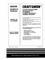
MODEL
MBE
o Assembly
o Operation
Customer
Responsibilities
Service
®Adjustments
• Repair Parts
Caution:
, Read and Follow
; all Safety Rules
and Instructions
, Before Operating
This Equipment
917=255980
OWNER'S MANUAL
SAFETY
Practices RULES
for Ride-On
Safe Operation
Mowers
&
Ii PORTANT: THIS CUTTING MACHINE IS CAPABLE OF AMPUTATING HANDS AND FEETAND THROWING OBJECTS.
FAILURETO OBSERVE THE FOLLOWING SAFETY INSTRUCTIONS
COULD RESULT IN SERIOUS INJURY OR DEATH,
I.
GENERAL
•
Read, understand, and follow all instructionsin the manual
and on the machine before starting.
Only allow responsible adults, who are familiar with the
instructions, to operate the machine.
Clear' the area of objects such as rocks, toys, wire, etc..,
which could be picked up and thrown by the blade_
Be sure the area is clear of otherpeople before mowing. Stop
machine if anyone enters the area.
Never carry passengers°
Do notmow in reverse unless absolutely necessary. Always
look down and behind before and while backing.
Be aware of the mower discharge direction and do not point
it at anyone. Do not operate the mower without either the
entire grass catcher or the guard in place.
Slow down before tuming.
Never leave a running machine unattended, Always turn off
blades, set parking brake, stop engine and remove keys
before d smountingo
Turn off blades when not mowing.
Stop engine before removing grass catcher or unclogging
chute.
•
,
•
°
°
°
°
°
°
•
•
•
°
•
II.
OPERATION
-
IlL CHILDREN
Tragic accidents can occur' if the operator is not alert to the
presence ofchildren, Children are often attracted tothe machine
and the mowing activity. Neverassume that children will remain,
where you last saw them_
•
Keep children out ofthe mowing area and under the watchful
care of another responsible adulL
Be alert and turn machine off if children enter the area.
Before and when backing, look behind and down for small
children_
°
o
°
•
•
Never catty children. They may fall off and be seriously
injured or interfere with safe machine operation.
"Never allow chi[dren to operate the machine.
Use extra care when approaching blind comers, shrubs,
trees, or other objects that may obscure vision..
IV, SERVICE
•
Mow only in daylight or good artificial light°
Do not operate the machine while under the influence of
alcohol or drugs.
Watch for traffic when operating near or crossing roadways.
Use extra care when loading or unloading the machine tnto
a trailer or"truck._
Use extra care in handling gasoline and other fuels They are
flammable and vapors are explosive.
Use only an approved container_
Never remove gas cap or add fuel with the engine
running. Aliow engine [o cool before refueling_ Do not
smoke.
Never refuel the machine indoors.
Never store the machine or fuel container inside where
there is an open flame, such as a watr:r h ater.
Never run a machine inside a closed area
•
°
Keep nuts and bolts, especially blade attachment bolts, tight
and keep equipment in good condition.
Never' tamper' with safety devtces_ Check their proper
operation regularly,
Keep machine free of grass leaves, or other debds build-up,
C ean o t or fuel spillage° Allow machine to cool before
storing.
Stop and inspect the equipment if you stdke an object.
Repair, if necessary, before restarting.
Never make adjustments or repairs with the engine running.
Grass catchercomponents are subject towear', damage, and
deterioration, which could expose moving parts or allow
objects to be thrown. Frequently check components and
replace with manufacturer's recommended parts, when necessary_
Mower blades are sharp and can cut. Wrap the blade(s) or
wear gloves, and use extra caution when servicing them°
Check brake operation frequently_ Adjust and service as
required_
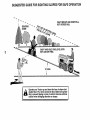
SLOPE OPERATION
°
Slopesare a majorfactor related to loss-of-control
and tipover
accidents,whichcan resultin severeinjury or death. All slopes
requireextracaution.Ifyoucannotbackuptheslopeorifyoufeel
uneasyon it, do not mowiL
DO:
•
Mow upand downslopes, not across.
•
Removeobstaclessuchas rocks,tree limbs,etc.
° Watch for holes, ruts, or bumps. Uneven terraincould
overturnthemachine° Tallgrasscanhide obstac/es
•
Useslow speed..Choosea !owgear sothatyouwillnothave
to stopor shiftwhileonthe slope.
° Follow the manufacturer's recommendations for wheel
weightsor counterweights
toimprove stability.
° Use extra care with grasscatchersor other attachments..
These canchangethestabilityof the machlne_
•
Keep all movementon theslopes s/owand gradual Donot
make suddenChangesin speedor direction_
o Avoid startingor stoppingon a slope. If tireslose traction,
disengagethe bladesand proceedslowlystraightdownthe
slope°
DO NOT:
• _ Donottumonslopesuniessnecessary,
andthen,tumslowty
andgraduallydownhill,if possible
.....
°
Do notmownear'drop-offs,ditches,or embankments.The
mowercouldsuddenlyturnoverif a wheelisoverthe edge
ofa cliffor ditch,or ifan edge cavesin.
°
Do not mow on wet grass_Reducedtractioncouldcause
sliding°
°
Donottrytostabilizethemachinebyputtingyourfootonthe
ground,
°
Do not usegrass catcher on steep slopes,,
•
=
°
•
°
•
ii
i i i
j
J
J
_
J
_
,,,,,,,,,,,,, ,,,,,,
_
AA,
,,_,,_,,,_,,,
I
Lookfor this symbol to point out important safety
precautions.
It means
CAUTIONII!
BECOME ALERTIII
YOUR
SAFETY IS INVOLVED "
.....................................
J
J
.........
iLllll
CAUTION:
Always disconnect
spark
contact spark plug In order to prevent
plug
wire and
place wire
where
it cannot
accidental
starting
when
setting
up,
transporting,
adjusting or making
repairs.
2
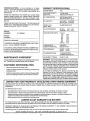
CONGRATULATIONS
on your purchase of a Sears
Tractor. It has been designed, engineered and manufactured to give you the best possible dependability and
performance,
PRODUCT
Should you experience any problem you cannot easily
remedy, please contact your nearest Sears Authorized
Service CenteriDepartmento We have competent, we!_trained technicians and the proper tools to service or repair
this unit.
Please read and retain this manual, The instructions will
enable you to assemble and maintain your unit properly.
Always observe the "SAFETY RULES"°
MODEL
NUMBER
SPECiFiCATIONS
HORSEPOWER:
18_0
GASOLINE CAPACITY
AND TYPE:
3..5GALLONS
UNLEADED REGULAR
OiL TYPE (API-SG):
SAE 30 (above 32°F)
SAE 5W-30 (below 32°F)
OIL CAPACITY:
W! FILTER:
W/O FILTER:
SPARK PLUG:
(GAP: ..025")
917°255980
CHAMPION RV15YC
VALVE CLEARANCE:
INTAKE:
EXHAUST:
GROUND SPEED (MPH):
Forward
1st
2nd
3rd
4th
5th
6th
Reverse
SERIAL
NUMBER
DATE OF PURCHASE
THE MODELAND SERIAL NUMBERS WILL BE FOUND
ON A PLATE UNDER THE SEAT.
YOU SHOULD RECORD BOTH SERIAL NUMBER AND
DATE OF PLJRCHASE AND KEEP IN A SAFE PLACE
FOR FUTURE REFERENCE
MAINTENANCE
AGREEMENT
RESPONSIBILITIES
•
Read and observe
.
Followa regular schedule
using your unit.
the safety rules..
o
Follow the instructions under"Customer
Responsibilities" and "Storage" sections of this owner's manual.
in maintaining,
°003" - °006"
,.016" - o019"
0.75
1.50
250
1.50
3,5O
5.75
2,.25
TRANSAXLE OIL
CAPACITY AND TYPE:
4 QUARTS
SAE 30 API*SG
TIRE PRESSURE:
FRONT:
REAR:
CHARGING SYSTEM:
3 AMPS BATTERY
15 AMPS HEADLIGHTS
BLADE BOLTTORQUE:
30-35 FT,.LBS,.
14 PSI
10 PSi
WARNING: This unit isequipped with an inL_rnal combus*
tion engine and should not be used on or near any unimproved forest-covered, brush-covered or grass-covered
land unless the engine's exhaust system is equipped with
a spark arrester meeting applicable local or state laws (if
any),. If a spark arrester is used, it should be maintained in
effective working order by the operator_
in the state of California the above is required by law
(Section 4442 of the California Public Resources Code).
Other states may have similar laws, Federal laws apply on
federal lands.. A spark arrester for the muffler is available
through your nearest Sears Authorized Service Center/
Department (See R EPAIR PARTS section of this manual).
A Sears Maintenance
Agreement is available on this product., Contact your nearest Sears store for details.
CUSTOMER
4.,0 PINTS
35 PINTS
cadng for and
LIMITED TWO YEAR WARRANTY ON ELECTRIC START RIDING EQUIPMENT
For two (2) years from the date of purchase, if this riding equipment is maintained, lubricated and tuned up according to the
instructions in the owner's manual, Sears will repair or replace, free of charge, any parts found to be defective in material or
workmanship.
This Warranty does not cover:
•
•
°
•
Expendable items which become worn during norma! use, such as blades, spark plugs, air cleaners and belts.
Tire replacement or repair caused by punctures from outside objects, such as nails, thorns, stumps, or glass,
Repairs necessary because of operator abuse, negligence, improperstorage or accident or the failure to maintain the
equipment according to the instructions contained in the owner's manual.
Riding equipment used for commercial or rental purposes,
LIMITED
90 DAY WARRANTY
ON BATTERY
For ninety (90) days from date of purchase, if anY battery included with this riding equipment proves defective in materi!l
workmanship and our testing determines the battery will not hold a charge, Sears will replace the battery at no charge..
or
WARRANTY SERVICE IS AVAILABLE BY RETURNING THE RIDING EQUIPMENT TO THE NEAREST SEARS SERVICE
CENTER/DEPARTMENT IN THE UNITED STATES.
This Warranty gives you specific legal rights, and you may also have ether rights which may vary from state to state_
.....
SEARS,
ROEBUCK
AND CO., 9/817 WA, HOFFMAN
3
ESTATES,
ILLINOIS
60179
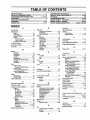
TABLE OF CONTENTS
SAFETY RULES ............................................................ 2
PRODUCT SPECIFICATIONS ...................................... 3
CUSTOMER RESPONSIBILITIES ..................... 3, 16-18 ,_,
WARRANTY ...................... ;,........... (. .................. _,
.......... 3 "_'
TRACTOR ACCESSORIES .......................................... 5
ASSEMBLY .............................................................. 7-10
OPERATION .......................................................... 11-14
MAINTENANCE SCHEDULE ...................................... 15
SERVICE AND ADJUSTMENTS ............................ 19-25
STORAGE ...................................................................
26
TROUBLESHOOTING ........................................... 27-28
REPAIR PARTS - TRACTOR ................................ 31-47
REPAIR PARTS - ENGINE .................................... 48-57
PARTS ORDERING/SERVICE ................ BACK COVER
INDEX
E
A
Operation.................................
11-14
Electrical:
Accessories .............................................................
5
OperatingMower ...........................
13
Intedocks and Relays .................... 23
Adjustments:
Options:
Schematic ....................................................
30
Accessories ............................
5
Brake ................................................2t
Wiring Diagram ...................................
32
Carburetor ........................................ 25
Spark Arrester ..................................
3,40
Engine:
Gauge Wheels ...............................
13
Air Filter .........................................
18
Mower'
P
Air Screen .....................
i.........................18
Front-To-Back ................................
20
ParkingBrake .............................
11-12
Cooling Fins .............................................
18
Side-To-Side ..................................
19
Parts
Bag
.................................
6
Otl Change .....................................................
17
Throttle Control Cable ........................
25
Oil Level ...............................................
17
Parts,
Replacement/Repair
................
31-47
Air Filter, Engine ........................................
18
Oil Type ........................................
13,17
Product Specifications .........................................
3
Air Screen, Engine ......................................
18
Preparation ..........................................
13
Assembly ..........................................................
7-t0
Repair Parts ...........................................
48-57
R
Starting ......................................................
14
Repair
Parts
........................................................
31-47
B
Storage .........................................
26
Battery:
S
F
Charging ................................................
8
Safety
Rules
...............................
2
Filter:
Cleaning ..........................................................
18
Seat
installation
..................................................
i0
Air' Filter ........................................
18
Levels ................................................
8,16
Fuel .................................................................
18
Service and Adjustments .........................
19-25
Oil.........................................................
18
Preparation ....................................
8
Carburetor
....................
i'.
.................
25
Starting with Weak Battery ........... 23
Fuse .................................
23
Fuel:
Storage ......................................................
26
Hood Removaltlnstallation ...........
24
Storage .......................................................
26
Terminals ..............................................
16
Motion Drive Belt
Type .................................................
13
Belt:
Removal/Replacement ...............22
Fuse .......................................................
23
Mower Drive Belt
Motion Drive
RemovaltReplacement ............ 20
Removal/Replacement ..................
22
H
Mower Blade Drive Belt
Mower Drive
Headlights ..........................................................
23
RemovaltReplacement .............
21
RemovallReplacement ............ 20
Hood Removal/Installation ........................
24
Mower Blade Drive
MowerAdjustment
.,
Front-to-Back ........................
20
Removal/Replacement ...................
21
Side-to-Side ..................................
t9
L
Blade:
Mower Removal/Installation ......... 19
Sharpening ............................................
16
Leveling Mower Deck ..................................
19
Tire Care ..............................
8,15,23
Replacement .......................................
16
Lubrication:
Slope Guide Sheet
59
Brake Adjustment .........................................
2t
Chart .....................................................................
t5
Spark Plug(s)..............................
18
Engine.............................................
17
C
Specifications ..............................
3
M
CarburatorAdjustment
..........................
25
Starting
tile
Engine .........................
13-14
Maintenance Schedule .............................
15
Controls, Tractor. .......................................
11
Steering Wheel ..................................................
7,22
Mower:
Customer Responsibilities .................16-18
Stopping the Tractor ...............................12
Adjustment, Front-to-Back ........... 20
Engine:
Storage ..................................
26
Adjustment, Side-to-Side ..................
19
AirFilter
........................................
18
Blade
Replacement
................................
21
Air Screen ............................................
18
T
BladeSharpening .........................
16
Cooling Fins .................................18
Throttle
Control
Cable
Adjustment .......
25
Cutting Height .............................. 12
Engine Oil................................
13,i8
Installation
...........................................
19
Tires .....................................
8,i6,23
Fuel Filter .........................................
18
Operation ..................................................
13
Spark Plug(s) ..................................
18
Troubleshooting Chart ..................... 28-29
Removal .............................................
19
Tractor:
Transaxle .................................
17
Battery
.............................................
16
Mowing Tips ...................
...._._'._::_
...............14
Blade .............................................
16
Muffter_.................................
_._
...........................
18
W
Lubrication Chart ..........................
17
Spark Arrester .................................
3,40
Warranty .................................
3
Maintenance Schedule ......................
15
Tire Care ........................... 8,16,23
Wtdng Diagram ............................
32
0
Transaxie .......................................
17
Wiring Schematic ...........................
30
Oil:
Cutting Height, Mower ..............................
12
Cold Weather Conditions ........ I3,17
...........................................................................
8
..........................................
Engine ..................................................
17
Storage ...................................................
26
4
AN
i1,,11,11,,i
,
i,
i
_ ,
,_
r_r,,_rllll
...............................
_
_:7'::11
ATTACH
i1_
[I
i,'11
i'1,'11,1'
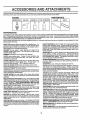
These accessories andattachments were available through most Sears retail outlets and service centers when the tractor was purchased°
Most Sears stores can order these items for you when you provide the model number of your tractor_
MAINTENANCE
ENGINE
SPARK PLUG
GAS CAN
ENGINE OIL
FUEL STABILIZER
BLADES
BELTS
PERFORMANCE
Sears offers a wide variety of attachments that fit yourtractor° Many of these are listed below with brief explanations of how they can help
you. This list was current at the time of publication;however, it may change in future years- more attachments may be added, changes
may be made in these attachments, or some may no longer be available or fit your model. Contact your nearest Sears store for the
accessories and attachments that are available for your tractor.
Most of these attachments do not require additional hitches or conversion kits (those that do are indicated) and are designed for easy
attaching and detaching°
SNOWTHROWER has 40-inch swath. Drum-type augerhandles
powdery and wet/heavy snow. Mounts easily with simple pin
arrangemenL Discharge chute adjusts from tractor seat. 6-Inch
diameter spout discharges snow 10 to 50 feet° Lift controlled at
tractor seat. (Use with chains and wheel weights and/or rear
drawbarweighL)
SPRAYERS use 12wolt DC electric motor that connects to the
tractor battery or other 12-volt source_ includes booms for
automatic spraying and hand held wand forspot spraying. Wand
has adjustable spray pattern° For applying herbicides, insecticides, fungicides and tiquidfertilizers,
'
SPREADER/SEEDERS make seeding, fertilizing, and weed killing easy. Broadcast spreaders are also useful for granular deicers and sand.
SWEEPERS let you collect grass clippings and leaves°
TILLER cultivates and prepares soil In one operation° Uses PTO
from tractor; 12 counter-rotating blades.. Breaks ground with
upper-cut action, then deflects and retills it into a soft, aerated soil.
Chain-drive transmission. Tills 2t-Inch path, 6-inches deep_ (Use
chains and wheel weightso)
TILLER has 8 hp engine to prepare seed beds, cultivate, and
compost garden restdue_ Chaimdrive transmission. Six 1l-inch
diameter one piece heat-treated steel tines. Tills 30-1nch path°
(Requires sleeve hitch°) Or use 5 hp tow-behind TILLER with
36-inch swath to prepare seed beds, cultivate and compost
garden residue. Tiller has its own built-in lift and depth control
system and does NOT require a sleeve hitch° Fits any lawn,yard
or garden tractor. Simply hook up to the tractor drawbar andgol
Optional accessories for 5 hp tiller convert unit for dethatching,
aerating, hilling...without toots
TIRE CHAINS are heavy duty; closely spaced extra-large cross
linksgive smooth fide, outstanding traction°
TRACTOR CAB has heavy duty vinyl fabric over tubular steel
frame, ABS plastic top; clear plastic windshield offers 360 degree
visibility. Hinged metal doors with catch. Keeps operatorwarm
and dry° Remove vinyl sides and windshields for use as sun
protector in summer. Optional accessories include: tinted/
tempered solid safety glass windshield with hand operated wiper;
12-volt amber caution light for mounting on cab top.
VACSforpowerfulcollection
of heavy grass clippings and leaves.
Optional wand attachment to pick up debris in hard-to-reach
places. VAC/CHIPPER includes a chipper-shredder_
WEIGHT BRACKET for drawbar for snow removal applications.
Uses (1) 55 ib_ weight.
WHEEL WEIGHTS for rear wheels provide needed traction for
snow removal or dozing heavy materials.
AERATOR promotes deep root growth for a healthy lawn. Tapered 2.5-inch steel spikes mounted on 10-inch diameter discs
puncture holes in soil at close Intervals to let moisture soak in.
Steel weight tray for increased penetration°
BAGGER lets you collect grass clippings and leaves for a
healthier, neater looking lawn. Two Permanex containers hold
30_gallon plastic bags.
BUMPER protects front end of tractor from damage.
CARTS make hauling easy. Variety of sizes available, plus
accessories such as side panel kits, tool caddy, cart cover,
protective mat and dolly
CORING AERATOR takes small plugs out of soil to allow moisture and nutrients to reach grass roots. 36-inch swath
24
hardened steel coring tips. 150 Ib capacity weight tray.
EASY OIL DRAIN VALVE makes oil changes easier, faster.
FRONT NOSE ROLLER cantersin front of mower deckto reduce
chances of "scalping" on uneven terrain.
GANG HITCH lets you tow 2 or3 pull-behind attachments at once,
such as sweepers, dethatchers, aerators (not for use with rollers,
carts or other heavy attachments).
GAUGE WHEELS on both sides of the mower deck reduce
chances of "scalping" on uneven terrain. For mower decks not so
equipped.
MULCH RAKE/DETHATOHER loosens soil and flips thatch and
matted leaves to lawn surface for easy pickup. Twenty spring tine
teeth. Usefultoprepare bareareasforseeding.
Available forfront
or rear mounting.
HIGH PERFORMANCE REEL-ACTION
SPRING TINE DETHATCHER covers 36-inch wide path and
tosses thatch into large hopper. Mounts behind tractor.
MULCHING KIT, once installed, lets you mulch, discharge orbag
clippings (bagger optional) without changing blades. For models
not equipped as 3-in-1 Convertible mowers.
RAMP TOPS AND FEET let you load and unload tractor from a
pickup truck. Use with 2 x 8 or2 x 10 lumber°
ROLLER for smoother lawn surface. 36-inch wide, 18-inct_
diameterwater-tlght drum holds upto 390 Ibs ofweighL Rounded
edges prevent harm to turf. Adjustable scraper automatically
cleans drum,
SNOW BLADE for snow removalonly. 14-inch hlgh,42-inch wide
blade clears 38-inch path when angled left or right.. Raises, bowers
with side lever. Adjustable skids; replaceable, reversible scraper
bar. (Use with tire chains and wheel weights and/or reardrawbar
weight..)
5
OF HARDWARE
III
I
I
I
I J
PACK
L Jlllll'lllll
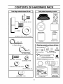
Parts Bag contents shown full size
Parts packed separately
Seat
in carton
Battery acid
(1) Shoulder Bolt 5/!6-18
l
(1) Knob
I
Battery
Steering Wheel
uL,
iL :
:_::=_
(1) W'asher 17132x 1-3/16 x 12 Gauge
Owner's rianual
Parts Bag
Parts bag contents not shown full size
(3) Retainer Springs
12/Gauge
VVheelsi__
}::::]
"_l_]
©
_(
._. _
.....
_
{z_ _noutaer _ol[s
(4) Retainer Springs
(u._j/j
(2) Crown
(2) Washers Lock Nuts
3t8 x 3/4 x 14 Gauge
"_ i2_
Fro.,
L'."Aosomb"eo
I_llllftlttllllllltlllll!l!U
@
(2) Keys
(2) Hex Bolts 1/4-20 x 3/4
(2) Battery Carriage Bolts 1/4-20 x 7..112
(2) Hex Nuts 1/4-20
Termfnal Guard
Steering Wheel Insert
(2) Washers 9/32 x 5/8 x 16 Ga.
(2) Lock Washers 1/4
, _
,,,
, ,
['
(2) Wing Nuts 1/4-20
15° Slope Sheet
t lu,lllull,
6
Battery caps
and Instructions
BLY
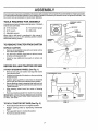
Your new tractor has been assembled at the factory with exception of those parts left unassembled for shipping purposes.
To ensure safe and proper operation of your tractor all parts and hardware you assemble must be tightened securely. Use
the correct tools as necessary to insure
proper tightness.
t.
TOOLS REQUIRED
FOR ASSEMBLY
/
A socket wrench set will make assembly easier, Standard
wrench sizes are listed°
(2) 7/16" wrenches
(1) Tire pressure gauge
(1) 9/16" wrench
(1) Utility knife
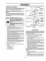
STEERING WHEEL
INSERT
_,_HEX
BOLT
(1) Adjustable wrench
FLAT
When right or left hand is mentioned in this manual, it
means when you are in the operating position (seated
behind the steering wheel).
TO REMOVE TRACTOR FROM CARTON
UNPACK
°
o
°
CARTON
Remove all accessible loose parts and parts cartons
from carton (See page 6).
Cut, from top to bottom, along lines on all four corners
of carton, and lay panels fiat.
Check for any additional loose parts or cartons and
remove.
STEERING
SHAFT
STEERING
WHEEL
ADAPTER
.
/
/
/
BEFORE
ROLLING
ATTACH STEERING
°
°
°
o
=
TRACTOR
OFF SKID
FIG. 1
WHEEL (See Fig. 1)
Remove hex bolt, lock washer and large flat washer
from steering shaft.
Position front wheels of the tractor so they are pointing
straight forward,
CLUTCHJBRAKE
LIFT
LEVER
Position steering wheel so cross bars are horizontal
(left to right) and slide onto steering wheel adapter°
Secure steering wheel to steering shaft with hex bolt,
lock washer and large fiat washer previously removed.
Tighten securely,
Snap steering wheel insert into center of steering
wheel.
= Remove protective plastic from tractor hood and grill.
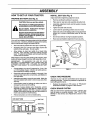
IMPORTANT: CHECK FOR AND REMOVE ANY STAPLES
IN SKID THAT MAY PUNCTURE TIRES WHERE UNIT IS
TO ROLL OFF SKID.
TO ROLL TRACTOR
Raise attachment lift lever to itshighest position°
=
Release parking brake by depressing clutch/brake
pedal°
Place gearshift lever in neutral (N) position.
Roll unit backwards off skid_
PARKING
BRAKE
GEARSHIFT
LEVER
FIG. 2
OFF SKID (See Fig. 2)
°
°
o
PEDAL
7
ASSEMBLY
HOW TO SET UP YOUR TRACTOR
PREPARE
I
_
BATTERY
I'
INSTALL SEAT (See Fig. 4)
Adjust seat before tightening adjustment knob_
(See FJg._3)
ii
iij
iiiiiii
i
ii
°
IIII
Remove cardboard packing on seat pan.
CAUTION: Wear eye and face shield.
°
Place seat on seat pan and assemble shoulder boll
Wash hands or clothing immediately if
•
Assemble adjustment knob and fiat washer loosely.
Do not tighten.
Tighten shoulder bolt securely.
°
Do
not smoke.
Fumes
from
charged
accidentally
in contact
with
batlen]acid.
battery acid are explosive.
Read the instructions included with the
battery vent caps. Always wear gloves,
clothing and goggles to protect your
hands, skin and eyes.
°
Lower seat into operating position and sit on seat.
°
Slide seat until a comfortable position is reached which
allows you to press clutch/brake pedal all the way
down.
•
Get off seat without moving its adjusted position.
°
Raise seat and tighten adjustment knob securely.
Your unit has a battery charging system which is sufficient
for normal use. However',periodic charging of the battery
with an automotive charger will extend its life.
•
See instructionspacked with vent caps in parts bag.
°
Fill batter] with acid. Filt each cell until it reaches the
bottom of the vent wells. Do not overfill.
•
Allow battery to stand and settle for at least thirty
minutes° After standing, check the battery cell acid
teveL If below the vent wells, add more acid until the
correct level is reached.
SEAT
SEAT PAN
SHOULDER
BOLT
While battery is standing (after adding acid) and later, while
battery is being charged, continue with assembly of unit.
IMPORTANT:
TO MAXIMIZE
THE LIFE OF YOUR
BATTERY, IT IS NECESSARY THAT THE BATTERY BE
CHARGED
BEFORE
USE. FAILURE
TO CHARGE
BATTERY CAN RESULT IN A SHORTENED
BATTERY
LIFE.
•
FLAT
WASHER
ADJUSTMENT
KNOB
Charge battery at a rate of 6 amperes for 1 hour. Use
a 12 volt battery charger'. Observe all safety precautions required for battery charging°
Check the acid level after the battery is charged. If the
acid has fallen below the correct level, add distilled or
iron free water°
CHECK TIRE PRESSURE
°
install the vent caps to cover the vent wells. Wash the
top of the battery with water to remove any acid, then
wipe dry_
The tires on your' unit were overinflated at the factory for
shipping purposes. Correct tire pressure is Important for
best cuttingperformancm
•
Check battery case for leakage to make sure that no
damage has occurred in handling..
°
•
Dispose of excess battery acid. Neutralize acid for
disposal by adding it to two gallons of water in a five
gallon plastic container. Stir with a wooden or plastic
paddle while adding baking soda until the addition of
more soda causes no more foaming.
°
°
FIG. 4
CHECK BRAKE SYSTEM
After you [earn how to operate your' tractor',check to see
that the brake is properly adjusted° See "TO ADJUST
BRAKE" in the Service and Adjustments section of this
manual.
Follow instructionson how to install battery.
CUT AWAY VIEW
!
,.r._
VENT CAP
I
VENT WELL
BATTERY
CELL ACID
LEVEL
FIG. 3
Reduce tire pressure to PSt shown in "PRODUCT
SPECIFICATIONS on page 3 of this manual.
8
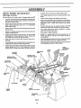
INSTALL MOWER AND DRIVE BELT
(See Figs. 5 and 8)
°
•
Be sure tractor ison level surfacel Engage parking bra!_o
o
o
°
o
=
°
o
Cut and remove tie down wire between anti-sway bar
and R.Hogauge wheel bracket.,Swing anti-sway barto
left side of mower deck,.
' Place the suspension arms on deck pins. If necessary,
raise front of mower to align deck pins with the holes tn
suspension arms,, Retain with double loop retainer
springs,,
•
Connect anti-sway bar to chassis bracket under left
footrest and retain with double loop retainer spring.
o
Relieve idler tension from belt, Push idler forward and
place a block (standard wood 2 x 4 or equivalent)
behind idler pulley.
Slide mower undertractorwith dischargeguardto right
side of tractor°
Swing LH. gauge wheel bar forward by removing rear
retainer spring and pin°
Instali one front link in top hole of the L.H. front mower
bracket and L.H. front suspension bracketoRetain with
two single loop retainer springs as shown.
Slide right side of mower deck forward, toward R.H.,
front tire,
=
Checkbelt for properroutingin all mowerpulleygrooves.,
install belt into eiectric clutch pulteygroove.
o
lnstall second front linkin the top hole ofthe R°H. front
mower bracket and R.Ho front suspension bracket.
Retain with two single loop retainer springsas shown,
Carefully remove block from behind idler puUey_
Turn height adjustment knob counterclockwise until it
_stopso
Lower mower linkage with attachment lift lever.
•
Turn height adjustment knob clockwise to remove
slack from mower suspension_
o
•
Raise deck to highest position°
Swing Loll, gauge wheel bar back towards rear of
mower and secure with pin and retainer spring removed earlier.
°
Assemble gaugewheels as shown using tong shoulder
bolts, 3/8 washers and nuts. Tighten securely.
°
Adjust gaugewheels before operating mower as shown
in the Operation section of this manual,.
SUSPENSION
ARMS
CHASSIS
BRACKET
DOUBLE LOOP
RETAINER SPRING
DOUBLE LOOP
RETAINER SPRING
FRONT
LINKS
FRONT
SUSPENSION
BRACKET
ELECTRIC
CLUTCH
PULLEY
LH. GAUGE
WHEEL BAR
FRONT
SUSPENSION
BRACKET
SINGLE
LOOP RETAINER
_IGS
SHOULDER
BOLT
BRACKET
NUT
ANTI-SWAY
BAR
3_ WASHER
IDLER
PULLEY
GAUGE
WHEEL
BLOCK
(Wood 2 x 4 or equivo)
DISCHARGE
GUARD
FIG. 5
9
BLY
CHECK DECK LEVELNESS
For best cuttingresults, mower housing shouldbe properly_.
leveled_ See "TO LEVEL MOWER HOUSING" in the_,
Service and Adjustments section of t his manual
CHECK
BELTS
FOR PROPER
POSITION
HEX BOLT
OF ALL
(NEGATIVE)
BLACK CABLE
See the figures that are shown for replacing motion, mower
drive, and mower blade drive belts in the Service and
Adjustments section of this manual, Verify that the belts are
routed correcUy.
LOCK WASHER
DRAIN TUBE
FIG. 6
INSTALL BATrERY
(See Figs. 6 and 7)
CAUTION: Do not short battery terminals. Before installing battery, remove
rings,
metal etc.
bracelets, wristwatch bands,
Positive terminal must be connected
first to prevent sparking from accidental grounding.
•
Lift hood to raised position.
°
Be sure batter_j drain tube has not come loose and is
securely attached to drain in battery tray.
o
Lower battery into batterytraywith
tractor.
°
First connect RED battery cable to positive (+) battery
terminal with hex bolt, flat washer, lock washer and hex
nut as showrL Tighten securely.
•
Connect BLACK grounding (_bleto negative (-) battery
terminal with remaining hex bolt, flat washer, lock
washer and hex nut.. Tighten securely,,
Slide the two battery bolts through the terminal guard
and start the wing nuts onto the threads.
Position terminal guard over battery as shown, lower
battery bolts into key holes and slide square shafts of
batter7 bolts into slots of key holes.
°
o
FIG. 7
terminals to front of
,/CHECKLIST
BEFORE YOU OPERATE AND ENJOY YOUR NEW
TRACTOR, WE WISH TO ASSURE THA T YOU RECEIVE
THE BESTPERFORMANCEAND SATISFACTION FROM
THIS QUALITY PRODUCT.
PLEASE REVIEW THE FOLLOWING CHECKLIST:
Inspection for secure connections (to tighten hard*
ware).
Inspection for corrosion°
•
,
Testing battery_
Jumping (if required),.
•
Periodic charging°
,/
,/
No remaining loose parts in carton.
Battery is properly prepared and charged. (Minimum
1 hour at 6 amps).
Seat is adjusted comfortably and tightened securely.
All tires are properly inflated. (For shipping purposes,
the tires were overinflated at the factory).
#" Be sure mower' deck is properly leveled side-to-side/
front-to-rear for' best cutting results. (Tires must be
properly inflated for' leveling).
4" Check mower-and drive belts. Be sure they are routed
properly around pulleys and inside all belt keepers..
#" Check wiring. See that all connections are still secure
and wires are properly cIamped.
Tighten wing nuts by hand making sure battery bolts
remain in slots of the key holes in the battery support.
° Be sure terminal access doors are closed°
Use terminal access doors for:
•
All assembly instructions have been completed°
,/
,/
°
.
,/
WHILE LEARNING HOW TO USE YOUR TRACTOR, PAY
EXTRAA TTFEIVTIONTO THE FOLLOWING IMPORTANT
ITEMS: _"
::j
v'
Engine oil is at proper level,
Fuel tank is filled with fresh, clean, regular unleaded
gasoline.
Become familiar with all controls - their location and
function° Operate them before you start the engine.
Be sure brake system is in safe operating condition_
10
OPERATI
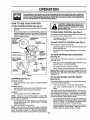
KNOW YOUR TRACTOR
READ THIS OWNER'S
MANUAL AND SAFETY RULES BEFORE OPERATING
YOUR TRACTOR.
Compare the illustrationswith youPtractorto familiarize yourselfw_ththe locationof various controlsand adjustments° Save
this manual for future reference,,
LIGHT SWITCH
THROTTLECONTROL
ATTACHMENT
CLUTCH SWITCH
AMMETER
CLUTCH/BRAKE
PEDAL
LIFT LEVER
IGNITION SWITCH
CHOKE CONTROL
PARKING BRAKE
LEVER
HE1GHTADJUSTMENT
KNOB
RANGESHtFT
LEVER
GEARSHIFT LEVER
FIG, 8
Our tractors conform to the safety standards of the American National Standards Institute_
RANGE SHIFT t.EVER - Allows "HI" or "LO" speed for all
forward and reverse gears,,
IGNITION SWITCH - Used to start and stop the engine.
AMMETER - Indicates battery charging (+) or discharging
ATTACHMENT CLUTCH SWITCH- Used to engage mower
blades or other attachments mounted to your tractor°
LIFT LEVER- Used to raise and lowermower deck or other
attachments mounted to yourtractor_
CLUTCH/BRAKE PEDAL - Used for declutching and
braking the tractor and starting the engine°
GEARSHIFT LEVER - Selects the speed and direction of
tractor.
THROTTLE CONTROL _ Used to control engine speed.
(-).
LIGHT SWITCH - Turns the headlights on and off.
PARKING BRAKE LEVER - Locks clutch/brake pedal into
the brake position.
CHOKE CONTROL - Used when starting a cold engine°
HEIGHT ADJUSTMENT KNOB- Usedto &djust the mower
height.
11
The operation of any tractor can result in foreign objects thrown into the eyes, which can
result in severe eye damage, Always wear safety glasses or eye shields while operating your
tractor or pe_orminganyadjustme_s
or repaizs. We recommend a wide vision safety mask
for over the spectacles or standard safety glasses,
HOW TO USE YOUR TRACTOR
TO SET PARKING
CAUTION: Always stop tractor completely, as described above, before leaving the operator's position; to empty
grass catcher, etc.
BRAKE (See Fig. 9)
•
Depress clutch/brake pedal intofull"BRAKE" position
and hold.
•
Place parking brake lever in"ENGAGED"position and
release pre,ssure from clutch/brake pedal. Pedal should
remain in BRAKE position. Makesure parking brake
will hold vehicle secure.
ATTACHMENT
CLUTCH
SWITCH
TO USE CHOKE CONTROL
•
"DISENGAGED"
POSITION
THROTTLE
CONTROL LEVER
POSITION
(See Fig. 9)
Use choke control whenever you are starting a cold engine_
Do not use to start a warm engine.
To engage choke control, pull knob out. Slowly push
knob in to disengage.
TO USE THROTTLE
CONTROL
(See Fig. 9)
Always operate engine at full throttle.
_
PARKING
IGNITION
BRAKE
"ENGAGED"
Operating engine at less than full throttle reduces the
battery charging rate,_
•
Full throttle offers the best bagging and mower performance_
TO MOVE FORWARD
(See Fig, 9)
CHOKE
POSITION
CLUTCH/BRAKE
PEDAL "BRAKE"
POSITION
•
"DISENGAGED"
The direction and speed of movement is controlled by the
gearshift leven
r_
•
"DRIVE"'
POSITION
"<"_
HEIGHT
ADJUSTMENT
KNOB
GEARSHIFT
LEVER
AND BACKWARD
Start tractor with clutch/brake pedal depressed and
gearshift lever in neutral (N) position.
•
Move gearshift lever to desired position_
•
Slowly release clutch/brake pedal to start movement.
IMPORTANT; BRING TRACTOR TO A COMPLETE STOP
BEFORE SHIFTING OR CHANGING GEARS. FAILURE
TO DO SO WILL SHORTEN THE USEFUL LIFE OF YOUR
TRANSAXLE.
RANGE
SHIFT
LEVER
FIG. 9
STOPPING
TO ADJUST MOWER CUTTING
(See Fig, 9)
(See Fig. 9)
MOWER BLADES •
Move attachment clutch switch to "DISENGAGED"
position,
The cutting height iscontrolled by turning the height adjustment knob in desired direction.
•
•
Turn knob clockwise (F_) to raise cutting height.
Turn knob counterclockwise (_)
to lower cutting
height.
The cutting height range is approximately 1-1/4" to 4-1/4".
The heights are measured from the ground to the blade tip
with the engine not running° These heights are approximate and may vary depending upon soil conditions, height
of grass and types of grass being mowed_
° Theaveragelawnshouldbecuttoapproximately2-1/2
inches during the cool season and to over 3 Inches
during hot months. For healthier and better looking
lawns, mow often and after moderate growth°
GROUND DRIVE •
Depress clutch/brake pedalinto fuII"BRAKE" position°
•
Move gearshift lever to neutral (N) position.
ENGINE •
Move throttIe control to sIow ('_) position.,
NOTE: Failure to move throttle control to slow (,_)
position and allowing engine to idle before stopping may
cause engine to "backfire",
•
Turn ignition key to "OFF" position and remove key.
Always remove key when leaving tractor to prevent
unauthorized use,
•
Never use choke to stop engine.
NOTE: Under certain conditions when tractor is standing
idlewith the engine running, hot engine exhaust gases may
cause "browning" of grass. To eliminate this possibility,
always stop engine when stopping tractor on grass areas..
HEIGHT
=
12
For best cutting performance, grass over 6 inches in
height should be mowed twice. Make the first cut
relatively high; the second to desired heighL
OPERATION
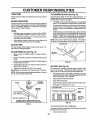
TO ADJUST
GAUGE WHEELS
o
°
Adjust mower to desired cutting height,
Lower mower with lift control Removeo_ear retainer
spring and clevis pin which s_cure each gauge wheel,
•
Lower gauge wheels to ground° Raise gauge wheels
slightly to align holes in bracket and gauge wheel bar,
and insert clevis pins, Gauge wheels should be slightly
off the ground°
°
TO OPERATE
(See Fig. 10)
I
Replace retainer springs into clevis pins.
RETAINER
SPRING
_&
ON HILLS
CAUTION: Do not drive up or down
hills with slopes greater than 15° and
do notdriveacros s any slope.
......
I
I
I
o
Choose the slowest speed before starting up or down
hitls.
o
Avoid stopping or changing speed on hillso
o
If slowing is necessary, move throttle control lever to
slower position.
o
If stopping is absolutely necessary, push clutch/brake
pedal quickly to brake position and engage parking
brake.
CLEVIS
Move gearshift lever to 1st gear and range shift lever to
low (L) position°Be sure you have allowed room for unit
to roli slightly as you restart movement.
GAUGE
WHEEL BAR
o
o
GAUGE
WHEEL
TO TRANSPORT
TO OPERATE
BRACKET
o
Raise attachment lift to highest position with attachment lift control,
FIG. 10
°
When pushing or towing your tractor, be sure gearshift
lever is in neutral (N) position.
°
Do not push or tow tractor at more than five (5) MPH°
MOWER (See Fig. 8 and 9)
NOTE: To protect hood from damage when transporting
your tractor on a truck or a trailer, be sure hood isclosed and
secured to tractor, Use an appropriate means of tying hood
to tractor (rope, cord, etco)o
Yourtractor isequipped with an operatorpresence sensing
switch° Any attempt by the operator to leave the seat with
the engine running and the attachment clutch engaged wifl
shut off the engine.
•
o
o
I_
To restart movement, slowly release parking brake and
clutch/brake pedal,
Make all turns slowly.
Select desired height of cut,
Lower mower with attachment lift control
BEFORE
STARTING
THE ENGINE
Start mower blades by engaging attachment dutch
control°
•
The engine in yourtractor has been shipped, from the
factory, already filled with summer weight oil.
TO STOP MOWER BLADES - disengage attachment
clutch control°
°
°
Check engine oil with tractor on level ground.
Remove oilfill cap/dipstick and wipe clean, reinsertthe
dipstick and push itall the way down into the tube, wait
for a few seconds, remove and read oil level. If
necessary, add oil until "FULL" mark on dipstick is
reached. Do not overfill.
.
For coldweather operation you should change oil for
easier starting (See OIL VISCOSITY CHART" in the
Customer Responsibilitiessection of this manual).
°
To change engine oil, see the Customer Responsibilities section in this manual,
CHECK ENGINE OIL LEVEL (See Fig. 12)
without either the entire grass catcher,
onAUTION:
mowers Do
so not
equipped,
disoperate or
thethe
mower
charge guard in place.
\
_R.H.
ENGINE OIL
FILLER CAP/DIPSTICK
RUNNER
DI,sCHARGE
GUARD
FIG. 11
13
FIG. 12
ADD GASOLINE
MOWING TIPS
•
Fi!! fuel tank. Use fresh, clean, regular unleaded
gasoline. (Use of leaded gasolin._ willi_q.cr_a,_ca_o_'-;
and lead oxide deposits and reduce v_a'lvelire)_ .....
IMPORTANT: WHEN OPERATING IN TEMPERATURES
BELOW 32°F(0°C), USE FRESH, CLEAN WINTER GRADE
GASOLINE TO HELP INSURE GOOD COLD WEATHER
STARTING_
WARNING: Experience indicates that alcohol blended
fuels (called gasohol or' using ethanol or methanol) can
attract moisture which leads to separation and formation of
acids during storage. Acidic gas can damage the fuel
system of an engine while in storage. To avoid engine
problems, the fuel system should be emptied before storage of 30 days or longer. Drain the gas tank, start the
engine and let it run until the fuel lines and carburetor are
empty. Use fresh fuel next season. See Storage Instructions for' additional information. Never use engine or
carburetor' cleaner' products in the fuel tank or permanent
damage may occur.
l&
°
Tire chains cannot be used wilen the mower housing
is_attachedto tractor.
°
Mower should be properly leveled for best mowing
p_rformance_ See"TO LEVEL MOWER HOUSING in
the Service and Adjustments section of this manual.
°
Use the runner on the dght hand side of mower as a
guide. The blade cuts approximately an inch outside
the runner (See Fig.. 11)_
The left hand side of mower should be used for trimming.
°
°
•
fi!lerneck. Do notoverfili. Wipe offany
spilled oil or fuel. Do not store, spill or
CAUTION: Fill to bottom of gas tank
use gasoline near an open flame.
•
•
TO START
ENGINE
(See Fig. 9)
When starting engine for the first time or if engine has run
out of fuel, it willtake extra cranking time to movefuel from
the tank to the engine.
•
Depress clutch!brake pedal and set parking brake_
°
Place gearshift lever in neutral (N) position.
°
Move attachment clutch to "DISENGAGED" position.
°
Pull choke control out to choke (kl) positionfor cold
eng ne start° For warm engine start do not use ctloke
contmL
•
Move throttlecontrolto midway between fast (._) and
s!ow (,_) positions.
•
•
•
Drive so that clippings are discharged onto the area
that has been cut. Have the cut area to the right of the
tractor.. This will result.in a more even distribution of
clippings and more unif_xm cutting.
When mowing large areas, start by turning to the right
so that clippings will discharge away from shrubs,
fences, driveways, etc, After one or'two rounds, mow
in tire opposite direction making left hand turns until
finished (See Fig_ 13).
If grass is extremely tall, it should be mowed twice to
reduce load and possible fire hazard from dried clippings. Make first cut relatively high; the second to the
desired heighL
Do not mow grass when it is wet, Wet grass will plug
mower and leave undesirable clumps. Allow grass to
dry before mowing.
Always operate engine at full throttle when mowing to
assure better' mowing performance and proper discharge of material, Regulate ground speed by selecting a low enough gear' to give the mower cutting
performance as well as the quality of cut desired.
When operating attacttments, select a ground speed
that will suit the terrain and give best performance of
the attachment being used.
insertkeyintoIgnition and turnkeyclockwiseto"START"
positionand release key as soon as engine starts. Do
not run starter continuously for more than fifteen
seconds per rninute_ If engine does not start after
several attempts, move throttle control to fast (,f_)
position,wait a few minutes and try again.
•
When engine starts, slowly push choke control in.
•
°
Move throttle control to fast (_) position°
Allow engine to warm up for a few minutes before
engaging drive or attachments..
,i(
NOTE: If at a high altitude (above 3000 feet) or in cold
temperatures (below 32°F), the carburetor'fuel mixture
may need to be adjusted for best engine performance. See
'q'O ADJUST CARBURETOR" in the Service and Adjustments section of this manual
FIG. 13
14
CUSTOP,!I
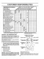
MAINTENANCE
SCHEDULE
/'__o
_"_o__/
AS YOU COMPLETE
_'__Z_.?,-_Z_og-_"
REGULAR SERV!C_E_..........................................
__'_SERVICE
CheckB keOporation
"
...........
C
CheckTire Pressure
i 6_
Checkfor LooseFasteners
i_
0
LubricationChart
.Check.Batte.rY
Level/Recharge ................
"
'
Clean Batteryand Terminals
R
CheckTransaxleCooling
"
!
:
:
:
6#4
6#4
6#4
__
...................................
6##'
_
6##
6#_'_
$_s
.
I
.
=
=
,
6#4
• . z ................. _
!
:
6_
ChangeEngine Oil
E CleanAir Filter
N uCleanAir Screen
G inspect Muffler/SparkArrester
=
6#4
Adjust Blade Belt(s) Tension
........................
Adjust Motion Drive Belt(s)Tension
CheckEngine Oil Level
:
DATES
64_
_
6#_'12,3
6#_'2
!#42
.................
u
i
i
, ,
64#
'
"
_................
6#4 ................................
_,2
ReplaceOil Filter (If equipped)
c,oon
Eng!ne
ooo,,oo .....
ReplaceSpark Plug
ReplaceAir Filter PaperCartridge
Replace Fue,!,,Fitter
._ . 6_
If'2
...........................
1 - Change more often when operating under a heavy load or in high ambtent temperatures
2. - Service more often when operaling tn dirty or dusty condtltons.
GENERAL
.......
_/ .....
3 * If equipped wilh oil filter, change oil eve_ 50 hours.
4 - Replace blades more elten when mowing in sandy sell
5 - If equtpped wi_h adjustable system.
RECOMMENDATIONS
LUBRICATION
The warranty on this tractor does not cover items that have
been subjected to operator abuse or negligence. To
receive full value from the warrant€, operator must maintain
tractor as instructed in this manual
CHART
(_)TIE ROD BALL JOINTS
(_) SPINDLE ZERK __
Some adjustments will need to be made periodically to
properly maintain your tractor.
® F.ONT
All adjustments in the Service and Adjustments section of
this manual should be checked at least once each season°
BEARING Z E RK__
o
°
Check tire pressure.
Check for loose fastener&
=.........
BEARING ZERK
"ENGINE(_)
SECTOR GEAR
TEETH
(#
BEFORE EACH USE
Check engine oil level,,
Check brake operation_
ZERK®
FRONT WHEEL®
@
Once a year you should replace the spark plug, clean
or replace air filter, and check blades and belts for
wear. A new spark plug and clean air filter assure
proper air-fuel mixture and help your engine run better
and last longer.
°
o
,_SPINDLE
TRANSAXLE
FLUIB _
(D SAE 30 MOTOR OIL API - SG
IMPORTANT:
DO NOT OIL OR GREASE THE PIVOT POINTS
WHICH HAVE SPECIAL NYLON BEARINGS°
VISCOUS LUBRICANTS WILL ATTRACT DUST AND DIRT THAT WILL SHORTEN
THE LIFE OF THE SELF-LUBRICATING
BEARINGS,
IF YOU
FEEL THEY MUST BE LUBRICATED, USE ONLY A DRY, POWDERED GRAPHITE TYPE LUBRICANT SPARINGLY.
®
GENERAL PURPOSE GREASE
(_) REFER TO CUSTOMER RESPONSIBILITIES
(_
15
SPRAY
SILICONE
LUBRICANT
{MOVE
"ENGINE"
BOOTS
SECTION
TO LUBRICATE)
TRACTOR
TO SHARPEN
Always observe safety rules when performing any mainte-..
nance.
Care should be taken to keep the blade balanced, An
unbaPancedbladewillcause excessive vibration and eventual damage to mower' and engine_
BRAKE OPERATION
•
If tractor requires more than six (6) feet stopping distance
at high speed in highest gear, then brake must be adjusted.
(See 'q'O ADJUST BRAKE" in the Service and Adjustmerits section of this manual).
•
TIRES
°
BLADE (See Fig. 15)
The blade can be sharpened with a file or on a grinding
wheel., Do not attempt to sharpen while On the mower°
To check blade balance, you will need a 5/8" diameter
steel bolt, pin, or a cone balancer. (When using a cone
batancer, follow the instructions supplied with balancer).
°
Maintain proper air pressure in all tires (See "PRODUCT SPECIFICATIONS on page 3 of this manual).
*
Keep tires free of gasoline, oil, orinsect control chemicals which can harm rubber.
Slide blade on to an unthreaded portion of the steel bolt
or pin and hold the bolt or' pin parallel with the ground.
If blade is balanced, it should remain in a horizontal
position, tf either' end of the blade moves downward,
sharpen the heavy end until the blade is balanced.
°
Avoid stumps, stones, deep ruts, sharp objects and
other hazards that may cause tire damage.
NOTE: Do not use a nail for balancing blade° The lobes of
the center hole may appear to be centered, but are not.
BLADE CARE
For' best results mower blades must be kept sharp° Re_
place bent or' damaged blades.
BLADE REMOVAL
(See Fig. 14)
°
Raise mower to highest position to allow access to
blades.
.
Remove hex bolt, lock washer' and flat washer securing
blade.
o
Install new or' resharpened blade with trailing edge up
towards deck as shown°
°
Reassemble hex bolt, lock washer and flat washer in
exact order as shown°
FIG. 15
BATTERY (See Fig. 16)
•
Tighten bolt securely (30-35 Ft. Lbs. torque).
IMPORTANT: BLADE BOLT IS GRADE 8 HEAT TREATED.,
Your tractor has a battery charging system which is sufficient for normal use, However. periodic charging of the
battery with an automotive charger'will extend its life_
NOTE: We do not recommend sharpening blade- but if you
do, be sure the blade is balanced,,
•
Acid solution level in each battery cell should be even
with bottoms of ventwells. AddonlydistUledoriron free
water if necessary° Do not overfill,
°
•
Keep battery and terminals clean,
Keep battery bolts tight,
°
Keep vent capstightand smaUvent holes in caps open,.
°
Recharge at 6 amperes for i hour,
CUT AWAY VIEW
_
_
_
IJ
_
VENT cAP
VENT
BATTERY
LEVEL
*A GRADE 8 HEAT TREATED BOLT CAN BE
IDENTIFIED BY SiX LINES ON THE BOLT HEAD°
FIG. 16
FIG. 14
TO CLEAN BATTERY AND TERMINALS
Corrosion and dirt on the battery and terminals cart cause
the battery to "Eeak"power.,
-
16
Open battery box door,.
PO
CUSTOMER
o
Disconnect BLACK battery cable first then RED battery cable and remove battery from tractor°
•
Wash battery with solution1 of fou_,_tablespoons;,0t_
bakingsodatoonegallon
ofwater, Becareful nottoget
the soda solution into the cells.
•
Rinse the battery with plain water and dry°
°
Clean terminals and battery cable endswith wire brush
until bright.
SAE VISCOSITY
I =F
•
Coat terminals with grease or petroleum jelly.
°
Reinstall battery (See "INSTALL BATTERY" in the
Assembly section of this manual)°
BmL E$
"20 =
ioc -30,°
0°
,
"20 _'
TEMPERATURE
30 _
;
-1 _
32"
GRADES
,10"
.....
0_
RANGE ANTICIPATED
60 _'
10"
80"
20 °
"tO0_
30 °
40 _
BEFORE NEXT OIL CHANGE
FIG, 18
NOTE: Although multi-viscosity oils (5W30, 10W30, etco)
improves starting in cold weather, these multi-viscosity oils
will result in increased oil consumption when used above
32"Co Check your engine oil level more frequently to avoid
possible engine damage from running low on oil.
Check V-belts for deterioration and wear after 100 hours of
operation and replace if necessary° The belts are not
adjustable° Replace belts if they begin to slip from wear,
Change the oil after the first two hours of operation and
every 50 hours thereafter or at least once a year if the
tractor is not used for 50 hours in one year,
TRANSAXLE
Check the crankcase oil levet before starting the engine
and after each eight (8) hours of continuous user
COOLING
Keep transaxle free from build-up of dirt and chaff which
can restrict cooling.
CHECK TRANSAXLE
(See Fig. 17)
Block up rear axle securely or use a tractor jack°
°
Remove left rear wheel by removing hub bolts°
o
Remove filler plug from transaxle. Oil level must be
even with plug threads. If necessary, fill with SAE 30
motor oil, API-SG. Replace filler plug,
Reassemble wheel to hub.
o
Determine temperature range expected before oil change,
All oil must meet API service classificationSGo
OIL LEVEL
•
•
TO CHANGE ENGINE OIL (See Fig. 18 and 19)
For approximate capacity see "PRODUCT SPECtFlo
CATIONS" on page 3 of this manual.
O
o
o
Be sure tractor is on level surface°
°
°
Oil will drain more freely when warm.
Catch oit in a suitable container.
°
Remove oil fill cap/dipstick. Be careful not to allow dirt
to enter the engine when changing oil
°
Remove drain plug.
°
After oil has drained completely, replace oil drain plug
and tighten securely.
Refiil engine with oilth roughoil fill dipstick tube. Pour
slowly. Do not overfill° For approximate capacity see
"PRODUCT SPECIFICATIONS" on page 3 of this
manual
•
TRANSAXLE
RLLER PLUG
°
O
Use gauge on oil fill cap!dipstick for checking level. Be
sure dipstick is in all the way for accurate reading.
Keep oil at "FULL" line on dipstick.
OIL DRAIN PLUG
ENGINE OIL
FILLER CAP/DIPSTICK
FIG, 17
ENGINE
LUBRICATION
Only use high quality detergent oil rated with API service
classification SG. Select the oil's SAE viscosity grade
according to your expected operating temperature,
FIG. 19
17
RESPONSIBILITIES
CLEAN AIR SCREEN
(See Fig. 20)
Air screen must be kept free of di_ and chaff to prevent:_
engine damage from overheating° ,Clean with,_wire brU_h'_
or compressed air to remove dirt and stubborn dried gum
fibers.
ENGINE COOLING
FINS (See Fig. 20)
Remove any dust, dirt or oil from engine cooling fins to
prevent engine damage from overheating° Engine blower
housing must be removed. Remove side panels and hood
(See'q'O REMOVE HOOD AND GRILL ASSEMBLY" in the
Service and Adjustments section of this manuaL)
AIR SCREEN
COOLING RNS
(BOTH SIDES)
G
CARTRIDGE
FIG. 21
ENGINE OIL FILTER
Replace the engine oil filter every season or every other oil
change if the tractor is used more than 100 hours in one
year,
\
MUFFLER
Inspectand replace corroded muffler and spark attester (if
equipped) as it could create a fire hazard and!or damage.
SPARK PLUGS
Replace spark plugs at the beginning of each mowing
season or after every 100 hours of operation, whichever
occurs first, Spark plug type and gap setting are shown in
"PRODUCT SPECIFICATIONS" on page 3 of this manual.
IN-LINE
FIG. 20
FUEL
FILTER
(See Fig. 22)
The fuel filter should be replaced once each season. If fuel
filter' becomes clogged, obstructing fuel flow to carburetor,
replacement is required.
AIR FILTER (See Fig. 21)
•
With engine cool, remove filter and plug fuel line
sections.
Your engine will not run properly using a dirty air filter.
Clean the foam pre-cleaner after every 25 hoursof operation or every season,. Service paper cartridge every 100
hours of operation or ever':/season, whichever occursfirst°
°
Place new fuel filter in position in fuel line with arrow
pointing towards carburetor.
°
Be sure there are no fuel line leaks and clamps are
properly positioned_
Immediately wipe up any spilled gasoline.
Service air cleaner more often under dusty conditions.
•
Remove wing nut and cover.
°
•
Remove seal and cartridge plate.
TO SERVICE PRE-CLEANER
°
Slide foam pre-cleaner off cartridge°
•
•
Wash it in liquiddetergent and water.
Squeeze it dry in a clean cloth.
•
Saturate it in engine oiL Wrap it in clean, absorbent
cloth and squeeze to remove excess oil.
FIG. 22
TO SERVICE CARTRIDGE
CLEANING
•
=
.
°
°
Gently tap the fiat side of the paper cartridge to dislodge dirt. Do not wash the paper cartridge or use
pressurizea air, as this will damage the_;_artriageo
Replace a dirty, bent, or damaged cartridge.
Reinstall the pre-cleaner (cleaned and oiled) over the
paper cartridge.
Reassemble aircleaner, cartridge plate, and sealo
Install the air cleaner cover and wing nuL Tighten wing
nut 1/2 turnto 1 full turnafternut contactscover° Do not
overtighten.
18
Clean'engine,
matter°
battery, seat, finish, etc. of all foreign
Keep finished surfaces and wheels free of all gasoline,
oil, etc,
°
Protect painted surfaces with automotive type wax.
We do not recommend using a garden hose to clean your
tractor unless the electrical system, muffler, air'filter and
carburetor are covered to keep water out. Water in engine
can resultin a shortened engine life.
SERVICE AND ADJUSTMENTS
CAUTION: BEFORE PERFORMING ANY SERVICE OR ADJUSTMENTS:
o Depress clutch/brake pedal fully and set parking brake.
= Place gearshift-lever in_neutral (N),position,
•
Place attachment clutch in "DISENGAGED" position.
° Turn ignition key"OFF" and remove key.
°
Make sure the blades and all moving parts have completely stopped.
o
Disconnect spark plug wire from sparkplug and place wire where it cannot come in contact with
plug.
.........
TO REMOVE
Place attachment clutch in "DISENGAGED" position°
=
•
Turn height adjustment knob to lowest setting_
Lower mower to its lowest position.
•
Remove retainer spring holding anti-swaybar to chassis bracket and disengage anti-swaybar from brackeL
=
Remove retainer springs from suspension arms at
deck and disengage arms from deck.
•
•
Raise attachment lift to its highest position,
Remove two retainer springs from each front link and
remove links.
Adjust the mower whiletractor is parked on level ground or
driveway. Make Sure tires are properly tnflated (See
"PRODUCT SPECIFICATIONS" on page 3of this manual).
if tires are over or undednflated, you will not properly adjust
your mower.
SIDE-TO-SIDE ADJUSTMENT (See Figs. 23 and 24)
° Raise mower to its highest position.
Slide mower forward and remove belt from electric
clutch pulley
o Slide mower out from under right side of tractor,
IMPORTANT: tF AN ATTACHMENT OTHER THAN THE
MOWER DECK tS TO BE MOUNTED ON THE TRACTOR,
REMOVE THE FRONT LINKS°
°
Measure height from bottom of deck curl to ground
level at front corners of mower, Distance"A" should be
the same.
°
If distance"A" needs to be changed, make adjustment
on one side of mower ontyo
°
Raise one side of mower by tightening lift link adjustment nut on that side.
•
Lower one side of mower by loosening lift link adjustment nut on that side.
•
NOTE: Each half turn of adjustment nut will change deck
level about 1/4"o
.
Recheck level after adjusting.
MOWER
Follow procedure described in "INSTALL MOWER AND
DRIVE BELT" in the Assembly section of this manual,
BOTTOM
OF CURL
BOTTOM
OF CURL
ADJUSTMENT
NUTS
LIFT
LINKS
SUSPENSION
ARMS
\
FRONT
SUSPENSION
BRACKET.
A
GROUND LINE
FIG. 24
CHASSIS
BRACKET
BRACKET
ELECTRIC
CLUTCH
PULLEY
FRONT
SUSPENSION
BRACKET
RETAINER
RETAINER
SPRING
FRONT MOWER
BRACKET
ANTI-SWAY
BAR
,i,ii ,11,
TO LEVEL MOWER HOUSING
MOWER (See Fig. 23)
•
TO INSTALL
ii L IIIIIII
RETAINER
SPRINGS
FIG. 23
19
AND ADJUSTMENTS
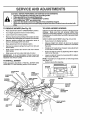
FRONT-TO-BACK ADJUSTMENT (See Figs. 25 and 26) IMPORTANT: DECK MUSTBE LEVELSIDE-TO-SIDE. 1F
THE FOLLOWING FRONT-TO-B,_CK ADJ._IS.TMENT IS_,
NECESSARY, BE SURE TO ADJUST BOTH'_'R'_R'FEINKS*
EQUALLY SO MOWER WILL STAY LEVEL SIDE*TO-SIDE.
To obtain the best cutting results, the mower housing
should be adjusted so the front isapproximately 1/8" to 1/2"
lower than the rear' when the mower is in its highest
position°
Check adjustment on right side of tractor. Measure distance "F' directly in front of and behind the mandrel at
bottom edge of mower housing as shown°
•
Before making any necessary adjustments, checkthat
both front links are equal in length.
•
If links are not equal in length,adjust one link to same
length as other link,,
° To lowerfront of mower housirrg, loosen nut"G" on both
front links an equal number of turns.
•
When distance "F" is 1/8" to 1/2" lower at front than
rear, tighten nut"H" against trunnion on both front links,
•
To raise front of mower housing, loosen nut "H" from
trunnion on both front links. Tighten nut "G" on both
front links an equal number of turns.
° When distance "F" is 1/8" to 1/2" lower at front than
rear', tighten nut "H" against trunnion on both front
links.
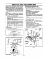
TO REPLACE
MOWER DRIVE BELT
MOWER DRIVE BELT REMOVAL (See Fig_ 27) ,
Park tractor on a level surface. Engage parking brake.
•
Remove four' screws from L,H. mandrel cover and
remove covet.
°
Roll belt over the top of L_H. mandrel pulJey,,
°
•
Remove belt from electric clutch pulley_
Remove belt from idler pulleys.
°
Remove any dirt or grass clippings which may have
accumulated around mandrels and entire upper deck
surface.
°
Check primary idler arm and two idlers to see that they
rotate freely,
Be sure spring is securely hooked to primary idler arm
and bolt in mower housing°
•
MOWER DRIVE BELT INSTALLATION (See Fig. 27) •
install belt in both idlerso Make sure belt is in both belt
keepers at the idlers as shown.
= Install new belt onto electric clutch pulley.
°
Roll belt into upper' groove of LH. mandrel pulley.
•
Carefully check belt routing making sure belt is in the
grooves correctly and inside belt keepers.
Reassemble L.H, mandrel cover'.
°
NOTE: Each full turn of nut "G" will change dim. "F" by
approximately 3/8".
•
Recheck side-to-side adjustment.
LH.
MANDREL
COVER
SPRING
IDLER
PULLEYS
PRIMARY
IDLER
ARM
_[i
.pTtt
ELECTRIC
CLUTCH
PULLEY
GROUND LINE
| r
////////////////////////////////////////
FIG. 25
BOLT IN
MOWER
HOUSING
BOTH FRONT LINKS SHOULD BE EQUALIN LENGTH
MANDREL
MOWER
DRIVE BELT
O
BELT
KEEPER
FIG. 27
FRONT LINKS
FIG. 26
20
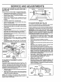
RV CE AND ADJUSTMENTS
TO REPLACE
(See Fig. 28)
MOWER BLADE DRIVE BELT
....
Park the tractor on level surface. Engage parking brake+
•
Remove mowerdrive belt (See'70 REPLACE MOWER
DRIVE BELT" in this section of this manual).
•
Remove mower (See "TO REMOVE MOWER" in this
section of this manual).
•
Remove four screws from Roll+ mandrel cover and
remove cover° Unhook spring from bolt on mower
housing+
•
Carefully roll belt off R.H. mandrel puIley+
°
Remove belt from center mandrel pulley, idler pulley,
and L+H. mandrel pulley°
°
Remove any dirt or grass which may have accumulated around mandrels and entire upper deck surface.
•
Check secondary idler arm and idler to see that they
rotate freely°
°
Be sure spring is hooked in secondary idler arm and
sway-bar bracket.
•
Install new belt in lower groove of Loll+mandrel pulley,
idler pulIey, and center mandrel pulley as shown.
•
RollbeltoverR.H. mandrelpulley° Make sure belt is in
all grooves properly.
°
Reconnect spring to bolt in mower housing and reinstall R.H+mandrel cover.
°
Reinstall mower to tractor (See "INSTALL MOWER
AND DRIVE BELT" in the Assembly section of this
manual).
°
Reassemble mower drive belt (See "TO REPLACE
MOWER DRIVE BELT" in this section of this manual).
L.H.
MOWER BLADE
MANDREL\\
DRIVE B
NYLON LOCKNUT (3)
FIG. 29
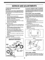
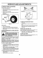
TO ADJUST BRAKE (See Fig, 30)
Your tractor is equipped with an adjustable brake system
which is mounted on the left side of the transaxle.
If tractor requires more than six (6) feet stopping distance
at high speed in highest gear, then brake must be adjusted°
IMPORTANT" DO NOT OVER TIGHTEN BRAKE. WHEN
DEPRESSING CLUTCH BRAKE PEDAL, THE MOTION
DRIVE BELT MUST STOP MOV1NG (DECLUTCH FROM
ENGINE PULLEY) BEFORE BRAKE ENGAGES.
IMPROPER ADJUSTMENT WILL CAUSE HARD SHIFTING
AND EXCESSIVE WEAR TO BRAKE LINING°
°
Park and turn off the tractor on a level surface° Place
gear shift lever in neutral (N) position. Disengage
parking brake and be sure tractor does not roll in either
direction.
° Lower mower deck (if installed on tractor').
° Snap outaccess hole coveron leftside of tractor above
footrest.
° Loosen jam nut at clevis which will allow brake rodto be
rotated°
= With pliers, from underside of frame, unscrew brake
rod from clevis four (4) to six (6) full turns.
° Starttractorwithgearshiftleverin
neutral(N) position.
° Slowly depress clutch/brake pedal to the point where
the motion drive belt stops moving. Hold clutch/brake
pedal in this position and engage parking brake° If belt
begins to move after engaging parking brake, reset
parkingbrake by depressing clutch/brake pedal slightly
to next notch on parking brake.
° Stop engine_ Screw brake rod back into clevis until
clevis pin is against rear edge of slot in brake arm, Do
not over tighten (see "IMPORTANT" above).
° Tighten jam nut against clevis°
°
Replace access hole cover.
°
Road test tractor for proper stopping distance and
declutching as stated above° Readjust ifnecessary. If
proper adjustment cannot be attained, further mainte+
nance is necessary. Contact your nearest authorized
service center!department°
CENTER
MANDREL
MANDREL
COVER
SECONDARY
IDLER ARM
SWAY-BAR
BRACKET
IDLER
PULLEY
FIG, 28
TO ADJUST
ATTACHMENT
CLUTCH
(See Fig. 29)
The electric clutch should provide years of service, The
clutch has a built-in brake that stops the pulley within 5
seconds, Eventually, the internal brake will wear which
may cause the mower blades to not engage, or, to not stop
as required+ Adjustments should be made byyour nearest
authorized service center!department+
o Make sure attachment clutch and ignition switches ar+e
in "OFF" position.
° Adjust the three nylon Iocknuts until space between
clutch plate and rotor measures .012" at all three stot
locations cut inside of brake plate.
NOTE-" After installing a new electric clutch, run tractor at
full throttle and engage and disengage electric clutch 10
cycles to wear in clutch plate.
BRAKE PLATE
FIG. 30
21
rllll
AND ADJUSTMENTS
"Hill
IllUlIII
IIIIIIIIIII IIIIIIIIIIIIIII
TO REPLACE
(See Fig. 31)
.........................
IIIIIJ,J,!!!,,
,!,!,,,,,!,,,,!,,
TO ADJUST STEERING WHEEL ALIGNMENT
MOTION DRIVE BELT
Park the tractor on level surface. Engage parking brake.
Forease of service there is a beltinstallationguide decal on
bottomof leftfootresL Itis not necessaryto removemower_
If steering wheel crossbars are not horizontal (left to right)
wheh wheels are positioned straight forward, remove steeringwheel and reassemble per instructions inthe Assembly
section of this manual
BELT REMOVAL -
FRONT WHEEL TOE-IN ADJUSTMENT
•
Front wheel toe-inis requiredfor proper steering operation.
Toe-in was set at the factory and adjustment should not be
necessary. If parts in the front axle or steering mechanism
have been replaced or' damaged, check toe-in and adjust
if necessary°
•
Raise hood and disconnect BLACK (grounding) battery cable.
Set parking brake (to get belt slack),
•
Remove mower drive belt from electric clutch pulley
only (See 'TO REPLACE MOWER DRIVE BELT" in
this section of this manual)_
°
°
Roll motion drive belt off transaxle pulley.
Roll belt off clutching idler pulleys, then off engine
pulley and front V-idler pulley.
Pull belt out of all belt keepers.
BELT INSTALLATION -
TO CHECK TOE-IN (See Fig° 32) ° Position front wheels straight ahead.
o
Measure distance between wheels at front and rear of
tires (dimensions "A" and "B").
°
Front dimension "A" should be 1/8" to 1/4" less than
rear dimension "B".
°
TO ADJUST TOE-IN (See Figs. 32 and 33) -
°
Place V part of belt into grooves on engine pulley and
front V-idler, making sure to route belt inside of belt
keepers.
•
Put beltcomingfromV-idlerabove
midspan belt keeper,
then onto clutching idler pulleys as shown.
°
Make sure %" part of belt engages "V" idler.
•
Place belt around transaxle pulley, beginning at top.
"V" part of belt should engage transaxle pulley.
Place long lower section of belt through loop in midspan
belt keeper.
Check to be sure belt is on proper side of all belt
keepers°
Reinstall mower drive belt onto electric clutch pulley.
°
•
°
o
Loosen jam nuts at adjustment sleeves on tie rod.
°
Adjust tie rod until dimension "A" is 1/8" to 1/4" less than
dimension "B".
°
Tighten jam nuts securely.
f_
B
FRONT OF TRACTOR
°
Release parking brake.
IMPORTANT." CHECK BRAKE ADJUSTMENT_
A
_"
FIG. 32
TRACTOR V-BELT DRIVE SCHEMATIC
VIEWED FROM LH. SIDE OF TRACTOR
ADJUSTMENT
SLEEVES
CLUTCHING
IDLER
CLUTCHING
FLAT IDLER
ENGINE
PULLEY
\
BELT
ABOVE BELT _
V-IDLER
KEEP!
JAM NUTS
KEEPER
BELT
TWISTS
BELT
KEEPER
FIG. 33
TRANSAXLE
PULLEY
FRONT WHEEL CAMBER
The front wheel camber isnot adjustable on your tractoL tf
damage has occurred to affect the front wheel camber,
contact your nearest authorized service center/department.
AS VIEWED FROM BOTTOM
FIG. 31
22
SERVICE AND ADJUSTMENTS
TO REMOVE
WHEEL FOR REPAIRS
FRONT WHEEL (See Fig. 34) o Block up axle securely°
•
Removeaxle cover, retainingring and washersto ailow
wheel removal°
°
o
Repair tire and reassemble.
Replace washers and snap retaining ring securely in
axle groove.
°
Replace axle cover°
"POSITIVE"
(+)
"NEGATIVE"
(-)
HERS
RETAINING
AXLE
COVER
FIG, 35
TO REPLACE
FIG. 34
REAR WHEEL -
HEADLIGHT
BULB
-
Raise hood.
°
Pull bulb holder out of the hole in the backside of the
grill.
•
Replace bulb in holder and push bulb holder securely
back into the hole in the backside of the grill
Close hood.
o
Block rear axle securely.
o
Remove five (5) hub bolts to allow wheel removal
o
o
Repair tire and reassemble. Replace and tighten hub
bolts secu rely.
INTERLOCKS
AND RELAYS
Loose or damaged wiring may cause your tractor to run
poorly, stop running, or prevent it from starting.
TO START ENGINE WITH A WEAK BATTERY
(See Fig. 35)
•
CAUTION: Lead-acid batteries generate explosivegases. Keep sparks, flame
and smoking materials away from batteries. Always wear eye protection
when around batteries.
Check wiring. See electrical wiring diagram in the
Repair Parts section of this manual°
TO REPLACE
FUSE
Replace with 30 amp automotive-type plug_in fuse° The
fuse holder is located behind the dash,,
If your battery is too weak to start the engine, it should be
recharged°
if "jumper cables" are used for emergency
starting, follow this procedure:
IMPORTANT:
YOUR UNIT IS EQUIPPED
WITH A 12
VOLT NEGATIVE GROUNDED
SYSTEM,. THE OTHER
VEHICLE
MUST ALSO BE A 12 VOLT NEGATIVE
GROUNDED SYSTEM.
DO NOT USE YOUR TRACTOR
BATTERY TO START OTHER VEHICLES..
TO ATTACH JUMPER CABLES ° Connect each end of the RED cable to the POSITIVE
(+) terminal of each battery, taking care not to short
against chassis.
° Connect one end of the BLACK cable to the NEGATIVE (-) terminal of fully charged battery,.
° Connect the other end of the BLACK Cable to good
CHASSIS GROUND, away from fuel tank and battery.
TO REMOVE CABLES, REVERSE ORDER
= BLACK cable first from chassis and then from the fully
charged battery.
o RED cable last from both batteries.
23
illlUlllllllllllllll
i
IIIIILIIIIIIIIllLIIIII
Illllll
,I
X
X
.......................................
SERVICE AND ADJUSTMENTS
TO ADJUST ATTACHMENT
(See Fig. 36)
LIFT SPRING
•
While holdingspring bushing with wrench, loosen jam
nut.
•
Turn adjustment bolt clockwise to extend spring and
reduce tift effort for heavier attachments.
•
Turn adjustment
tachments.
bolt counterclockwise
ADJUSTMENT
BOLT
SPRING BUSHING
for lighter atJAM
°
Retighten jam nut against spring bushing.
IMPORTANT:
DO NOTADJUST
FOR MAXIMUM SPRING
TENSION WHEN USING LIGHT ATTACHMENTS
SUCH
AS A MOWER° ADJUST LIFT LEVER SPRING TO AID IN
LIFTING ATTACHMENT.
DO NOTOVERPOWER
SPRING.
WHEN REMOVING
ATTACHMENT,
ALWAYS ADJUST
SPRING TENSION TO ITS LOWEST POSITION.
o
NUT
ATTACHMENT
LIFT SPRING
f
FIG. 36
TO REMOVE HOOD AND GRILL ASSEMBLY
(See Fig. 37)
°
Raise hood.
°
•
Unsnap headlight wire connector_
Stand infront oftractor. Grasp hood at sides, tilttoward
engine and lift off of tractor.
,
To replace, reverse above procedures.
WIRE
CONNECTION
HOOD
FIG. 37
24
ERVICE AND ADJUSTMENTS
i,
ENGINE
ACCELERATION
TO ADJUST THROTTLE
(See Fig, 38 & 39)
CONTROL
=
CABLE
The throttle control has been preset at the factory and
adjustment should not be necessary. Check adjustment as
described below before loosening cable° If adjustment is
necessary, proceed as follows:
°
With engine not running, move throttlecontrol lever to
fast 0 position.
o
Checkthat speed controllever isagainst stopscrew. If
it is not, loosen casing clamp screw and pull throttle
cable until lever isagainst screw° Tighten clamp screw
securely.
TO ADJUST
CARBURETOR
TEST -
Move throttle control lever from _low 0 to fast 0
position, If engine hesitates or dies,_.turn Idle mixture
screw out (counterclockwise)
1/8 turn, Repeat test and
continue to adjust, if necessary, until:engine
accelerates smoothly..
High speed stop is factory adjusted. Do not adjust-damage
may result.
IMPORTANT;
NEVER TAMPER
WITH THE ENGINE
GOVERNOR,
WHICH IS FACTORY SET FOR PROPER
ENGINE SPEED. OVERSPEEDING
THE ENGINE ABOVE
THE FACTORY
HIGH
SPEED
SETTING
CAN BE
DANGEROUS°
IFYOU THINKTHE ENGINE-GOVERNED
HiGH SPEED NEEDS ADJUSTING,
CONTACT
YOUR
NEAREST
AUTHORIZED
SERVICE
CENTER/
DEPARTMENT, WHICH HAS PROPER EQUIPMENT AND
EXPERIENCE
TO
MAKE
ANY
NECESSARY
ADJUSTMENTS..
(See Fig. 40)
The carburetor has been present at the factory and adjustrnentshould notbe necessary. However, minoradjustment
may be required to compensate for differences in fuel,
temperature, altitude or load. If the carburetor does not
need adjustment, proceed as follows:
CASING
In general, turning the adjusting needles in (clockwise)
decreases the supply of fuel to the engine giving a ieaner
fuel/air mixture. Turning the adjusting needles out (counterclockwise) increases the supply of fuel to the engine
giving a richer fue!/air mixture°
IMPORTANT: DAMAGE TO THE NEEDLES AND THE
SEATS IN CARBURETOR MAY RESULT IF SCREW tS
TURNED IN TOO TIGHT°
STOP SCREW
SPEED CONTROL
LEVER
THROTTLE
CONTROL
CABLE
PRELIMINARY SETTING o
Be sure you have a clean air filter, and the throttle
control cable is adjusted properly (see above),,
.
With engine off turn idle fuel adjusting needle in (clockwise) closing it finger tight and then turn out (counterclockwise) 1-1/4 turns,,
FIG. 38
STOP
SCREW
°
Turn main fuel adjusting needle in (clockwise) closing
finger tight and then turn out (counterclockwise) 1 turn,,
FINAL SETTING -
°
Start engine and allow to warm for five minutes. Make
final adjustments with engine running and shift/motion
control lever in neutral (N) position,,
.
With throttle control lever in fast 0 position, turn main
fuel adjusting needle in (clockwise) until engine begins
to die then turn out (counterclockwise) until engine
runs rough. Turn needle to a point midway between
those two positions.
Idle sneed settina- With throttle control lever in slow 0
position, engine'should idle at 1400 RPM if engine
idles too slow or fast, turn idle speed adjusting screw in
or out until correct idle is attained°
°
°
°
SPEED
CONTROL
LEVER
FIG. 39
.........
o
_
_
ADJUSTING
....
idle fuel needle setting - With throttle control lever in
slow () position, turn idle fuel' adjusting needle in
(clockwise) until engine begins to die and then tfamout
(counterclockwise) until engine runs rough. Turn needle
to a point midway between those two positions.
Recheck idle speed. Readjust if necessary.
_
ADJUSTING
NEEDLE
25
FIG. 40
ENGINE
Immediately prepare your tractor for storage at the end of
the season or if the tractor will not be used for 30 days or
more.
FUEL SYSTEM
IMPORTANT:
IT IS IMPORTANT
TO PREVENT GUM
DEPOSITS
FROM FORMING
IN ESSENTIAL
FUEL
SYSTEMPARTS SUCH AS CARBURETOR, FUEL FILTER,
FUEL HOSE, OR TANK DURING STORAGE.
ALSO,
EXPERIENCE
INDICATES
THAT ALCOHOL BLENDED
FUELS (CALLED GASOHOL OR USING ETHANOL OR
METHANOL) CAN ATTRACT MOISTURE WHICH LEADS
TO SEPARATION AND FORMATION
OF ACIDS DURING
STORAGE.
ACIDIC GAS CAN DAMAGE THE FUEL
SYSTEM OF AN ENGINE WHILE IN STORAGE.
CAUTION: Never store the tractor with
gasoline In the tank inside a building
where fumes may reach an open flame
or spark. Allow the engine to cool
before storing in any enclosure.
......................
ii
I
I
II
IUU
I
TRACTOR
Remove mower from tractor for winter storage. When
mower is to be stored for a period of time, clean it thor_
oughly, remove all dirt, grease, leaves, etco Store in a
clean, dry area°
•
•
Clean entiretractor (See "CLEANING" in the Customer
Responsibilities section of this manual),
Inspect and replace belts, if necessary (See beft replacement instructions in the Service and Adjustments
section of this manual),
•
Lubricate as shown in the Customer Responsibilities
section of this manual,
•
Be sure that all nuts, bolts and screws are securely
fastened, Inspect moving parts for damage, breakage
and wear_ Replace if necessary_
o
Touch up all rusted or chipped paint surfaces; sand
lightly before painting,
o
°
°
°
Fully charge the battery for storage,
°
After a period of time in storage, battery may require
recharging,
To help prevent corrosion and power leakage during
tong periods of storage, battery cables should be
disconnected and battery cleaned thoroughly (see'q'O
CLEAN BATTERY AND TERMINALS in the Customer Responsibilities section of this manual),
°
.
Start the engine and let it run until the fuel lines and
carburetor are empty,
Never use engine or carburetor cleaner products inthe
fuel tank or permanent damage may occur.
;"
Use fresh fuel next season,
NOTE: Fuel stabilizer is an acceptable alternative in
minimizing the formation of fuel gum deposits during storage. Add stabilizer to gasoline in fuel tank or storage
container, Always follow the mix ratiofound on stabilizer
container. Run engine at least 10 minutes after adding
stabilizer to allow the stabilizer to reach the carburetor. Do
not drain the gas tank and carburetor if using fuel stabilizer.
ENGINE OIL
Drain oil(with engine warm) and replace with clean engine
oilo (See "ENGINE" in the Customer' Responsibilities
section of this manual).
BATTERY
-
Drain the fuel tank°
CYLINDERS
•
Remove spark plug(s).
°
Pour' one ounce of oil through spark plug hole(s) into
cylinder(s).
Turn ignition keyto"START" position for a few seconds
to distribute oil,
•
=
After cleaning, leave cables disconnected and place
cables where they cannot come in contact with battery
terminals,
Replace with new spark plug(s)_
OTHER
•
Be sure battery drain tube is securely attached,
•
Do not store gasoline from one season to another,
•
If battery is removed from tractor for storage, do not
store battery directly on concrete or damp surfaces,
°
Replace your gasoline can if your can starts to rust_
Rust and/or dirt in your gasoline will cause probtems,
°
If possible, store your tractor indoors and cover it to
give protection from dust and dirt,
° Cover your tractor with a suitable protective covet'that
does not retain moisture. Do not use plastic. Plastic
cannot breathe which allows condensation to form and
will cause your' tractor to rusL
IMPORTANT: NEVER COVER TRACTOR WHILE ENGINE
AND
26
EXHAUST
AREAS
ARE
STILL
WARM.
27
TROUBLESHOOTING
POINTS
PROBLEM
CAUSE
CORRECTION
Will not start
I.
2_
3,
4.
5.
6,
7
1_
2.
3,
4,
5,
6
7
Outof fuel.
Engine not "CHOKED" pmpedy
Engine flooded.
Bad spark plug
Dirty air filter,,
Dtrty fuet filter_
Water In fuel
Filt fuel tank.
See "TO START ENGINE" in Operation section,
Walt severed minutes before attempting to start,
Reptace spark plug.
Clean/replace air fitter,.
Replace fuel filter,,
Drain fuel tank and carburetor, refill tank with fresh
gasofine and replace fuel fffter.
Check aU wiring,,
Contact an authodzed service center/department.
Contact an authorized service center/department,
8
9,
10.
Loose or damaged w]dng
Carburetor out of adjustment
Engine valves out of adjustment
8,
9,
10
Hard to start
1_
2
3.
4.
5,
6.
7,
8
Dirty air filter.
Bad spark plug
Weak or dead battery°
Dirty fuel filter.
Stale or dirty fuet.
Loose or damaged w]dng
Carburetor out of adjustmenL
Engine valves out of adjustment
1_
2,
3,,
4.
5.
6_
7.
8,
Clean/replace air filter,,
Replace spark plug.
Recharge or replace battery.
Replace fuel filter,,
Drain fuel tank and refill with fresh gasoZlne.
Cheek al_wtdng
Contact an authorized service center/department,.
Contact an authorized service eenter/departmenL
Engine will not turn over
I.
2
3
4
Clutch/brake pedal not depressed
Attachment dutch Is engaged.
Weak or dead battery.
Blown fuse.
5
6,
7o
8.
9,
Corroded battery terminals.
Loose or damaged wiring
Faulty Ignition switch.
Faulty soienofd or starter_
Faulty operator presence switch(es),
1_,
2,
3,
4_
5.
6.
7_
8,
9,
Depress clutch/brake pedal.
Disengage attachment clutch
Recharge or replace battery,
Replace fuse,
Clean battery terminals,
Check alt w]dng_
Check/replace Ignition switch,
ChecPJreplace solenoid or starter_
Contact an authorized service centeddepartment,
Engine clicks but will not
start
1.
2
3,
4o
Weak or dead battery,
Corroded battery terminals,
Loose or damaged wtdng.
Faulty solenoid or starter,
1.
2.
3
4.
Recharge or reptace battery,
Clean battery terminals.
Check elf wiring.
Check/replace solenoid or starter,
Loss of power
1_
2,,
3.
4,
5o
6,,
7,
8.
9,
Cutting too much grass/too fast
Throttle tn "CHOKE" position.
Build-up of grass, reaves and trash under mower
Dirty air fl_ter.
Low oil lavei/dtrty oft,
Faulty spark plug,
Dirty fuel filter_
Stale or dirty fuel
Water tn fuel.
1.
2,
3.
4
5,
6,,
7.
8,
9,,
Set in "Higher Cut" position/reduce speed
Adjust throttle control,
Clean underside of mower housing,.
Clean/replace air filter,,
Check oil level/change oil
Clean and regap or change spark plug,
Replace fuel filter,
Drain fuel tank and refill with fresh gasoline.
Draln fuel tank and carburetor, refill tank with fresh
10,
11,,
12_
13,
14.
15.
Excessive vibration
Spark plug wire loose,.
Dirty engine air screen/fins.
D_rty/clogged muffler.
Loose or damaged wiring°
Carburetor out of adJustmenL
Engine valves out of adjustment,
t_
2.
wom, bent or loose blade.
Bent btade mandrel.
3
Looseldamaged
part(s),
28
10
11,,
12.
13_
14.
15.
gasoline and replace fuel filter,.
Connect and tighten spark plug wire_
Clean englne air screenif_ns.
Clean!replace muffie_
Check all wtdng.
Contact an authorized service centertdepartment
Contact an authodzed service center/departmenL
1.
2.
3o
Replace blade,. Tighten blade bolt,.
Replace btade mandrel
Tighten loose part(s), Replace damaged parts,
POINTS
i
PROBLEM
CAUSE
,ll,,ll,l,ll,,lll,,i,,_.ju,,i,,, i
CORRECTION
±1
i
_1 _r
Engine continues to run
when operator leaves seat
with attachment clutch
engaged
l
Faulty operator-safeiy
presence control system
Poor cut - uneven
1,,
2.
3,
4,,
Wom, bent or loose blade
Mower deck net level,
Buildup of grass, leaves, and trash under mower.
Bent blade mandrel
5.
Clogged mower deck vent hotes from buildup of
grass, leaves, and trash around mandrels.
Mower blades will not
rotate
1,, ObstnJctlon {n clutch mechanism.,
2, Worn/damaged mower drive bell
3
Frozen Idler pulley.
4. Frozen blade mandrel.,
Poor grass discharge
1,
2.
3.
4.
Engine speed too slow.,
Travel speed too fast.
Wet grass.
Mower deck not level
5.,
6.
7.,
8o
Low/uneven tire air pressure,
Worn, bent or loose blade.
Buildup of grass, leaves and trash under mower°
Mower drive belt worn
9. Blades improperly Installed.
10. Improper blades used,,
11o Clogged mower deck vent holes from buildup of
grass, leaves, and trash around mandre{so
Headlight(s) not working
(if so equipped)
i
i,,
Battery wtll not charge
Engine "backfires"
when turning engine
"OFF"
1,. Check wiring, switches and connecltons
If not
corrected, contact an authorized service center/
department.
1.
2.
Replace blade,. Tighten blade bolt
Level mower deck
3,
4.
5
C{ean underside of mower housing.
Replace blade mandrel°
Clean around mandrels to open vent holes,
1.
Remove obstruction,
2,,
3,
4.
Replace mower ddve belt,,
Reptace idler pul{ey,
Replace blade mandrel
1,,
2.
3,
4.
5.
6
7o
8,
9.
10,,
11_,
Place throttle control in "FAST" position
Shift to slower speed.
Allow grass to dry before mowing,
Level mower deck.
Check tires for proper air pressure.
Replace/sharpen blade. Tighten blade boll
Clean underside of mower houstng,
Replace mower drive belto
Reinstall blades sharp edge down.
Replace with blades listed {n this manual.
Clean around mandrels to open vent holes
1,,
2.,
3,
4,
5_
Switch is "OFF",
Bulb(s) burned out,,
Faulty fight switch,,
Loose or damaged wtdng.
Blown fuse,
1,
2,
3r
4,
5.,
Turn switch "ON"
Replace bulb(s).
Check/replace light sw]tch_
Check wldng and cennecttons_
Replace fuse
1,,
2,
Bad battery ceI{(s)
Poor cable connections
3,
4,,
Faulty regulator (if so equipped),
Faulty alternator,
1_,
2.
3.,
4.,
Replace battery
ChecWclean all connections
Replace regulator
Replace alternator,
1.
Engine throttle control not set at "SLOW"
position for 30 seconds before stopping engine,
1.
Move throttte conlrol to "SLOW" position and al{ow
to Idle for 30 seconds before stopplng engine,
i
29
18 HP 44" TRACTOR - MODEL NUMBER 917.255980
SCHEMATIC
BATTERY
RED
FUSE 30 AMP,
AMMETER
WHITE
'
IC
Dl
_____
'
-1---'
i
I@',
1
STARTER
"
J
SOLENOID
F
_
t1
CLUTCH / BRAKE
(PEDAL UP)
l
IGNITION
"_
SWITCH
B
t_
RED ,,
!
E_
(_,
ELECTRIC CLUTCH
| kJ'_"_
I
I
L ......
|
.........
PTO
(DISENGAGED)
t_
AO
=_
RED
T
! ........
SEAT SWITCH
(NOT OCCUPIED)
BLACK
._D
86 I
,__,
t 87
"I
....
l-'-
l__,
8LACK,,
lw
h
I
t 85
_
BLACK.
30
'[ 0.._v I--,_'
OPERATOR PRESENCE
RELAY
BLACK
_|
GROUNDING
CONNECTOR
_LA°_'
O
d
BLACK
(_
WIRING
IGNITION
UNIT
_
SPARK
PLUGS
__--"_
CHARGING SYSTEM OUTPUT
t5 AMP DC O :3600 RPM
RED
28 VOLT5 AC @ :]600 RPM
(REG ULATOR DISCO NNECTED}
"30
RELAY
HEADLIGHT
SWITCH
(OFF)
I
HEAD LIGHTS
NON-REMOVABLE
CONNECTIONS
REMOVABLE
CONNECTIONS
IGNITION SWITCH
POSITION
ON
START
B+L
B+ S
CIRCUIT
B+A,C+F
CLIPS
cupsWEREREMO.VED
FOR
M +G
.
PosmoN
ON
WIRING INSULATED
CIRCUIT
OFF
P'fO SWITCH
........
SERVICING OF UNIT, THEY
NOTE:
INSULATED
SHOULDIF WIRING
BE REPLACED
TO
PROPERLY SECURE YOUR WIRING
30
cD
_F
U
"u
I1
I]
_ __1
ERA
/';
REPAIR PARTS
18 HP 44" TRACTOR
- - MODEL
NUMBER
917.255980
DECALS
18
6 3
15
7 15
4
13
8\
8
13
7
10
9
\
11
KEY
NO.
PART
NO.
'I
2
3
4
5
6
7
8
9
10
11
136794
138591
138042
138O43
138264
133644
138048
128538
128314
137537
4900J
I2
KEY
NO.
DESCRIPTION
12
13
14
15
17
18
19
23
---
Decal, Operating Instruction
Decal. Grill GT 6000 USA BIack
Decal Hood, Craftsman, RH
Decal Hood, Craftsman, LH
Decal .Grille, Craftsman
Decal Maintenance
Decal Side Panel
Decal Side Panel
Decal Fender, Craftsman
Decal Caution
Decal Clutch/Brake
WHEELS & TIRES
KEY
NO.
1 _"'"_-_""-a
1
2
3
3
7
4
5
5
8
6
7
8
PART
NO.
138435
I05567X
'139346
138276
138834
132266
138047
106202X
137979
137980
PART
NO.
59192
65139
122974X
3635R
8134H
7154J
106230X
105588X
278H
9040H
104757X
136327
DESCRIPTION
Decal, V-Belt Drive Schematic
Decal, Chassis, 6 Speed/44"
Decal, V-Belt Schematic
Decal Hood Insert Hd GT
Decal, Dash
Decal, Insert Strg
Decal, Battery
Reflector, Taillight
Manual, Owner's (Eng)
Manual, Owner's (Span)
DESCRIPTION
Cap, Valve, Tire
Stem, Valve
Rim Assembly, Front
Rim Assembly, Rear
Tube, Front (Service Item Only)
Tube, Rear (Service Item Only)
Tire, Front
Tire, Rear
Fitting, Grease (Front Wheel Only)
Beating, Flange (Front Wheel Only)
Cap, Axle (Front Wheel Only)
Cover, Axle (Rear Wheel Only)
NOTE: All component dimensions given in U.So inches
I inch = 25.4 mm
31
REPAIR PARTS
18 HP 44" TRACTOR-
MODEL NUMBER 917.255980
ELECTRICAL
A
B
C
_12
_13
_14
_16
52
_17
t
29
1
1
3
I
39
/
/
/
/
I
I
l
/
l
/
I
\
t
1
t
#
#
/
/
!
t
32
REPAIR PARTS
18 HP 44" TRACTOR-
MODEL
NUMBER
917,255980
ELECTRICAL
NO.
NO.
1
2
3
4
6
7
8
9
10
11
12
!3
14
109310X
4406R
123620X
124211X
110712X
121537X
7603J
7697J
109596X
138406
10090400
STD541225
17720408
15
16
104445X
71031008
'17
18
"f9
20
21
24
26
27
28
29
37
39
40
41
42
43
44
45
46
48
49
50
51
52
7395100O
135665
137424
4152J
108824X
121080X
4021J
4022J
4799J
131563
7224O460
123198X
t02476X
STD522507
STD551025
STD541025
STD551125
127441X
121305X
109748X
121264X
122822X
19171216
11150400
DESCRIPTION
Key, Ignition
Switch, Ignition
Cover, Switch Key
Nut, Ignition
Switch, Light
Battery
Tray, Battery
Tube, Drain
Clamp, Hose
Solenoid
Washer, Lock 1/4
Nut, Hex Jam 1/4-20
Screw, Hex Washer Head, Thread
Cutting 1/4-20 x 1/2
Switch, Intlk CI Grd Gry 2 Term
Screw, Hex Washer Head
#10-32xl/2
Nut, Keps #10-32
Diode Asmo, Heavy Duty
Harness, Ignition
Bulb, Headlight
Fuse
Cable, Ground
Switch, P.T.O.
Nut, Hex 1/2-28 Unef
Cable, Battery
Cover, Terminal
Bolt, Carriage 1/4-20 x 7-i/2
Nut, Wing 1/4-20
Guard, Terminal
Bolt, Hex 1/4-20 x 3/4
Washer 9/32 x 5/8 x 16 Gao
Nut, Hex 1/4-20
Washer, Lock 1/4
Harness, Light Socket
Switch, Plunger
Relay, Operator Presence
Caps, Battery
Ammeter
Washer 17/32 x 3/4 x 16 Ga.
Washer, Lock, Int. Tooth
NOTE: All component dimensions given in U.So inches
1 inch = 25_4 mm
33
REPAIR PARTS
18 HP 44" TRACTOR - MODEL NUMBER 917.255980
CHASSIS
AND ENCLOSURES
14
18
15
53
64 15
93
30
95
66
_F"'"-'_ 26
52
17
21
69
21
\
i_'
43
17
93
20
19
25
44
4
36
70
40
86
21
94
2O
39
34
REPARR PARTS
18 HP 44" TRACTOR
CHASSIS
- MODEL
NUMBER
917.255980
AND ENCLOSURES
KEY
NO.
PART
NO.
1
2
3
4
5
6
7
8
9
10
11
12
13
14
15
16
17
18
19
20
21
22
23
24
25
26
27
28
29
30
31
32
33
34
35
36
37
38
39
40
41
42
138597
7982J
136671X459
73800700
136696
137251
17720408
140229
108067X
19092016
137270
137269
137271
136673X459
136374
121794X
17490612
136373X428
19131312
74760616
73800600
136670X459
121045X
105464X459
17490612
17490512
121046X
105465X459
138193
137143X013
137556
136742
136741
136963
19111116
74780512
121642X459
19091216
136961
136962
74760408
72140608
KEY
NO.
DESCRIPTION
Rail, Frame RH
Drawbar, Gt
Panel Asm., Side LH
Nut, Lock Hex 7/16 Unc
Dash, Plastic Black
Dash Asmo, Lower
Screw, Thd Cut 1/4-20 x 1/2
Support, Battery
Nut, Pal
Washer 9i32x1-1i4x16Gao
Rivet, Ratchet Male
Washer, Nylon
Rivet, Ratchet Female
Hood Asm., Pnt
Lens, Bar Clear
Cover, Access
Screw, Thdrol 3/8-16 x 3/4
Grille
Washer 13/32 x 13/16 x 12 Ga.
Bolt, Fin Hex 3/8-16 x I
Nut, Lock Hex W/Wsh 3/8-16 Unc
Panel Asm., Side RH
Panel, Dash Side RH
Footrest, RH
Screw, Thdrol 3/8-16 x 3/4
Screw, Thdrol 5/16_18 x 3/4
Panel, Dash Side LH
Footrest, LH
Bracket, Support Dash
Saddle, StkscrVgt
Brace, Support Steering
Bracket Asm., Frame Pi"votLh
Bracket Asm., Frame Pivot Rh
Bracket, Engine Support Rear
Washer 11/32x11116x16Ga.
Bolt, Fin Hex 5/16-18 x 3/4
Fender, PnL
Washer 9/32 x 3/4 x 16 Ga_
Bracket, Axle Front
Bracket, Support Axle!Engine
Bolt, Fin Hex 1/4-20 Unc x 1/2
Bolt, Carriage 3/8-i6 x I
43
44
45
46
48
49
50
52
53
54
56
57
58
59
60
62
63
64
65
66
67
69
70
72
73
77
78
84
85
86
88
90
91
92
93
94
95
96
97
PART
NO.
136939
136940
138460
10040400
136814
136813
136575
73800500
137304
126470X
138461
73510400
137113
74180412
72140610
72110608
19t31614
10040600
73220600
105466X
140737
140022
137159
74180512
74780616
137308
17720408
138952
t20404X
74760716
10040700
11050600
110893X
124557X022
17490608
100207K
105531X
8022J
137373
DESCRIPTION
Bracket, Spnsn Front Lh
Bracket, Spnsn Front Rh
Bracket Asm., Susp Chassis Rh
Washer, Lock Hvy Helical 1/4
Bracket Asm., Pivot Hood Lh
Bracket Asm. Pivot Hood Rh
Bracket, Chassis Front
Locknut, Hex W/Ins 5/16-18 Unc
Rod, Support Hood
Clip, Insulated
Bracket Asm., Susp Chassis Lh
Nut, Keps Hex 1/4-20
Bracket Asmo, Fende[
Screw, Mach Cr 1/4-20 x 3/4
Bolt, Carriage 3/8-16 x 1-'1/4
Bolt, Carriage 3/8-16 x 1 Gr,, 5
Washer 13/32 x 1 x 14 Ga.
Washer, Lock Hvy Htcl Spr 3/8
Nut, Fin Hex 3/8-16 Unc
Pad, Footrest
Guide, Belt T/A
Shield, Heat
Guide, Belt Mid Span
Screw, Mach Trhd 5/16-18 x 3/4
Bolt, Fin Hex 3/8-16 x 1 Gr,, 5
Shield, Front
Screw, Thd. Cut 1/4-20 x 1/2
Stop, Over Center Mower
Bracket, Support Transaxle
Bolt, Fin Hex 7/16-14 Unc x 1
Washer, Lock Hvy Hlcl Spr 7/t 6
Washer, Lock External Tooth 3/8
Rail, Frame Lh
Plate, Silkscreen Dash
Screw, Thdrol 3/8-16 x 1/2
Clip, Fuel Line
Push Nut, Nylon
Plug, Hole
Shield,
Heat,Engine
NOTE: All component dimensions given in U..S,.inches
1 inch = 25°4 mm
35
REPAIR PARTS
18 HP 44" TRACTOR - MODEL NUMBER 917.255980
GROUND
DRIVE
31
36
46
32
28
68
29
51
\
64
35
34
25
48
27
52
53
9
57
_23
67
1
57
7
69
3
36
51
REPAIR PARTS
18 HP 44" TRACTOR - MODEL NUMBER 917.255980
GROUND
DRIVE
KEY
NO.
PART
NO.
1
2
3
7
8
9
10
11
12
13
14
15
16
17
18
19
20
21
22
23
24
25
26
27
28
9858M1
2228M
7563R
135758
12000034
140080
214J
101122M
9204H
STD551125
STD541025
73530600
1913!614
7241J
7229J
1685H
STD533t07
72140405
633A109
106932X
74760614
19131316
STD551137
677A637
74370612
29
30
31
32
33
34
35
36
5308J
73610600
STD560907
100604K
5102J
124236X
137255
138364
DESCRIPTION
Key, Woodruff
Key, Woodruff
Washer, Thrust, Axle
Wheel Hub Assembly
Klip Ring
Bolt, Hub
Drum, Brake
Band, Brake
Locknut 1/2-20
Washer, Lock 1/4
Nut, Hex 1/4-20
Locknut 318-24
Washer 13/32 x I x 14 Gauge
Spring, Compression
Guide, Brake Rod
Locknut 5/16q8
Bolt, Carriage 5/18-18 x 3/4
Bolt, Carriage 1/4-20 x 5/8
Gearshift Lever Assembly
Knob
Bolt, Hex Head 3/84 6 x 7/8
Washer13/32 x 13/16x 16 Gauge
Washer, Lock 3/8
Bracket, Brake
Screw, Machine, Flat Head
3/8-16 x 3/4
Brake Rod
Nut, Hex 3/8-24
Pin, Cotter 3/32 x 3/4
Yoke
Pin, Clevis
Cap, Plunger
Rod, Parking Brake
Spring, Extension, Clutch
KEY
NO.
PART
NO.
37
38
39
40
41
42
43
44
45
46
47
48
49
50
5t
52
53
54
55
56
57
58
121749X
110895X
74321016
5304J
STD541410
8883R
STD522507
104601X
73680400
121358X
138228
72110614
191314'13
131494
73800600
139123
207J
138390
105706X
137153
105598X
73800500
59
60
6I
62
63
64
65
66
67
68
69
122253X
122268X
137524
STD551143
74760720
104375X
67609
t29962
19131312
5142H
136327
DESCRIPTION
Washer 25/32 x 1-1/4 x 16 Gauge
Nyliner
Screw, Finn #10-24 x 1
Actuator, Interlock Switch
Locknut #10-24
Cover, Clutch/Brake Pedal
Bolt, Hex 1/4-20 x 3/4
Bracket, Interlock
Crownlock Nut 1/4-20
Retainer, Spring
Clutch Rod
Bolt, Carriage 3/8-16 x 1-3/4
Washer 13132 x 7/8 x 13 Gauge
Idler, Flat
Locknut, Hex 3/8-16
Idler, Grooved
Washer, Hardened
Clutch Arm Assembly
Bearing, Idler
V-Belt
Bracket, Shift Rod, Hi-Lo
Locknut, Hex, with Washer Insert
5/16-18
Shift Rod, Hi-Lo
Spring Clip, Connecting Link
Pulley, Transaxle
Washer, Lock 7/16
Bolt, Hex Head 7/16-14 x 1-1/4
Shaft, Clutch/Brake Pedal
Bolt, Shoulder
Washer, Hardened
Washer Flat
Pin, Roll
Hub, Cover
NOTE: All component dimensions given in U.S.. inches
1 inch = 2&4 mm
37
REPAIR PARTS
18 HP 44" TRACTOR - MODEL NUMBER 917.255980
STEERING
ASSEMBLY
21
20
/
/
/
34
1313
33
32
/
I
\
/
/
I
6
27
7
19
27
/
/
16
\
-\
\
\
-\
38
8
REPAIR PARTS
18 HP 44" TRACTOR
STEERING
- MODEL
NUMBER
917.255980
ASSEMBLY
KEY
NO.
PART
NO.
1
2
3
4
5
6
7
8
9
10
11
12
13
14
15
16
17
121472X
137O94
6855M
136960
136959
6266H
121748X
12000029
121232X
74781044
136518
73901000
121749X
10040600
7361O60O
102458X
137347
18
19
20
21
22
23
24
25
26
27
28
29
30
31
32
33
34
35
36
37
38
39
40
137155
138053
121050X
100711L
1554J
17431OO8
191338O8
7478O616
126805X
3366R
73800600
104239X
12000034
138136
191'116t0
10040500
74760512
138059
137156
73360600
109850X
73700600
109851X
DESCRIPTION
WheeI, Steering
Axle Asm, Front
Fitting, Grease
Spindle Asm, LH
Spindle Asm.., RH
Bearing, Race Thrust Harden
Washer 25/32 x 1-5/8 x 16 Gao
Ring, Klip #T5304-75
Cap, Spindle
Bolt, Fin Hex 5/8-11 x 2-3/4
Spacer, BrgoAxle Front
Nut, Lock Flange 5!8-11 Unc
Washer 25/32 x 1-1/4 x 16 Ga.
Washer, Lock Hvy Hlcl Spr 3/8
Nut, Fin Hex 3/8-24 Unf
Shaft Asm., Steering
Rod Asm., Tie Ball J Ball Vgt (Inco
Key No_36-40)
Draglink, Bali Joint Solid Vgt
Support Asm., Steering Vgt
CoIumn, Steering
Adapter, Wheel Steering
Bushing, Strg. Blk
Screw, Slftp #10-16 x 1/2 Ty-b
Washer 13/32 x 2-3/8 x 8 Gao
Boit, Fin Hex 3/8-16 x I Gr,. 5
Cap, Wheel Steering
Bearing, Col. Strg.
Nut, Lock Hex W/Wsh 3/8-16 Unc
Bearing, Flange
Ring, Klip Truarc #5304-75
Bushing, Nytiner Snap
Washer 11/32 x 1 x 10 Ga.
Washer, Lock Hvy Hlcl Spr 5/16
Bolt, Hex Hd 5/16-18 x 3/4
Gear, Sector Steering
Tie Rod
Jam Nut RH Thread
Joint Asmo Ball RH Thread
,]am Nut LH Thread
,Joint Asmo Bal! LH Thread
NOTE: All component dimensions given in UoSoinches
1 inch = 25..4 mm
39
REPAIR PARTS
18 HP 44" TRACTOR - MODEL NUMBER 917.255980
ENGINE
20
34
30
36
6
i
1
i
1
j14
39
i
t
t
i
1
i
I
l
i
i
19
i
17
11
43 42 41
29
_.K
16
28
4O
\
K,T!
REPAnR PARTS
18 HP 44" TRACTOR
- MODEL
NUMBER
917.255980
ENGINE
KEY
NO.
1
2
PART
NO.
137303
139214
3
4
5
6
8
9
10
11
12
13
14
15
16
17
t8
19
13240300
13280328
13200300
138129
12!361X
138559
105432X
137140
136907
138486
138487
141069
109227X
106082X
123549X
13290300
20
21
22
138673
17720410
138672
DESCRIPTION
Engine Kohler 18 IC Mag Vert
Muffler Asm Kohler VGT (Inc. Key
No. 34)
Elbow Street 3/8 NPT
Nippte Pipe 3/8NPT X 3 - 1/2
Elbow STD 90 Degree 3/8 - 18 NPT
Clamp Tube Double Engine
Pulley V-Idler
Stop Keeper Asm VGT
Bushing
Clutch Electric
Pulley Engine VGT Elect Clutch
Baffle Air LH Koh VGT
Baffle Air RH Koh VGT
Tank Fuel W/Sym Vented
Pad Spacer
Pad Spacer
Cap Asm Fue! W/Sym Vented
Plug Oil Drain (Order From Engine
Manufacturer)
Control Throttle
Screw Hex Thd Cut 1/4 - 20 X 5/8
Control Choke
KEY
NO.
PART
NO,
23
24
25
26
27
28
29
30
32
34
35
36
37
38
39
40
41
19132616
11050600
73610600
3645J
139277
7834R
13292O
105037X
'17490508
17720408
10040500
74570512
123487X
11050600
17490624
17490652
!26197X
42
43
10040700
7117O768
DESCRIPTION
Washer 13/32 X t - 5/8 X 16 Ga
Washer Ext Tooth 3/8
Nut Fin Hex 3/8 - 24 UNF
Bushing
Stem Tank Fuel
Fuel Line
Spark Arrester Kit
Strip Foam
Screw Thdroi 5/16 - 18 X t/2
Screw Thd Cut 1.4 - 20x 1/2
Washer Lock 5/16
Screw Hex 5/16 - 16 UNC X 3/4
Clamp Hose
Lockwasher Ext Tooth 3/8
Screw Thdrol 3/8 - 16 X 1 - 1/2 TT
Screw Thdrol 3/8 - 16 X 3 - 1/4
Washer 1 - 1/20D X 15/32 ID X
.250
Washer Lock 7/16
Bolt Hex 7/16 - 20 X 4 - 1/4 Ga 5
NOTE: AII component dimensions given in U,S,, inches
1 inch = 25.4 mm
41
REPAIR PARTS
18 HP 44" TRACTOR - - MODEL NUMBER 917.255980
SEAT ASSEMBLY
KEY
NO.
1
2
3
4
5
6
7
8
9
10
11
12
PART
NO.
127438X
126656X
105511X
127018X
140407
73680600
124181X
17490508
19131614
131451
121251X
! 21246X
KEY
NO.
DESCRIPTION
Seat
Bracket, Pivot Seat
Strap, Fender
Bolt, Shoulder 5/16-18 X .62
Clip, Push tn
Nut, Crownlock 3/8-16 Unc
Spring, Seat Cprsn
Screw, Thdrol 5t16-18 X 1/2
Washer 13/32 X 1 X 14 Ga_
Pan, Seat
Strip, Foam
Bracket, Mounting Switch
13
14
15
16
17
18
19
20
21
22
PART
NO.
121248X
72O5O411
134300
121250X
123976X
19171912
120068X
124238X
105529X
73680500
DESCRIPTION
Bushing, Snap
Bolt, Cardage 1/4-20 X 1-3/8
Spacer, Split
Spring, Cprsn
Nut, Lock 1/4 Lge Fig Gr. 5
Washer 17/32 X 1-3/16 X 12 Ga.
Knob, Seat 1/2-13 Unc
Cap, Spring Seat
Bolt, Shoulder 5/16-18 Unc
Nut, Crownlock 5/16-18 Unc
NOTE: All component dimensions given in U.S. inches
1 inch - 25_4 mm
42
REPAIR PARTS
18 HP 44" TRACTOR
- MODEL
NUMBER
917.255980
LIFT ASSEMBLY
35 17
34
33 31
_3:_
/,/3_
8 7 \_
9
10N, _
29
2
12 ..___
23
12
24
\
25 26
12
16
22
'12
13
2O 19
KEY
NO.
PART
NO.
1
2
3
4
5
6
7
8
9
10
1t
12
13
14
15
16
17
18
19
20
21
22
23
121006X
137295
121002X
12000022
19292016
74780624
125631X
122365X
122364)(
2876H
138020
3146R
138023
19131611
7,3800600
674A2.47
73350600
5329J
19131316
5328J
74760616
127218
4939M
KEY
NO.
DESCRIPTION
24
25
26
27
28
29
30
31
32
33
34
35
36
37
38
39
40
41
42
43
Rod Asm., Lever
Shaft Asm., Lift Vgt
Lever Asm. Lift Rh
E-Ring Truarc #5133-87
Washer 29/32 x 1-1/4 x i6 Gao
Bolt, Fin Hex 3/8-16 x 1-1/2
Grip, Handle Fluted
Button, Plunger
Plunger, Lever Lift
Spring 2-1/8"
Link Lift
Retainer, Spring
Arm, Suspension Vgt
Washer 13/32 x I x 1t Gao
Nut, Lock Hex WiWsh 8/8-16 Unc
Spring Asmo, Assist Lift
Nut, Hex Jam 3/8-16 Unc
Bracket, Spring Assist
Washer 13/32 x 13!16 x 16 Ga.
Bolt, Adjust Spring Assist
Bolt, Fin Hex 3/8-16 x 1
Link, Front
Retainer, Spring
PART
NO.
73350800
130171
73800800
12000037
19151216
1108!0X
110807X
19131O16
137150
76020308
137167
138057
17490608
t20529X
t23933X505
123935X
74780516
10040500
19112410
123934X
18
15
DESCRIPTION
Nut, Jam Hex 1/2-13 Unc
Trunnion
Nut, LockWiWsh 1/2-13 Unc
Ring, Klip #T5304-37
Washer 15/32 x 3/4 x 16 Ga.
Trunnion, Dp Stop Dbl Thds Pit
Nut, Special
'
Washer 13/32 x 5/8 x 16 Ga.
Spring, Compression Inf Hgt
Pin, Cotter 3/32 x 1/2
Rod, Adj Lift
Knob, Inf 3/8-16 Unc
Screw, Thdrol 3/8-16 x 1/2
Washer, Nylon
Pointer, Pnt Height Indicator
Plug, Hole
Bolt, Fin Hex 5/16d8 x 1
Washer, Lock Hvy Hlcl Spr 5/16
Washer 11/32 x 1-1/2 x 10 Ga.
Scale, Indicator Height
NOTE: At! component dimensions given in U.S. inches
1 inch = 25.4 mm
43
REPAIR PARTS
18 HP 44" TRACTOR - MODEL NUMBER 917.255980
44" MOWER DECK
55
45
48
48
63
47
3O
60
59
6
_,.
6O
32
i
I
I
i
/
25
2
64
24
31
2
22
2
21
42
26
54
18
17,
=
13
23
44
,l
REPARR PARTS
18 HP 44" TRACTOR - MODEL NUMBER 917.255980
44" MOWER DECK
KEY
NO.
PART
NO.
1
2
3
4
5
6
7
8
9
10
11
12
13
140579
73800500
7211O506
7631J
138457
4939M
130832
850857
10030600
129962
130652
129895
137553
14
15
t6
17
18
19
20
21
22
23
24
25
26
27
28
29
30
31
137152
110485X
136929
106735X
19111016
105304X
1237t3X
137607
110452X
109785X
136321
19111216
72110614
19131316
132823
73800600
78158
137266
DESCRIPTION
KEY
NO.
PART
NO.
Deck Asm., Mower 44" Vented
Locknut, Hex W/Ins 5/16-18 Unc
Bolt, Carriage 5/16_18 x 3/4
Runner, Mower LH
Bracket Asm., Sway Bar
Retainer, Spring
Arm Suspension, Rear
Bolt 3/8-24 x 1.25 Gr. 8 Patched
Washer, Lock Hvy 3/8 Unplated
Washer, Hard Blade Mower Vented
Blade (3 Required)
Bearing, Ball #6204 (Mandrel)
Shaft Asm., W/Lower Brg (Includes
Key No. 12)
,,
Housing, Mandrel 44 Vent
Bearing, Ball Mandrel
Stripper, Mower Vented
Rod, Hinge
Washer 11/32 x5/8 x 16 Ga.
Cap, Sleeve
Spring, Torsion Deflector
Bracket, Deflector
Nut, Push
Shield, Deflector Mower
Runner, RH
Washer t 1/32 x 3/4 x 16 Ga.
Bolt, Carriage 3/8-16 x 1-3/4 Gr. 5
Washer 13/32 x 13/16 x 16 Ga.
Spacer, Spring Stop Idler
Nut, Lock Hex W/Wsh 3/8-16 Unc
Bolt 5/t6-18 x 1.25
Nut, Fig Top Lock Cntr 9/16
32
33
34
35
36
37
38
39
40
42
43
44
45
46
47
48
49
50
51
52
53
54
55
56
57
58
59
60
61
62
63
64
129861
129963
72140610
72110616
72110608
137166
'137554
'131494
136572
72140506
136460
122052X
73680600
74760628
137200
137729
136574
137272
137273
139245
137789
131264
131290
138687
136577
133957
137644
139031
136573
133943
7211O612
19121414
DESCRIPTION
Pulley, Mandrel
Washer, Spacer Mower Vented
Bolt, Carriage 3/8-16 x 1-1/4
Bolt, Carriage 3/8-16 x 2
Bolt, Carriage 3/8-16 x t Gr. 5
Stiffener, Arm Idler
Keeper, Belt Idler
Pulley, Idler Flat
Pulley, Driven
Bolt, Carriage 5/16-18 Unc x 3/4
Arm, Idler Secondary
Spacer, Retainer
Nut, Crownlock 3/8-16 Unc
Bolt, Fin Hex 3/8-16 Uric x 1-3/4
Cover, Mandrel RH
Screw, Thd Roll 1/4-20 x 5/8
Cover, Mandrel LH
Arm, Idler Primary
Spring, Secondary
Pulley, Idler V Groove
Shield, Idler
V-Belt, Mower Primary
V-Belt, Mower Secondary
Spring, Primary
Bar Asm., Wheel Gauge
Wheel, Gauge
Bolt, Shoulder
Pin, Clevis
Bracket, Wheel Gauge
Washer Hardened
Bolt Carriage 3/8-16 x 1-1/2
Washer 3/8 x 3/4 x 14Ga
NOTE: All component dimensions given in U.So inches
1 inch = 25.4 mm
45
REPAIR PARTS
18 HP 44" TRACTOR - MODEL NUMBER 917.255980
TRANSAXLE
4
I0
24
31
2O
/
9
10
6
78
15
49
14
74
54
70
73
72
71
41
66
49
25
92
24
46
REPAIR PARTS
18 HP 44" TRACTOR
- MODEL
NUMBER
917.255980
TRANSAXLE
KEY PART
NO. NO.
1
2
3
4
5
6
7
8
4197R
12000034
4! 99R
4216R
42t5R
42t7R
6256H
74020652
9
10
1t
12
13
14
15
16
17
18
19
20
21
22
23
24
25
26
27
28
29
30
31
7392M
137261
4985R
6266H
4212R
4196R
6276H
633A63
8118M
8740H1
122238X
4218R
6252H1
7810H
6262H
7393R
992R1
6216H
4986R
122254X
6269H
5855H
t 37976
32
33
34
35
36
37
38
39
6277H
4225R
7396H
4198R
4200R
7395H
121878X
137974
40
41
45
46
47
48
49
5O
13320400
74780526
6271H
13060200
74780524
10040500
4895H
4222R
KEY PART
NO. NO,
DESCRIPTION
Axle Shaft
Retaining Ring
Final Drive Gear
Differential Gear
Differential Pinion
Differential Carrier
Axle Thrust Washer
Bolt, Hex Head 3/8-24 x 3-1/4
(1" Thread Length)
Steel Balf
Spring Shift Fork Detent
Shift Fork, High-Low Range
Thrust Bearing Race
4th Reduction Pinion
3rd Reduction Gear Shaft
Snap Ring, Crescent Type
High-Low Range Gears
Needle Bearing
Sintered Iron Bearing
Shift Fork Shaft, High-Low Range
Differential Pinion Spacer
Differential Pinion Bushing
Gripco Centeriock Nut 3/8-24
Shift Fork, R.H.
Oil Seal
Sintered Iron Bearing
Shift Fork Shaft
Shift Fork, Loll.
Shift Shaft, High-Low Range
Oil Seal
Pressure Relief Valve
Gearcase, Reverse Idler Shaft and
Bearings, R.H. (Includes Key No.'s
17,18, 25, 33, 50, 63, 76, 77 & 82)
Dowel Pin
Needle Bearing
Thrust Bearing Race
4th Reduction Gear Shaft
4th Reduction Gear Spacer
Thrust Bearing Race
Gearcase Gasket
Gearcase and Bearings, Loll.
(Includes Key Numbers 18, 25, 49,
50 (2), 51 and 52)
Pipe Plug 1/2_14 N.P.T.
Bolt, Hex 5/16-18 UNC x 1-5/8
Oil Seal
Pipe Plug 1/4-18 N.P.To
Bolt, Hex 5116-18 x 1-1/2 Grade 5
Washer, Lock, Extra Heavy 5/16
Needle Bearing
Needle Bearing
51
52
53
54
55
56
57
58
59
60
6t
62
63
64
1529R
8119M
4220R
4209R
4213R
4442R
4195R
4214R
4194R
7528R
4208R
4207R
7398H
4203R
65
66
67
68
69
70
71
4204R
2898J
4926H
4205R
4206R
1370H
633A69
72
73
74
75
76
77
78
79
80
81
82
84
85
86
87
88
89
90
9t
92
93
94
95
96
97
98
208J
4201R
12O00002
1153R
7392H
6803J
73220500
1167R
73360700
6270H
7384H
5384J
2978J
633A85
8739H1
4924H
19151516
110542X
19181511
75J
6274H
76020412
10O405O0
74760514
633A109
137982
DESCRIPTION
Needle Bearing
Needle Bearing
Thrust Bearing Race
3rd Reduction Pinion, Low
4th Reduction Gear
3rd Reduction Pinion Spacer
2rid Reduction Gear Shaft
Finat Drive Plnion
1st Reduction Gear Shaft
1st Reduction Shaft Spacer
3rd Reduction Pinion High
2nd Reduction Gear
Needle Bearing
Low Speed Gear and 2nd
Reductlon Pinion ChJster
Reverse Gear
Key, Hi-Pro 1/8 x 17/32
Snap Ring, Crescent Type
Intermediate Speed Gear
High Speed Gear
Thrust Bearing Race
Intermediate and High Speed
Cluster Pinions
Input Shaft
Low Speed Pinion
E-Ring
Reverse Idler Gear
Reverse Idler Thrust Washer
Needle Bearing
Nut, Hex 5/16-18
Sealing Washer
Nut, Hex, Jam 7/16-20
Oil Seal
Reverse idler Shaft
Gearshift Lever, Bent
Gearshift Ca D
Gearshift Ball Cover and Pin
Shift Lever Guide Ball, Keyed
S_Paring
sher 15/32 x 15/16 x 16 Gauge
Shift Mechanism Seal
Washer 9/16 x 15/16 x 12 Gauge
Gearshift Gate and Reinforcement
Shift Ball Cover Gasket
Cotter Pin 1/8 x 3/4
Washer, Lock 5/16
Bolt, Hex Head 5/16o18 UNC x 7/8
Gearshift Lever Assembly
Transaxle Assembly
(Less Brake Drum and Shift Lever)
NOTE: All component dimensions given in UoS. inches
1 inch = 25,.4 rnm
47
REPAIR PARTS
18 HP 44" TRACTOR - MODEL NUMBER 917.255980
KOHLER ENGINE - MODEL NUMBER
MV18S, TYPE NUMBER 58556
illlllllllllllll
i ill
AIR INTAKE I
BAFFLEs AND SHROUD
i
I
/
t
8
7
m
1
/
/
4
6
/
2
/
--12
18
_17f
_13
14
15
16
48
2
REPAIR PARTS
18 HP 44" TRACTOR
- MODEL
NUMBER
917,255980
KOHLER ENGINE - MODEL NUMBER MV18S, TYPE NUMBER 58556
AIR INTAKE
KEY
NO.
PART
NO.
1
2
){-276-7
52 755 83
3
4
5
6
7
8
9
10
52 096 35
52 123 21
231032
52 082 04
45 083 01
45 083 02
237423
X-67-98
1t
t2
13
14
15
52 201 06
277093
52 05439
X-25-79
X-50°37
16
X-50-57
t7
X-22-9
18
25 041 06
BAFFLES & SHROUD
DESCRIPTION
KEY
NO.
Wing Nut 1/4-20
Kit, Cover and Tube
(Includes Key Numbers 3 and 4)
Cover, Air Cleaner
Tube, Air intake
Seal, Element Cover
Cover, Air Cleaner Element
Pre-Cleaner
Element
Seal, Air Cleaner Cover
Screw, Hex Washer Head
#10-32 x 9/16 (4)
Base, Air Cleaner
Gasket, Air Cleaner (2)
Elbow, Air Intake
Washer, Plain #10
Screw, Slotted Pan Head
#10-32 x 2-1/4
Screw, Slotted Pan Head
#10-32 x t -3/4 (2)
Washer, Lock, Internal Tooth
#10 (2)
Gasket, Air Cleaner Elbow
PART
NO.
1
2
3
4
52 063 21
47 154 01
52 063 01
X-67-83
5
52 755 70
6
7
8
9
52217 01
52 46816
5208611
5212423
DESCRIPTION
Baffle, #2 Cylinder Head
Clamp
Baffle, #2 Cylinder Top
Screw, Hex Washer Head
1/4_,20x 7/16 (14)
Kit, Blower Housing
(Includes Key Numbers 6 thru 8)
Support, Upper Housing
Washer, Flat (2)
Screw 1/4-20 x 5/8 (6)
Baffle, #t Cylinder Head
NOT ILLUSTRATED
- - 52 113 32
Decal, Horsepower (3)
BREATHER & VENT
NOT ILLUSTRATED
- - 25 113 15
Decal, Air Cleaner
- - 52 113 30
Decal
KEY
NO.
PART
NO.
1
2
3
4
5
){-81-1
X-25-12
52 096 18
52 055 01
X-352_39
6
7
8
9
10
11
5232612
52 096 08
52 032 04
52462 01
52 096 22
275220
DESCRIPTION
Nut, Hex '1/4-20 (2)
Washer, Plain 1/4 (2)
Cover, #2 Cylinder Valve
Gasket, Cover (3)
Stud, #2 Cylinder Valve Cover
1/4-20 x 2-1/4
Hose, Breather
Cover, #1 Upper Cylinder Valve
Seal, Breather
Valve, Umbrella
Cover, #1 Lower Cylinder Valve
Stud, #1 Cylinder Valve Cover
1/4-20 x 3-1/4
NOTE: All component dimensions given in U.,S.,inches
1 inch = 25°4 mm
49
REPAIR PARTS
18 HP 44" TRACTOR - MODEL NUMBER 917,255980
KOHLER ENGINE - MODEL NUMBER MV18S, TYPE NUMBER 58556
CRANKCASE
I
4
19--
13
3
!
5
CARBURETOR
I
12
10
50
tl
/
15
RE!PAIR PARTS
18 HP 44" TRACTOR
- MODEL
NUMBER
917,255980
KOHLER ENGINE - MODEL NUMBER MV18S, TYPE NUMBER 58556
CRANKCASE
KEY
NO.
PART
NO.
!
2
3
X-82-2
52 468 12
82 755 '16
4
5
6
7
8
52 0i6 05
52031 01
52 316 06
52 755 50
52 O72 12
9
10
11
12
13
25 086 12
X-269-43
52 078 05
52 030 10
52 030 11
52 030 12
25 086 10
t4
25 086 13
15
16
17
52 141 O2
52 139 08
25 08611
18
19
52 032 t0
82 755 17
0
_ _ -
CARBURETOR
DESCRIPTION
Nut, Hex 5/'16-18 (12)
Washer, Flat 5/16 (12)
Kit, #1 Cylinder Barrel
(Includes Key Numbers 4 thru 6)
Valve, Exhaust
Insert, Valve Seat (2)
Guide, Valve (2)
Kit, Oil Relief
Step Stud 5/16-18 x 3/4,
3/8-16 x 5/8, 2 Long (12)
Screw, Hex Flange 5/16-18 x 2 (2)
Ring, Retaining
Shaft, Governor
Bearing, Sleeve, Standard (2)
Bearing,
Bearing, Sleeve
Steeve .010"
.020" 121
Screw, Hex Flange
5/! 6-18 x 1-1/2 (3)
Screw, Hex Flange
3/8-16 x 3-5/8 (2)
O-Ring
Plug
Screw, Hex Flange
5/16-18 x 3-1/2 (8)
Sea!, Oil, Front
Kit, #2 Cylinder Barrel
(Includes Key Numbers 4 thru 6)
Crankcase (Service with Short
Block, Part Number 82 522 30)
KEY
NO.
PART
NO.
1
2
52 041 09
52 755 9I
3
4
5
6
52 164 15
X-21-1
X-6_29
X-75-23
7
8
235778
X-67-97
9
10
11
X-352-37
25 155 02
52 853 25
12
13
271030
52 053 54
14
15
16
17
25 041 06
X-77-2
232867
X-67-62
18
19
20
21
22
23
24
25
26
27
28
29
30
31
32
33
34
35
25 086 27
2514603
5214416
25 368 01
25 089 02
25 086 26
25 089 04
25 089 02
25 368 03
52 090 13
25 089 03
25194 01
2514602
25 041 O4
25 757 09
251O4 01
25 041 03
2510005
DESCRIPTION
Gasket, Intake (2)
Kit, Manifold
(Includes Key Numbers 3 thru 8)
Manifold, Intake
Washer, Lock 5/16 (4)
Screw, Hex Cap 5/16-18 x 2 (4)
Plug, Hex, Countersunk
1/8N.P.T.F.
Clamp, Cable (2)
Screw, Hex Washer Head
#10-24 x 3/8 (2)
Stud 5/16-'18 x 1 (2)
Connector, Hose
Kit, Carburetor with Gasket
(Includes Key Numbers 12 thru 14)
Gasket, Carburetor
Carburetor Assembly (Information
Only - Not Available Separately)
(Includes Key Numbers 18 thru 35)
Gasket, Air Cleaner
Nut 5/16 (2)
Strap, Lifting
Screw, Hex Washer Head
1/4-20 x 3/4
Screw, Throttle and Choke Plate (4)
Plate, Choke
Shaft, Throttle with Lever and Seal
Needle, Idle Fuel Adjust
Spring, Idle, Fuel
Screw, Idle Speed Adjust
Spring, Idle Speed
Spring, Main Fuel
Needle, Main Fuel
Lever, Choke
Spdng, Choke, Friction
Ball, Choke, Friction
Plate, Throttle
Gasket, Bowl
Kit, Float
Bowl, Fuel
Gasket, Bowl Retainer Screw
Screw, Bowl Retainer
NOT ILLUSTRATED
- - 25 757 tl
Kit, Carburetor Repair
NOTE: All component dimensions given in UoS,inches
1 inch = 25_4 mm
51
REPAIR PARTS
18 HP 44" TRACTOR
KOHLER ENGINE - MODEL NUMBER
CRANKSHAFT
I
- MODEL
NUMBER
MV18S, TYPE NUMBER
]
5
--6
7
J
EXHAUST
I
4_
3
2
1
58556
CYLINDER HEAD I
DIPSTICK !
O_4
ELECTRIC STARTER
917.255980
5
8-
i
7
52
REPABR PARTS
18 HP 44" TRACTOR
KOHLER ENGINE - MODEL NUMBER
- MODEL
MV18S, TYPE NUMBER
CRANKSHAFT
KEY
NO.
1
2
52
52
52
52
DESCRIPTION
0!4
468
468
468
Crankshaft
Washer, Thrust _119/.122 (A,R.)
Washer, Thrust .128/.131
Washer, Thrust o137L!40 (AoRo)
DIPSTICK
KEY
NO.
PART
NO.
1
52038 14
2
3
4
5
6
7
X-25-44
52 032 14
41 15301
52 126 11
52 t2320
47 13901
DESCRIPTION
PART
NO.
t
2
3
4
52 041 20
52 015 08
22O534
41 08602
KEY
NO.
PART
NO.
1
52 098 09
2
3
4
5
6
7
8
X-20-1
X-8t-1
52 755
52 755
52 227
52 170
52 227
9
10
Dipstick Assembly
(includes Key Numbers 2 and 3)
Washer, Plain 5/16
Seal, Rubber
O-Ring
Bracket, Oil Tube Support
Tube, Oil Fill 11-7/8
Plug, Hex, Countersunk
3/4 N.P.ToF.
58556
05
08
01
02
09
52 755 15
52 211 01
DESCRIPTION
Starter Assembly
(Includes Key Numbers 4 thru 10)
Washer, Lock 1/4 (2)
Nut, Hex 1/4-20 (2)
Kit, Drive (Includes Key Number 5)
Kit, Drive Parts
Cap, Drive End
Armature
Cap, Commutator End
(Includes Key Number 9)
Kit, Brush
Bolt, Thru (2)
NOT ILLUSTRATED
- - 52 357 01
Lubricant, Starter
- - 25 450 03
Tag, Caution
EXHAUST
CYLINDER HEAD
KEY
NO.
917.255980
ELECTRICSTARTER
PART
NO.
93
03
04
05
NUMBER
DESCRIPTION
Gasket, Head (2)
Cylinder Head (2)
Washer, Plain 5/16 (18)
Screw, Hex Head
5/16-18 x 1-1/2 (18)
KEY
NO,
PART
NO.
I
2
3
4
5
52 281 31
52 126 12
X-25-72
52 086 !1
52 041 !4
DESCRIPTION
Duct, Heat Shield
Bracket
Washer, Plain (3)
Screw 1/4-20 x 5/8 (3)
Gasket, Exhaust (2)
NOTE: All component dimensions given in U_S. inches
1 inch = 25.4 mm
53
REPAIR PARTS
18 HP 44" TRACTOR
KOHLER ENGINE - MODEL NUMBER
- MODEL
NUMBER
MV18S, TYPE NUMBER
917,255980
58556
FUEL PUMP ]
1
3
26 2s/'_
27
24
2
10
iGN,T,ON
I
,FLYWHEEL
II
IIIIIIL
L
......
I
--15
9_2
e_-3
-14
4
I
9_i
7
g
54
1
REPAUR PARTS
18 HP 44" TRACTOR
-MODEL
NUMBER
KOHLER ENGINE - MODEL NUMBER MV18S, TYPE NUMBER
FLYWHEEL
KEY
NO.
PART
NO.
1
2
25 162 01
25 086 21
3
4
5
6
7
8
25 112 04
25 157 01
25 086 24
52 468 15
X-286-17
52 025 36
PART
NO.
1 231355
2 )(-25-12
3 237022
4 A-235743-S
5 52 078 04
6 X-25-t02
7 X-269-28
8 X-25-63
9 52 090 23
10 277341
11 52 158 07
12 25 086t5
13
14
15
16
17
52 089 07
X-81-1
X-25-72
52 186 09
52 211 04
18
19
20
21
22
23
24
25 141 O3
25158 08
52 07907
52 079 06
5209014
5208908
25 086 21
25
X-67-97
26
27
28
29
235778
25 431 01
X-70-3
5208605
58556
FUEL PUMP
DESCRIPTION
KEY
NO.
Screen, G!ass
Screw, Hex Washer Head
1/4-20 x 5/8 (4)
Spacer (4)
Fan
Screw, Hex Machine 3/8-24 x 1-1/4
Washer, Plain
Key, Square 3/I6x7/8
Flywheel
GOVERNOR
KEY
NO.
917.255980
PART
NO.
1
47 086 08
2
52 559 01
3
4
5
6
7
8
9
10
X-380-1
)<-25-63
25 041 09
2515502
X-426-9
52 353 18
25 050 03
4t 353 14
DESCRIPTION
Screw, Poziddv, Truss Head
1t4-20 x 518 (2)
Pump, Fuel Assembly
(Includes Key Numbers 3 thru 6)
Connector, Straight
Washer, Plain 114 (2)
Gasket, Fuel Pump
Connector, Hose
Clamp, Hose (4)
Line, Fuel
Filter, Fuel
Hose, Fuel
DESCRIPTION
IGNITION
KEY
NO,
Pin, Governor Stop
Washer, Plain 1/4
Washer, Thrust
Kit, Governor Gear
Shaft, Governor Cross
Washer, Plain 1/4 (2)
Retainer, Governor
Washer, Plain 1/4
Lever, Speed Control
Washer, Tension
Bushing, Throttle Control Lever
Screw, Hex Washer Head
1/4-20 x 1
Spring, Governor
Nut, Hex 1/4_20
Washer, Plain 1/4 (2)
Arm, Governor
Screw, Round Head, Square Neck
1/4-20 x 1
Ring, Retaining (4)
Bushing, Linkage Retaining (4)
Linkage, Governor
Linkage, Throttle
Lever, Throttle
Spring, Torsion
Screw, Hex Washer Head
1/4-20 x 5/8
Screw, Hex Washer Head
#10-24 x 3/8 (3)
Clamp, Cable (3)
Bushing, Speed Control Lever
Nut, Hex #10-32
Screw, Hex Head #10-32 x 7/8
PART
NO.
1
25 755 03
2
3
4
5
6
7
8
9
10
11
12
13
X-132_5
236602
237878
X-67-51
210281
236473
220297
4715401
52 313 02
52 132 02
52 t26 08
25 086 15
t4
15
52 584 02
25 086 16
DESCRIPTION
Kit, Rectifier-Regulator
(Includes Key Number 2)
Screw, Hex Cap 1/4-20 x 5/8 (2)
Connector
Kit, Stator (Includes Key Number 5)
Screw, Hex Cap #10-24 x 3/4 (2)
Clip
Connector
Grommet
Clamp
Grommet
Spark Plug (2)
Bracket, Module
Screw, Hex Washer Head
1/4-20 x 1 (2)
Module, Ignition
Screw, Hex Washer Head
t/4-20 x 7/8 (2)
NOT ILLUSTRATED
- - 47 518 33
Lead, Violet, Rectifier-Regulator
(11", 14 Gauge, Uninsulated Push
On Tab Terminals)
- _ 52 518 17
Lead, White, Module To Connector
(12-1/2", 14 Gauge, Insulated Push
On Tab, Uninsulated Push On Tab
Terminals)
NOTE: All component dimensions given in U,S, inches
1 inch = 25,4 mm
55
REPAIR PARTS
18 HP 44" TRACTOR - MODEL NUMBER 917.255980
KOHLER
ENGINE - MODEL NUMBER MV18S, TYPE NUMBER 58556
, ,,,,
OIL FILTER
OIL PAN i'
1_
I
,,,,,,,,,
,,,
,,,,,,,,,,,
,,,,,,,,,,,,,,,,,,,
i,i, ,11
_---2
I
,
_L-_7
!
l-o
s
2
LSW,TC_,,[
,,,_To
,,,,No
Ro0,,,,,,
I........................................ 0!,
1
/
2
OIL PUMP
I
4
1_'_.,. _
CAMSHAFT AND VALVES
2
I
2
@
3
8
7
@
\
3
4 ¸
7_
6
56
s
_6
REPAIR PARTS
18 HP 44" TRACTOR
KOHLER ENGINE-
- MODEL
PART
NO.
1
X-67_64
2
3
4
5
52 050 03
52 19908
X-702-15
52 086 12
6
7
52032 10
X-75-10
LOW OIL PRESSURE SWITCH
DESCRIPTION
KEY
NO.
Screw, Hex Washer Head
#10-32 x 7/16 (2)
Filter, Oil Pickup
Oil Pan (Includes Key Number 4)
Plug, Cup 5/16
Screw, Hex Washer Head
5/16-18 x t-1/4 (9)
Seal, Oil, Rear
Plug, Square Head 3/8 N_P_T,F,(2)
1
PART
NO.
1
2
52 050 02
82 755 23
3
X-55-15
4
X-75-23
5
52 041 16
DESCRIPTION
Oil Filter
Kit, Oil Filter Adaptor
(Includes Key Numbers 3 thru 5)
Screw, Hex Socket Head
5/16-18 x I-1/4 (2)
Plug, Hex, Countersunk
1/8 N.PoT.Fo
Gasket, Oil Filter
PART
NO.
1
52 067 67
52 067 68
52 874 11
52 874 12
52 874 13
52 874 14
52 874 '15
230004
52 108 09
52 108 10
52 108 11
52 108 12
2
3
4
X-75-23
DESCRIPTION
Plug, Pipe 1/8 NoPoToF_
KEY
NO.
PART
NO.
1
2
3
4
5
6
7
8
9
52 O12 09
52 019 03
41 755 10
52 413 01
25 089 01
52 0t6 05
52 0t7 08
52 032 13
230011
DESCRIPTION
Camshaft
Tappet (4)
Kit, Retainer (4)
Rotator, Exhaust Valve (2)
Spring, Valve (4)
Valve, Exhaust (2)
Valve, Intake (2)
Seal, Intake Valve Stem (2)
Retainer, Intake Vatve (2)
OIL PUMP
PISTON & ROD
KEY
NO.
PART
NO.
CAMSHAFT & VALVES
OIL FILTER
KEY
NO.
917,255980
MODEL NUMBER MV18S, TYPE NUMBER 58556
OIL PAN
KEY
NO,
NUMBER
DESCRIPTION
Connecting Rod, Standard (2)
Connecting Rod .010" (2)
Piston with Ring Set, Standard (2)
KEY
NO.
PART
NO.
t
2
3
4
5
6
7
X-280-25
52 144 05
52 422 01
52 043 05
52 393 09
52 096 03
X-67-64
DESCRIPTION
Pin, Roll
Shaft, Oil Pump
Spacer, Shim (A.R., Maximum of 2)
Gear, Oil Pump
Rotor Set
Cover, Oil Pump
Screw, Hex Washer Head
#10-32 x 7/16 (4)
NOT ILLUSTRATED
- --
Piston with Ring Set .010"
Piston
Piston with
with Ring
Ring Set
Set .020"
.003" !i i
Piston with Ring Set °030"
Retainer, Piston Pin (4)
Ring Set, Standard and .003" (2)
Ring Set .010" (2)
Ring Set °020" (2)
Ring Set .030" (2)
82 522 30
52 755 94
Short Block
Gasket Set
RPM Settings: Low Speed: 1150-1650
High Speed: 3200-3400
NOTE: All component dimensions given in UoS, inches
1 inch = 25.4 mm
57
SERVICE NOTES
58
SUGGESTED
GUIDE FOR SiGHTiNG SLOPES FOR SAFE OPERATION
ONLY RIDE UP AND DOWN HILL,
NOT ACROSS HILL
SIGHTING
GUIDE
SIGHT AND HOLD THIS LEVEL WITH
SKY LINE OR TREE.
O1
(O
15 ° MAX.
i iiiillliiIllllll'
'
.........................................
_t /_
t!| _
_| _
Operate your Tractor up and down the face of slopes (not !
greater than 15 ), never across the face. Make turns gradu.- i
ally to prevent tipping or loss of control. Exercise extreme
II
caution when changing direction on slopes,
I
CRIIFTSMIIN®
OWNER'S
MANUAL
18.0 HP TWIN CYLINDER
ELECTRIC START
44" MOWER
6 SPEED TRANSAXLE
GARDEN TRACTOR
Each tractor has its own model number° Each engine has
its own model number°
MODEL NO.
917.255980
The model number' for your' tractor will be found on the
model plate located under the Seat
The model number for your engine will be found on the
blower' housing of the engine_
All parts listed herein may be ordered from any Sears,
Roebuck and Co. Service CentedDepartmerrt and most
Retail Stores°
WHEN ORDERING REPAIR PARTS, ALWAYS GIVE THE
FOLLOWING INFORMATION:
° PRODUCT - TRACTOR
- MODEL NUMBER - 917.255980
HOW TO ORDER
REPAIR PARTS
= ENGINE MODEL NO. - MV18S-58556
_, PART NUMBER
• PART DESCRIPTION
Your Sears merchandise has added value when you
consider' Sears has service units nationwide staffed with
Sears trained technicians.., professional techrricians
specifica!ly trained to insure that we meet our pledge to
you, we service what we sell.
137979
Rev. 3
09..01.93
Printed in U.S.A.