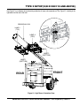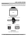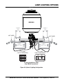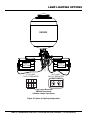
1
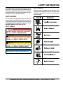
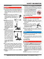
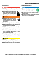
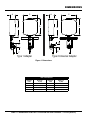
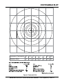
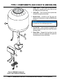
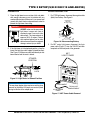
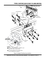
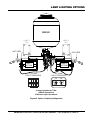
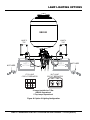
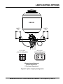
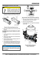
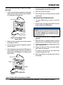
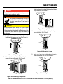
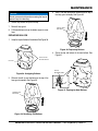
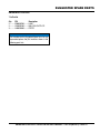
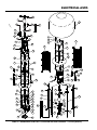
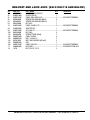
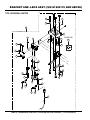
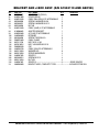
Operation and Parts Manual Globug MODEL GB2000 Light Tower Mount type balloon light Revision #3 (08/30/12) To find the latest revision of this publication, visit our website at: www.multiquip.com THIS MANUAL MUST ACCOMPANY THE EQUIPMENT AT ALL TIMES. proposition 65 warning Diesel engine exhaust and some of page 2 —gb2000 balloon light• operation and parts manual — rev. #3 (08/30/12) Table of Contents GB2000 BALLOON LIGHT Proposition 65 Warning............................................ 2 Table Of Contents..................................................... 3 Parts Ordering Procedures....................................... 4 Safety Information............................................... 5-12 Specifications......................................................... 13 Dimensions............................................................. 14 Footcandle Plot....................................................... 15 General Information................................................ 16 Type 1 Components (S/N G1900118 and Below)... 18 Type 2 Components (S/N G1900119 and Above).. 19 Type 1 Setup (S/N G1900118 and Below)......... 20-22 Type 2 Setup (S/N G1900119 and Above)........ 23-27 Lamp Lighting Options....................................... 28-33 Component Drawings Electrical Assembly........................................... 42-45 Type 1 Bracket and Junction Box Assembly (S/N G1900118 and Below)............................... 46-47 Type 2 Bracket and Junction Box Assembly (S/N G1900119 and Above).............................. 48-49 Terms And Conditions Of Sale — Parts................. 50 Operation........................................................... 34-35 Maintenance...................................................... 36-38 Wiring Diagram....................................................... 39 Explanation Of Code In Remarks Column............. 40 Suggested Spare Parts.......................................... 41 NOTICE Specifications and part numbers are subject to change without notice. gb2000 balloon light• operation and parts manual — rev. #3 (08/30/12)— page 3 www.multiquip.com Parts Ordering Procedures Ordering parts has never been easier! Choose from three easy options: order via internet (dealers only): best deal! Effective: January 1st, 2006 If you have an MQ Account, to obtain a Username and Password, E-mail us at: parts@multiquip. com. Order parts on-line using Multiquip’s SmartEquip website! ■ View Parts Diagrams ■ Order Parts ■ Print Specification Information To obtain an MQ Account, contact your District Sales Manager for more information. Use the internet and qualify for a 5% discount on Standard orders for all orders which include complete part numbers.* Goto www.multiquip.com and click on Order Parts to log in and save! Note: Discounts Are Subject To Change order via Fax (dealers only): All customers are welcome to order parts via Fax. domestic (us) Customers dial: 1-800-6-PARTS-7 (800-672-7877) Fax your order in and qualify for a 2% discount on Standard orders for all orders which include complete part numbers.* Note: Discounts Are Subject To Change order via phone: domestic (us) dealers Call: 1-800-427-1244 non-dealer Customers: Contact your local Multiquip Dealer for parts or call 800-427-1244 for help in locating a dealer near you. International Customers should contact their local Multiquip Representatives for Parts Ordering information. when ordering parts, please supply: ❒ ❒ ❒ ❒ ❒ ❒ dealer account number dealer name and address shipping address (if different than billing address) return Fax number applicable model number Quantity, part number and description of each part ❒ specify preferred method of shipment: ✓ UPS/Fed Ex ✓ DHL ■ Priority One ✓ Truck ■ Ground ■ Next Day ■ Second/Third Day NOTICE All orders are treated as Standard Orders and will ship the same day if received prior to 3PM PST. We aCCepT all maJor CrediT Cards! page 4 —gb2000 balloon light• operation and parts manual — rev. #3 (08/30/12) safety information Do not operate or service the equipment before reading the entire manual. Safety precautions should be followed at all times when operating this equipment. Failure to read and understand the safety messages and operating instructions could result in injury to yourself and others. saFeTy messages saFeTy symbols Potential hazards associated with the operation of this equipment will be referenced with hazard symbols which may appear throughout this manual in conjunction with safety messages. The four safety messages shown below will inform you about potential hazards that could injure you or others. The safety messages specifically address the level of exposure to the operator and are preceded by one of four words: danger, Warning, CauTion or noTiCe. saFeTy symbols danger Indicates a hazardous situation which, if not avoided, Will result in deaTh or serious inJury. Warning Indicates a hazardous situation which, if not avoided, Could result in deaTh or serious inJury. CauTion Indicates a hazardous situation which, if not avoided, Could result in minor or moderaTe inJury. NOTICE Addresses practices not related to personal injury. gb2000 balloon light• operation and parts manual — rev. #3 (08/30/12)— page 5 Safety Information general saFeTy CauTion never operate this equipment without proper protective clothing, shatterproof glasses, respiratory protection, hearing protection, steel-toed boots and other protective devices required by the job or city and state regulations. never operate this equipment when not feeling well due to fatigue, illness or when under medication. never operate this equipment under the influence of drugs or alcohol. alWays check the equipment for loosened threads or bolts before starting. do noT use the equipment for any purpose other than its intended purposes or applications. NOTICE This equipment should only be operated by trained and qualified personnel 18 years of age and older. Whenever necessary, replace nameplate, operation and safety decals when they become difficult read. Manufacturer does not assume responsibility for any accident due to equipment modifications. Unauthorized equipment modification will void all warranties. never use accessories or attachments that are not recommended by Multiquip for this equipment. Damage to the equipment and/or injury to user may result. alWays know the location of the nearest fire extinguisher. alWays know the location of the nearest first aid kit. alWays know the location of the nearest phone or keep a phone on the job site. Also, know the phone numbers of the nearest ambulance, doctor and fire department. This information will be invaluable in the case of an emergency. page 6 —gb2000 balloon light• operation and parts manual — rev. #3 (08/30/12) Safety Information lighT ToWer saFeTy danger never operate the equipment in an explosive atmosphere or near combustible materials. An explosion or fire could result causing severe bodily harm or even death. Warning never disconnect any emergency or safety devices. These devices are intended for operator safety. Disconnection of these devices can cause severe injury, bodily harm or even death. Disconnection of any of these devices will void all warranties. CauTion never lubricate components or attempt service on a running machine. alWays ensure light tower is on level ground before use so that it cannot slide or shift around, endangering workers. Always keep immediate area free of bystanders. alWays make sure trailer is leveled with all outriggers extended before raising tower. Outriggers must remain extended while tower is up. alWays keep area behind trailer clear of people while raising and lowering mast. never remove safety pin or pull mast locking pin while tower is in a raised position! CheCK the mast and winch cables for wear. If any problem occurs when lowering or raising the tower, STOP immediately! Contact a trained technician for assistance. never pivot or retract mast while unit is operating. never use the light tower mast as a crane. do noT lift anything with the mast. alWays lower the light tower when not in use, or if high winds or electrical storms are expected. NOTICE alWays keep the immediate area surrounding the light tower clean, neat, and free of debris. alWays keep the machine in proper running condition. Fix damage to machine and replace any broken parts immediately. alWays store equipment properly when it is not being used. Equipment should be stored in a clean, dry location out of the reach of children and unauthorized personnel. To prevent the light tower from overturning, never use in winds that exceed 65 mph (105 km/h). lamp saFeTy Warning never attempt to replace lamp with the power on. Always shut down the engine and turn off circuit breakers when changing the lamp. alWays allow a sufficient amount of time for the lamp to cool before touching or changing. The possibility exists of severe burns. CauTion never use force when installing the lamp. Excessive force could cause the lamp to break, causing bodily harm. NOTICE never leave any grease or oil residue on lamp surface when replacing or removing lamp. This can create hot spots, reducing the service life of the lamp. alWays make sure lamp surface is clean and dry. alWays replace with MQ recommended type lamp. alWays have a trained technician install and remove a floodlight, or replace any damaged fixture wiring. gb2000 balloon light• operation and parts manual — rev. #3 (08/30/12)— page 7 Safety Information engine saFeTy NOTICE danger The engine fuel exhaust gases contain poisonous carbon monoxide. This gas is colorless and odorless, and can cause death if inhaled. The engine of this equipment requires an adequate free flow of cooling air. never operate this equipment in any enclosed or narrow area where free flow of the air is restricted. If the air flow is restricted it will cause injury to people and property and serious damage to the equipment or engine. DANGEROUS GAS FUMES Warning do noT place hands or fingers inside engine compartment when engine is running. never operate the engine with heat shields or guards removed. Keep fingers, hands hair and clothing away from all moving parts to prevent injury. do noT remove the radiator cap while the engine is hot. High pressure boiling water will gush out of the radiator and severely scald any persons in the general area of the generator. do noT remove the coolant drain plug while the engine is hot. Hot coolant will gush out of the coolant tank and severely scald any persons in the general area of the generator. do noT remove the engine oil drain plug while the engine is hot. Hot oil will gush out of the oil tank and severely scald any persons in the general area of the generator. CauTion never touch the hot exhaust manifold, muffler or cylinder. Allow these parts to cool before servicing equipment. never run engine without an air filter or with a dirty air filter. Severe engine damage may occur. Service air filter frequently to prevent engine malfunction. never tamper with the factory settings of the engine or engine governor. Damage to the engine or equipment can result if operating in speed ranges above the maximum allowable. never tip the engine to extreme angles during lifting as it may cause oil to gravitate into the cylinder head, making the engine start difficult. Wet stacking is a common problem with diesel engines which are operated for extended periods with light or no load applied. When a diesel engine operates without sufficient load (less than 40% of the rated output), it will not operate at its optimum temperature. This will allow unburned fuel to accumulate in the exhaust system, which can foul the fuel injectors, engine valves and exhaust system, including turbochargers, and reduce the operating performance. In order for a diesel engine to operate at peak efficiency, it must be able to provide fuel and air in the proper ratio and at a high enough engine temperature for the engine to completely burn all of the fuel. Wet stacking does not usually cause any permanent damage and can be alleviated if additional load is applied to relieve the condition. It can reduce the system performance and increase maintenance. Applying an increasing load over a period of time until the excess fuel is burned off and the system capacity is reached usually can repair the condition. This can take several hours to burn off the accumulated unburned fuel. State Health Safety Codes and Public Resources Codes specify that in certain locations, spark arresters must be used on internal combustion engines that use hydrocarbon fuels. A spark arrester is a device designed to prevent accidental discharge of sparks or flames from the engine exhaust. Spark arresters are qualified and rated by the United States Forest Service for this purpose. In order to comply with local laws regarding spark arresters, consult the engine distributor or the local Health and Safety Administrator. page 8 —gb2000 balloon light• operation and parts manual — rev. #3 (08/30/12) Safety Information Fuel saFeTy danger do noT start the engine near spilled fuel or combustible fluids. Diesel fuel is extremely flammable and its vapors can cause an explosion if ignited. alWays refuel in a well-ventilated area, away from sparks and open flames. alWays use extreme caution when working with flammable liquids. do noT fill the fuel tank while the engine is running or hot. do noT overfill tank, since spilled fuel could ignite if it comes into contact with hot engine parts or sparks from the ignition system. Store fuel in appropriate containers, in well-ventilated areas and away from sparks and flames. never use fuel as a cleaning agent. do noT smoke around or near the equipment. Fire or explosion could result from fuel vapors or if fuel is spilled on a hot engine. ToWing saFeTy — lighT ToWer CauTion Check with your local county or state safety towing regulations, in addition to meeting Department of Transportation (DOT) Safety Towing Regulations, before towing your light tower. In order to reduce the possibility of an accident while transporting the light tower on public roads, alWays make sure the trailer that supports the light tower and the towing vehicle are mechanically sound and in good operating condition. alWays inspect the hitch and coupling for wear. never tow a trailer with defective hitches, couplings, chains, etc. Check the tire air pressure on both towing vehicle and trailer. Trailer tires should be inflated to 50 psi cold. Also check the tire tread wear on both vehicles. alWays make sure the trailer is equipped with a safety chain. alWays properly attach trailer’s safety chains to towing vehicle. alWays make sure the vehicle and trailer directional, backup, brake and trailer lights are connected and working properly. DOT Requirements include the following: • Connect and test electric brake operation. • Secure portable power cables in cable tray with tie wraps. The maximum speed for highway towing is 55 mph (86 km/h) unless posted otherwise. Recommended offroad towing is not to exceed 15 mph (24 km/h)or less depending on type of terrain. Avoid sudden stops and starts. This can cause skidding, or jack-knifing. Smooth, gradual starts and stops will improve towing. Avoid sharp turns to prevent rolling. Trailer should be adjusted to a level position at all times when towing. Raise and lock trailer jack stands in up position when towing. NOTICE alWays remove and stow the GB2000 lamp fixture prior to towing the light tower. alWays shutdown engine before transporting. Make sure the hitch and coupling of the towing vehicle are rated equal to, or greater than the trailer “gross vehicle weight rating.” gb2000 balloon light• operation and parts manual — rev. #3 (08/30/12)— page 9 Safety Information TransporTing saFeTy If lifting through pockets, make sure forks of forklift are inserted in pockets as far as possible before lifting. CauTion Before lifting, make sure that light tower parts are not damaged and screws are not loosened or lost. Place chock blocks underneath wheel to prevent rolling while parked. alWays make sure crane or lifting device has been properly secured to lifting hook of the equipment. Place support blocks underneath the trailer’s bumper to prevent tipping while parked. never lift the equipment while engine is running. Use the trailer’s swivel jack to adjust the trailer height to a level position while parked. Remove fan power cord from junction box before towing. Make sure tower (mast) is in the stowed position and the GB2000 is removed from the mast before lifting. REMOVE GB2000 BEFORE TRANSPORTING STOWED POSITION MAST LOCK never allow any person or animal to stand underneath the equipment while lifting. do noT lift equipment to unnecessary heights. loading and Tie-down on Flatbed Truck NOTICE Before loading light tower to flatbed truck, disconnect all connectors and tie-wrap the cables against the T-bar to prevent damage to the cables and connectors. REMOVE FAN POWER CORD alWays Make sure rear mast lock is secure before lifting. Use adequate lifting cable (wire or rope) of sufficient strength. Use one point suspension hook and lift straight upwards. Remove and stow the GB2000 in a safe place where it will not get damaged before loading the light tower onto a flatbed truck, towing, or shipping via a container. When loading onto flatbed truck, make sure that front jackstand of light tower is retracted and in the horizontal position so that the foot does not make contact with the deck floor. FRONT JACKSTAND RETRACTED TRANSPORT TIE-DOWN POINT (4) TONGUE SIDE JACK STAND (2) LIFTING BALE LIGHT TOWER FORKLIFT POCKETS REAR JACK STAND (2) Make sure that the two side (left and right) and two rear jackstands are in the vertical postion, slightly extended, so that each foot makes contact with the deck floor. Straps and chains should be routed through the transport tie-down points located beneath each corner of the cabinet to allow even application of force to the front and rear of the machine. do noT secure the unit by running a strap or chain over the tongue of the light tower. This may cause severe damage to the unit. page 10 —gb2000 balloon light• operation and parts manual — rev. #3 (08/30/12) Safety Information eleCTriCal saFeTy danger The electrical voltage required to operate the generator can cause severe injury or even death through physical contact with live circuits. Turn generator and all circuit breakers oFF before performing maintenance on the generator. never insert any objects into the output receptacles during operation. This is extremely dangerous. The possibility exists of electrical shock, electrocution or death. never operate light tower or handle any electrical equipment while standing in water, while barefoot, while hands are wet or in the rain. A dangerous electrical shock could occur, causing severe bodily harm or even death. alWays make sure the area above the light tower is open and clear of overhead power lines and other obstructions. The tower extends in excess of 30 feet (9 meters). Contact w i t h ove r h e a d p owe r lines or other obstructions could result in equipment damage, electrical shock, electrocution and even death. Similar to boom equipment, light tower may become energized with high voltage. do noT operate the light tower within a radial distance of 17 feet (5.1 meters) from high voltage power lines. If light tower becomes energized with high voltage, contact with the equipment could result in electrocution. never operate GB2000 in winds in excess of 40 mph (64 km/h). Backfeed to a utility system can cause electrocution and/or property damage. never connect the generator to a building’s electrical system without a transfer switch or other approved device. All installations should be performed by a licensed electrician in accordance with all applicable laws and electrical codes. Failure to do so could result in electrical shock or burn, causing serious injury or even death. power Cord/Cable safety danger never let power cords or cables lay in water. never use damaged or worn cables or cords when connecting equipment to generator. Inspect for cuts in the insulation. never grab or touch a live power cord or cable with wet hands. The possibility exists of electrical shock, electrocution or death. Make sure power cables are securely connected. Incorrect connections may cause electrical shock and damage to the light tower. NOTICE alWays make certain that proper power or extension cord has been selected for the job. Ensure fan power cable is safely routed and secured as it travels from the junction box down the mast to the GFCI receptacle. grounding safety danger The light tower is equipped with a ground terminal for your protection. alWays complete the grounding path from the light tower to an extrnal grounding source. alWays make sure that electrical circuits are properly grounded to a suitable earth ground (ground rod) per the National Electrical Code (NEC) and local codes before operating generator. severe injury or death by electrocution can result from operating an ungrounded generator. never use gas piping as an electrical ground. gb2000 balloon light• operation and parts manual — rev. #3 (08/30/12)— page 11 Safety Information baTTery saFeTy danger do noT drop the battery. There is a possibility that the battery will explode. do noT expose the battery to open flames, sparks, cigarettes, etc. The battery contains combustible gases and liquids. If these gases and liquids come into contact with a flame or spark, an explosion could occur. Warning environmenTal saFeTy NOTICE Dispose of hazardous waste properly. Examples of potentially hazardous waste are used motor oil, fuel and fuel filters. do noT use food or plastic containers to dispose of hazardous waste. do noT pour waste, oil or fuel directly onto the ground, down a drain or into any water source. alWays wear safety glasses when handling the battery to avoid eye irritation. The battery contains acids that can cause injury to the eyes and skin. Use well-insulated gloves when picking up the battery. alWays keep the battery charged. If the battery is not charged, combustible gas will build up. alWays recharge the battery in a well-ventilated environment to avoid the risk of a dangerous concentration of combustible gasses. If the battery liquid (dilute sulfuric acid) comes into contact with clothing or skin, rinse skin or clothing immediately with plenty of water. If the battery liquid (dilute sulfuric acid) comes into contact with eyes, rinse eyes immediately with plenty of water and contact the nearest doctor or hospital to seek medical attention. CauTion alWays disconnect the negaTive battery terminal before performing service on the generator. alWays keep battery cables in good working condition. Repair or replace all worn cables. page 12 —gb2000 balloon light• operation and parts manual — rev. #3 (08/30/12) Specifications Table 1. Specifications Model GB2000 Type 1000 W Metal Halide (X2) Number of Bulbs 2 Lamp Current 8.2 A Voltage 238 268 V Lumens 220,000 lm Current 0.87 A Fan Voltage 115 V 12.2 x 12.2 x 39 in Storage (310 x 310 x 990 mm) Dimensions 36 x 36 x 39 in Working (900 x 900 x 990 mm) Total Weight 31 lb (14 kg) Appropriate Generator 3.2 kW and above gb2000 balloon light• operation and parts manual — rev. #3 (08/30/12)— page 13 dimensions C A C A D B D B E G H F Type 1 Adapter Type 2 Universal Adapter Figure 1. Dimensions Table 2. Dimensions Reference Letter Dimension in. (mm) Reference Letter Dimension in. (mm) A 13.25 (337) E 3.12 (79.3) B 40.0 (1,016) F 9.75 (248) C 35.5 (902) G 8.25 (210) D 34.5 (876) H 4.62 (117) page 14 —gb2000 balloon light• operation and parts manual — rev. #3 (08/30/12) footcandle plot 30 20 10 5 2 1 0.5 0.25 1 grid = 40 ft. Illuminance (Footcandle) 30 20 10 5 2 Diameter (Feet) 9 30 52 65 91 1 0.5 0.25 117 156 232 Figure 2. Footcandle Plot gb2000 balloon light• operation and parts manual — rev. #3 (08/30/12)— page 15 GENERAL INFORMATION The GB2000 lamp fixture is a difused balloon light that is designed to be mounted and operated on most convential mobile light tower masts. Its design and features permit clean, difused light to be cast uniformly over 232 feet (70.7 meters). The shadow-less lighting dramatically reduces glare in the work area. This type of lighting improves safety and enhances the illuminated area. the GB2000 is ideal for highway work, construction job sites, security support, and special events. The balloon light assembly is supported by two 1000 watt metal halide lamps, self-inflating durable polyester balloon bag, protective lamp guard, quick disconnect communal mast bracket, and self-contained electrical junction box. Once attached to the mast, the GB2000 utilizes the ballast assembly, electrical conduits, and receptacle connections of conventional mobile light towers to permit operation. The GB2000 requires 2000 watts of power and the host light tower electrical ballast system for operation. Total lamp operation will be limited to the design and capacity of the host light tower. The unit easily disconnects from the light tower mast and can be easily stored in its protective canvas cover case. page 16 —gb2000 balloon light• operation and parts manual — rev. #3 (08/30/12) notes gb2000 balloon light• operation and parts manual — rev. #3 (08/30/12)— page 17 type 1 COMPONENTS (S/N g1900118 and below) 1. Lamp Fixture — Made of heat resistant polyester balloon, with a diameter of 35.5 inches (902 mm) and two 1000 watt metal halide lamps. 2. Locking Pin — Locks the lamp fixture in place when attached to the pole on the bracket. 3. Bracket Plate — Attaches to the Tbar and mast interface of the light tower to allow the GB2000 to be installed. NOTICE 1 This bracket only fits on Multiquip light towers. 4. Junction Box — Holds the electrical connection and cables to connect the lamp fixture to the TBar and to the power cable. 2 5. Power Cable — Connects the lamp fixture from the junction box to the GFCI receptacle of the generator to provide power to inflate the balloon. 3 4 5 Figure 3. GB2000 Components (Type 1 S/N G1900118 And Below) page 18 —gb2000 balloon light• operation and parts manual — rev. #3 (08/30/12) type 2 COMPONENTS (S/N g1900119 and above) 1. Lamp Fixture — Made of heat resistant polyester balloon, with a diameter of 35.5 inches (902 mm) and two 1000 watt metal halide lamps. 1 2. Locking Pin — Locks the lamp fixture in place when attached to the pole on the bracket. 3. Balloon Power Cable — Provides AC power to the lamps, fan and baloon inflation circuit. 4. Adapter Plate — Attaches to the T-Bar and mast interface of the light tower to allow the GB2000 to be installed. NOTICE Type 2 adapter plate fits most conventional light tower masts. 5. Junction Box — Holds the electrical connection and cables to connect the lamp fixture to the T-Bar and to the power cable. 6. Support Bracket — Attaches to T-Bar to support adapter plate (hardware not shown). 2 3 5 7. Connector Caps — Provides protection to the receptacles on the junction box when not in use. 8. Fan Power Cable — 38 ft. (11.5 meters) cable that provides 120 VAC from a GFCI receptacle (generator) to the T-Bar mounted junction box to run the balloon fan and inflate the balloon. 4 6 7 8 Figure 4. GB2000 Components (Type 2 S/N G190019 And Above) gb2000 balloon light• operation and parts manual — rev. #3 (08/30/12)— page 19 type 1 setup (S/N G1900118 and below) PReparation 1. Place the light tower in an area free of dirt and debris with enough clearance as not to interfere with any overhead obstructions. Make sure it is on secure level ground with chock blocks underneath each wheel to prevent the light tower from rolling. 2. For MLT series light towers disconnect the 4-pin power cable (Figure 7) from the 125 VAC twist-lock receptacle on the front panel of the generator. MLT LIGHT TOWER DANGER ALWAYS make sure the area above light tower is open and clear of overhead power lines and other obstructions. The tower extends in excess of 30 ft. (9 meters). Contact with overhead power lines or other obstructions could result in equipment damage, serious injury or death! 2. If the light tower is in the deployed position, place the tower mast into the cradle support (stowed position). See Figure 5. Make sure cradle lock/release pin has been inserted and the mast is locked. WHISPERWA TT 7KW AC Model DA-7000S S ON AC CIRCUIT BREAKER OFF IDLE CONTROL AC VOLTMETE R STOP RUN HEAT START 00000 7000 WATT DIESEL POW HOURS ERED AC GEN STARTER SWITC HOUR METER ERATOR H 20A 25A 120V 25A 25A 120/240V DISCONNECT TO BALLAST COMPARTMENT 4-PIN POWER CABLE Figure 7. MLT Power Cable Removal 3. Disconnect the lamp power cables from receptacles J1 thru J4 on the T-Bar assembly. See Figure 8. STOWED POSITION MAST LOCK UNPLUG THE CABLES FROM THE RECEPTACLES Figure 5. Light Tower in Stowed Position Disassembly J4 J3 J2 J1 1. For LT12D light towers, disconnect the negative cable (black) from battery. See Figure 6. DISCONNECT NEGATIVE BATTERY CABLE Figure 8. Remove Cables 4. Remove all 4 lamps (Figure 9) from the T-Bar by removing the bolts (with washers and nuts) securing each lamp to the T-Bar. 5. Keep the removed lamps and the associated hardware together and store in a safe place, making sure that the lamps are properly protected to prevent breakage. Figure 6. Disconnecting Battery page 20 —gb2000 balloon light• operation and parts manual — rev. #3 (08/30/12) type 1 setup (S/N G1900118 and below) LAMP BOLT WASHERS MAST T-BAR BRACKET WASHERS NUT INSTALL SCREWS AND NUTS (2) Figure 11. Installing Bracket Figure 9. Lamp Removal assembly 3. Attach junction box (Figure 12) to lamp mounting bracket with the bolts and washers provided. CAUTION Make sure that the T-bar is supported before removing the two screws and nuts to prevent T-Bar from falling off the mast extension. 1. Remove the 2 screws and 2 nuts that secure the T-Bar to the mast extension. Discard these items they will not be used in the reassembly. See Figure 10. MAST T-BAR NOT SHOWN INSTALL SCREWS AND LOCKWASHERS (2) BRACKET REMOVE NYLOC NUT (2) 1/2-13 P/N 10176 JUNCTION BOX MAST REMOVE HHC SCREW (2) 1/ 2 -13X3-1/4 P/N 06503-026 CONNECTORS T-BAR Figure 12. Junction Box Installation Figure 10. Removing Screws and Nuts 2. Install the lamp mounting bracket (Figure 11) onto the T-Bar and mast extension with the new screws and nuts provided. gb2000 balloon light• operation and parts manual — rev. #3 (08/30/12)— page 21 type 1 setup (S/N G1900118 and below) 4. Place the GB2000 lamp fixture (Figure 13) onto the lamp mounting bracket. Lock the lamp fixture in place with the cotter pin. LOCKING PIN LB2000 LAMP FIXTURE Fan/Balloon Power cable Connection 1. Insert the 38 ft. (11.5 meters), 3-prong AC power plug on the fan power cable as shown in Figure 14 into the GFCI power receptacle on the generator. 2. Connect the other end of the fan power cable (quick disconnect end) to the 3-pin AC power cable on the junction box. 10-PIN Lamp Power cable CONNECTION 1. Unscrew the protective cap from the lamp power receptacle on the junction box. POLE ON BRACKET 2. Connect the 10-pin lamp power cable from the balloon to the 10-pin lamp power receptacle on the junction box as shown in Figure 14. COTTER PIN Figure 13. Installing GB2000 Lamp Fixture Lamp cable connections lt12 5. Unscrew the protective cap from the lamp power receptacle on the junction box. 1. For LT12 series light towers connect the 2 lamp power cables (Figure 14) from the junction box to the J3 and J4 receptacles on the T-Bar as shown in Figure 14. 6. Connect the lamp power cord from the GB2000 lamp fixture to lamp power receptace on the junction box as shown in Figure 14. 2. If necessary, reinstall bottom lamps onto the T-Bar. At the T-Bar, connect bottom lamps as shown in the lighting option section of this manual. Lamp cable Connections MLT J4 J1 J2 J3 FAN POWER CABLE T-BAR 1. For MLT series light towers connect the 2 lamp power cables from the junction box to the J3 and J4 receptacles on the T-Bar as shown in Figure 14. 2. If necessary, reinstall bottom lamps onto the T-Bar. At the T-Bar, connect bottom lamps as shown in the lighting option section of this manual. GFCI 3-PIN AC POWER CABLE CAP JUNCTION BOX 10-PIN LAMP POWER CABLE 3-PIN LAMP POWER CABLES Figure 14. Junction Box Connections page 22 —gb2000 balloon light• operation and parts manual — rev. #3 (08/30/12) type 2 setup (S/N G1900119 and above) PReparation Power Disconnection 1. Place the light tower in an area free of dirt and debris with enough clearance as not to interfere with any overhead obstructions. Make sure it is on secure level ground with chock blocks underneath each wheel to prevent the light tower from rolling. 1. For LT12D light towers, disconnect the negative cable (black) from battery. See Figure 6. DISCONNECT NEGATIVE BATTERY CABLE DANGER ALWAYS make sure the area above light tower is open and clear of overhead power lines and other obstructions. The tower extends in excess of 30 ft. (9 meters). Contact with overhead power lines or other obstructions could result in equipment damage, serious injury or death! 2. If the light tower is in the deployed position, place the tower mast into the cradle support (stowed position). See Figure 15. Make sure cradle lock/release pin has been inserted and the mast is locked. Figure 16. Disconnecting Battery 2. For MLT series light towers disconnect the 4-pin power cable (Figure 17) from the 120 VAC twist-lock receptacle on the front panel of the generator. MLT LIGHT TOWER STOWED POSITION WHISPERWA TT 7KW AC MAST LOCK Model DA-7000S S ON AC CIRCUIT BREAKER OFF IDLE CONTROL AC VOLTMET RUN HEAT START 00000 HOURS ERED AC GEN ERATOR Figure 15. Light Tower in Stowed Position STOP ER 7000 WATT DIESEL POW STARTER SWIT CH HOUR METER 20A 25A 120V 25A 25A 120/240V NOTICE The new lamp adapter plate requires no existing lamp removal for installation. All lamps can remain in place during installation of the adapter plate. DISCONNECT 4-PIN POWER CABLE TO BALLAST COMPARTMENT Figure 17. MLT Power Cable Removal gb2000 balloon light• operation and parts manual — rev. #3 (08/30/12)— page 23 type 2 setup (S/N G1900119 and above) Lamp adapter Plate mounting Installation 1. Remove the adapter plate kit hardware from its container. 2. Before proceeding make sure the light tower mast is in the stow position (down) and the cradle lock/release pin has been inserted and the mast is locked. 3. Attach the lamp adapter plate to the T-Bar as shown in Figure 18. Align adapter plate so that adapter spacer notch fits over screw on T-Bar. Please pay close attention to the orientation of the 2 support brackets. 4. Mount the flat end of both support brackets flush against the T-Bar with the low end of each bracket facing inward toward the mast. The raised end of each bracket should be facing outward. NOTICE Please pay close attention to the orientation of the 2 support brackets. Each bracket has a high and low side. the low side of the bracket should be facing inwards towards the mast. 5. Next, insert a bolt (4) and flat washer (4) thru the mounting holes on the the adapter plate as shown in Figure 18. Again, pay close attention on which set of holes to insert the bolt thru. Bolt number 2 must be oriented so that it passes between receptacles J1 and J2 on the T-Bar. 6. Secure the adapter plate to the T-Bar using the supplied flat washer (4), lock washer (4) and nut (4). Make sure the adapter plate is level (use a bubble level) and both brackets are straight (vertical), not slanted before tightening page 24 —gb2000 balloon light• operation and parts manual — rev. #3 (08/30/12) type 2 setup (S/N G1900119 and above) VIEW FROM BACK SIDE BUBBLE LEVEL 2 1 LOCK WASHER (4) HEX NUT (4) 3 SPACER 1 LOW END 2 4 FLUSH W/ T-BAR BOTTOM FLAT WASHER (8) SUPPORT BRACKET (2) BOLT T-BAR BOLT (4) LAMP ADAPTER PLATE T-BAR 1 BACK SIDE UNDERNEATH 3 BOLT 2 2 LAMP ADAPTER PLATE 4 SUPPORT BRACKET J1 NOTES: J2 1 It is important for the adapter SPACER to seat against the T-Bar as shown above. 2 For proper alignment of the adapter plate, use of a bubble level is required. Figure 18. Adapter Plate Mounting Installation gb2000 balloon light• operation and parts manual — rev. #3 (08/30/12)— page 25 type 2 setup (S/N G1900119 and above) junction box mounting Lamp mounting 1. Secure the junction box (Figure 19) to the adapter plate using the supplied bolts (2), lock washer (2), and flat washer (2). Tighten mounting bolts securely. 1. Place the GB2000 lamp fixture onto the lamp adapter plate pole as shown in Figure 20. LAMP ADAPTER PLATE T-BAR 2. Insert locking pin into hole opening on pole, then insert cotter pin to lock pin in place. fan power cable connection 1. Insert the 38 ft. (11.5 meters), 3-prong AC power plug on the fan power cable as shown in Figure 20 into the GFCI power receptacle on the generator. BOLT (2) 2. Connect the other end of the fan power cable (quick disconnect end) to the 3-pin AC power receptacle on the junction box. POLE LOCK WASHER (2) NOTICE Once the tower is raised and in position, the fan power cable should be secured in such a way as to prevent tripping and entanglement. FLAT WASHER (2) JUNCTION BOX Balloon Power cable 1. Connect the balloon power cable (Figure 20) to the 10-pin receptacle on the junction box. Figure 19. Junction Box Mounting LAMP 2 (TOP) LAMP 1 (BOTTOM) FAN POWER CABLE GFCI LOCKING PIN LAMP 3 (BOTTOM) J4 J3 J2 J1 PLATE ADAPTER POLE COTTER PIN LAMP 4 (TOP) JUNCTION BOX 2 FT. (10 PIN) BALLOON POWER CABLE BALLOON FIXTURE Figure 20. Fan/Balloon Power Cable Connections page 26 —gb2000 balloon light• operation and parts manual — rev. #3 (08/30/12) type 2 setup (S/N G1900119 and above) Use Figure 21 as a reference when determining orientation of lamps and receptacles on T-Bar. Figure 21 is looking at the light tower from the rear to the front. J4 GB2000 BALLOON LAMP 2 LAMP 2 (TOP) LAMP 4 J2 LAMP 4 (TOP) J3 LAMP 1 LAMP 3 J1 LAMP 3 (BOTTOM) LAMP 1 (BOTTOM) REAR FRONT Figure 21. Light Tower Orientation View gb2000 balloon light• operation and parts manual — rev. #3 (08/30/12)— page 27 lamp lighting options Lamp Cable connections On the T-Bar (Figure 22) there are four power receptacles J1, J2, J3 and J4. These receptacles provide AC power to the existing rectangular lamps. When the GB2000 lamp assembly is employed only two of the existing rectangular lamps (bottom lamps recommended) will be available for use. Please reference Figure 22 thru Figure 27 for the various lighting options. GB2000 JUNCTION BOX T-BAR 1 2 3 4 LT12 LAMP CIRCUIT BREAKERS MLT LAMP CIRCUIT BREAKERS CB1 OFF OFF ON ON ON CB2 OFF CB1 CB2 CB3 CB4 All Lamps Removed GB2000 Operational Figure 22. Option 1 Lighting Configuration page 28 —gb2000 balloon light• operation and parts manual — rev. #3 (08/30/12) lamp lighting options Table 3. GB2000 LAMP 2 TOP LAMP 4 TOP NOT USED NOT USED 1 2 3 4 LAMP 3 BOTTOM LAMP 1 BOTTOM LT12 LAMP CIRCUIT BREAKERS OFF OFF ON ON MLT LAMP CIRCUIT BREAKERS CB1 CB2 ON OFF CB1 CB2 CB3 CB4 4 Lamps Installed on T-Bar Only GB2000 Operational Figure 23. Option 2 Lighting Configuration gb2000 balloon light• operation and parts manual — rev. #3 (08/30/12)— page 29 lamp lighting options GB2000 1 2 3 4 LAMP 3 BOTTOM LAMP 1 BOTTOM LT12 LAMP CIRCUIT BREAKERS ON ON ON ON MLT LAMP CIRCUIT BREAKERS CB1 CB2 ON ON CB1 CB2 CB3 CB4 2 Top Lamps Removed GB2000 Operational 2 Bottom Lamps Operational Figure 24. Option 3 Lighting Configuration page 30 —gb2000 balloon light• operation and parts manual — rev. #3 (08/30/12) lamp lighting options GB2000 LAMP 2 TOP LAMP 4 TOP NOT USED NOT USED 1 2 3 4 LAMP 3 BOTTOM LAMP 1 BOTTOM LT12 LAMP CIRCUIT BREAKERS ON ON ON ON MLT LAMP CIRCUIT BREAKERS CB1 CB2 ON ON CB1 CB2 CB3 CB4 4 Lamps Installed on T-Bar GB2000 Operational 2 Bottom Lamps Operational Figure 25. Option 4 Lighting Configuration gb2000 balloon light• operation and parts manual — rev. #3 (08/30/12)— page 31 lamp lighting options GB2000 LAMP 2 TOP LAMP 4 TOP 1 2 3 4 NOT USED LAMP 3 BOTTOM LAMP 1 BOTTOM LT12 LAMP CIRCUIT BREAKERS ON ON ON ON NOT USED MLT LAMP CIRCUIT BREAKERS CB1 CB2 ON ON CB1 CB2 CB3 CB4 4 Lamps Installed on T-Bar GB2000 Operational 2 Top Lamps Operational Figure 26. Option 5 Lighting Configuration page 32 —gb2000 balloon light• operation and parts manual — rev. #3 (08/30/12) lamp lighting options GB2000 LAMP 2 TOP LAMP 4 TOP 1 2 3 4 LT12 LAMP CIRCUIT BREAKERS ON ON ON ON MLT LAMP CIRCUIT BREAKERS CB1 CB2 ON ON CB1 CB2 CB3 CB4 2 Bottom Lamps Removed GB2000 Operational 2 Top Lamps Operational Figure 27. Option 6 Lighting Configuration gb2000 balloon light• operation and parts manual — rev. #3 (08/30/12)— page 33 operation Removing balloOn protective cover LT12 LIGHT TOWER CAUTION DO NOT use excessive force when zipping or unzipping the balloon. The possibility exists of the zipper tearing, which would make the balloon unusable. 240 VAC/30A MAIN BREAKER MAIN CIRCUIT BREAKER ON GFCI CIRCUIT BREAKER ON CB1 CB2 CB3 CB4 1. Expose the balloon by unsnapping the buttons and unzipping the protective cover as shown in Figure 28. UNZIP PROTECTIVE COVER SNAPS BALLOON FULLY EXPOSED 120 VAC/15A GFCI BREAKER LIGHT CONTROL/BREAKER Figure 29. Main, GFCI Circuit Breakers (ON/LT12) 5. Next, turn on lamp circuit breakers as referenced in the lamp lighting options section of this manual. 6. Secure any unused lamp cables. 7. Raise the light tower mast (Figure 30) to the desired upright height. FOLD PROTECTIVE COVER INTO ITSELF Figure 28. Removing Protective Cover 2. Next, fold the protective cover into itself and zip. See Figure 28. INFLATING BALLOON AND TURNING ON LAMPs LT12 only LAMP 2 LAMP 2 FACING OUTWARD BALLOON LAMP 4 1. On LT12 series light towers, reconnect negative battery cable (black). 2. Slightly raise the light tower mast to allow clearance for the balloon to inflate. LAMP 4 FACING OUTWARD 3. Start the light tower engine as referenced in the LT12 light tower operation manual. 4. Once, the engine has started, place the GFCI and main circuit breaker switches (Figure 29) on the LT12 control panel in the ON position. The balloon should begin to inflate. NOTICE LAMP 1 NOT USED NOT USED LAMP 3 Figure 30. Balloon Deployed (Typical Application) Ensure the fan power cable is routed safely as it travels from the junction box, down the mast to the selected GFCI receptacle. page 34 —gb2000 balloon light• operation and parts manual — rev. #3 (08/30/12) operation INFLATING BALLOON AND TURNING ON LAMPs mlt only 5. Next, turn on lamp circuit breakers as referenced in the lamp lighting options section of this manual. 1. On MLT series light towers, reconnect the 4-pin power cable (Figure 31) to the 120 VAC twist-lock receptacle on the front panel of the generator. 6. Secure any unused lamp cables. 7. Raise the light tower mast (Figure 30) to the desired upright height. deflating and storing balloon MLT LIGHT TOWER 1. Turn lamps OFF and allow to cool for at least five minutes. WHISPERWA TT 7KW AC 2. Once the lamps have cooled, place the GFCI and main breaker switches in the OFF position. Model DA-7000SS ON OFF IDLE CONTROL AC VOLTMETE AC CIRCU IT BREAKER RUN STOP HEAT R START 00000 7000 WATT DIESEL POW HOURS ERED AC GENE STARTER SWITC HOUR METER RATOR H NOTICE 20A 25A 25A 120V 25A 120/240V TO BALLAST COMPARTMENT 4-PIN POWER CABLE Figure 31. MLT Ballast 4-pin Power Cable 2. Slightly raise the light tower mast to allow clearance for the balloon to inflate. 3. Start the light tower engine as referenced in the MLT operation manual. 4. Once, the engine has started, place the GFCI and main circuit breaker switches (Figure 32) on the MLT front control panel in the ON position. The balloon should begin to inflate. ALWAYS make sure lamps are turned off and allowed to cool before deflating balloon to avoid any damage to the balloon. NEVER transport GB2000 lamp fixture while attached to mast. 3. Unplug power cord from the GFCI receptacle on the generator. 4. When the balloon is completely deflated, unzip the protective cover and fold the balloon inside the cover. 5. Carefully zip up the cover and snap the buttons to fully close the protective cover. 6. Remove all cables from T-Bar, and remove balloon power cable from junction box. 7. Pull cotter pin from locking pin and remove lamp assembly from light tower mast. 8. Store lamp assembly in a safe place where it will not get damaged. MLT LIGHT TOWER MAIN CIRCUIT BREAKER (ON) WHISPERWA TT 7KW AC Model DA-7000SS ON AC CIRCU IT BREAKER OFF IDLE CONTROL AC VOLTMETE STOP HEAT START 00000 7000 WATT DIESEL POW HOURS ERED AC GENE STARTER SWITC HOUR METER RATOR H GFCI CIRCUIT BREAKER (ON) 20A 25A 120V RUN R 25A 25A 120/240V 4-PIN POWER CABLE TO BALLAST COMPARTMENT Figure 32. Main, GFCI Circuit Breakers (ON/MLT) gb2000 balloon light• operation and parts manual — rev. #3 (08/30/12)— page 35 maintenance REPLACING LAMP 3. Press the tabs on the lamp holder and push up lamp holder to release it from lamp. Do the same to the lower lamp if necessary. See Figure 35. DANGER Never attempt to replace lamp in a wet place. The possibility exists of electric shock. WARNING LAMP HOLDER Always allow sufficient time for the lamp to cool down before replacing. The possibility exists of severe burns if hot lamp is touched. \ LAMP HOLDER STOPPER CAUTION Always shutdown power source and remove balloon assembly from mast when replacing a broken lamp. Utmost care should be taken in handling broken lamp. The possibility exists of serious injury from handling a broken lamp. Figure 35. Lamp Holder 4. Remove lamp from the lamp socket by turning lamp counterclockwise. See Figure 36. 1. Unzip the zipper at the bottom of the balloon and roll the balloon up to expose the lamp. See Figure 33. LAMP BALLOON LAMP SOCKET ZIPPER Figure 36. Removing Lamp Figure 33. Exposing Balloon 5. Install new lamp into socket and turn lamp in a clockwise direction until tight. See Figure 37. 2. Release the lamp guard hooks from the poles and remove the two lamp guards. See Figure 34. LAMP LAMP SOCKET LAMP GUARD Figure 37. Installing New Lamp LOCK HOOK Figure 34. Removing Lamp Guard page 36 —gb2000 balloon light• operation and parts manual — rev. #3 (08/30/12) maintenance NOTICE Do not use excessive force when screwing the lamp to prevent lamp from breaking. 3. Slide in the new replacement balloon over the top of the lamp guard assembly. See Figure 40. 6. Secure lamp holder on top of the lamp. 7. Reinstall lamp guard. 8. Pull down balloon and zip the bottom zipper to cover lamp. INSTALL NEW BALLOON REPLACING BALLOON 1. Unzip the top and bottom of the balloon. See Figure 38. Figure 40. Replacing Balloon 4. Zip up the top and bottom of the new balloon. See Figure 41. UNZIP TOP AND BOTTOM ZIPPERS BALLOON Figure 38. Unzipping Balloon ZIP UP NEW BALLOON 2. Slide out the old or worn balloon over the top of the lamp guard assembly. See Figure 39. Figure 41. Zipping Up New Balloon REMOVE OLD BALLOON Figure 39. Removing Old Balloon gb2000 balloon light• operation and parts manual — rev. #3 (08/30/12)— page 37 maintenance SYMPTOM Lamp does not light. Lamp only lights for a short time. Balloon does not inflate. Table 4. Troubleshooting POSSIBLE PROBLEM Is plug disconnected? Is generator power switched off? Is lamp loose? Is power connector disconnected or loose? Is model of lamp incompatible? Is ambient temperature too high more than 104° F (40° C)? Is fan motor not working properly? Is balloon cloth defective? SOLUTION Plug in correctly. Turn on switch. Screw lamp securely into socket. Connect disconnected connector. Use genuine MQ lamp. Move lamp where there is proper ventilation. Check and repair fan motor. Repair or replace balloon cloth. page 38 —gb2000 balloon light• operation and parts manual — rev. #3 (08/30/12) wiring diagram RED F M WHITE SOCKET WHITE THERMO F UPPER LAMP M CABLE (THERMO) 2 CP F WHITE BLACK 2 x 1000 WATT METAL HALIDE LAMP CABLE (THERMO) 1 CP M M F CABLE (LAMP) 2 CP WHITE CABLE (THERMO) 4 CP F THERMO SOCKET LOWER LAMP M F BLACK CABLE (THERMO) 3 CP M M WHITE CABLE NO. RED FLANGE 1 2 M M M F F F F GREEN FAN MOTOR BLACK BLACK BLACK BLACK BLACK F M F M BLACK CABLE NO. BLACK BLUE 5 6 4 10 3 2 1 CABLE (BALLOON) 1 CP BALLOON ASSY CABLE (BALLOON) 2 CP JUNCTION BOX 5 6 4 10 3 2 1 WHITE WHITE BLACK BLUE RED M M WHITE M M M F F M GREEN F F F WHITE F BLACK BLACK WHITE BLACK WHITE CABLE (FAN) CP GREEN GREEN GREEN AC PLUG CP BOX (RELAY) AC120V CABLE (BALLOON) 3 CP gb2000 balloon light• operation and parts manual — rev. #3 (08/30/12)— page 39 Explanation of Code in Remarks Column The following section explains the different symbols and remarks used in the Parts section of this manual. Use the help numbers found on the back page of the manual if there are any questions. NOTICE The contents and part numbers listed in the parts section are subject to change without notice. Multiquip does not guarantee the availability of the parts listed. sample parTs lisT no. 1 2% 2% 3 4 parT no. parT name QTy. remarKs 12345 BOLT .....................1 .....INCLUDES ITEMS W/% WASHER, 1/4 IN. ..........NOT SOLD SEPARATELY 12347 WASHER, 3/8 IN. ..1 .....MQ-45T ONLY 12348 HOSE ..................A/R ...MAKE LOCALLY 12349 BEARING ..............1 .....S/N 2345B AND ABOVE no. Column QTy. Column numbers used — Item quantity can be indicated by a number, a blank entry, or A/R. A/R (As Required) is generally used for hoses or other parts that are sold in bulk and cut to length. A blank entry generally indicates that the item is not sold separately. Other entries will be clarified in the “Remarks” Column. remarKs Column Some of the most common notes found in the “Remarks” Column are listed below. Other additional notes needed to describe the item can also be shown. assembly/Kit — All items on the parts list with the same unique symbol will be included when this item is purchased. unique symbols — All items with same unique symbol Indicated by: “INCLUDES ITEMS W/(unique symbol)” (@, #, +, %, or >) in the number column belong to the same assembly or kit, which is indicated by a note in the “Remarks” column. serial number break — Used to list an effective serial number range where a particular part is used. duplicate item numbers — Duplicate numbers indicate multiple part numbers, which are in effect for the same general item, such as different size saw blade guards in use or a part that has been updated on newer versions of the same machine. NOTICE When ordering a part that has more than one item number listed, check the remarks column for help in determining the proper part to order. parT no. Column numbers used — Part numbers can be indicated by a number, a blank entry, or TBD. TBD (To Be Determined) is generally used to show a part that has not been assigned a formal part number at the time of publication. A blank entry generally indicates that the item is not sold separately or is not sold by Multiquip. Other entries will be clarified in the “Remarks” Column. Indicated by: “S/N XXXXX AND BELOW” “S/N XXXX AND ABOVE” “S/N XXXX TO S/N XXX” specific model number use — Indicates that the part is used only with the specific model number or model number variant listed. It can also be used to show a part is NOT used on a specific model or model number variant. Indicated by: “XXXXX ONLY” “NOT USED ON XXXX” “make/obtain locally” — Indicates that the part can be purchased at any hardware shop or made out of available items. Examples include battery cables, shims, and certain washers and nuts. “not sold separately” — Indicates that an item cannot be purchased as a separate item and is either part of an assembly/kit that can be purchased, or is not available for sale through Multiquip. page 40 —gb2000 balloon light• operation and parts manual — rev. #3 (08/30/12) Suggested Spare Parts gb2000 bALLOON LIGHT 1 to 3 units Qty.P/NDescription 2............E000080700..........LAMP 2............A100085100..........BALLOON CLOTH CP 3............A400038300..........FILTER NOTICE Part numbers on this Suggested Spare Parts list may supersede/replace the part numbers shown in the following parts lists. gb2000 balloon light• operation and parts manual — rev. #3 (08/30/12)— page 41 electrical assy. 58 1 3 45 43 54 40 46 49 26 26 26 11 16 12 29 13 28 34 2 4 2 50 35 53 10 52 22 21 21 19 24 49 14 32 7 26 33 6 26 25 7 14 51 36 18 37 46 48 47 20 8 20 10 9 14 11 11 62 42 26 15 43 59 30 12 12 31 59 13 13 38 60 14 60 39 1 14 44 27 60 5 57 58 17 41 26 56 60 60 61 23 60 61 page 42 —gb2000 balloon light• operation and parts manual — rev. #3 (08/30/12) electrical assy. NO. 1 2 3 4 5 6 7 8 9 10 11 12 13 14 15 16 17 18 18 19 20 21 22 23 24 25 26 27 28 29 30 31 32 33 34 35 36 37 38 39 40 41 42 43 44 45 PART NO. E000080700 A100079700 A100085100 A100079600 GB0043104000 A200075502 2204500131 1800001100 A200076101 2204500230 0014710035 0043210000 0043110000 0033104000 A400038301 A200075301 0023304012 A300211700 A300211701 A400240602 A400240701 A400243501 A200075900 A400240801 E000098700 A300215000 0024304008 A300215100 A300232800 0023305060 A300211400 E000038200 A200076000 0023204010 A400037400 0023105008 A400248800 E000099000 A300211500 E000009601 A300167500 E000010301 A400030700 0025304025 0023405012 A400236102 PART NAME QTY. REMARKS LAMP 2 LAMP GUARD 2 BALLOON 1 BALLOON COVER CP 1 WASHER (M4) 8 FLANGE 1 SEAL (NORMAL) 2 SHEET (BOTTOM) 1 PLATE (BOTTOM) 1 SEAL (PACKING) 2 BUTTON BOLT (M10x35) 8 SPRING WASHER (M10) 8 WASHER (M10) 8 NUT(M4) 15 FILTER (200) 1 PLATE (LAMP) 2 1 SCREW & WASHER (M4x12) 8 PLATE (LAMP) 3.................................................1................S/N G11900118 & BELOW PLATE (LAMP) 3.................................................1................S/N G11900119 & ABOVE POLE JOINT 1 1 POLE JOINT 2 4 POLE JOINT 3 3 VESSEL 1 STOPPER 4 CABLE CLAMP 1 CABLE (BALLOON) 1 CP...................................1................INCLUDES TERMINAL SCREW TRUSS (M4x8) 17 CABLE (LAMP) 2 CP..........................................1................INCLUDES TERMINAL FAN MOTOR ASSY 120V 60Hz.........................1................INCLUDES TERMINAL SCREW AND WASHER (M5x60) 3 MAIN POLE 1 CAP (RUBBER) 2 PLATE (LAMP) 1 1 COUNTERSUNK SCREW (M4x10) 4 GUARD (FAN) 1 SCREW (M5x8) 4 BRACKET (THERMO) CP 1 PIN 1 PLATE (GUARD) 1 SOCKET ASSY 1 SOCKET ASSY 1 SPACER (M4x4) 3 STOPPER (FILTER) 3 SCREW & WASHER (M4x25) 4 SCREW TRUSS (M5x12) 4 BRACKET (THERMO) 1 gb2000 balloon light• operation and parts manual — rev. #3 (08/30/12)— page 43 electrical assy. (CONTINUED) 58 1 3 45 43 54 40 46 49 26 26 26 11 16 12 29 13 28 34 2 4 2 50 35 53 10 52 22 21 21 19 24 49 14 32 7 26 33 6 26 25 7 14 51 36 18 37 46 48 47 20 8 20 10 14 9 14 13 11 11 62 42 38 26 15 43 59 30 12 12 31 59 13 60 39 60 1 14 44 27 60 5 57 58 17 41 26 56 60 60 61 23 60 61 page 44 —gb2000 balloon light• operation and parts manual — rev. #3 (08/30/12) electrical assy. (CONTINUED) NO. 46 47 48 49 50 51 52 53 54 55 56 57 58 59 59 60 61 62 PART NO. 1411200110 A400252301 A400252401 0023103006 2204220130 E000103600 1800001000 A200075601 A400244701 A400244801 A200018000 A400199500 A300211600 A300221900 A300221901 0023405010 0023404006 E000009701 PART NAME QTY. REMARKS THERMOSTAT 2 CABLE (THERMO) 1 CP M................................1................INCLUDES TERMINAL CABLE (THERMO) 2 CP F.................................1................INCLUDES TERMINAL SCREW (M3x6) 4 PLATE (CAP) 1 NUT SMM25 1 SHEET (TOP) 1 PLATE (FAN) 1 CABLE (THERMO) 3 CP M................................1................INCLUDES TERMINAL CABLE (THERMO) 4 CP F.................................1................INCLUDES TERMINAL PLATE (AIR) 1 PACKING (LAMP) 8 LAMP HOLDER 2 MAIN POLE 2.....................................................3................S/N G11900118 & BELOW MAIN POLE 2.....................................................3................S/N G11900119 & ABOVE TRUSS SCREW M5x10 16 SCREW TRUSS (M4x6) 8 WAVE WASHER 3 gb2000 balloon light• operation and parts manual — rev. #3 (08/30/12)— page 45 BRACKET AND J-BOX assy. (S/N G1900118 and BELOW) TYPE 1 ADAPTER 8 18 14 13 11 1 6 2 10 11 11 12 3 4 16 5 17 7 15 7 9 page 46 —gb2000 balloon light• operation and parts manual — rev. #3 (08/30/12) BRACKET AND J-BOX assy. (S/N G1900118 and BELOW) NO. 1# 2# 3# 4# 5# 6# 7# 8# 9# 10# 11# 12# 13# 14# 15# 16# 17 18 PART NO. A200076200 A400241000 A300215200 0023303008 0023303012 0033103000 A300215300 A200076300 A300215500 0033104000 0024304008 E000072600 E000099100 0013510025 E000099200 A300215400 A000033600 10176 PART NAME QTY. REMARKS JUNCTION BOX (RELAY) 1 COVER (RELAY) 1 CABLE (BALLOON) 2 CP...................................1................INCLUDES TERMINAL SCREW AND WASHER (M3x8) 3 SCREW AND WASHER (M3x12) 1 NUT (M3) 1 CABLE (LAMP) 3 CP..........................................2................INCLUDES TERMINAL ADAPTER CP 1 AC PLUG CP......................................................1................INCLUDES TERMINAL NUT (M4) 3 SCREW TRUSS (M4x8) 7 CABLE CLAMP 3 BOLT 1/213x3 1/2 2 BOLT AND WASHER (M10x25) 2 CAP 1 CABLE (FAN) CP................................................1................INCLUDES TERMINAL BOX ASSY..........................................................1................INCLUDES ITEMS W/ # NUT, NYLOC 1/2-13 2 gb2000 balloon light• operation and parts manual — rev. #3 (08/30/12)— page 47 BRACKET AND J-BOX assy. (S/N G1900119 and ABOVE) TYPE 2 UNIVERSAL ADAPTER 13 14 17 23 8 6 1 SPARE PART 19 22 22 11 20 2 11 12 10 7 17 3 18 4 16 7 5 21 4 15 5 15 9 page 48 —gb2000 balloon light• operation and parts manual — rev. #3 (08/30/12) BRACKET AND J-BOX assy. (S/N G1900119 and ABOVE) NO. 1# 2# 3# 4# 5# 6# 7# 8# 9# 10# 11# 12# 13# 14# 15# 16# 17# 18# 19# 20# 21# 22# 23 PART NO. A200084201 A400241000 A300215200 0023303008 0023303012 0033103000 A300215300 A100088602 A300255600 A400288000 0024304008 E000072600 0013112130 0013510025 E000099200 A300255700 0043112000 0043212000 A400287902 0023205015 0033112000 A400287801 A000039000 PART NAME QTY. REMARKS JUNCTION BOX (RELAY) 1 COVER (RELAY) 1 CABLE (BALLOON) 2 CP W/TERMINALS 1 SCREW & WASHER M3 X 8 6 SCREW & WASHER M3 X 12 2 NUT M3 8 CABLE (LAMP) 3 CP W/TERMINALS 2 ADAPTER, BRACKET 1 AC PLUG CP W/TERMINALS 1 RETAINER 2 SCREW TRUSS M4 X 8 6 CABLE CLAMP 2 BOLT M122 X 130 4 BOLT & WASHER M10 X 25 2 CAP 2 CABLE (FAN) CP W/TERMINALS 1 WASHER M12 8 SPRING WASHER M12 4 SPACER 1 1 SCREW M5 X 15 4 NUT M12 4 SPACER 2...........................................................2................ SPARE SPACER BRACKET ASSY., COMPLETE TYPE 2.............1................INCLUDES ITEMS W/# gb2000 balloon light• operation and parts manual — rev. #3 (08/30/12)— page 49 Terms and Conditions of Sale — Parts paymenT Terms 5. Parts must be in new and resalable condition, in the original Multiquip package (if any), and with Multiquip part numbers clearly marked. 6. The following items are not returnable: Multiquip reserves the right to quote and sell direct to Government agencies, and to Original Equipment Manufacturer accounts who use our products as integral parts of their own products. a. speCial expediTing serviCe Terms of payment for parts are net 30 days. FreighT poliCy All parts orders will be shipped collect or prepaid with the charges added to the invoice. All shipments are F.O.B. point of origin. Multiquip’s responsibility ceases when a signed manifest has been obtained from the carrier, and any claim for shortage or damage must be settled between the consignee and the carrier. b. minimum order The minimum charge for orders from Multiquip is $15.00 net. Customers will be asked for instructions regarding handling of orders not meeting this requirement. reTurned goods poliCy Return shipments will be accepted and credit will be allowed, subject to the following provisions: 1. A Returned Material Authorization must be approved by Multiquip prior to shipment. 2. Obsolete parts. (If an item is in the price book and shows as being replaced by another item, it is obsolete.) Any parts with a limited shelf life (such as gaskets, seals, “O” rings, and other rubber parts) that were purchased more than six months prior to the return date. c. Any line item with an extended dealer net price of less than $5.00. d. Special order items. e. Electrical components. f. Paint, chemicals, and lubricants. g. Decals and paper products. h. Items purchased in kits. 7. The sender will be notified of any material received that is not acceptable. To obtain a Return Material Authorization, a list must be provided to Multiquip Parts Sales that defines item numbers, quantities, and descriptions of the items to be returned. 8. Such material will be held for five working days from notification, pending instructions. If a reply is not received within five days, the material will be returned to the sender at his expense. a. The parts numbers and descriptions must match the current parts price list. 9. b. The list must be typed or computer generated. Credit on returned parts will be issued at dealer net price at time of the original purchase, less a 15% restocking charge. c. The list must state the reason(s) for the return. d. The list must reference the sales order(s) or invoice (s) under which the items were originally purchased. e. The list must include the name and phone number of the person requesting the RMA. 3. A copy of the Return Material Authorization must accompany the return shipment. 4. Freight is at the sender’s expense. All parts must be returned freight prepaid to Multiquip’s designated receiving point. 10. In cases where an item is accepted, for which the original purchase document can not be determined, the price will be based on the list price that was effective twelve months prior to the RMA date. A $35.00 surcharge will be added to the invoice for special handling including bus shipments, insured parcel post or in cases where Multiquip must personally deliver the parts to the carrier. limiTaTions oF seller’s liabiliTy Multiquip shall not be liable hereunder for damages in excess of the purchase price of the item with respect to which damages are claimed, and in no event shall Multiquip be liable for loss of profit or good will or for any other special, consequential or incidental damages. limiTaTion oF WarranTies No warranties, express or implied, are made in connection with the sale of parts or trade accessories nor as to any engine not manufactured by Multiquip. Such warranties made in connection with the sale of new, complete units are made exclusively by a statement of warranty packaged with such units, and Multiquip neither assumes nor authorizes any person to assume for it any other obligation or liability whatever in connection with the sale of its products. Apart from such written statement of warranty, there are no warranties, express, implied or statutory, which extend beyond the description of the products on the face hereof. Effective: February 22, 2006 11. Credit issued will be applied to future purchases only. priCing and rebaTes Prices are subject to change without prior notice. Price changes are effective on a specific date and all orders received on or after that date will be billed at the revised price. Rebates for price declines and added charges for price increases will not be made for stock on hand at the time of any price change. page 50 —gb2000 balloon light• operation and parts manual — rev. #3 (08/30/12) notes gb2000 balloon light• operation and parts manual — rev. #3 (08/30/12)— page 51 Operation and Parts Manual HERE’S HOW TO GET HELP PLEASE HAVE THE MODEL AND SERIAL NUMBER ON-HAND WHEN CALLING United StateS Multiquip Corporate Office 18910 Wilmington Ave. Carson, CA 90746 Contact: [email protected] MQ Parts Department Tel. (800) 421-1244 Fax (800) 537-3927 Service Department 800-421-1244 310-537-3700 800-427-1244 310-537-3700 Fax: 800-672-7877 Fax: 310-637-3284 Warranty Department Fax: 310-537-4259 800-421-1244 310-537-3700 Fax: 310-943-2249 Technical Assistance 800-478-1244 Fax: 310-943-2238 mexico United Kingdom MQ Cipsa Multiquip (UK) Limited Head Office Carr. Fed. Mexico-Puebla KM 126.5 Momoxpan, Cholula, Puebla 72760 Mexico Contact: [email protected] Tel: (52) 222-225-9900 Fax: (52) 222-285-0420 Unit 2, Northpoint Industrial Estate, Globe Lane, Dukinfield, Cheshire SK16 4UJ Contact: [email protected] Tel: 0161 339 2223 Fax: 0161 339 3226 Canada Multiquip 4110 Industriel Boul. Laval, Quebec, Canada H7L 6V3 Contact: [email protected] Tel: (450) 625-2244 Tel: (877) 963-4411 Fax: (450) 625-8664 © COPYRIGHT 2012, MULTIQUIP INC. Multiquip Inc, the MQ logo are registered trademarks of Multiquip Inc. and may not be used, reproduced, or altered without written permission. All other trademarks are the property of their respective owners and used with permission. This manual MUsT accompany the equipment at all times. This manual is considered a permanent part of the equipment and should remain with the unit if resold. The information and specifications included in this publication were in effect at the time of approval for printing. Illustrations, descriptions, references and technical data contained in this manual are for guidance only and may not be considered as binding. Multiquip Inc. reserves the right to discontinue or change specifications, design or the information published in this publication at any time without notice and without incurring any obligations. Your Local Dealer is: