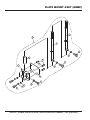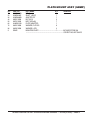
1
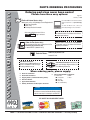
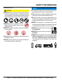
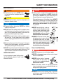
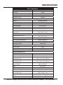
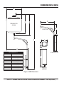
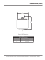
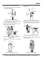
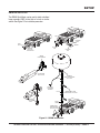
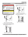
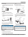
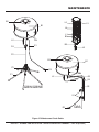
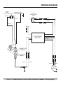
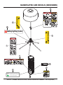
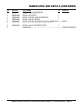
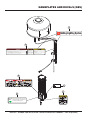
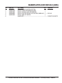
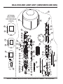
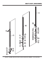
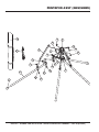
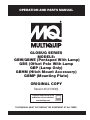
OPERATION AND PARTS MANUAL GLOBUG SERIES MODELS: GBW/GBWE (Pentapod With Lamp) GBS (Offset Pole With Lamp GBP (Lamp Only) GBHM (Hitch Mount Accessory) GBMP (Mounting Plate) ORIGINAL COPY Revision #0 (07/23/09) To find the latest revision of this publication, visit our website at: www.multiquip.com THIS MANUAL MUST ACCOMPANY THE EQUIPMENT AT ALL TIMES. PROPOSITION 65 WARNING PAGE 2 — GLOBUG LIGHTING SYSTEM • OPERATION AND PARTS MANUAL — REV. #0 (07/23/09) TABLE OF CONTENTS GBW/GBWE/GBS/GBP/ GBHM/GBMP Lighting System Proposition 65 Warning ........................................... 2 Table Of Contents .................................................... 3 Parts Ordering Procedures ...................................... 4 Specifications ........................................................ 10 Dimensions (GBW/GBWE) .................................... 11 Dimensions (GBS) ................................................. 12 Dimensions (GBP) ................................................. 13 Footcandle Plot...................................................... 14 General Information ............................................... 15 Components ..................................................... 16-17 Setup ................................................................ 18-22 Operation .......................................................... 23-25 Maintenance ..................................................... 26-31 Wiring Diagram ...................................................... 32 Explanation Of Code In Remarks Column............. 34 Suggested Spare Parts ......................................... 35 Component Drawings Nameplates And Decals (GBW/GBWE) ........... 36-37 Nameplates And Decals (GBS) ........................ 38-39 Balloon And Lamp Assy (GBW/GBWE/GBS) ... 40-41 Mast Assy (GBW/GBWE) ................................. 42-43 Pentapod Assy (GBW/GBWE).......................... 44-45 Pole Assy (GBS) ............................................... 46-47 Hitch Mount Assy (GBHM) ............................... 48-49 Plate Mount Assy (GBMP)................................ 50-51 Terms And Conditions Of Sale — Parts ................ 52 NOTICE Specifications and part numbers are subject to change without notice. GLOBUG LIGHTING SYSTEM • OPERATION AND PARTS MANUAL — REV. #0 (07/23/09) — PAGE 3 www.multiquip.com PARTS ORDERING PROCEDURES Ordering parts has never been easier! Choose from three easy options: Order via Internet (Dealers Only): Best Deal! Effective: January 1st, 2006 If you have an MQ Account, to obtain a Username and Password, E-mail us at: parts@multiquip. com. Order parts on-line using Multiquip’s SmartEquip website! ■ View Parts Diagrams ■ Order Parts ■ Print Specification Information To obtain an MQ Account, contact your District Sales Manager for more information. Use the internet and qualify for a 5% Discount on Standard orders for all orders which include complete part numbers.* Goto www.multiquip.com and click on Order Parts to log in and save! Note: Discounts Are Subject To Change Order via Fax (Dealers Only): All customers are welcome to order parts via Fax. Domestic (US) Customers dial: 1-800-6-PARTS-7 (800-672-7877) Fax your order in and qualify for a 2% Discount on Standard orders for all orders which include complete part numbers.* Note: Discounts Are Subject To Change Order via Phone: Domestic (US) Dealers Call: 1-800-427-1244 Non-Dealer Customers: Contact your local Multiquip Dealer for parts or call 800-427-1244 for help in locating a dealer near you. International Customers should contact their local Multiquip Representatives for Parts Ordering information. When ordering parts, please supply: ❒ ❒ ❒ ❒ ❒ ❒ Dealer Account Number Dealer Name and Address Shipping Address (if different than billing address) Return Fax Number Applicable Model Number Quantity, Part Number and Description of Each Part ❒ Specify Preferred Method of Shipment: ✓ UPS/Fed Ex ✓ DHL ■ Priority One ✓ Truck ■ Ground ■ Next Day ■ Second/Third Day NOTICE All orders are treated as Standard Orders and will ship the same day if received prior to 3PM PST. WE ACCEPT ALL MAJOR CREDIT CARDS! PAGE 4 — GLOBUG LIGHTING SYSTEM • OPERATION AND PARTS MANUAL — REV. #0 (07/23/09) SAFETY INFORMATION Do not operate or service the equipment before reading the entire manual. Safety precautions should be followed at all times when operating this equipment. Failure to read and understand the safety messages and operating instructions could result in injury to yourself and others. Potential hazards associated with the operation of this equipment will be referenced with hazard symbols which may appear throughout this manual in conjunction with safety messages. SAFETY MESSAGES The four safety messages shown below will inform you about potential hazards that could injure you or others. The safety messages specifically address the level of exposure to the operator and are preceded by one of four words: DANGER, WARNING, CAUTION or NOTICE. SAFETY SYMBOLS DANGER Indicates a hazardous situation which, if not avoided, WILL result in DEATH or SERIOUS INJURY. WARNING Indicates a hazardous situation which, if not avoided, COULD result in DEATH or SERIOUS INJURY. CAUTION Indicates a hazardous situation which, if not avoided, COULD result in MINOR or MODERATE INJURY. NOTICE Addresses practices not related to personal injury. GLOBUG LIGHTING SYSTEM • OPERATION AND PARTS MANUAL — REV. #0 (07/23/09) — PAGE 5 SAFETY INFORMATION GENERAL SAFETY CAUTION NEVER operate this equipment without proper protective clothing, shatterproof glasses, respiratory protection, hearing protection, steel-toed boots and other protective devices required by the job or city and state regulations. NEVER operate this equipment when not feeling well due to fatigue, illness or when under medication. NEVER operate this equipment under the influence of drugs or alcohol. NOTICE This equipment should only be operated by trained and qualified personnel 18 years of age and older. Whenever necessary, replace nameplate, operation and safety decals when they become difficult read. Manufacturer does not assume responsibility for any accident due to equipment modifications. Unauthorized equipment modification will void all warranties. NEVER use accessories or attachments that are not recommended by Multiquip for this equipment. Damage to the equipment and/or injury to user may result. ALWAYS know the location of the nearest fire extinguisher. ALWAYS know the location of the nearest first aid kit. ALWAYS check the equipment for loosened threads or bolts before starting. DO NOT use the equipment for any purpose other than its intended purposes or applications. ALWAYS know the location of the nearest phone or keep a phone on the job site. Also, know the phone numbers of the nearest ambulance, doctor and fire department. This information will be invaluable in the case of an emergency. PAGE 6 — GLOBUG LIGHTING SYSTEM • OPERATION AND PARTS MANUAL — REV. #0 (07/23/09) SAFETY INFORMATION LIGHTING SYSTEM SAFETY DANGER NEVER use lighting system in rain, snow or areas of high humidity that could generate electrical storms. WARNING NEVER disconnect any emergency or safety devices. These devices are intended for operator safety. Disconnection of these devices can cause severe injury, bodily harm or even death. Disconnection of any of these devices will void all warranties. CAUTION NEVER attempt service on a running machine. NOTICE To prevent the lighting system from overturning, NEVER use in winds that exceed 22 mph (10 m/s). The lighting system should only be used in temperatures between 23° to 104°F (-5° to 40° C). Failure to comply with these operating parameters could cause the lamp to malfunction and shorten the ballast life. ALWAYS keep the lighting system in proper running condition. Fix damage to lighting system and replace any broken parts immediately. LAMP SAFETY WARNING NEVER attempt to replace lamp with the power on. Always unplug the power cord from the generator or power source when changing the lamp. ALWAYS allow a sufficient amount of time for the lamp to cool before changing. The possibility exists of severe burns. CAUTION NEVER use force when installing the lamp. Excessive force could cause the lamp to break, causing bodily harm. NOTICE NEVER leave any grease or oil residue on lamp surface when replacing or removing lamp. This can create hot spots, reducing the service life of the lamp. ALWAYS make sure lamp surface is clean and dry. ALWAYS replace with MQ recommended type lamp. See parts section of this manual. If applicable, ALWAYS make sure the lamp guard is installed correctly. NEVER deform the lamp guard. NEVER unplug the lamp’s AC power cable during operation. ALWAYS have a trained technician to install and remove lamp or replace any damaged fixture wiring. ALWAYS store equipment properly when it is not being used. Equipment should be stored in a clean, dry location out of the reach of children and unauthorized personnel. GLOBUG LIGHTING SYSTEM • OPERATION AND PARTS MANUAL — REV. #0 (07/23/09) — PAGE 7 SAFETY INFORMATION BALLOON SAFETY WARNING To prevent serious burns, NEVER touch or unzip the balloon envelope when the lamp is on. CAUTION ALWAYS keep the balloon away from sharp objects and excessive amounts of heat. NOTICE To prevent balloon deformation, NEVER use lighting system in strong winds. DO NOT place the balloon inside its protective cover until the lamp has had a sufficient amount of time to cool down. This will prevent the balloon’s nylon cover from being burned (touching the lamp surface). ALWAYS place the balloon inside its protective cover after each use. This will prolong the life of the balloon material, keeping it protected from harsh environmental elements. Replace balloon immediately if damaged. A damaged balloon will not inflate properly, and may become more damaged by touching the hot lamp surface. DO NOT use excessive force when zipping and unzipping the balloon. Be gentle with the zipper mechanism. If the zipper is broken, the balloon will become unusable. GENERATOR SAFETY If using a generator to power lighting system, refer to applicable generator manual safety information section. ELECTRICAL SAFETY DANGER Lighting system is equipped with a ground pin on the power plug. For your protection, ALWAYS complete the grounding path. NEVER insert the AC power plug into a 2-prong receptacle to operate lighting system. When applying power to the lighting system, ALWAYS connect the AC power plug to a 3-prong receptacle that is grounded. The possibility exists of electrical shock, electrocution and even death if the lighting system is not grounded. NEVER operate lighting system or handle any electrical equipment while standing in water, while barefoot, while hands are wet or in the rain. A dangerous electrical shock could occur, causing severe bodily harm or even death. ALWAYS make sure the area above the lighting system is open and clear of overhead power lines and other obstructions. Contact with overhead power lines or other obstructions could result in equipment damage, electrical shock, electrocution and even death. Power Cord/Cable Safety DANGER NEVER let power cords or cables lay in water. NEVER use damaged or worn cables or cords. Inspect for cuts in the insulation NEVER grab or touch a live power cord or cable with wet hands. The possibility exists of electrical shock, electrocution or death. Make sure power cables are securely connected. Incorrect connections may cause electrical shock and damage to the lighting system. NOTICE ALWAYS make certain that proper power or extension cord has been selected for the job. See Cable Selection Chart in this manual. PAGE 8 — GLOBUG LIGHTING SYSTEM • OPERATION AND PARTS MANUAL — REV. #0 (07/23/09) SAFETY INFORMATION LOADING AND UNLOADING Cart Type - No Lifiting Hook Cart Type - With Lifiting Hook If lighting system is not equipped with a transport lifting hook and the mast is removable, refer to the following safety information. If lighting system is equipped with a transport lifting hook, refer to the following safety information. CAUTION Before lifting, make sure that the mast and lamp are removed as described in the manual. Before lifting, make sure that lighting system parts are not damaged and screws are not loosened or lost. The cart can be safely lifted by two persons to the transport vehicle. ALWAYS make sure crane or lifting device has been properly secured to lifting hook of the equipment. TRANSPORTING SAFETY NEVER lift the equipment while lighting system is running. Make sure the mast is completely lowered before lifting the lighting system. Use adequate lifting cable (wire or rope) of sufficient strength. Use one point suspension hook and lift straight upwards. NOTICE When transporting the lighting system, if applicable, always place in stow position and place mast in its carrying case. ALWAYS remove balloon/lamp assembly from the mast when transporting lighting system. This will prevent damage to the bulb due to vibration. NEVER leave the balloon/lamp exposed during transport. Exposure to excess wind or rain could damage the balloon’s nylon cover. ALWAYS place balloon inside its protective cover during transport. Be sure the cover is secured tightly around the balloon/lamp assembly. Never allow any person or animal to stand underneath the equipment while lifting. DO NOT lift machine to unnecessary heights. GLOBUG LIGHTING SYSTEM • OPERATION AND PARTS MANUAL — REV. #0 (07/23/09) — PAGE 9 SPECIFICATIONS Table 1. Specifications Model GBW/GBWE/GBS/GBP Input Voltage 120 VAC Max. Current 9.3 A @ 120 V Frequency Appropriate Generator 50-60 Hz Single-Phase 1700 Watts Lamp Lamp Type Total Luminous Flux 1,000 Watt Metal Halide 107,000 lm Standard Balloon Diameter 47.2 in (1200 mm) Light Coverage (360°) 90 ft (27.4 meters) Lamp Surface Temperature (Longitudinal) 476.6° F (247° C) max Lamp Surface Temperature (Transversal) 417.2° F (214° C) max Dimensions (L x W x H) Storage (Lamp) 8.7x 8.7 x 40 in (700 x 1,023 x 1,212 mm) BALLOON Balloon Dimensions (L x W x H) Balloon Material Balloon Heat-Resisting Temperature 47.2 x 47.2 x 28.3 in. (1200 x 1200 x 720 mm) Polyester 320-356° F (160-180° C) Internal Balloon Temperature 126° F (52° C) Balloon Water Resistance 1,500 mm H2O FAN MOTOR Fan Motor Voltage 100 VAC Fan Motor Current 0.45/0.55 A Fan Motor Pressure .347/.372 kPA (.050/.054 psi) PENTAPOD (GBW/GBWE only) Outriggers Mast - Number of Stages 5 3 (air shock absorbers) GBW Dimensions (L x W x H) Upper Working Position 64.6 x 67.9 x 107 to 158.3 in (1,640 x 1,725 x 2,720 to 4,020 mm) GBWE Dimensions (L x W x H) Upper Working Position 64.6 x 67.9 x 107 to 193.3 in (1,640 x 1,725 x 2,720 to 4,910 mm) Dimensions (L x W x H) Storage (Pentapod) Weight 7.9 x 8.7 x 28.3 in (200 x 220 x 720 mm) 56 lb (25.6 kg) OFFSET POLE (GBS Only) Mast - Number of Stages 2 stages (offset and straight pole) Dimensions (L x W x H) Upper Working Position 47.2 x 49.6 x 99 in (1,200 x 1,260 x 2,515 mm) Dimensions (L x W x H) Storage Straight Pole: 35 in (890 mm) Offset Pole: 26.9 x 16.7 x 2 in (683 x 425 x 52 mm) Weight 34 lb (15.4 kg) PAGE 10 — GLOBUG LIGHTING SYSTEM • OPERATION AND PARTS MANUAL — REV. #0 (07/23/09) DIMENSIONS (GBW/GBWE) D B A C E Figure 1. GBW/GBWE Dimensions Reference Letter A (GBW) A (GBWE) B C D E Table 2. GBW Dimensions Description Total Max. Height (with Standard Balloon) Total Max. Height (with Standard Balloon) Standard Balloon Height Mast Height (without Balloon) Standard Balloon Diameter Mast Height (Stowed) Dimension inches (mm) 158.3 (4,020) 193.3 (4,910) 28.3 (720) 130 (3,302) 47.2 (1,200) 28.3 (720) GLOBUG LIGHTING SYSTEM • OPERATION AND PARTS MANUAL — REV. #0 (07/23/09) — PAGE 11 DIMENSIONS (GBS) B GB36 BALLOON SHOWN C F D G OFFSET POLE I E H J A Table 3. GBS Dimensions Reference Letter Dimension inches (mm) A 44.68 (1,135) B 35.43 (900) C 33.46 (850) D 38.38 (975) E 85.62 (2,175) F 26.88 (683) G 16.73 (425) H 39.37 (1,000) I 8.66 (220) J 7.87 (200) K 28.34 (720) STRAIGHT POLE K BALLOON ASSEMBLY Figure 2. GBS Dimensions PAGE 12 — GLOBUG LIGHTING SYSTEM • OPERATION AND PARTS MANUAL — REV. #0 (07/23/09) DIMENSIONS (GBP) A B Figure 3. GBP Dimensions Table 4. GBP Dimensions Reference Letter Dimension inches (mm) A 35.43 (900) B 33.46 (850) GLOBUG LIGHTING SYSTEM • OPERATION AND PARTS MANUAL — REV. #0 (07/23/09) — PAGE 13 FOOTCANDLE PLOT .25 .5 1 2 5 VALUES LISTED AS FOOTCANDLES 10 SCALE: 1 GRID = 50 FT. (15.24 METERS) Figure 4. Illumination Range PAGE 14 — GLOBUG LIGHTING SYSTEM • OPERATION AND PARTS MANUAL — REV. #0 (07/23/09) GENERAL INFORMATION The Multiquip GloBug GBW/GBWE, GBS, GBP are general- purpose, portable, glare-free lighting systems intended for emergency and remote lighting needs. It is universally adaptable to all AC power supplies and accepts 50/60 Hz, 100-240 V. The GBP (also included with the GBW/GBWE and GBS) provides 360° glarefree illumination. The balloon is selfinflating and easy to install and inflate in less than 20 seconds. It uses a single 1,000 watt lamp with pure white light for maximum illumination with a light coverage of up to 150 feet. The balloon is self-inflating and easy to install and inflate in less than 20 seconds. Ampere Volts Rating 115V Range 230V 0-2 2-3 3-4 4-5 5-6 6-8 8 - 10 10 - 12 12 - 14 14 - 16 16 - 18 18 - 20 25 Ft. 50 Ft. 18 18 18 18 18 18 18 16 16 16 14 14 The GBW/GBWE has a three-stage mast that extends to a height of up to 13 feet and 2 inches. The GBW/GBWE has five outriggers (pentapod) for great stabilization. The GBS is designed to be attached to an external piece of equipment such as a paver. The system is easy to assemble and includes poles and mounting brackets. The GBHM Hitch Mount can be used to attach a GBP to a hitch on a truck. The GBMP Plate Mount can be used to attach a GBP to a trailer. If an extension cord is necessary to connect to a power source, refer to Table 5 to select the proper length. Table 5. Extension Cord Gauge Selection Length of Cord in Feet 50 Ft. 100 Ft. 150 Ft. 200 Ft. 250 Ft. 100 Ft. 200 Ft. 300 Ft. 400 Ft. 500 Ft. 18 18 16 16 14 18 16 14 14 12 18 16 14 12 12 18 14 12 12 10 16 14 12 10 10 16 12 10 10 8 14 12 10 8 8 14 10 8 8 6 12 10 8 6 6 12 10 8 6 6 12 8 8 6 4 12 8 6 6 4 300 Ft. 600 Ft. 14 12 10 10 8 6 6 6 6 4 4 4 400 Ft. 800 Ft. 12 10 10 8 8 6 6 4 4 4 2 2 500 Ft. 1000 Ft. 12 10 8 8 6 6 4 4 2 2 2 2 GLOBUG LIGHTING SYSTEM • OPERATION AND PARTS MANUAL — REV. #0 (07/23/09) — PAGE 15 COMPONENTS GBP 1 13 2 3 12 4 19 20 14 18 11 5 10 17 16 9 15 8 7 6 GBW/GBWE 21 22 25 GBHM GBWE/GBHM/ GBMP ONLY 28 27 26 24 GBMP 23 5 GBS Figure 5. GBW/GBWE/GBS/GBP Components PAGE 16 — GLOBUG LIGHTING SYSTEM • OPERATION AND PARTS MANUAL — REV. #0 (07/23/09) COMPONENTS Figure 5 shows the location of the controls and components for the GBW Lighting System. The functions of each control is described below: 1. Balloon Cover — Stores balloon when GBW is not in use. Allow a sufficient amount of time for the lamp to cool down before storing balloon. Possibility exists of balloon getting burned. 2. Balloon — Made of heat resistant polyester, with a diameter of 47.2 inches (1,200 mm). Balloon is selfinflating and inflates in less than 20 seconds. 3. Velcro — Used to easily attach optional message strip to the balloon. 4. Buckle — Used to hold the balloon together when storing inside the cover. 5. AC Power Cable — Connects to the AC power source (generator) on one end and to the lamp connector on the other end with quick-disconnect connector. 6. Pentapod — Supports and holds up the GBW. 7. Locking Clamps — To secure the generator to the cart platform, place clamps around the pipe frame of the generator. Tighten securely to prevent movement. 8. Stay — Supports the mast against the pentapod. 9. Mast — This mast is comprised of three separate stages. The mast can be raised in excess of 8 feet (without balloon). When raising the mast, always be on the lookout for overhead obstructions. 10. Mast Bolt — Loosen to raise mast and tighten to keep the mast in place when raised to the desired height. 11. AC Power Cable Connector — Connect this quickdisconnect plug to the balloon connector. 12. Message Strip (OPTIONAL) — a 12 x 43 inch message strip (GBBALD1) may be attached to the balloon. The message strip can be purchased separately. 14. Lamp Holder — Holds lamp in place. Lamp is screwed into socket. 15. Balloon Connector — Connect this connector to the AC power cable connector. 16. Lamp/Balloon Bolt — Used to tighten mast when attached to the lamp/balloon assembly. 17. Fan Motor (Blower) — Inflates the balloon as soon as power is applied. 18. Lamp — 1000 watt metal halide bulb with pure white light for maximum illumination. 19. Lamp Guard — Protects the lamp from being hit by objects and the balloon from touching the lamp. 20. Carrying Case — Use this case to store the pentapod when transporting or when not in use. 21. Offset Pole — Supports lamp assembly when attached to the straight pole. 22. Knob — Secures the offset pole to the straight pole when tightened. 23. Straight Pole — Used in conjunction with the offset pole to support the lamp assembly. 24. Clamps — Used to attach the straight pole to an external support. These clamps must be tightened securely to prevent the light assembly from falling off. 25. Extension Pole — Extends mast height by 40 inches (GBWE). For GBHM and GBMP, 2 poles are included to support the desired balloon assembly. 26. Hitch Mount Assembly — Used to attach balloon assembly to a hitch on a truck or similar vehicle. 27. Plate Mount Assembly — Used to attach balloon assembly to a trailer or similar vehicle. 28. Plate — Attaches directly to a trailer to hold plate mount assembly. 13. Zipper — Zips up balloon to completely close it when lamp is in place. GLOBUG LIGHTING SYSTEM • OPERATION AND PARTS MANUAL — REV. #0 (07/23/09) — PAGE 17 SETUP GBW/GBWE SETUP 1. Set the GBW on a firm level surface where there is enough space around the pentapod for the outriggers to be deployed. upper or lower position. Placing the lock in the upper position will provide 1 foot (305 mm) more height. See Figure 8. LATCH 2. Remove the pentapod from the carrying case. The pentapod outriggers are secured together with a strap. See Figure 6. Squeeze both tabs on the buckle to unlock strap and release pentapod outriggers. UPPER POSITION LOWER POSITION SQUEEZE STRAP Figure 8. Securing the Pentapod 5. For the GBWE, attach the extension pole to the top of the mast as shown in Figure 9. EXTENSION POLE BUCKLE PENTAPOD OUTRIGGER Figure 6. Releasing Pentapod Buckle 3. Lift mast up and deploy the pentapod as shown in Figure 7. BOLT DEPLOY PENTAPOD Figure 9. Attaching Extension Pole (GBWE) 6. To improve stability and prevent tipping of the lighting system, place sand bags on the outriggers or similar weight on the weight hook as shown in Figure 10. WEIGHT HOOK Figure 7. Deploying the Pentapod SANDBAG WEIGHT 4. With pentapod fully deployed, hook the latch to lock the pentapod in place. The latch can be hooked in the Figure 10. Sand Bags and Weight PAGE 18 — GLOBUG LIGHTING SYSTEM • OPERATION AND PARTS MANUAL — REV. #0 (07/23/09) SETUP GBS SETUP 1. Attach one of the clamps that come with the GBS to the external support pole. The clamps may be attached to vertical, horizontal, or angled pole. See Figure 11. 4. Attach the straight pole to the clamps. Tighten locknuts on both clamps. See Figure 13. STRAIGHT POLE VERTICAL EXTERNAL SUPPORT POLE CLAMPS CLAMP LOCKNUT Figure 13. Straight Pole Attachment WARNING Always securely tighten the locknuts when assembly is used to prevent the lighting system from falling off which can cause injury or equipment damage. CLAMP ANGLED EXTERNAL SUPPORT POLE HORIZONTAL EXTERNAL SUPPORT POLE LOCKNUT 5. Place the offset pole (or an optional straight pole, if desired) on top of the straight pole. Tighten knob or bolt securely. See Figure 14. OFFSET POLE Figure 11. Clamp Attachment STRAIGHT POLE 2. Using a 19 mm wrench, tighten the locknut securely. See Figure 11. 3. Attach the other clamp to the external support pole about 7 inches (140 mm) lower than the previously installed clamp. See Figure 12. If using horizontal external support poles, a second pole is needed. BOLT KNOB Figure 14. Offset Pole Attachment 7.0 INCHES (140 MM) WARNING Always securely tighten the knob on the offset or the bolt on the straight pole when assembly is used to prevent the lighting system from falling off which can cause injury or equipment damage. Figure 12. Distance Between Clamps GLOBUG LIGHTING SYSTEM • OPERATION AND PARTS MANUAL — REV. #0 (07/23/09) — PAGE 19 SETUP BALLOON INSTALLATION (GBW/GBWE/GBS) 1. Insert the balloon assembly into the mast. Tighten the T-bolt securely. See Figure 15. 5. Connect the power cable to the lamp cable connector. See Figure 18. LAMP CABLE CONNECTOR BALLOON PROTECTIVE COVER POWER CABLE CONNECTOR T-BOLT MAST Figure 15. Installing the Balloon Figure 18. Connecting the Power Cable 2. Unsnap the three buttons on the bottom of the balloon cover and unzip the cover. See Figure 16 6. Secure the power cable by hooking it to the eyelet on the bottom of the balloon as shown in Figure 19. 3. Remove the AC Power Cable from the inside pocket of the balloon cover. See Figure 16. AC POWER CABLE ZIPPER CABLE HOOK BUTTON Figure 19. Securing Cable with Hook Figure 16. Removal of AC Power Cable from Balloon Cover 7. Release the buckle on the belt holding the balloon together. See Figure 20. 4. Fold the balloon cover into itself and zip it up. See Figure 17. FOLD PROTECTIVE COVER INTO ITSELF ZIPPER BALLOON FULLY EXPOSED Figure 17. Folding Balloon Cover BUCKLE Figure 20. Releasing Buckle PAGE 20 — GLOBUG LIGHTING SYSTEM • OPERATION AND PARTS MANUAL — REV. #0 (07/23/09) SETUP GBHM INSTALLATION The GBHM Hitch Mount can be used to attach a balloon/ lamp assembly (GBP) to the hitch of a truck or similar vehicle. See Figure 21 for installation procedure. NUT LOCKING BOLT BALL HITCH INSTALL COTTER PIN REMOVE BOLT OR COTTER PIN LOCKING PIN GBHM HITCH MOUNT SLIDE ONTO BALL HITCH POLE T-HANDLE TURN CLOCKWISE TO LOCK CONNECT TO POWER SOURCE POLE INSTALL NUT AND BOLT INSERT BOLT AND TIGHTEN NUT TO LOCK SHAFT (JOINT) INSERT BOLT AND TIGHTEN NUT TO LOCK Figure 21. GBHM Installation GLOBUG LIGHTING SYSTEM • OPERATION AND PARTS MANUAL — REV. #0 (07/23/09) — PAGE 21 SETUP GBMP INSTALLATION The GBMP Plate Mount is attached to a trailer or similar vehicle to support the balloon/lamp assembly (GBP). See Figure 22 for installation procedure T-HANDLE TURN CLOCKWISE TO LOCK POLE CONNECT TO POWER SOURCE POLE INSERT BOLT AND TIGHTEN NUT TO LOCK TRAILER FRAME DRILL 9/16” DIA. HOLE MOUNTING BRACKET MOUNTING BOLTS SUPPORT PLATE SHAFT (JOINT) NUT INSERT BOLT AND TIGHTEN NUT TO LOCK FLAT WASHER LOCK FLAT WASHER WASHER Figure 22. GBMP Installation PAGE 22 — GLOBUG LIGHTING SYSTEM • OPERATION AND PARTS MANUAL — REV. #0 (07/23/09) OPERATION RAISING THE MAST (GBW/GBWE) DANGER ALWAYS make sure the area above the lighting system is open and clear of overhead power lines and other obstructions. Contact with overhead power lines or other obstructions could result in equipment damage, electrical shock, electrocution and even death. LOWERING THE MAST (GBW/GBWE) 1. Loosen the T-bolt holding the second mast and push mast all the way down. Tighten T-bolt securely. See Figure 25. SECOND MAST CAUTION When raising or lowering the mast, keep hands and fingers clear of the mast sections to prevent hand and fingers from getting pinched. Figure 25. Lowering Second Mast 1. Raise the second mast to the desired height and tighten the T-bolt securely. See Figure 23. 2. Push the lock/release tab on the third mast to release it and lower third mast. See Figure 26. T-BOLT SECOND MAST THIRD MAST LOCK/ RELEASE TAB T-BOLT Figure 26. Lowering Third Mast Figure 23. Raising the Second Mast 2. To raise the mast higher, raise the third mast until the lock/release tab pops out. The tab will automatically rest on the second mast. See Figure 24. THIRD MAST LOCK/ RELEASE TAB Figure 24. Raising the Third Mast GLOBUG LIGHTING SYSTEM • OPERATION AND PARTS MANUAL — REV. #0 (07/23/09) — PAGE 23 OPERATION turn off. APPLYING POWER 1. If using a portable generator, plug the AC power cable to the 120 VAC receptacle on the generator used. See Figure 27. 120 VAC RECEPTACLE 20A POWER CABLE SHUTTING DOWN LAMP ONLY 1. Unzip the bottom of the balloon. See Figure 29. TYPICAL GENERATOR FRONT PANEL BALLOON 120V Figure 27. Connecting to Generator 2. Start the generator as indicated in the generator manual. 3. If using power source other than a portable generator, plug the AC power cord to a 120 VAC, receptacle. See Figure 28. Figure 29. Unzipping Balloon 2. Push the button above the LED with a blunt object for three seconds as shown in Figure 20. LED will turn red and the lamp will turn off. The balloon will remain deployed. PUSH WITH BLUNT OBJECT POWER CABLE RECEPTACLE EXTERNAL SINGLE-PHASE (120 VAC) POWER SOURCE Figure 28. Connecting to 120 VAC Receptacle 4. The balloon will start to inflate as soon as power is applied and the lamp will turn on. NOTICE If the power cable is accidentally unplugged from the power source, wait three to five minutes before reconnecting the power. This will allow time for the fan to reset and ensure balloon will inflate properly when power is reconnected. LED Figure 30. Turning Off Lamp Only NOTICE To turn lamp back on, unplug the power cable from the power source. Wait three to five minutes before reconnecting the power. Reconnect the power cable and the lamp should turn on and the balloon will inflate. SHUTDOWN 1. Turn off the power switch of the generator. 2. Disconnect the AC power cable from the generator. The balloon should start to deflate and the lamp will PAGE 24 — GLOBUG LIGHTING SYSTEM • OPERATION AND PARTS MANUAL — REV. #0 (07/23/09) OPERATION STORAGE (GBW/GBWE) Before storing the GBW/GBWE Lighting System, perform the following steps. 9. Continue pulling upward on the mast until all the pentapod legs are fully retracted and are stowed. See Figure 32. NOTICE STRAP Allow about 15 to 20 minutes for the lamp to cool down before storing the GBW/GBWE. The possibility exists of the balloon getting burned if it touches a hot lamp. 1. Disconnect the lamp connector from the AC power cable. PENTAPOD STOWED 2. Unhook the AC power cable from the eyelet at the bottom of the balloon. 3. Make sure the mast is completely lowered as described in LOWERING THE MAST section. 4. Lock the buckle to secure the balloon together. Figure 32. Stowing the Pentapod 10. Once pentapod legs are all in stow position, wrap strap around all five legs and secure by locking the buckle. See Figure 33. 5. Unzip the zipper on the protective cover and pull down cover over the balloon/lamp assembly. 6. Place the AC power cable in the pocket inside the protective cover and attach velcro tabs. 7. Loosen the T-bolt on the balloon/lamp assembly and lift balloon/lamp assembly from the mast. BUCKLE STRAP 8. Lift mast while pulling up strap (Figure 31). LATCH Figure 33. Locking Up Stowed Pentapod UPPER POSITION LOWER POSITION 11. Place the stowed pentapod inside the carrying case. See Figure 34. CARRYING CASE Figure 31. Unlocking the Latch STOWED PENTAPOD Figure 34. Storing in Carrying Case GLOBUG LIGHTING SYSTEM • OPERATION AND PARTS MANUAL — REV. #0 (07/23/09) — PAGE 25 MAINTENANCE 3. Remove the lamp guard. REPLACING LAMP DANGER Never attempt to replace lamp in a wet place. The possibility exists of electric shock. 4. Press the tabs on the lamp holder and push up lamp holder to release it from lamp. See Figure 37. WARNING Always allow sufficient time for the lamp to cool down before replacing. The possibility exists of severe burns if hot lamp is touched. \ LAMP HOLDER LAMP HOLDER STOPPER CAUTION Always shutdown power source and remove balloon assembly from mast when replacing a broken lamp. Utmost care should be taken in handling broken lamp. The possibility exists of serious injury from handling a broken lamp. Figure 37. Lamp Holder 5. Remove the lamp from the lamp socket by turning lamp counterclockwise. See Figure 38. 1. Unzip the zipper at the bottom of the balloon and roll the balloon up to expose the lamp. See Figure 35. LAMP BALLOON LAMP SOCKET ZIPPER Figure 38. Removing Lamp Figure 35. Exposing Balloon 6. Install new lamp into socket and turn lamp in a clockwise direction until tight. See Figure 39. 2. Release the lamp guard locking tabs. See Figure 36. LAMP LAMP SOCKET LAMP GUARD LOCK TAB Figure 39. Installing New Lamp Figure 36. Removing Lamp Guard PAGE 26 — GLOBUG LIGHTING SYSTEM • OPERATION AND PARTS MANUAL — REV. #0 (07/23/09) MAINTENANCE 3. Slide in the new replacement balloon over the top of the lamp guard assembly. See Figure 42. NOTICE Do not use excessive force when screwing the lamp to prevent lamp from breaking. 7. Secure lamp holder on top of the lamp. 8. Reinstall lamp guard. 9. Pull down balloon and zip the bottom zipper to cover lamp. INSTALL NEW BALLOON REPLACING BALLOON 1. Unzip the top and bottom of the balloon. See Figure 40. Figure 42. Replacing Balloon 4. Zip up the top and bottom of the new balloon. See Figure 43. UNZIP TOP AND BOTTOM ZIPPERS BALLOON ZIP UP NEW BALLOON Figure 40. Unzipping Balloon 2. Slide out the old or worn balloon over the top of the lamp guard assembly. See Figure 41. Figure 43. Zipping Up New Balloon REMOVE OLD BALLOON Figure 41. Removing Old Balloon GLOBUG LIGHTING SYSTEM • OPERATION AND PARTS MANUAL — REV. #0 (07/23/09) — PAGE 27 MAINTENANCE FILTER REPLACEMENT 5. Install a new filter and reinstall the air plate. 1. Remove the balloon as described in the STORAGE section. 6. Turn the three locking tabs inwards to lock the air plate in place. See Figure 46. 2. Turn the balloon/lamp assembly upsidedown to access the filter. See Figure 44. LOCK TAB AIR PLATE LOCKING TAB Figure 46. Locking Air Plate Figure 44. Accessing Filter 3. Turn the three locking tabs outwards to release the air plate. See Figure 44. 4. Remove the air plate and filter. See Figure 45. AIR PLATE FILTER Figure 45. Filter Removal PAGE 28 — GLOBUG LIGHTING SYSTEM • OPERATION AND PARTS MANUAL — REV. #0 (07/23/09) MAINTENANCE SYMPTOM Lamp does not light. Lamp only lights for a short time. Balloon does not inflate. Table 6. Troubleshooting POSSIBLE PROBLEM Is plug disconnected? Is generator power switched off? Is lamp loose? Is power connector disconnected or loose? Are any other electric appliances (other than light tower) plugged into power source? Is model of lamp incompatible? Is lamp not cool enough to light again? (Interval of 5 to 10 minutes is required before turning on lamp again) Is ambient temperature too high (more than 104° F (40° C)? Is fan motor (blower) not working properly? Is balloon envelope defective? SOLUTION Plug in correctly. Turn on switch. Screw lamp securely into socket. Connect disconnected connector. Unplug all other appliances. Use genuine MQ lamp. Wait for lamp to cool down. Move lamp where there is proper ventilation. Check and repair fan motor (blower). Repair or replace balloon envelope. GLOBUG LIGHTING SYSTEM • OPERATION AND PARTS MANUAL — REV. #0 (07/23/09) — PAGE 29 MAINTENANCE B2 L5 B1 L3 L4 L1 B3 L2 B4 P4 E1 B5 L2 P2 B2 P3 B1 E2 B4 P1 S3 L2 E1 S4 S2 GBW/GBWE S1 E2 GBS Figure 47. Maintenance Check Points PAGE 30 — GLOBUG LIGHTING SYSTEM • OPERATION AND PARTS MANUAL — REV. #0 (07/23/09) MAINTENANCE Table 7. Periodic Check and Maintenance FIGURE PART CHECK ITEM L1 Lamp (Base) Lamp base loose? L2 Connector Cable disconnected or loose? Lamp L3 Lamp Holder Lamp holder loose? L4 Pipe Frame Pipe Frame skewed L5 Lamp Defective lamp? B1 Balloon (Envelope) Defective or dirty? B2 Zipper Broken? Balloon B3 Fan Motor (Blower) Not working properly? B4 Buckle Broken? B5 T-handle bolt (balloon) Broken? P1 Pentapod Damaged or Not Working Properly? P2 Mast Damaged or Not Working Properly? Pentapod P3 Latch Damaged? P4 Stopper Damaged? E1 Power cable Defective or worn cable? Electric E2 Plug Damaged? S1 Clamp Damaged? S2 Straight Pole Damaged or Skewed? Offset Pole S3 Offset Pole Damaged or Skewed? S4 Knob Loose? • — Check daily # — Every 20 hours $ — Every 100 hours SOLUTION Screw in securely. • Connect securely. • Replace. # Replace. & Replace. • Replace. • Replace. • Repair or replace. $ Replace. $ Replace. • Replace. # Replace. # Replace. • Replace. • Replace. • Replace. # Replace. • Replace. $ Replace. $ Tighten Securely. • & — Every 500 hours GLOBUG LIGHTING SYSTEM • OPERATION AND PARTS MANUAL — REV. #0 (07/23/09) — PAGE 31 WIRING DIAGRAM POWER CABLE (120 VAC INPUT) GRN/YEL 10 AWG 1000 WATT METAL HALIDE LAMP G LINE NEUTRAL RED BLACK WHITE BLACK WHITE WHITE GRN/YEL BLACK WHITE ELECTRONIC BALLAST RED BLACK 3 GRN/YEL 1 BLK 1 FRONT VIEW 2 BLK 2 CONNECTOR (FEMALE) CONNECTOR (MALE) TABLE 3 REFERENCE DESIGNATIONS BLACK WHITE BLACK GRN/YEL RED FAN MOTOR PAGE 32 — GLOBUG LIGHTING SYSTEM • OPERATION AND PARTS MANUAL — REV. #0 (07/23/09) NOTES GLOBUG LIGHTING SYSTEM • OPERATION AND PARTS MANUAL — REV. #0 (07/23/09) — PAGE 33 EXPLANATION OF CODE IN REMARKS COLUMN The following section explains the different symbols and remarks used in the Parts section of this manual. Use the help numbers found on the back page of the manual if there are any questions. NOTICE The contents and part numbers listed in the parts section are subject to change without notice. Multiquip does not guarantee the availability of the parts listed. SAMPLE PARTS LIST NO. 1 2% 2% 3 4 PART NO. PART NAME QTY. REMARKS 12345 BOLT .....................1 .....INCLUDES ITEMS W/% WASHER, 1/4 IN. ..........NOT SOLD SEPARATELY 12347 WASHER, 3/8 IN. ..1 .....MQ-45T ONLY 12348 HOSE ..................A/R ...MAKE LOCALLY 12349 BEARING ..............1 .....S/N 2345B AND ABOVE NO. Column QTY. Column Numbers Used — Item quantity can be indicated by a number, a blank entry, or A/R. A/R (As Required) is generally used for hoses or other parts that are sold in bulk and cut to length. A blank entry generally indicates that the item is not sold separately. Other entries will be clarified in the “Remarks” Column. REMARKS Column Some of the most common notes found in the “Remarks” Column are listed below. Other additional notes needed to describe the item can also be shown. Assembly/Kit — All items on the parts list with the same unique symbol will be included when this item is purchased. Unique Symbols — All items with same unique symbol Indicated by: “INCLUDES ITEMS W/(unique symbol)” (@, #, +, %, or >) in the number column belong to the same assembly or kit, which is indicated by a note in the “Remarks” column. Serial Number Break — Used to list an effective serial number range where a particular part is used. Duplicate Item Numbers — Duplicate numbers indicate multiple part numbers, which are in effect for the same general item, such as different size saw blade guards in use or a part that has been updated on newer versions of the same machine. NOTICE When ordering a part that has more than one item number listed, check the remarks column for help in determining the proper part to order. PART NO. Column Numbers Used — Part numbers can be indicated by a number, a blank entry, or TBD. TBD (To Be Determined) is generally used to show a part that has not been assigned a formal part number at the time of publication. A blank entry generally indicates that the item is not sold separately or is not sold by Multiquip. Other entries will be clarified in the “Remarks” Column. Indicated by: “S/N XXXXX AND BELOW” “S/N XXXX AND ABOVE” “S/N XXXX TO S/N XXX” Specific Model Number Use — Indicates that the part is used only with the specific model number or model number variant listed. It can also be used to show a part is NOT used on a specific model or model number variant. Indicated by: “XXXXX ONLY” “NOT USED ON XXXX” “Make/Obtain Locally” — Indicates that the part can be purchased at any hardware shop or made out of available items. Examples include battery cables, shims, and certain washers and nuts. “Not Sold Separately” — Indicates that an item cannot be purchased as a separate item and is either part of an assembly/kit that can be purchased, or is not available for sale through Multiquip. PAGE 34 — GLOBUG LIGHTING SYSTEM • OPERATION AND PARTS MANUAL — REV. #0 (07/23/09) SUGGESTED SPARE PARTS GBW/GBWE/GBS/GBP LIGHTING SYSTEM 1 to 3 units Qty. P/N Description 2............E000077600 .........LAMP 2............A300168900 .........E BALLAST ASSY 2............A100057000 .........BALLOON CLOTH CP 3............A300155100 .........FILTER 1............1654000230..........BALLOON PATCH KIT NOTICE Part numbers on this Suggested Spare Parts list may supersede/replace the part numbers shown in the following parts lists. GLOBUG LIGHTING SYSTEM • OPERATION AND PARTS MANUAL — REV. #0 (07/23/09) — PAGE 35 NAMEPLATES AND DECALS (GBW/GBWE) 1 To prevent breaking, NEVER use in strong winds that makes balloon deformed considerably. the lighting system. 3 8 A-4001938-00 GloBug Lighting System TM 2 WORKSTAND DEPLOYMENT 7 A-4001941-00 6 9 MODEL SERIAL NO. 4 5 Lamp OFF Push the button in the hole with a small switch flat-blade screwdriver (or similar tool) for 3 seconds. LED will turn green. A-4001940-00 PAGE 36 — GLOBUG LIGHTING SYSTEM • OPERATION AND PARTS MANUAL — REV. #0 (07/23/09) NAMEPLATES AND DECALS (GBW/GBWE) NO. 1 2 3 4 5 6 7 8 9 PART NO. A400193800 DCL1262 A400194300 A400194000 A400193900 A400166800 A400194100 A400193300 PART NAME QTY. REMARKS DECAL; GLOBUG INFORMATION 1 DECAL; LATCH (RIGHT) 1 DECAL; LATCH (LEFT) 1 DECAL; CAUTION, LAMP INFORMATION 1 DECAL; LAMP OFF SWITCH 1 DECAL; ELECTRIC SHOCK, HIGH VOLTAGE, BURN HAZ....1 ....... DCL1261 DECAL; DANGER, WORKSTAND DEPLOYMENT 1 DECAL; GLOBUG LIGHTING SYSTEM 1 NAMEPLATE............................................................................1 ....... CONTACT MQ PARTS GLOBUG LIGHTING SYSTEM • OPERATION AND PARTS MANUAL — REV. #0 (07/23/09) — PAGE 37 NAMEPLATES AND DECALS (GBS) 1 GloBug Lighting System TM 2 NEVER operate any of the GloBug lighting systems or handle any electrical equipment while standing in water, while barefoot, while hands are wet, or in the rain. A dangerous electrical shock could occur causing Severe Bodily Harm or even Death ! NEVER disconnect the connector when power is applied. The possibility exists of Electrical shock or equipment damege. Make sure the power cable from the generator is connected to the lamp power cable securely. A loose connection may cause a short circuit. ALWAYS turn OFF generator before performing maintenance. To prevent breaking, NEVER use in strong winds that makes balloon deformed considerably. To avoid accident or injury NEVER exceed a travel speed of 6 MPH when using lighting system on mobile equipment. To avoid accident or injury ALWAYS make certain hardware is securely fastened on pipe clamps. To prevent burns, NEVER touch lamp while lamp is on. Lamp surface gets extremely hot! ALWAYS allow sufficient time for lamp to cool down before touching. To avoid injury, you MUST read and understand operator's manual before using this machine. Once lamp is turned OFF, Allow lamp to cool down before turning back on. It will take about 5 minutes before lamp can be turned back on. ALWAYS disconnect the AC power cable from generator first, before shutting down generator. ALWAYS turn on generator first,before connecting the AC power cable to the generator. To prevent the lighting system from breaking, NEVER use in strong winds that makes balloon deformed considerably. 4 6 MODEL SERIAL NO. 5 3 Lamp OFF Push the button in the hole with a small switch flat-blade screwdriver (or similar tool) for 3 seconds. LED will turn green. A-0000000-00 PAGE 38 — GLOBUG LIGHTING SYSTEM • OPERATION AND PARTS MANUAL — REV. #0 (07/23/09) NAMEPLATES AND DECALS (GBS) NO. 1 2 3 4 5 6 PART NO. A400193300 A400194200 A400194000 A400166800 A400193900 PART NAME QTY. REMARKS DECAL; GLOBUG LIGHTING SYSTEM 1 DECAL; GLOBUG INFORMATION (GBS) 1 DECAL; CAUTION, LAMP INFORMATION 1 DECAL; ELECTRIC SHOCK, HIGH VOLTAGE, BURN HAZ....1 ....... DCL1261 DECAL; LAMP OFF SWITCH 1 NAMEPLATE............................................................................1 ....... CONTACT MQ PARTS GLOBUG LIGHTING SYSTEM • OPERATION AND PARTS MANUAL — REV. #0 (07/23/09) — PAGE 39 BALLOON AND LAMP ASSY (GBW/GBWE AND GBS) 47 OPTIONAL BALLOONS AND MESSAGE STRIPS 17 45 42 16 48 15 19 49 14 20 21 23 22 50 13 20 25 4 4 51 24 18 44 28 52 12 26 27 4 4 16 41 2 29 12 51 8 3 40 3 30 BALLOON PATCH KIT 53 11 15 27 31 32 33 43 35 36 37 34 4 38 39 46 10 1 7 10 11 2 6 5 9 11 3 PAGE 40 — GLOBUG LIGHTING SYSTEM • OPERATION AND PARTS MANUAL — REV. #0 (07/23/09) BALLOON AND LAMP ASSY (GBW/GBWE AND GBS) NO. 1# 2# 3# 4# 5# 6# 7# 8# 9# 10# 11# 12# 13# 14# 15# 16# 17# 18# 19# 20# 21# 22# 23# 24# 25# 26# 27# 28# 29# 30# 31# 32# 33# 34# 35# 36# 37# 38# 39# 40# 41$# 42# 43# 44# 45# 46# 47 PART NO. E000080700 0023405012 A400195200 0024304008 A300167500 E000038200 0025304025 A300174000 A300160601 A200057701 0024304004 2214500230 A100061200 A100056900 A300162400 A300165100 0014808025 A100055800 A300168800 0023304012 A300164900 0023204006 A300160002 A300160100 A300168900 E000070000 0033104000 A200057601 A300165000 A100061000 A300145801 E000009701 A400030700 E000077500 0043110000 0043210000 0014710035 2214500430 A300145901 A300167600 E000072600 GBB115DR 2204510110 E000079800 GBBALD1 A300135500 GBP 48 49 50 51 52 53 GB48 GB48BMS GB36 GB36BMS GB36N 1654000230 PART NAME QTY. REMARKS LAMP MH1000/BT37/C/U/4200K 1 SCREW (M5x12) 4 STOPPER 4 SCREW (M4x8) 15 SOCKET ASSY 1 RUBBER 1 SCREW & WASHER (M4x25) 2 LAMP HOLDER 1 PLATE (LAMP) 1 MAIN POLE (EX) CP 4 SCREW (M4x4) 8 SEAL (FLAT) 2 SHEET (TOP) CP 1 BALLOON COVER CP 1 SEAL (PACKING) 2 PLATE (TOP) 1 BUTTON SCREW & WASHER (M8x25) 4 LAMP GUARD CP 1 FAN MOTOR ASSY 1 SCREW & WASHER (M4x12) 8 PLATE (FAN) 1 SCREW (M4x6) 3 COVER 1 1 COVER 2 1 E BALLAST ASSY 1 SUPPORT NUT 4 NUT (M4) 5 FLANGE 1 PLATE (GUARD) 1 SHEET (BOTTOM) 1 BOTTOM PLATE 1 WAVE WASHER (M5) 3 STOPPER (FILTER) 3 SPACER 3 WASHER (M10) 4 SPRING WASHER (M10) 4 BUTTON SCREW (M10x35) 4 FILTER 1 PLATE (AIR) 1 MAIN CABLE CP ...............................................1................INCLUDES ITEM W/ $ METAL GLAND 1 BALLOON CLOTH CP .......................................1................CONTACT MQ UNIT SALES WASHER 1 KNOB 1 BLANK MESSAGE STRIP (OPTIONAL) ...........1................CONTACT MQ UNIT SALES AC POWER CABLE 1 BALLOON/LAMP ASSY.....................................1................INCLUDES ITEMS W/ # CONTACT MQ UNIT SALES BALLOON CLOTH (OPTIONAL) .......................1................CONTACT MQ UNIT SALES BLANK MESSAGE STRIP, 48"X48" (OPTIONAL) ..1................CONTACT MQ UNIT SALES BALLOON CLOTH (OPTIONAL) .......................1................CONTACT MQ UNIT SALES BLANK MESSAGE STRIP, 36" X 36" (OPTIONAL) ..1...................CONTACT MQ UNIT SALES BALLOON CLOTH (OPTIONAL) .......................1................CONTACT MQ UNIT SALES BALLOON PATCH KIT (OPTIONAL) .................1................CONTACT MQ UNIT SALES GLOBUG LIGHTING SYSTEM • OPERATION AND PARTS MANUAL — REV. #0 (07/23/09) — PAGE 41 MAST ASSY (GBW/GBWE) 1 26 2 25 4 22 3 7 8 6 7 16 27 17 15 12 13 12 14 13 11 19 12 13 12 13 12 24 23 17 21 20 13 18 9 10 5 PAGE 42 — GLOBUG LIGHTING SYSTEM • OPERATION AND PARTS MANUAL — REV. #0 (07/23/09) MAST ASSY (GBW/GBWE) NO. 1 2 3 4 5 6 7 8 9 10 11 12 13 14 15 16 17 18 19 20 21 22 23 24 25 26 27 PART NO. A300169400 A300169300 A300169200 A400187600 A000017000 A400112700 0023105008 0043105000 0023104008 0043104000 0013108030 A400110200 0043108000 A400092801 A400188101 E000074700 0024705008 0013108040 A400109600 A400180901 A400181000 A400181101 A400193000 A400192900 A400190400 A400192800 A400195100 PART NAME THIRD MAST SECOND MAST FIRST MAST KNOB PLUG LEAF VALVE SCREW (M5x8) WASHER (M5) SCREW (M4x8) WASHER (M4) BOLT (M8x30) WASHER (MAST) WASHER (M8) WASHER (SECOND MAST) BOTTOM PLATE (SECOND MAST) O-RING SET SCREW (M5x8) BOLT (M8x40) RUBBER (SECOND MAST) RUBBER (THIRD MAST) WASHER (THIRD MAST) BOTTOM PLATE (THIRD MAST) PIPE (LEVER) WASHER SPRING (HOOK) LEVER (LOCK) WASHER QTY. 1 1 1 2 1 1 2 1 1 1 1 5 11 1 1 1 4 1 2 3 1 1 1 1 1 1 1 REMARKS GLOBUG LIGHTING SYSTEM • OPERATION AND PARTS MANUAL — REV. #0 (07/23/09) — PAGE 43 PENTAPOD ASSY (GBW/GBWE) 14 7 2 8 13 3 15 6 16 7 11 7 4 12 5 10 8 9 8 8 6 1 6 PAGE 44 — GLOBUG LIGHTING SYSTEM • OPERATION AND PARTS MANUAL — REV. #0 (07/23/09) PENTAPOD ASSY (GBW/GBWE) NO. 1 2 3 4 5 6 7 8 9 10 11 12 13 14 15 16 PART NO. A200041502 A300166700 A300113102 A300108700 1641000330 0014708025 0033208000 0043108000 0014710025 0043110000 0033210000 A300152402 2212780310 A300152700 A300106500 0033206000 PART NAME BASE PIPE 1 BASE PIPE 2 ASSY SUPPORT SHACKLE RUBBER FOOT BUTTON SCREW (M8x25) SELF LOCK NUT (M8) WASHER (M8) BUTTON SCREW (M10x25) WASHER (M10) SELF LOCK NUT (M10) FOOT CP LEVER CARRYING CASE STRAP SELF LOCK NUT (M6) QTY. 1 1 5 1 5 11 11 12 5 5 5 5 1 1 1 1 REMARKS GLOBUG LIGHTING SYSTEM • OPERATION AND PARTS MANUAL — REV. #0 (07/23/09) — PAGE 45 POLE ASSY (GBS) 7 1 3 2 4 6 5 PAGE 46 — GLOBUG LIGHTING SYSTEM • OPERATION AND PARTS MANUAL — REV. #0 (07/23/09) POLE ASSY (GBS) NO. 1# 2# 3# 4# 5# 6# 7 PART NO. A200056701 A300166600 E000077100 E000077200 0013112030 0033112000 A000028100 PART NAME QTY. REMARKS OFFSET POLE 1 POLE 1 KNOB 1 CLAMP 2 BOLT (M12x30) 1 NUT (M12) 1 POLE MOUNT KIT.............................................1................INCLUDES ITEMS W# .............................................................................................CONTACT MQ UNIT SALES GLOBUG LIGHTING SYSTEM • OPERATION AND PARTS MANUAL — REV. #0 (07/23/09) — PAGE 47 HITCH MOUNT ASSY (GBHM) 3 3 6 4 4 1 5 5 2 5 4 4 5 PAGE 48 — GLOBUG LIGHTING SYSTEM • OPERATION AND PARTS MANUAL — REV. #0 (07/23/09) HITCH MOUNT ASSY (GBHM) NO. 1# 2# 3# 4# 5# 6 PART NO. A300164601 A300164501 A300166600 0033112000 0013112040 GBHM PART NAME QTY. REMARKS SHAFT (JOINT) 1 JOINT CP 1 POLE 2 NUT (M12) 4 BOLT (M12x40) 4 HITCH MOUNT ..................................................1................INCLUDES ITEMS W# .............................................................................................CONTACT MQ UNIT SALES GLOBUG LIGHTING SYSTEM • OPERATION AND PARTS MANUAL — REV. #0 (07/23/09) — PAGE 49 PLATE MOUNT ASSY (GBMP) 1 9 1 5 4 2 4 5 7 3 4 6 5 5 8 7 4 PAGE 50 — GLOBUG LIGHTING SYSTEM • OPERATION AND PARTS MANUAL — REV. #0 (07/23/09) PLATE MOUNT ASSY (GBMP) NO. 1# 2# 3# 4# 5# 6# 7# 8# 9 PART NO. A300166600 A300164601 A300166000 0033112000 0013112040 A400192100 0043112000 0043212000 GBMP PART NAME QTY. REMARKS POLE 2 SHAFT (JOINT) 1 ADAPTER CP 1 NUT (M12) 3 BOLT (M12x40) 7 PLATE (ADAPTER) 1 WASHER, FLAT M12 8 WASHER, LOCK 4 MOUNTING PLATE ...........................................1................INCLUDES ITEMS W# .............................................................................................CONTACT MQ UNIT SALES GLOBUG LIGHTING SYSTEM • OPERATION AND PARTS MANUAL — REV. #0 (07/23/09) — PAGE 51 TERMS AND CONDITIONS OF SALE — PARTS PAYMENT TERMS 5. Parts must be in new and resalable condition, in the original Multiquip package (if any), and with Multiquip part numbers clearly marked. 6. The following items are not returnable: Multiquip reserves the right to quote and sell direct to Government agencies, and to Original Equipment Manufacturer accounts who use our products as integral parts of their own products. a. SPECIAL EXPEDITING SERVICE Terms of payment for parts are net 30 days. FREIGHT POLICY All parts orders will be shipped collect or prepaid with the charges added to the invoice. All shipments are F.O.B. point of origin. Multiquip’s responsibility ceases when a signed manifest has been obtained from the carrier, and any claim for shortage or damage must be settled between the consignee and the carrier. b. MINIMUM ORDER The minimum charge for orders from Multiquip is $15.00 net. Customers will be asked for instructions regarding handling of orders not meeting this requirement. RETURNED GOODS POLICY Return shipments will be accepted and credit will be allowed, subject to the following provisions: 1. 2. A Returned Material Authorization must be approved by Multiquip prior to shipment. Obsolete parts. (If an item is in the price book and shows as being replaced by another item, it is obsolete.) Any parts with a limited shelf life (such as gaskets, seals, “O” rings, and other rubber parts) that were purchased more than six months prior to the return date. c. Any line item with an extended dealer net price of less than $5.00. d. Special order items. e. Electrical components. f. Paint, chemicals, and lubricants. g. Decals and paper products. h. Items purchased in kits. 7. The sender will be notified of any material received that is not acceptable. To obtain a Return Material Authorization, a list must be provided to Multiquip Parts Sales that defines item numbers, quantities, and descriptions of the items to be returned. 8. Such material will be held for five working days from notification, pending instructions. If a reply is not received within five days, the material will be returned to the sender at his expense. a. The parts numbers and descriptions must match the current parts price list. 9. b. The list must be typed or computer generated. Credit on returned parts will be issued at dealer net price at time of the original purchase, less a 15% restocking charge. c. The list must state the reason(s) for the return. d. The list must reference the sales order(s) or invoice (s) under which the items were originally purchased. e. The list must include the name and phone number of the person requesting the RMA. 3. A copy of the Return Material Authorization must accompany the return shipment. 4. Freight is at the sender’s expense. All parts must be returned freight prepaid to Multiquip’s designated receiving point. 10. In cases where an item is accepted, for which the original purchase document can not be determined, the price will be based on the list price that was effective twelve months prior to the RMA date. A $35.00 surcharge will be added to the invoice for special handling including bus shipments, insured parcel post or in cases where Multiquip must personally deliver the parts to the carrier. LIMITATIONS OF SELLER’S LIABILITY Multiquip shall not be liable hereunder for damages in excess of the purchase price of the item with respect to which damages are claimed, and in no event shall Multiquip be liable for loss of profit or good will or for any other special, consequential or incidental damages. LIMITATION OF WARRANTIES No warranties, express or implied, are made in connection with the sale of parts or trade accessories nor as to any engine not manufactured by Multiquip. Such warranties made in connection with the sale of new, complete units are made exclusively by a statement of warranty packaged with such units, and Multiquip neither assumes nor authorizes any person to assume for it any other obligation or liability whatever in connection with the sale of its products. Apart from such written statement of warranty, there are no warranties, express, implied or statutory, which extend beyond the description of the products on the face hereof. Effective: February 22, 2006 11. Credit issued will be applied to future purchases only. PRICING AND REBATES Prices are subject to change without prior notice. Price changes are effective on a specific date and all orders received on or after that date will be billed at the revised price. Rebates for price declines and added charges for price increases will not be made for stock on hand at the time of any price change. PAGE 52 — GLOBUG LIGHTING SYSTEM • OPERATION AND PARTS MANUAL — REV. #0 (07/23/09) NOTES GLOBUG LIGHTING SYSTEM • OPERATION AND PARTS MANUAL — REV. #0 (07/23/09) — PAGE 53 OPERATION AND PARTS MANUAL HERE’S HOW TO GET HELP PLEASE HAVE THE MODEL AND SERIAL NUMBER ON-HAND WHEN CALLING UNITED STATES Multiquip Corporate Office 18910 Wilmington Ave. Carson, CA 90746 Contact: [email protected] MQ Parts Department Tel. (800) 421-1244 Fax (800) 537-3927 Mayco Parts 800-427-1244 310-537-3700 Fax: 800-672-7877 Fax: 310-637-3284 Warranty Department 800-306-2926 310-537-3700 Fax: 800-672-7877 Fax: 310-637-3284 Service Department 800-421-1244, Ext. 279 310-537-3700, Ext. 279 Fax: 310-537-1173 Technical Assistance 800-421-1244 310-537-3700 Fax: 310-537-4259 800-478-1244 Fax: 310-631-5032 MEXICO UNITED KINGDOM MQ Cipsa Multiquip (UK) Limited Head Office Carr. Fed. Mexico-Puebla KM 126.5 Momoxpan, Cholula, Puebla 72760 Mexico Contact: [email protected] Tel: (52) 222-225-9900 Fax: (52) 222-285-0420 Hanover Mill, Fitzroy Street, Ashton-under-Lyne, Lancashire OL7 0TL Contact: [email protected] Tel: 0161 339 2223 Fax: 0161 339 3226 CANADA Multiquip 4110 Industriel Boul. Laval, Quebec, Canada H7L 6V3 Contact: [email protected] Tel: (450) 625-2244 Tel: (877) 963-4411 Fax: (450) 625-8664 © COPYRIGHT 2009, MULTIQUIP INC. Multiquip Inc and the MQ logo are registered trademarks of Multiquip Inc. and may not be used, reproduced, or altered without written permission. All other trademarks are the property of their respective owners and used with permission. This manual MUST accompany the equipment at all times. This manual is considered a permanent part of the equipment and should remain with the unit if resold. The information and specifications included in this publication were in effect at the time of approval for printing. Illustrations, descriptions, references and technical data contained in this manual are for guidance only and may not be considered as binding. Multiquip Inc. reserves the right to discontinue or change specifications, design or the information published in this publication at any time without notice and without incurring any obligations. Your Local Dealer is: