1
OPERATION & CALIBRATION MANUAL
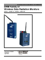
DRM Family of
Wireless Data Radiation Monitors
DRM-1, DRM-1D, DRM-2, DRM-2D
Document # 15-00044
Revision 5
April 2008
15-00044
Revision 5
April 2008
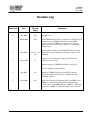
Revision Log
Revision #
Date
Revised
Pages
Comments
0
July 2004
N/A
Original issue.
1
March 2005
ALL
Added DRM-1D information, specifications, calibration, FCC
information about WRM2, instructions on using RMV
software (removed AMPView), and section for optional
display unit and corrected typographic errors (formatting).
Changed title.
2
May 2005
6,11-13, and
30
3
October 2006
15
Added outline drawings for the DRM-1/D and information
about the automatic background subtraction feature for the
DRM-1D
Added note about dipswitch settings for field use and
calibration, section 3.22
Better description of DRM-1D calibration, Section 9.1
Various editing throughout manual
4
July 2007
All
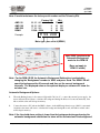
5
April 2008
ALL
Inclusion of DRM-2/2D, Power Saving Mode update,
Environmental & Solar Enclosure configurations, minor
editing through-out.
Added new features with firmware 071111 for DRM-1 and
DRM-2 for 4 threshold settings and selectable using the
‘ACK’ button on the DRM-1 display or DRM-2. Added new
screen shots of RMV for threshold settings and instructions
The publication, translation or reproduction, either party or wholly, of this document are not allowed without our written consent.
2
15-00044
Revision 5
April 2008
WRM-2 FCC COMPLIANCE
This device complies with Part 15 of the FCC rules. Operation is subject to
the following conditions: (1) this device may not cause harmful interference and (2) this
device must accept any interference received, including interference that may cause
undesired operation, FCC ID Number: ‘our9xstream’.
ANTENNA WARNING
This device has been tested with Reverse Polarity SMA and MMCX
connectors with the antennas that are supplied with the equipment. When integrated in the
OEM product, these fixed antennas require installation preventing end users from replacing
them with non-approved antennas. Any antennas not supplied by MGP Instruments must
be tested to comply with FCC Section 15.203 for unique antenna connectors and section
15 emissions.
FCC QUALIFICATIONS
Important:
The WRM2 radio modules have been certified by the FCC for integration
into OEM products without any further certifications (as per FCC section
2.1091). Changes not expressly approved by MGP Instruments could void
the user’s authority to operate this equipment.
Note:
The WRM2 System utilizes a proprietary communication (WRM) protocol
and specific firmware identification for each component and is configured
for optimal performance.
Operation of the WRM2 system in a configuration not consistent with MGPI
settings, or modifications to hardware and firmware may result in degraded
system performance and loss of warranty.
CAUTION:
Only the power supplies and batteries specified by MGPI should be used
with all DRM components. Non-approved power sources can result in
component damage or personal injury. Contact MGPI for additional
information!
The publication, translation or reproduction, either party or wholly, of this document are not allowed without our written consent.
3
15-00044
Revision 5
April 2008
Table of Contents
1.
DRM-1/2 and DRM 1D ...................................................................................................................6
1.1.
General Description...........................................................................................................................6
1.2
Applications for GM Tube (DRM-1, DRM-2) and CsI (DRM-1D) Detectors............................7
2.
DRM-1 Specifications ......................................................................................................................8
2.1
2.2
2.3
2.4
2.5
2.6
2.7
2.8
General DRM-1 (GM Tube) .............................................................................................................8
DRM-1D/2D Cesium Iodine (Tl) Specifications ..............................................................................9
DRM-2 Specifications .....................................................................................................................10
DRM Outline Drawings ..................................................................................................................12
DRM-1D Outline Drawings ............................................................................................................15
Over The Air Communications .......................................................................................................16
Response Times for the GM Tubes .................................................................................................16
DRM-1/2D Response Times for the CsI (Tl) Detector ...................................................................16
3.
Operating Instructions ..................................................................................................................17
3.1
3.2
3.3
3.4
Preparation for Use..........................................................................................................................17
Starting-Up ......................................................................................................................................17
Meter Connectors ............................................................................................................................18
Power Supply & Battery..................................................................................................................19
4.
General Functions ..........................................................................................................................20
4.1
4.2
4.3
4.4
Dipswitch Selector ..........................................................................................................................20
Dipswitch Positions .........................................................................................................................20
DRM-2 and Optional External Display & Alarm ...........................................................................26
Battery Replacement .......................................................................................................................27
5.
Communication ..............................................................................................................................28
5.1
5.2
Communication ...............................................................................................................................28
Protocol ...........................................................................................................................................28
6.
Communication Protocol ..............................................................................................................28
6.1
Set Meter Parameter Via the PC .....................................................................................................30
7.
Setting Meter Parameters Using the RMV Software .................................................................32
8.
Calibration Summary For The DRM-1/2 ....................................................................................35
8.1
Preface .............................................................................................................................................35
9.
Calibration Summary For The DRM-1D/2D ..............................................................................36
9.1
Preface .............................................................................................................................................36
The publication, translation or reproduction, either party or wholly, of this document are not allowed without our written consent.
4
15-00044
Revision 5
April 2008
10.
Calibration Procedure for the DRM-1D/2D ................................................................................37
10.1
10.2
10.3
10.4
10.5
10.6
10.7
10.8
10.9
Preface .............................................................................................................................................37
Operating Instructions .....................................................................................................................37
Template and Parameters ................................................................................................................37
Starting Up the Calibration and Linearity Process ..........................................................................39
Calibration .......................................................................................................................................40
Linearity ..........................................................................................................................................42
Save, Load and Print Calibration and Linearity Certificate ............................................................44
DRM-1/2 cps To Mr/H Conversion Table ......................................................................................45
DRM-1D cps To Mr/H Conversion Table ....................................................................................465
11.
Upgrading the DRM Firmware ....................................................................................................47
12.
DRM - List Of Electronic Schematics ..........................................................................................51
13.
DRM - Environmental Enclosure Configuration .......................................................................55
14.
DRM Solar Configuration ............................................................................................................57
The publication, translation or reproduction, either party or wholly, of this document are not allowed without our written consent.
5
15-00044
Revision 5
April 2008
1. DRM-1/2 and DRM-1D
1.1.
General Description
The Data Radiation Monitor - DRM-1/2, is an auto switching two GM-tube based dose rate meter and the DRM1D is a sensitive CsI (Tl) scintillated coupled to a PMT. The DRM-1/2 are dose rate meters for detection, using
state-of-the-art microprocessor-based technology and combined with telemetry using the WRM2 900 MHz or 2.4
GHZ FHSS radio. The DRM is designed for highly stable and accurate dose rate measurements from gamma
radiation. The DRM-1/2 (GM) measuring range is from 0.05 mR/h up to 1000 R/h and the DRM-1D’s measuring
range is from 0.001 mR/h up to 10 mR/h.
The DRM is a lightweight and compact instrument with sophisticated software offering special features and
optimal performance for telemetry data. The wide dynamic range is obtained by the DRM-1’s two GM-Tubes
with automatic range switching and an automatic dead time correction, according to the preset calibration. The
DRM-1D’s sensitive range is obtained by CsI(Tl) scintillator (30*30mm) coupled to PMT and an automatic dead
time correction and back ground subtraction, according to the preset calibration. A special averaging function
smoothes the data reading and maintains fast response time, while keeping the standard deviation at a minimum
for both DRM-1/2 and DRM-1/2D
Software is used to configure (RMV) and calibrate (RMC) the DRM family of detectors.
An automatic self-diagnostic procedure continuously checks both electronics and detectors and reports any case
of detector failure.
The DRM may be used in the following ways:
•
by connecting the meter to a PC
•
by connecting the meter to a DDC-16/AM-16 Area Monitor (wired)
•
by using the internal WRM2 FHSS radio to transmit data
•
by connecting the meter to an external WRM transmitter (wireless)
•
by using an internal or externally connected network adapter
The meter includes four boards: HV board, CPU board, WRM2 radio and the board for the dual GM-Tube
detectors or a cesium iodine detector. A built-in RS-232 is the connection used for calibration and configuration.
A custom connector is needed when using the WRM external transmitter. The WRM2 FHSS radio is already
included in the DRM-1/2 package and a base station (MGPI P/N: WR2-9001) is needed for reception of
telemetry data. A second DB-9 female connector is available for an optional alarm and display unit for the
DRM-1/1D.
The publication, translation or reproduction, either party or wholly, of this document are not allowed without our written consent.
6
15-00044
Revision 5
April 2008
1.2 Applications for GM-Tube (DRM-1, DRM-2) and CsI (DRM1D) Detectors
Perimeter & Boundary Surveillance
Vehicle Access Points
Turnstile entries
Collection of Survey Data for Real-time Mapping & Surveillance Software
General Area Monitoring
Hospital Emergency Room Entrances and CBRNE storage areas
Response vehicles
Event Monitoring
The publication, translation or reproduction, either party or wholly, of this document are not allowed without our written consent.
7
15-00044
Revision 5
April 2008
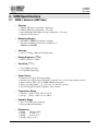
2. DRM Specifications
2.1 DRM-1 General (GM Tube)
•
Detector
GM tube ZP-1301 (or equivalent) - high range
GM tube ZP-1201 (or equivalent) - low range
Optional GM tube ZP-1300 non-energy compensated – low range
Optional CsI (Tl) detector
• Measuring Ranges :
0.05 mR/h to 1000 R/h (0.5 µSv/h to 10 Sv/h)
Automatic switching between the two GM tubes at
600mR/h and 800mR/h
• Accuracy
±10 % of reading, within the measuring range
• Energy Response (137Cs)
±20 % at 70 keV to 2 MeV
• Sensitivity (137Cs):
17 cps/mR/h (low range)
0.3 cps/mR/h (high range)
• Power Source
External power supply and battery backup
External power supply: Input 120-250 Vac, Output 6 Vdc to 15 Vdc with locking connector
Battery back-up: Three (3) 1.2v NiMH 2100mA rechargeable
Battery operating lifetime: Up to 12 hours of continuous operation
Power Saving Mode On/Off using Meter View Software
• Temperature Range
Operation: -10°C to +50°C (15°F to 122°F)
Storage: -20°C to + 60°C (-5°F to 140°F)
• Humidity Range
10% to 95% RH (non condensing)
Enclosure MaterialAluminum
• Dimensions
108 mm (4.25”)
Width:
Length:
178 mm (7”)
Height:
64 mm (2.5”)
Weight:: 907 gr. (2 lbs)
The publication, translation or reproduction, either party or wholly, of this document are not allowed without our written consent.
8
15-00044
Revision 5
April 2008
• Optional Accessories
Remote Display Unit (external visual & audible alarm)
Magnet attachments
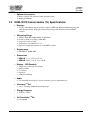
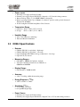
2.2 DRM-1D/2D Cesium Iodine (TL) Specifications
• Detector:
CsI (Tl) (30 x 30 mm) crystal optically coupled to PMT with 0.5 mm aluminum housing and
solid mu metal shield. With optional automatic background subtraction using the RMV
software.
•
Measuring Range
1uR/h to 9999 uR/h (0.001 mR/h to 9.999 mR/h)
Overflow Alarm for reading > 9999 uR/h
Overload for field > 1 R/h
Sensitivity: 6.8 cps/uR/h for 137-Cs
Optional : background subtraction via the RMV software
• Display range
0.01 mR/h to 10,000 mR/h
•
Dimensions
DRM-1D: 7" L x 3.5" D x 4.25" W
DRM-2D: 10.25” L x 4.28” D x 4.88 W
• Display – LCD Readout:
4 digits for accurate and easy display
Detector failure
Low battery
Overflow
4 Threshold Settings
• Audio:
Two internally mounted piezo-electric elements (used for alarm functions)
•
137
Accuracy (
Cs)
±10 % of reading, within the measuring range
•
Energy Response
45 KeV to 2 MeV
•
CsI Sensitivity (137Cs):
6.8 cps/µR/h
The publication, translation or reproduction, either party or wholly, of this document are not allowed without our written consent.
9
15-00044
Revision 5
April 2008
• Power source
External power supply and battery backup
External power supply: Input 120-250 Vac, Output 9 to 15 Vdc with locking connector
Battery back-up: Three (3) 1.2v NiMH 2100mA rechargeable
Battery operating lifetime: Up to 8 hours of continuous operation (with optional Alarm and
Display Unit: 4 hours)
Power Saving Mode On/Off using Meter View Software
• Temperature Range
Operation: -10°C to +50°C (15°F to 122°F)
Storage: -20°C to + 60°C (-5°F to 140°F)
• Humidity Range
10% to 95% RH (non condensing)
Enclosure Material Aluminum
2.3 DRM-2 Specifications
• Detector
GM tube ZP-1301 (or equivalent) - high range
GM tube ZP-1201 (or equivalent) - low range
Optional GM tube ZP-1300 non-energy compensated – low range
Optional CsI (Tl) detector
• Measuring Ranges :
0.05 mR/h to 1000 R/h (0.5 µSv/h to 10 Sv/h)
Automatic switching between the two GM tubes at
600mR/h and 800mR/h
• Display Range:
0.01 mrem/hr to 10,000 mrem/hr
• Accuracy
±10 % of reading, within the measuring range
• Energy Response (137Cs)
±20 % at 70 keV to 2 MeV
• Sensitivity (137Cs):
17 cps/mR/h (low range)
0.3 cps/mR/h (high range)
• Power Source
External power supply and battery backup
External power supply: Input 120-250 Vac, Output 6 Vdc to 15 Vdc with locking connector
The publication, translation or reproduction, either party or wholly, of this document are not allowed without our written consent.
10
15-00044
Revision 5
April 2008
Battery back-up: Three (3) 1.2v NiMH 2100mA rechargeable
Battery operating lifetime: Up to 12 hours of continuous operation
Power Saving Mode On/Off using Meter View Software
• Display – LCD Readout:
4 digits for accurate and easy display
Detector failure
Low battery
Overflow
4 Threshold Settings
• Audio:
Two internally mounted piezo-electric elements (used for alarm functions)
• Measurement Units:
mrem/hr
• Controls:
Alarm Acknowledgment push-button
DIP Switches for functionality
• Temperature Range
Operation: -10°C to +50°C (15°F to 122°F)
Storage: -20°C to + 60°C (-5°F to 140°F)
• Humidity Range
10% to 95% RH (non condensing)
Enclosure MaterialAluminum
• Dimensions
10.25” L x 4.28” D x 4.88 W
The publication, translation or reproduction, either party or wholly, of this document are not allowed without our written consent.
11
15-00044
Revision 5
April 2008
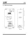
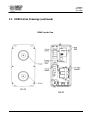
2.4 DRM Outline Drawings
The publication, translation or reproduction, either party or wholly, of this document are not allowed without our written consent.
12
15-00044
Revision 5
April 2008
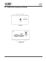
2.4 DRM Outline Drawings (continued)
The publication, translation or reproduction, either party or wholly, of this document are not allowed without our written consent.
13
15-00044
Revision 5
April 2008
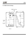
2.4 DRM Outline Drawings (continued)
DRM-1 Inside View
The publication, translation or reproduction, either party or wholly, of this document are not allowed without our written consent.
14
15-00044
Revision 5
April 2008
2.5 DRM-1D Outline Drawings
DRM-1D Inside View
The publication, translation or reproduction, either party or wholly, of this document are not allowed without our written consent.
15
15-00044
Revision 5
April 2008
2.6
Over the Air Communications
900 MHz or 2.4 GHz FHSS (Frequency Hopping Spread Spectrum) Radios with External Antenna (WRM2
system) – Base receiver required for use with WRM2 or WRM91, EXT-2000 External Transmitters and WRMPlus receiver.
2.7
Response Times for the GM Tubes
Table 1
Response Time for Small Changes
Radiation Field
Response
Range
Time
[mR/h]
[sec.]
< 0.5
45
0.5 - 1.5
30
1.5 - 2.5
20
2.5 - 6
10
6 - 12
6
12 - 24
4
20 - 60
3
60 - 800
2
0.6 - 1.2 R/h
5
1.2 - 2 R/h
4
2 - 3 R/h
3
3 - 10 R/h
2–3
> 10 R/h
≤2
Table 2
Fast Response Time
Radiation field
Response
[mR/h] from
Time
to/above
[sec.]
0.05
1.0
≤2
0.5
3.0
≤2
1.5
5.0
≤2
2.5
12
≤2
6
20
≤2
12
40
≤2
20
60
≤2
1 R/h
2 R/h
≤2
2 R/h
2.6 R/h ≤ 2
If the radiation field measured by the meter increases significantly, the response time will be ≤ 2 sec. as seen in
Table 2. In other cases the response time is according to Table 1.
For example:
• For a radiation field increase from 2.5 mR/h to 12 mR/h, the response time will be ≤ 2 sec.
• For radiation field fluctuations between 2.5 mR/h and 6 mR/h, the response time will be 10 sec.
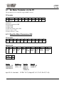
2.8
DRM-1/2D Response Times for the CsI (TL) Detector
The instrument’s response time is less then 2 seconds once the radiation intensity at the reference point increases
or decreases by a factor of 10. e.g 0.001 to 0.01 mR/h (1µR/h to 10µR/h).
The publication, translation or reproduction, either party or wholly, of this document are not allowed without our written consent.
16
15-00044
Revision 5
April 2008
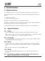
3. Operating Instructions
3.1 Preparation for Use
Remove the instrument from the shipping container and check for any physical damage. In the case of damage,
report it to the carrier and contact MGP Instruments.
Caution: Do not attempt to install or operate damaged equipment since safety and
performance may be affected.
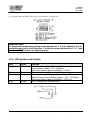
3.2 Starting-up
3.2.1
Connect the antenna to the WRM2 PRSMA connector located on the top of the enclosure. The
antenna is only needed when transmitting data over-the- air.
3.2.2
Switch dipswitch 3, for data output from the WRM2 radio, to the ON position or dipswitch 5 &
6 to the ON position when programming the internal WRM2 radio See “Wireless Remote
Monitoring Operating Manual”, 15-00043 for configuring the WRM2 radio.
Note: Ensure dipswitches 1,2,3,7 and 8 are in the ON position when deploying
the unit for field use. Dipswitch 4 must be in the OFF position at on times
for field use and calibration.
3.2.3
Switch dipswitch 7&8 to the ON position to engage the battery backup
3.2.4
Connect the external power supply to the locking miniature power supply connector
3.2.5
Connect external WRM transmitter if used and ensure that the baud rate for the DRM and the
WRM External Transmitter are set to 300 bps. The interval level for the DRM needs to be set to
ZERO (0), using RMV, so that the WRM transmitter can request the data from the device.
Note: By engaging the battery or the external power supply, the meter will start
operating. The unit is not supplied with an On-Off switch.
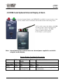
3.2.6
NOTE: (Firmware >= 071111 (MARCH 2008) and board updates) By pressing the ‘ACK
‘button once on the DRM-1 external display or the DRM-2 will show the current threshold rate
setting, thr.0 then the rate setting i.e., 300. By pressing the ACK button a second time and so
forth will show user preset threshold settings that were configured using the RMV software.
See section 4.2.10 for RMV software Dose Rate Threshold settings. See section 4.2.10 for more
information on setup and usage
ACK
thr.0 = selected ACK
thr.1 ACK
thr.2 ACK
thr.3 ACK
thr.4
The publication, translation or reproduction, either party or wholly, of this document are not allowed without our written consent.
17
15-00044
Revision 5
April 2008
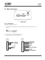
3.3 Meter Connectors
3.3.1 Connectors:
The DRM-1 contains three connectors:
1. 2.5 mm External power supply connector (type L712RA supplied by Switch craft, center post is
positive)
6 to 15v DC
(+)
Ground (-)
2. D-type 9 pin female for RS232 communication port
3. D-type 9 pin male for remote display & alarm
3
2
1
5
7
2
3
4
9
Ground
/common
Rx
Tx
5v
1
2
3
4
5
6
7
8
9
Display data
Display clk
Ready
Alarm
5v
Ground /common
Ext DC
Battery backup
The publication, translation or reproduction, either party or wholly, of this document are not allowed without our written consent.
18
15-00044
Revision 5
April 2008
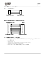
3.3.2 External Connectors:
Meter to PC RS232 Cable
2
3
5
D-type 9 pin female
3
2
5
D-type 9 pin male
Meter to External Display & Alarm Unit (lengh 25')
Display & Alarm Unit
Meter
1
2
3
4
5
6
7
8
9
D-type 9 pin female
3.4
1
2
3
4
5
6
7
8
9
D-type 9 pin female
Power Supply & Battery
• External power supply type CINCON 418-TR1507-12 (15v) with locking plug (type 761K Switchcraft
- center positive)
• Input 120-250 VAC
• Output 15 VDC 1.6A
• The meter can be operated using DC power from 5 volt to 16volt (0.7A)
• The meter is protected in case of reverse polarity
• Battery backup: 3 units of NiMH GP2100 type AA 1.2V, 2100mA
The publication, translation or reproduction, either party or wholly, of this document are not allowed without our written consent.
19
15-00044
Revision 5
April 2008
4. General Functions
4.1 Dipswitch Selector
To set the dipswitch, unscrew two screws located at the meter front panel and remove the dipswitch cover.
The dipswitch (8 switches) is located on the meter’s front panel. Using these dipswitches you can setup two
functions:
a) Communication mode, and;
b) Connect-disconnect the backup batteries.
Dipswitches position: For the ON position, press the dipswitch downward.
The DRM has one UART (Universal Asynchrony Receive Transmit Port) and one communication RS232 port;
the dipswitch position enables a selection of the communication mode
To set the dipswitch, unscrew two screws located at the meter front panel and remove the dipswitch cover.
4.2
Dipswitch Positions
4.2.1 1&2 On
•
Connects the DRM UART to the RS232 communication port via the D-type 9 pin female connector
•
Enables connection of the meter to PC for meter parameter setting, calibration or download the meter reading
directly to PC, (Using RMV software for configuration and RMC for calibration).
4.2.2 3 On & 4 Off
•
Connects the DRM UART to the internal wireless transmitter to send data reading via WRM2. Switch 3 is
for transmitting and Switch 4 is for receiving data.
4.2.3 5&6 On
• Connects the internal wireless transmitter to the RS232 communication port via the D-type 9 pin female
connector. See “Wireless Remote Monitoring 2 Operating manual, 15-00043” for configuring the WRM2
radio.
• Enables the setting of internal wireless transmitter WRM2 parameters.
4.2.4 7&8 On
• Connects the internal three NiMHd rechargeable batteries for back-up power if the external power is
disconnected
Note: If the external power supply is connected, the battery will be charged even
though the dip switches 7&8 are in the OFF position.
The publication, translation or reproduction, either party or wholly, of this document are not allowed without our written consent.
20
15-00044
Revision 5
April 2008
• Set switch 7&8 to the OFF position only in case the meter is being stored.
Important Note:
For operational/configuration settings ensure dipswitches 1, 2, and 3 (dipswitch 3 is for
transmitting data) are in the ON position. For field use ensure dip switches1, 2, 3, 7 and
8 are turned ON (7 and8 are for battery backup).
4.2.5 LED position and function
LED
Ext. power
Color
Red
Tx.
Battery
Green
Yellow
Rate
Yellow
Function
External power supply > 7.5v – led on
External power supply < 7.5v – led blinks
No external power supply & no Battery – LED off
For each transmission sent, the led blinks
Battery connected & Battery voltage > 7.5v – LED is on
Battery disconnected or Battery voltage < 7.5v – LED blinks
No external power supply & no Battery – LED is off
Blinks according the radiation trend
The publication, translation or reproduction, either party or wholly, of this document are not allowed without our written consent.
21
15-00044
Revision 5
April 2008
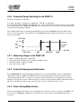
4.2.6 Automatic Range Switching for the DRM-1/2:
The detector includes two GM Tubes:
Low range - ZP-1201 (or equivalent), and high range - ZP-1301 (or equivalent).
In a field of 0.01 mR/h to 800 mR/h both GM tubes are connected and the field is measured by the low range GM
tube. If the radiation field is higher than 800 mR/h, the low range detector is disconnected, and the radiation field
is measured by the high range GM tube.
The switching between the low and high range GM-Tube is performed at 800 mR/h when the radiation field
increases (low range detector is disconnected), and at 600 mR/h when the radiation field decreases (low range
detector is connected).
GM Tube
ZP 1301
High
ZP 1201
Low
Overflow
alarm
Field
0.01 mR/h
600
mR/h
800 mR/h
1000
R/h
4.2.7 Measuring Range for the DRM-1/2D
•
•
•
•
mR/h to 10 mR/h (0.01 µSv/h to 100 µSv/h)
Automatic background subtraction is available via RMV software
Overflow Alarm for reading > 10 mR/h
Overload for field > 1 R/h
4.2.8 Automatic Background Subtraction
For the DRM-1/2D, the Automatic Background Subtraction is set (using the RMV software) by changing the
‘Background’ number to ‘9999’. The DRM-1/2D will count the background for 60 seconds and then set the
current background internally. To ensure a new update for the backgrounds, turn off dipswitches 7 and 8 and
unplug the AC adapter from power. When the device is powered on, the background will automatically update in
60 seconds. The displayed value on the optional display or software will show the net dose rate.
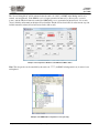
4.2.9 Power Saving Mode Feature
The Power Saving Mode will reduce power consumption in case the AC power is not present. The WRM2 radio
must be setup for Pin Sleep configuration, for this function to work properly. Contact MGP Instruments for
assistance.
The publication, translation or reproduction, either party or wholly, of this document are not allowed without our written consent.
22
15-00044
Revision 5
April 2008
The ‘Power Saving Mode’ will be activated after the send code ‘8888’ (via RMV in the Background icon) is
entered, sent and updated. If the DRM is set for a longer transmission interval (i.e. 60 seconds to conserve
power), and the Threshold alarm is reached, the DRM will be set to a transmission interval level of 4 seconds
(factory default) and transmit at the interval level until the Threshold Level rate falls below the current set point
and the transmission interval level will revert back to 60 seconds.
Example of the Setup Device Window for the DRM in the RMV Software
Note: The sleep mode can be cancelled by the send code ‘7777’ (via RMV in background icon) is entered, sent
and updated.
Example of the WRM2 Radio Configuration Screen (pin sleep)
The publication, translation or reproduction, either party or wholly, of this document are not allowed without our written consent.
23
15-00044
Revision 5
April 2008
The Interval time level is based on how long a unit can run without AC power, 99 seconds is the maximum
transmission time interval.
To check if the DRM is in Power Saving Mode press on the ‘GET BUTTON’ in the “Setup Device” window in
the RMV software and the background window will be display ‘8888’ to signify that the DRM is in the Power
Saving Mode.
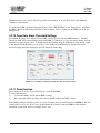
4.2.10 Dose Rate Alarm Threshold Settings
Dose threshold settings are configured via the RMV software (Version 4.01 and DRM firmware ). The Def.
Threshold (thr.0) is the current default setting in the DRM, i.e. Threshold (1) one is the current default dose rate
threshold (see figure below), thr.0. To change the threshold setting using the ACK button on the display, toggle
to the desired Threshold number, i.e. thr.3, let go of the ACK button and the display will show the stored
threshold setting and will be defaulted to this rate threshold alarm setting.
Example of the Setup Device Window for with the Dose Rate Threshold Settings
4.2.11 Dose Function
Dose reading can be read as a part of the data record sent by the DRM.
To enable this function:
1)
Connect the DRM to the PC and run RMV software
2)
Move dipswitch 1&2 to the ON position, and set DOSE enable in the RMV software
If the DOSE reading is disabled, in place of a real dose reading, the record will be shown as 888888.8. The Dose
reading will be reset to zero in two cases: Disable\Enable Dose function, turn the DRM On. Each time the
instrument is turned ON; the Dose reading is reset to zero.
The publication, translation or reproduction, either party or wholly, of this document are not allowed without our written consent.
24
15-00044
Revision 5
April 2008
4.2.12 WRM91 or WRM EXT 2000 Transmitter (optional)
WRM91 external radio transmitter can be connected to the DRM following these instructions:
1)
Connect the DRM to the PC and run RMV software.
2)
Set time interval to "0", and set baud rate to 300.
3)
Connect the WRM adapter to the DRM's Communication connector.
4)
Connect the WRM91’s RJ-22 connector to the WRM Adapter
5)
The DRM will transmit the data to the WRM91/Plus receiver.
Note: The WRM EXT 2000 external transmitter can be connected to the DRM in the
same manner as above, however, ensure that the Baud Rate is set to 300. Refer
to the EXT-000 Operating Manual, 15-00037, for configuration of the Baud Rate
setting.
The publication, translation or reproduction, either party or wholly, of this document are not allowed without our written consent.
25
15-00044
Revision 5
April 2008
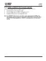
4.3 DRM-2 and Optional External Display & Alarm
An optional external display ( part # RTM-9135) is available for remote locations of the
read-out, audiable and/or visual alarms with and with an alarm acknowledge button.
A 25 foot cable connects the display to the DRM
via a D-type 9 pin connector and supplies the
power to the remote display. The DB-9
connectors must be fasten securely
for the display to operate properly.
Note: Internal battery life is reduced when no external power supplied is used while
using the remote display.
Remote Display Functionality Description
Status
Failure
Red Lamp
Green Lamp
Buzzer
Display
BLINK
OFF
BLINK
FAiL
No alarm &
ready
OFF
ON
OFF
Dose rate
reading [mR/h]
Failure
Over threshold alarm
BLINK
OFF
BLINK
FAiL
ON
ON
ON
Thr and Dose rate reading [mR/h]
simultaneous
The publication, translation or reproduction, either party or wholly, of this document are not allowed without our written consent.
26
15-00044
Revision 5
April 2008
4.3.1 DRM-2 and Optional External Display and Alarm Unit
A 7 segment 4 digit display unit displaying in the following formats:
Meter display format:
Measuring reading 0.000 to 9.999 mR/h for the DRM-1D
Measuring reading for the DRM-1:
1.
2.
3.
4.
5.
6.
0.001 to 9.99
10.0 to 99.9
100 to 999
1.0E to 9.99E
10.0E to 99.9E
100E to 999E
For numbers 1 -3 the units will be mR/h
For numbers 4 -6 (with E) the units will be R/h
OFLO
ALr.
Err1
Err2
in case of overload, reading > 10mR/h
and measuring reading blink simultaneity in case of meter reading is over the setting threshold alarm
in case of detector not connected.
In case of detector malfunction.
4.4
Battery Replacement
The battery holder is located inside of the DRM meter.
1)
2)
3)
4)
Disconnect the external power supply and switch dipswitch 7 & 8 to the OFF position
Unscrew the six screws located at the back meter panel.
Unscrew the two screws located at omega clip on the battery pack
Replace a new set of three 1.2v NiMH 2100 batteries
DO NOT USE ALKALINE BATTERIES AS REPLACEMENTS FOR THE NIMH BATTERIES
5)
6)
7)
8)
Screw back on the omega clip on the battery pack
Screw back the six screws located at the back meter panel.
Connect an external power supply.
The battery backup will be charged and ready for use after 16 hours
The publication, translation or reproduction, either party or wholly, of this document are not allowed without our written consent.
27
15-00044
Revision 5
April 2008
5. Communication
5.1 Communication
The communication between the DRM and PC can be performed in 3 ways:
1)
Wireless Radio WRM2 located inside the meter.
2)
Direct RS232 via the meter communication port (D-type 9 pin female connector using a Null
Modem Adaptor).
3)
WRM External Transmitter can be connected to the D-type 9 pin female connector via the AMP
to WRM adapter.
5.2 Protocol
Communication parameters:
•
•
•
•
•
•
•
•
Baud rate:
Parity:
Hardware handshaking:
Software handshaking:
Stop bit:
Prefix:
Suffix:
Data format:
can be selected between 300, 4800, 9600 and 19200 is the default.
None
None
None
1
LF
CR
8 data bits
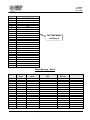
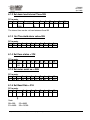
6. Communication Protocol
Description: DRM data to PC via radio or RS232
Byte 1 LF
Byte 2 to byte 7 Id meter number for communication set via Meter View software
Byte 8 status = 0x30=okay, 0x31=over load, 0x32=over threshold, 0x33=no external power, 0x34=low backup
battery, 0x38=detector fault.
Byte 9 Status = multiple status messages – See information below.
Byte 10 to byte 16 Dose Reading (x.xxxxx) or 8.88888 in case the Dose is disabled
Byte 17 = 0x30
Byte 18 to byte 22 rate reading X.YZW * 10 T
Byte 23 = 0x30
Byte 24 to byte 25 check sum
Byte 26 CR
The publication, translation or reproduction, either party or wholly, of this document are not allowed without our written consent.
28
15-00044
Revision 5
April 2008
Byte
1
2
3
4
5
6
7
8
9
10
11
12
13
14
15
16
17
18
19
20
21
22
23
24
25
26
Description
LF
N5
N4
N3
N2
N1
N0
Status
Status
D5
D4
D3
D2
D1
D0
D-1
30H
X
Y
Z
T
W
Status 3 lsb
CS msb
CS lsb
CR
See Table below
for Status 9
Status Message - Byte 9
Overflow
Threshold
Alarm
Loss of external
power
Low Battery or battery
OFF
Error with
Detector
1
1
1
1
1
1
1
1
1
1
1
1
1
1
1
1
1
1
1
1
1
1
1
1
1
1
1
1
Status Code
30H
31H
32H
33H
34H
35H
36H
37H
38H
39H
41H
42H
43H
44H
45H
46H
The publication, translation or reproduction, either party or wholly, of this document are not allowed without our written consent.
29
15-00044
Revision 5
April 2008
6.1 Set Meter Parameter via the PC
The parameters are set via the PC using the RMV software.
PC to meter
0
LF
1
Status
2
D5
3
D4
4
D3
5
D2
6
D1
7
D0
8
0F
9
0F
8
0F
9
0F
10
CR
Status byte:
Read meter parameters=30H
Set Baud=31H
Set Time=34H
Set Threshold alarm value.=35H
Set Dose status = 37H
Set meter serial no. = 38H
6.1.1 Read the Meter Parameters=30H
PC to meter
0
1
2
LF
30
20
3
20
Meter to PC
0
1
2
LF 30
Meter
type
3
Meter
unit
4
20
5
20
4-9
Meter
#
6
20
10-14
Thr.
value
7
20
15
Meter
baud
16-19
Down
load
time
10
CR
20
Dose
En/Dis
21-26
Firmware
version
27-28
29
36h,37h CR
Byte 2:
AMP50 = 30
AMP100=31
AMP200=32
Byte 3:
mR/h = 30
uSv/h = 31
byte 10-14 : threshold
byte 15:
300=30
4800=31
9600=32
19200=33
byte 20
disable =30
enable=31
X.YZW * 10 T (X=byte10, Y=11, Z=12, W=13, T=14)
The publication, translation or reproduction, either party or wholly, of this document are not allowed without our written consent.
30
15-00044
Revision 5
April 2008
6.1.2 Set down load interval Time=34H
PC to meter
0
1
2
LF 34 Sec*
1000
3
Sec*100
4
Sec*
10
5
sec
6
20
7
20
8
0F
9
0F
10
CR
The interval time can be set from between 0 and 99
6.1.3 Set Threshold alarm value=35H
PC to meter
0
1
2
LF 35 X
3
Y
4
Z
5
W
6
T
6
20
7
0F
8
0F
9
CR
7
20
8
0F
9
0F
10
CR
6
D1
7
D0
8
0F
9
0F
10
CR
6
20
7
20
8
0F
9
0F
10
CR
6.1.4 Set Dose status = 37H
PC to meter
0
1
2
LF 37 D-30
E-31
3
2
0
4
20
5
20
6
20
6.1.5 Set meter serial no. = 38H
PC to meter
0
1
2
LF 38 D5
3
D4
4
D3
5
D2
6.1.6 Set Baud Rate = 31H
PC to meter
0
1
2
LF 31 code
Code:
30h=300
31h=4800
3
2
0
4
20
5
20
32h=9600
33h=19,200
The publication, translation or reproduction, either party or wholly, of this document are not allowed without our written consent.
31
15-00044
Revision 5
April 2008
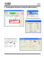
7. Setting Meter Parameters using the RMV Software
Set PC communication parameters
Select meter type:
AMP + DRM
Set & Display Meter Parameters
To set new parameter value, type the
required value on each window and then
click on the Send button for each
parameter.
i.e.: Interval
= 10 Threshold = 1000 Send
Send
The publication, translation or reproduction, either party or wholly, of this document are not allowed without our written consent.
32
15-00044
Revision 5
April 2008
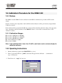
RMV Operating Instructions:
1)
Start the RMV software by CLICKING on the CALIBRATION button on the RMV software connect the
DRM to the P.C. via the RS232 connection with a null modem connector, ensure dipswitches 1 and 2 on in
the ON position.
2)
Set the correct Communication port
3)
Select meter type, AMP+DRM
4)
Verify that the communication between the meter and the PC is okay. If the communication is fail, change
the baud rate by clicking on the Setting, Communication port button, and select another baud rate. Then
click on Utility, Test to check again.
Failed communication
Communication OK
5)
Once the communication is okay, use the Setting, Setup AMP button to configure the meter's working
parameters.
6)
The Serial Number shown in the Setup Device screen refers to the ID number used in the communication
protocol and not the serial number of the instrument which is setup using the RMC (Rotem Meter
Calibration) or the AMP View software. All portable instruments telemetry ID will start with a ‘9’
followed by the unique identification number
Meter Code for Telemetry (Area Monitors/Portable Instruments 9xxxxx)
Instrument
TelePole
Ram Ion
AMP-50
AMP-100
AMP-200
DRM-1
DRM-1D
Type Code
0
1
2
3
4
5
6
The publication, translation or reproduction, either party or wholly, of this document are not allowed without our written consent.
33
15-00044
Revision 5
April 2008
Note: Correlation between the factory serial number and the Telemetry ID #
AMP- 50
AMP-100
AMP-200
DRM-1
Factory S.N.
09 02 801
9
50 02 001
9
77 02 501
9
11004 - 0008
9
ID #
22 801
32 001
42 501
54 008
9 54 008
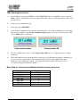
Example:
Meter type year serial # (DRM-1)
Input ‘9999’ to activate the
Automatic Background
mode for the DRM-1D
(Does not apply to
DRM-1/2 model)
Note: For the DRM-1D/2D, the Automatic Background Subtraction is activated by
changing the ‘Background’ number to ‘9999’ and press Send. The DRM-1/2D will
count the background for 60 seconds and then set the current background
internally. The displayed value on the optional display or software will show the
net dose rate.
Automatic Background Options:
1.
When the Backup battery is disconnected (dipswitch 7& 8 in off ) , connect the external power supply, the
meter will turn ON and enter to calculate the background during the 60 second count, automatically, after
60 second this value will be kept in memory
2.
Connect the meter to PC and run the RMV software, in the AMP setup function type ‘9999’ for automatic
calculation, the meter will enter to calculate the background during 60 second, after 60 second this value
will be kept in memory.
Note: If the threshold alarm setting is lower then the background when performing the
automatic background subtraction the alarm will be activated until the background
The publication, translation or reproduction, either party or wholly, of this document are not allowed without our written consent.
34
15-00044
Revision 5
April 2008
is stored and the display is showing the net rate.
3.
Connect the meter to PC (using the null modem adapter) and run the RMV software, in the Amp setup
function type desirable ‘9999’ the background value.
8. Calibration Summary for the DRM-1/2
8.1 Preface
8.1.1 Calibration Factors
To improve the linearity, the DRM-1 includes five calibration factors: The two lower factors are for the low
range GM tube, from 0.01 mR/h to 800 mR/h; and the other three are for the high range GM tube, from 600 mR/h
to 1000 R/h. Once the F factors have been set a linearity verification should be performed on all ranges.
The calibration factors will be set using the RMC software:
F1 - first calibration factor for low range.
F2 - second calibration factor for low range.
F3 - first calibration factor for high range.
F4 - second calibration factor for high range.
F5 - third calibration factor for high range.
•
•
•
•
F1 and F3 are used to compensate the GM tube sensitivity tolerances.
F1 for the low range (ZP1201) and F3 for the high range (ZP1301).
F2, F4 and F5 are used to compensate the dead time tolerances.
F2 for the low range (ZP1201) and F4, F5 for the high range (ZP1301).
8.1.2 Calibration Ranges
F1 must be set at 50 mR/h ± 20 mR/h
F2 must be set at 350 mR/h ± 50 mR/h
F3 must be set at 10 R/h ± 2 R/h
F4 must be set at 200 R/h ± 60 R/h
F5 must be set at 600 R/h ± 100 R/h
Measured (displayed) readings are calculated by one of the following two formulas, depending on the
intensity of the radiation field:
• Low range: N(mR/h) = [n*F1 + dead time correction {n*F2}]/17
• High range, up to 300 R/h: N(R/h) = [n*F3 + dead time correction {n*F4}]/300
• High range, over 400 R/h: N(R/h) = [n*F3 + dead time correction {n*F5}]/300
Where
n is the detector frequency obtained in the radiation field.
N is the updated measurement reading.
Between 300 R/h to 400 R/h, a weighed average of F2 and F3 is used as the dead time correction factor. The
calculation of the "averaged factor" and the corresponding measurement formula follow:
x = (last N(R/h) - 300)/100
The publication, translation or reproduction, either party or wholly, of this document are not allowed without our written consent.
35
15-00044
Revision 5
April 2008
Last N = previous measurement reading
F average = (1-x)* F4 + x* F5
N(R/h) = [n*F1 + dead time correction {n*F average}/300
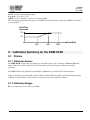
The following graph illustrates the ranges over which F2, F3 and F average are used as the DRM-1’s dead time
correction factor:
Dead Time
Correction
F3
F2
F
Field [R/h]
300
400
1000
9. Calibration Summary for the DRM-1D/2D
9.1 Preface
9.1.1 Calibration Factors
The DRM-1D/2D requires only one calibration point which requires only one change to Factor 1 (F1) in the
Meter Calibration software. Once the F1 factor has been set performed, linearity verification should be
performed.
The DRM-1D/2D can be calibrated via the RS232 communication port with a NULL modem adapter.
Switch to the ON position dipswitches 1&2 for RS232 and the calibration will be performed by using the Meter
Calibration software. Refer to section 10.1 for instructional use of the calibration software
9.1.2 Calibration Ranges
F1 is recommended to be set at 0.1 to 0.2 mR/h.
The publication, translation or reproduction, either party or wholly, of this document are not allowed without our written consent.
36
15-00044
Revision 5
April 2008
10. Calibration Procedure for the DRM-1/2D
10.1 Preface
The DRM-1/2 and the DRM-1D can be calibrated via the RS232 communication port with a NULL modem
adapter.
Switch to the ON position dipswitches 1&2 for RS232 and the calibration will be performed by using the Meter
Calibration software.
If the radiation field is greater than 10 mR/h, the software will automatically enable the setting of the appropriate
factor, depending on the field intensity for the DRM-1/2. Refer to section 10.1 for instructional use of the
calibration software.
10.1.1 Calibration Ranges
F1 in a field > 10 mR/h and < 100 mR/h.
F2 in a field > 100 mR/h and < 800 mR/h.
F3 in a field > 800 mR/h and < 50 R/h.
F4 a field > 50 R/h and < 350 R/h.
F5 in a field > 350 R/h
Note: If the radiation field is lower than 10 mR/h, each factor can be set manually by the
calibration software.
10.2 Operating Instructions
1.
Run the calibration program via the RMC.EXE file (or icon).
2.
Enter a Login name/calibrator (‘jsmith’) name that will appear in the calibration
(up to 12 characters).
documentation
3. Enter Password – “mgpi” in lower case.
The publication, translation or reproduction, either party or wholly, of this document are not allowed without our written consent.
37
15-00044
Revision 5
April 2008
4.
Click OK, the program enters the main window.
5.
The caption in the main window (linearity report) displays the previous template. In the displayed
template the operator executes the required operations to complete the calibration and linearity.
6.
To start the procedure, click File/New Report.
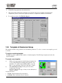
10.3 Template & Parameters Setup
The template includes setup parameters and instrument parameters. To select or create a new template, proceed
as follows.
To select an existing template
The RMC program is supplied with a number of default templates. Click File/ Open template and select the
required template.
To create a new template
a)
Fill the following parameters in the displayed template: Src
(source), Measuring Point including units, Distance, and
Attenuators. To select between mR/h and R/h, or cps and
Kcps, or cpm and Kcpm, click each of the unit’s columns.
b)
Select Parameters / Setup from the pull down menu.
Complete the following
Customer - Enter header (up to 4 lines) for the calibration &
linearity certificate.
Accepted accuracy:
• As Left - Enter maximum allowed deviation
• As Found - Enter maximum allowed deviation
The publication, translation or reproduction, either party or wholly, of this document are not allowed without our written consent.
38
15-00044
Revision 5
April 2008
•
•
•
•
•
Source 1 - Enter source type used in the calibration facility.
Source 2 - Enter source type used in the calibration facility.
Calibration due - Set the calibration interval.
Click OK to save data and quit.
Click Cancel to cancel data changes and quit.
Select Parameters / Template from the pull down menu.
In the Template Settings window perform the following:
Template name - Fill new template name
Instrument - Select instrument type/ name
Note: For the DRM select TelePole meter.
Units - Select units to be used in this template
New template - Save current template settings into a new file
Open template file - Select existing template without changing it
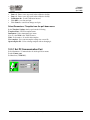
10.3.1 Set PC Communication Port
Select Parameters / Communication from the pull down menu.
Set the Comm. port.
Set Baud rate (19200 BPS).
The publication, translation or reproduction, either party or wholly, of this document are not allowed without our written consent.
39
15-00044
Revision 5
April 2008
10.4 Starting-up the Calibration & Linearity Process
1)
2)
3)
4)
5)
6)
Connect the DRM to the computer via the appropriate Comm. Port using a NULL Modem adaptor
(according to the selected port in the set up program).
Turn the meter on and ensure dipswitches 1 and two are in the ON position
Execute the RMC file.
Enter User name up to 12 characters i.e., jsmith.
Enter Password, type mgpi (in small letters).
To check and calibrate the instrument, first enter Linearity and check As Found. Then enter from the pull
down menu to Instrument/ Calibration. After calibration is performed, return to Linearity and check As
Left.
Note: If the computer / instrument communication failure or is disconnection, the
Communication Error Message is displayed in the computer’s display. Check the
communication cable, Comm. Port, or dip switch settings on the DRM. Also,
check the communications port of the PC.
The publication, translation or reproduction, either party or wholly, of this document are not allowed without our written consent.
40
15-00044
Revision 5
April 2008
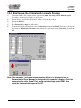
10.5 Calibration
Select Instrument/Calibrate… from the pull down menu. The calibration menu will be displayed.
(1) Instrument reading – Current dose rate reading
(2) Factor Num. - Factor number for the calibration. The listing in this screen depends on the amount of
calibration points available from the instrument. If the “Auto” radio button is selected the software will recognize
the filed value and allow for calibration of the pertinent point. If the calibrator wants to insert a factor into a
specific range, he or she simply selects the field.
(3) Factor Num. - Current active factor number. This window will display the current active factor number
and is especially useful in the Auto mode for reference purposes.
Note: The calibration factors are selected according to the detector's radiation field
location. Only the displayed factor can be changed.
(4) Old Factor: - Previous calibration factor as saved (stored) in the instrument memory.
(5) Enter Radiation Field: - Factor can be changed in two modes:
a.
b.
Insert the measured field. The computer will calculate the new factor dependant on the radiation field
and the old factor. The new factor value will be displayed on the New Factor box.
Using the ± boxes.
The publication, translation or reproduction, either party or wholly, of this document are not allowed without our written consent.
41
15-00044
Revision 5
April 2008
(6) New Factor: - The New Factor will be displayed and is a function of the actual current reading against the
Radiation field that was typed into the window. If the calculated factor value is lower than 0.6 or higher than
1.4, calibration will be not performed.
(7) Force 1 – Select in case the operator wants to force the calibration factor to 1.00. Use this when an
incorrect factor was stored.
(8) After the factor changing, press Update Factor. Ensure to obtain the status: Factor Accepted.
(9) Update Details - Press Update Details.
(10) Ensure to obtain Status: Details Accepted.
(11) End Calibration – Click to quit the calibration function and return to the main menu.
(12) Background sub (currently not in use).
10.6 Linearity
To enter the Linearity Report window press File → New Report. The Linearity Report window includes
As Found and As Left columns. Before calibration and linearity check, perform the proceeding steps in the
following order:
1) Check the linearity in As Found column.
2) If linearity fail is obtained the instrument is defective and cannot be calibrated (P/F –fail).
3) If linearity As Found is ok, calibrate the instrument.
4) Check the linearity in As Left column.
5) In order to check linearity and perform calibration to other instrument, select
File →New report on the pull down menu.
The publication, translation or reproduction, either party or wholly, of this document are not allowed without our written consent.
42
15-00044
Revision 5
April 2008
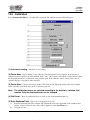
10.6.1 Linearity Report Window Description
Src – Type of source employed for calibration and linearity. The source type is defined in the set-up parameters.
Meas.Point - Radiation field where linearity tests are performed.
Unit - Measurement units.
Distance and Att. - Distance between detector and source and attenuator factor.
As Found - Instrument reading prior to calibration.
As Left - Instrument reading after calibration.
Err% - Reading deviation % between measuring point (calculated value) and meter reading.
P/F - Notifies that linearity checking is correct.
Serial Number - Instrument number, may be changed in Parameters / Instrument.
Accepted accuracy - Permitted deviation in % between the instrument reading and radiation. Defined in the
Parameters / Set up.
Sources [Src] - Source type by which calibration and linearity were performed. Defined in the set-up
parameters.
Customer Header- Customer: Enter header (up to 4 lines) for the calibration & linearity certificate.
Curr. Calibrator - Present calibrator's name and calibration date.
Prev. Calibrator - Former calibrator's name and calibration date.
Factors - Factors' value.
(1) Checking adequate connection between instrument and computer. If after the fifth time there is no
communication, an alarm message is displayed.
(2) 0.00 mR/h - Instrument reading is updated every second.
(3) Closed - After checking the first reading by pressing X on the tested point line, it is recommended to perform
File → Save as. From now on, the file is automatically updated and saved after checking of each tested point. As
long as the Closed text box is not marked, it is possible to make changes while entering and exiting the file. At
the end of the linearity check process, marking ✓in the Closed text box will make the file "read only". From now
on, when entering the saved file marked ✓ Closed, it will be impossible to perform any changes in the Linearity
Report window.
The publication, translation or reproduction, either party or wholly, of this document are not allowed without our written consent.
43
15-00044
Revision 5
April 2008
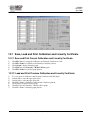
10.7 Save, Load and Print Calibration and Linearity Certificate
10.7.1 Save and Print Current Calibration and Linearity Certificate
1)
2)
3)
4)
5)
Click File / Save for saving the Calibration and Linearity Certificate in a file.
Click File / Print for Calibration and Linearity Certificate printout.
Click Graph to display Linearity graph.
Click Plot and select Linearity or Relative Error graph.
Click File / Print for Linearity graph printout.
10.7.2 Load and Print Previous Calibration and Linearity Certificate
1)
2)
3)
4)
5)
6)
7)
To load a previous Calibration and Linearity Certificate click File/ Open.
Double click to select the appropriate drive.
Double click to select the appropriate file.
Click File / Print for Calibration and Linearity Certificate printout.
Click Graph to display Linearity graph.
Click Plot and select Linearity or Relative Error graph.
Click File / Print for Linearity graph printout.
The publication, translation or reproduction, either party or wholly, of this document are not allowed without our written consent.
44
15-00044
Revision 5
April 2008
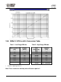
10.8 DRM-1/2 CPS to mR/h Conversion Table
Table 1 - Low Range GM tube
•
Input Frequency
[Hz]
Display
[mR/h]
17
170
2000
4000
5000
6000
6300
1.00
10.0
141
365
534
730
804*
Table 2 - High Range GM tube
Input
Frequency
[Hz]
300
3200
10.000
30.000
40.000
50.000
60.000
75.000
Display
[R/h]
1.00
10.7
39.2
183
323
525
839
O.F. (overflow)
Switches to high range detector
Note: These results are valid only when all factors equal to 1.
The publication, translation or reproduction, either party or wholly, of this document are not allowed without our written consent.
45
15-00044
Revision 5
April 2008
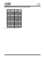
10.9 DRM-1D/2D CPS to mR/h Conversion Table
Input Frequency
[KHz]
1
2.8
4.9
8.75
11.9
14.6
16.9
19.1
21.1
22.7
24.4
25.8
28.5
30
Display
[mR/h]
0.147
0.397
0.795
1.590
2.385
3.180
3.975
4.770
5.565
6.360
7.155
7.950
9.540
OFLO
These results are valid only when F1 is equal to 1
The publication, translation or reproduction, either party or wholly, of this document are not allowed without our written consent.
46
15-00044
Revision 5
April 2008
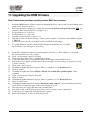
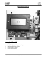
11. Upgrading the DRM firmware
Note: Follow these directions carefully (contact MGPI for assistance)
1.
2.
3.
4.
5.
6.
7.
8.
9.
10.
11.
12.
13.
14.
15.
16.
17.
18.
19.
20.
21.
22.
23.
24.
25.
26.
Install the DRM Firmware Updater software by unzipping the files to a known directory and clicking on the
‘Setup’ in the ‘Installer’ directory.
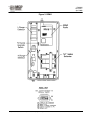
Disconnect the meter from the power supply and ensure that the battery back-up is also turned OFF; dip
switches 1 and 2 in the OFF position, see figure 2 or 3
Set dipswitch 1& 2 to on position
Set dipswitch 3 to 8 to off position
Open the back meter panel, see figure 2 or 3
Switch E1 located at mother board card to update position (upward). See Figure2 for the DRM-1 or Figure
3 DRM-1D
Connect the meter to the PC via the RS-232 cable and NULL modem adapter.
To start the Firmware Updater software double clicking the ‘Application.exe’ icon in the
known directory.(see next page for screen view)
Set the PC Communications Port and load the supplied *.hex file,, i.e. “drm1-4769.hex” located in the
known created directory for the software.
Select "send an answer " function 1 (Check)
Click on the Start (white arrow) to initialize the program.
Connect the meter to the power supply information should appear in the File Read screen.
If the menu does not appear, turn (disconnect) the power supply off, click on the stop (red point) icon and
go back to item 10
Click on the "send 1" button
Check that the right hand window displays “Enter to command > 1 **** Ready to receive
Click on "send 2"
Check that the right hand window displays “The file was verified and is good for update” Enter
command
Select "send an answer " function 2 (Update)
Click on "send 1"
Check that the right hand window displays “Enter to command > 2 **** Ready to Receive
Click on "send 2" wait…
Check that the right hand window displays “Firmware update complete” and verify that the information
in the window is exactly like figure 1 before removing the AC power
Disconnect the power supply and remove the serial/null cable.
Switch E1 located on the motherboard card 2143 to inverse "update" position (downward).
Connect the power supply and verify that the meter operates.
Ensure Dip Switches 1, 2, and 3 are in the ON position.
The publication, translation or reproduction, either party or wholly, of this document are not allowed without our written consent.
47
15-00044
Revision 5
April 2008
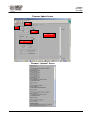
Firmware Update Screen
Stop
Start
Com
Dialog screen
New *.hex file
Firmware “Updated” Screen
The publication, translation or reproduction, either party or wholly, of this document are not allowed without our written consent.
48
15-00044
Revision 5
April 2008
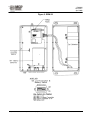
Figure 2. DRM-1
The publication, translation or reproduction, either party or wholly, of this document are not allowed without our written consent.
49
15-00044
Revision 5
April 2008
Figure 3. DRM-1D
The publication, translation or reproduction, either party or wholly, of this document are not allowed without our written consent.
50
15-00044
Revision 5
April 2008
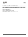
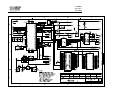
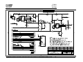
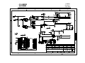
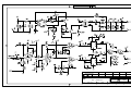
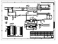
12. DRM - List of Electronic Schematics
Note: The following schematics are for information only and are not subject to revision
control.
DRW #12850-40-00 CPU - PC #2142
DRW #12850-40-00 Mother Board PC #2143
DRW #12852-40-00 DRM WR, GM Detector, PC #2003
DRW #12852-40-00 DRM WR, PMT HV PC #2173
DRW #12852-40-00 DRM WR, ALARM & DISPLAY PC #2175
The publication, translation or reproduction, either party or wholly, of this document are not allowed without our written consent.
51
15-00044
Revision 5
April 2008
OnOff2
17-05- 2004
DWG:
138404000
MODEL:
AnkryN
BenAmi E.
Eli V.
13840
FILE:
pcb2142
Zchut S.
P.C.
AnkryN
2142
SHEET:
1
OF:
1
15-00044
Revision 5
April 2008
SIGNATURE
VER.
1
2
0
REV.
0
2705 2003
Eli V.
Eti BA
Shlomo Z.
AnkryN
0502 2003
Eli V.
Eti BA
Shlomo Z.
AnkryN
DRM0405002
DRM
MOTHER BOARD
DWG:
138404100
The publication, translation or reproduction, either party or wholly, of this document are not allowed without our written consent.
MODEL:
53
13840
FILE:
pcb2143
P.C.
2143
SHEET:
1OF: 1
15-00044
Revision 5
April 2008
VER
15-00044
Revision 5
April 2008
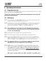
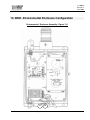
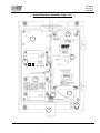
13. DRM - Environmental Enclosure Configuration
Environmental Enclosure Assembly: Figure 13-1
11
10
The publication, translation or reproduction, either party or wholly, of this document are not allowed without our written consent.
55
15-00044
Revision 5
April 2008
Environmental Enclosure Assembly (Figure 14-1)
1
2
3
4
5
6
7
8
9
10
11
Mounting Plate
Circuit Board
Power Supply
Telemetry Antenna
Antenna Cable
Strobe Light
DRM-1/D Monitor
Power Cable
Environmental Enclosure
Audible Buzzer
Acknowledge Pushbutton
The publication, translation or reproduction, either party or wholly, of this document are not allowed without our written consent.
56
15-00044
Revision 5
April 2008
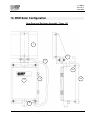
14. DRM Solar Configuration
Solar Panel and Enclosure Assembly: Figure 14-1
1
7
2
6
4
3
8
5
The publication, translation or reproduction, either party or wholly, of this document are not allowed without our written consent.
57
15-00044
Revision 5
April 2008
Internal Enclosure Assembly: Figure 14-2
9
1
8
2
3
4
7
6
5
The publication, translation or reproduction, either party or wholly, of this document are not allowed without our written consent.
58
15-00044
Revision 5
April 2008
Solar Panel & Enclosure Assembly (Figure 14-1)
1
2
3
4
5
6
7
8
Solar Panel element
Power Cable (Solar Panel)
Environmental Enclosure
Door Locking Mechanism
Telemetry Antenna
Bushings (4)
Mounting bracket for Solar Panel element
Mounting plate
Internal Enclosure Assembly (Figure 14-2)
1
2
3
4
5
6
7
8
9
Mounting plate
Interface Board
Sealed Lead Acid Battery
RPSMA to N-Type Antenna Cable
Telemetry Antenna
Power Cable Connector
DRM-1 Power Connector
DRM-1 Detector
RPSMA Antenna Connector
The publication, translation or reproduction, either party or wholly, of this document are not allowed without our written consent.
59
15-00044
Revision 5
April 2008
Interface Board: Figure 14-3
6
1
5
2
3
4
Interface Board (Figure 14-3)
1
2
3
4
5
6
LCD Display
Pushbutton – display Solar Power draw (voltage)
Pushbutton – display Battery Voltage
Emergency Battery (power) connector
Power – Charging - Connector
Main On-Off Power Switch
The publication, translation or reproduction, either party or wholly, of this document are not allowed without our written consent.
60
SIGNATURE
1
0
28-12-04
Wolaski E. BEN-AMI E.
ZECHUT S. ANKRI N.
DRM1/DRM1D
HV - SUPPLAY
DWG:
13845-40-00
MODEL:
13845
FILE:
pcb2173
P.C.
2173
SHEET:
1OF: 1
SIGNATURE
VER 3 REV 0
VER 2 REV 0
1
0
19-07-05
08-02-05
Wolaski E.
Wolaski E.
BEN-AMI E. ZECHUT S.
BEN-AMI E. ZECHUT S.
ANKRI N.
ANKRI N.
04-01-05
Wolaski E.
BEN-AMI E. ZECHUT S.
ANKRI N.
DRM0507003
DRM0502001
DRM1/DRM1D
Alarm Display
DWG:
13845-40-00
MODEL:
13845
FILE:
P.C.
2175
SHEET:
1 OF:
1