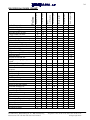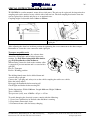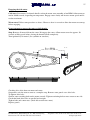
1
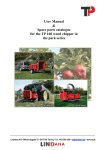
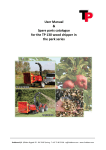
INSTRUCTION MANUAL & SPARE PARTS CATALOGUE FOR PARK SERIES TP 150 – 200 - 250 Congratulations on your new TP Wood Chipper. To make sure you gain the most out of the wood chipper it is advisable to read these instructions before using the machine. When ordering spare parts, please state the following: 1) Model and series number (see nameplate). 2) No. off, spare parts number and description (see spare parts catalogue). 3) Consignee name and address. 4) Method of transportation. _________________________________________________________________________ EU DECLARATION OF CONFORMITY Manufacturer: LINDDANA A/S, Ølholm Bygade 70, Ølholm, 7160 Tørring, Denmark declares that Wood chipper: TP 200 VHM (045/9695) Model Series number is in accordance with the EU DIRECTIVE of 14 June 1989 on the approximation of the laws of the Member States relating to machinery (89/392/EEC amended by 91/368/EEC, 93/44/EEC, 93/68/EEC and 2000/14/EC) with special regard to Annex 1 of the directive on essential safety and health requirements in connection with the design and manufacture of machines. Title: Director Name: Jan Knudsen 1. September 2001 Date Signature 2 CONTENTS EU DECLARATION OF CONFORMITY................................................................................................... 1 CONTENTS.................................................................................................................................................. 2 TECHNICAL DATA: ................................................................................................................................... 3 APPLICATION............................................................................................................................................. 3 CONNECTION/MOUNTING ...................................................................................................................... 4 OIL TYPES – TEMPERATURE AND VISCOSITY .................................................................................. 5 OPERATION ................................................................................................................................................ 5 KNIVES AND ANVILS ............................................................................................................................... 6 ANVIL REPLACEMENT ............................................................................................................................ 6 KNIFE REPLACEMENT............................................................................................................................. 7 WOOD CHIPPING....................................................................................................................................... 9 SAFETY HANDLE .................................................................................................................................... 10 SAFETY RULES ........................................................................................................................................ 11 PICTOGRAMS........................................................................................................................................... 12 NOISE LEVEL ........................................................................................................................................... 13 MAINTENANCE ....................................................................................................................................... 14 FAULT LOCATION TABLE..................................................................................................................... 15 ASSEMBLY AND REPAIR....................................................................................................................... 16 TERMS OF WARRANTY ......................................................................................................................... 16 MAINTENANCE SCHEDULE, TP 150-200-250 ..................................................................................... 17 SPECIAL INSTRUCTIONS FOR TP 200 DH........................................................................................... 18 SPECIAL INSTRUCTIONS FOR TP 150 PHM........................................................................................ 19 TECNICAL DATA FOR LDW 1003: ........................................................................................................ 21 ENGINE MAINTANANCE OPERATIONS ............................................................................................. 23 ENGINE DIAGNOSIS CHART. ................................................................................................................ 24 SPECIAL INSTRUCTIONS FOR TP 200 VHM ....................................................................................... 25 SPECIAL INSTRUCTIONS FOR TP 200 DHM ON TURNTABLE:....................................................... 25 SPECIAL INSTRUCTIONS FOR TP 250 DHM ....................................................................................... 26 HYDRAULICCHART, TP150 WITHOUT OVERLOAD PROTECTION............................................... 29 HYDRAULICCHART, TP150 WITH OVERLOAD PROTECTION ....................................................... 29 HYDRAULICCHART, TP 200 WITHOUT OVERLOAD PROTECTION.............................................. 30 HYDRAULICCHART, TP 200 WITH OVERLOAD PROTECTION ...................................................... 30 HYDRAULICCHART, TP 250 WITHOUT OVERLOAD PROTECTION.............................................. 31 HYDRAULICCHART, TP 250 WITH OVERLOAD PROTECTION ...................................................... 31 HYDRAULICCHART, TP 250 WITH CRANE ........................................................................................ 32 USER´S MANUAL HC 960CHIPPER CONTROL................................................................................... 33 INTRODUCTION....................................................................................................................................... 34 OPERATING MODES ............................................................................................................................... 34 PARAMETERS IN SEMI AUTOMATIC MODE..................................................................................... 35 PARAMETERS IN FULLY AUTOMATIC MODE.................................................................................. 36 PROGRAMMING THE PARAMETERS .................................................................................................. 37 HOURMETERS ......................................................................................................................................... 38 HOW TO CONFIGURE THE OUTPUT ................................................................................................... 38 GENERAL HINTS ..................................................................................................................................... 39 TECHNICAL DATA .................................................................................................................................. 39 Linddana A/S, Ølholm Bygade 70, DK-7160 Tørring, Instructions: TP 150-200-250 dated 05.12.2005 Telephone +45 75 80 52 00 Fax +45 75 80 54 11 Copyright 2001 3 TECHNICAL DATA: Type Operating principle Rotor disc diameter Speed of PTO r/min No. of knives Power requirement min./max. Tree stem diameter, max. Chip length Weight Type Operating principle Rotor disc diameter Speed of PTO r/min No. of knives Power requirement Tree stem diameter, max. Chip length Weight 150 PH 660 mm 540-1000 2 20-60 hp 150 mm 8 mm 490 kg 150 PHM 660 mm 1250 2 27 hp 150 mm 8 mm 800 kg 200 PH Disc chipper 760 mm 540-1000 3 40-80 hp 200 mm 10 mm 700 kg 200 D/VHM Disc chipper 760 mm 1000 3 52 hp 200 mm 10 mm 1350 kg 250 PH 960 mm 540-1000 3 50-120 hp 250 mm 13 mm 1050 kg 250 PHM 960 mm 925 3 72 hp 250 mm 13 mm 2250 kg APPLICATION The machine is intended for stationary applications and is designed specially for chipping wood in the form of stems, branches, bushes, waste from hedges, etc. The tractor or trailer to which the wood chipper is connected must be securely braked during operation. The machine must not: be used for materials other than wood, be used to move trees, stumps, etc. Clearance chains, axes, motor saws, etc. must not be allowed in the feed funnel. Foreign matter such as stone, iron and other metals must not be allowed to enter the wood chipper since it will damage the knives and anvils, and could present a serious hazard for persons in the vicinity of the machine. Before starting up the wood chipper, check to make sure that there is no foreign matter inside the machine. Remove the bolts holding the upper and lower parts of the rotor housing together. Lift the upper part until the ejector spout rests in its own position and turn the rotor a few times manually. The knives are set permanently to give the following chip lengths: 8 mm in TP 150, 10 mm in TP 200 and 13 mm in TP 250. All nuts and bolts used have metric threads. PTO (Power Take-Off shaft) 150 series : Walterscheid 2300 with freewheel 200 series : Walterscheid 2400 with freewheel 250 series : Walterscheid 2400 with freewheel and friction clutch The right to make changes in design and specifications without notice is reserved. Linddana A/S, Ølholm Bygade 70, DK-7160 Tørring, Instructions: TP 150-200-250 dated 05.12.2005 Telephone +45 75 80 52 00 Fax +45 75 80 54 11 Copyright 2001 4 CONNECTION/MOUNTING The machine is designed for connection to a tractor three-point linkage or - with its own engine - for mounting on a trailer. The PTO shaft is 1 3/8" - 6 splines on the tractor side. On some types of tractor where a speed of 1000 r/min is used, the spline specification is 1 3/8" - 21 splines. TP 150 : Machine side: freewheel, 1 3/8" - 6 splines. TP 200 : Machine side: freewheel, 1 3/8" - 6 splines. TP 250: Machine side, freewheel and friction clutch, 1 3/4" - 6 splines. The length of the PTO shaft must be adapted to suit the tractor. In its working position, the telescopic overlap between the two halves of the shaft must be at least 20 cm. See figure 1. Figure 1 To protect the PTO shaft it is important to ensure that the tractor check chains are correctly set. When running, the angle of the PTO must not deviate by more than 15°. See figure 2. During operation the machine must stand on a firm, horizontal surface; the tractor model must be connected to the three-point linkage. The tractor/trailer must always be securely braked. When starting the machine - take up the power gradually to avoid overloading PTO shaft, tractor and wood chipper. Figure 2 Linddana A/S, Ølholm Bygade 70, DK-7160 Tørring, Instructions: TP 150-200-250 dated 05.12.2005 Telephone +45 75 80 52 00 Fax +45 75 80 54 11 Copyright 2001 5 OIL TYPES – TEMPERATURE AND VISCOSITY Mineral oils: We recommend the use of mineral-based hydraulic oil containing sufficient anti-wear additives, of a type that remains effective under marginal lubrication conditions at low temperatures, i.e. below 60°C. Normal working temperature from +30°C to +60°C. Minimum working temperature -30°C. Maximum working temperature +90°C. Within the working temperature range the viscosity should be 35-75 cSt. The least permissible viscosity is approx. 20 cSt. On leaving the factory the wood chipper is filled with Statoil Hydraway HM 32. OPERATION To achieve good, uniform chip quality the machine must be correctly set up. The knives must be perfectly sharp, the clearance between knife edges and anvils must be correctly set, and the speed of the feed rollers in relation to the knife cut-off distance must be checked and reset if necessary. The table below shows recommended feed roller speeds for required chip lengths. The speeds vary with the speed of the PTO shaft. The flow valve can be used to obtain a chip length less than the figures given in the table. TP 150 – 200 - 250: Knife cut-off distance Mm TP 150 = 8 Chip length Max. Mm 8 TP 200 = 10 10 TP 250 = 13 13 Linddana A/S, Ølholm Bygade 70, DK-7160 Tørring, Instructions: TP 150-200-250 dated 05.12.2005 PTO speed r/min 540 1000 1250 540 1000 540 1000 Roller speed r/min 2 knives 3 knives 16 29 36 26 46 30 55 Telephone +45 75 80 52 00 Fax +45 75 80 54 11 Copyright 2001 6 KNIVES AND ANVILS It is not possible to determine the volume (m3) of chips that can be produced before it is necessary to sharpen the knives. This depends on chip length and especially on how much the raw wood is contaminated by sand, earth, etc. Before removing the knives the rotor must be locked by turning the locking pawl and inserting it in the appropriate hole in the rotor disc. With the pawl in locked position, each knife can be removed when in vertical position. To replace anvils, etc. remove the tension spring with pliers, pull and turn the pawl which locks the roller housing. Grip the handle, lift the roller housing and push the pawl into position in the side plate. The housing is thus prevented from falling. To release the locking pawl, pull and turn it back to its resting position. See Figure 13, page 14. ANVIL REPLACEMENT The machine is fitted with a horizontal anvil that can be turned three times. The vertical anvil(s) cannot be turned. TP 150: 1-off vertical anvil TP 200: 2-off vertical anvils TP 250: 2-off vertical anvils The clearance between knife-edge and anvil must be 0.5 mm – 0.7 mm. See Figure 3. Required tightening torque for horizontal anvils: Figure 3 TP150=110Nm TP200=200Nm TP250=200Nm Vertical anvil tighter with hand tool. Linddana A/S, Ølholm Bygade 70, DK-7160 Tørring, Instructions: TP 150-200-250 dated 05.12.2005 Telephone +45 75 80 52 00 Fax +45 75 80 54 11 Copyright 2001 7 X 0 12 12 15 15 X X X X Tightening torque Max. [Nm / KPm] Unbrako type MK M12x50-12.9 DIN 7991 Unbrako type MK M12x45-12.9 DIN 7991 Flange nuts M12 DIN 6331-10 3/6 4/12 4/12 5/15 5/15 Unbrako type MK M12x55-12.9 DIN 7991 TP 150 TP 200 w/out sliver breaker TP 200 w/sliver breaker TP 250 w/out sliver breaker TP 250 w/sliver breaker M12x30-10.9 DIN 933 Bolts per knife / total KNIFE REPLACEMENT 110 Nm / 11 KPm 95 Nm / 9.5 KPm 95 Nm / 9.5 KPm 95 Nm / 9.5 KPm 95 Nm / 9.5 KPm Important! Carefully clean the rotor disc and the bolting surfaces of knives before mounting. When fitting, bolts must be lightly oiled (µ=0.125), i.e. with thin oil, spray oil or similar. Copper grease, MoS2, or corresponding low-friction grease must not be used. Use only ORIGINAL BOLTS Only Unbrako countersunk bolts may be used! Bolt life = Knife life For safety reasons it is important that bolts be changed regularly at intervals corresponding to the life of a set of knives. Therefore when new knives are purchased, new bolts and nuts are also supplied. To ensure good chip quality it is important that knives and anvils remain sharp and intact. Daily inspection is strongly recommended. Linddana A/S, Ølholm Bygade 70, DK-7160 Tørring, Instructions: TP 150-200-250 dated 05.12.2005 Telephone +45 75 80 52 00 Fax +45 75 80 54 11 Copyright 2001 8 Grinding must be performed with a wet grindstone. See Figure 4. Never use a right-angle grinder for knives. When grinding knives, make sure that widths are identical in order to ensure good rotor balance. Knives must not be ground down to widths less than those given in the table. Min. Figure 5 TP 150 75 mm Figure 6 TP 200 75 mm Figure 7 TP 250 90 mm Figure 4 Figure 5 TP 150 Figure 6 TP 200 Figure 7 TP 250 Linddana A/S, Ølholm Bygade 70, DK-7160 Tørring, Instructions: TP 150-200-250 dated 05.12.2005 Telephone +45 75 80 52 00 Fax +45 75 80 54 11 Copyright 2001 9 WOOD CHIPPING When starting the wood chipper make sure that the PTO shaft speed never exceeds 1000 r/min. (See tractor manual). For wood chippers equipped with “speed-up gear” the tractor PTO shaft speed must not exceed 540 r/min. Tractors with a PTO shaft speed of 1000 r/min must not be coupled to a “speed-up gear”. Turn the ejector spout and adjust the tilting section to give the correct discharge trajectory. Make sure no one is present in the discharge area. On the TP 200 and 250 models, if the handle on the ejector spout becomes loose it can be tightened. Use key no. 17 to Figure 8 screw the adjustment bolt down a little more against the eccentric on the end of the handle. When the tightness is correct, lock the position by tightening the locknut. See Figure 8 To avoid slivers when leaf-bearing trees are chipped, the internal deflector should be fitted in the top half of the rotor housing. When handling wet conifer, the deflector can be removed if the machine tends to clog. See Figure 9 The deflector in the top half of the rotor housing is secured by three M12 x 20 mm setscrews. Figure 9 Linddana A/S, Ølholm Bygade 70, DK-7160 Tørring, Instructions: TP 150-200-250 dated 05.12.2005 Telephone +45 75 80 52 00 Fax +45 75 80 54 11 Copyright 2001 10 SAFETY HANDLE TP 150-200-250: The wood chipper is equipped with two hydraulic rollers, pressure-compensated flow valve, control valve and safety handle. The safety handle must be in its stop position (0) when the machine is started. After start, the handle must be placed in its mid position (A). The rollers will then turn and material will be drawn into the machine. See Figure 10. Figure 10 When the safety handle is pulled right back (B) the oil flow through the control valve is redirected and the rollers reverse, sending material out of the machine. The adjusting screw on the flow valve can be used to establish the correct roller speed (in accordance with the table on page 5). Never run the rollers too fast. Doing so causes too much load on the rotor which then acts as a brake. Branches will then wrap themselves around the rollers. Figure 11 TP 150 Figure 12 TP 200 & 250 Important! TP 250 can be delivered with a crane funnel, then it is called TP 250PHK. TP 250PHK with crane funnel must only be feed with the crane. No operator is allowed to be in the working area while the machines are running. Linddana A/S, Ølholm Bygade 70, DK-7160 Tørring, Instructions: TP 150-200-250 dated 05.12.2005 Telephone +45 75 80 52 00 Fax +45 75 80 54 11 Copyright 2001 11 SAFETY RULES General 1. 2. 3. 4. 5. 6. 7. 8. 9. 10. 11. 12. 13. The upper part of the machine must not be opened until the rotor/knives and tractor engine has come to a complete standstill. Always stop the machine and tractor before inspection, service or repair work is performed. After maintenance and/or repairs have been carried out, the machine must not be started until all bolts are tightened and all protection devices have been refitted. Before starting, make sure that the protection devices on the machine operate correctly. This applies particularly to the safety handle stop-return function. Three-point linkage machines must be coupled to the tractor before being used. The maximum speed of the machine must not be exceeded. No one under the age of 18 may be allowed to operate the machine, except for training purposes when persons of 16 may be permitted to operate the machine under supervision. The PTO shaft guard and shielding in general must always be intact. Safety chains must be fitted. The length of the PTO shaft must be adjusted to suit the tractor, with a minimum overlap between shaft halves of 20 cm. See Figure 1. When working with the machine, always wear ear protectors, safety spectacles, and close-fitting protective clothing and footwear. During operation, all parts of the body must be kept clear of machine openings and moving parts. Always stand by the side of the feed funnel when feeding the machine. Take note of the surface on which the machine is operating – falling near the machine can be dangerous! The ejector spout must not be allowed to point towards persons or areas used by persons. IN EMERGENCY SITUATIONS – THROW THE SAFETY HANDLE INTO ITS NEUTRAL OR RETURN POSITION! 14. During operation, set the machine height: 15. 16. 17. 18. 19. TP 150 max. 60 cm TP 200 and 250 min. 60 cm from ground During transport or when not in use, place the PTO shaft in its holder on the machine. For road transport, swivel the ejector spout rearwards in relation to the direction of travel and secure it properly. When the machine is towed on roads where normal traffic regulations apply, requirements as regards lights, stop lights and flashing indicators must be observed. When removing small wood fragments from the bottom of the funnel, THE ROLLERS MUST BE STOPPED. For cleaning, a broom or similar MUST be used. Never touch the inside of the funnel while the machine is running. If the machine is equipped with a fold-up funnel, it must be in its folded-up position and secured with a split pin during transport. Linddana A/S, Ølholm Bygade 70, DK-7160 Tørring, Instructions: TP 150-200-250 dated 05.12.2005 Telephone +45 75 80 52 00 Fax +45 75 80 54 11 Copyright 2001 12 PICTOGRAMS Read the instruction manual before use! Warning – rotating belts! Warning – rotor! Warning – rotating rollers! Safety distance! Ear and eye protection obligatory! Linddana A/S, Ølholm Bygade 70, DK-7160 Tørring, Instructions: TP 150-200-250 dated 05.12.2005 Telephone +45 75 80 52 00 Fax +45 75 80 54 11 Copyright 2001 13 NOISE LEVEL The sound power level for the wood chippes has been measured during operation at 1000rpm with the chipper driven by a tractor. Test conditions Directive 2000/14/EC, 3. july 2000 EN ISO 3744, 1995 ISO 11094, of december 1993 ISO 4871, 19. of marts 1997 The guaranteed sound power level to be declared by the manufacturer according to directive 2000/14/EC for woodchipper is: TP 150 woodchipper, er 123 dB(A) re.1pW. TP 200 woodchipper, er 125 dB(A) re.1pW. TP 250 woodchipper, er 127 dB(A) re.1pW. The above value includes the combined uncertainty due to the measurement method and the estimated variation of production for the machine type. Detailed information on measurement results and estimation of uncertainty is given in the report. Linddana A/S, Ølholm Bygade 70, DK-7160 Tørring, Instructions: TP 150-200-250 dated 05.12.2005 Telephone +45 75 80 52 00 Fax +45 75 80 54 11 Copyright 2001 14 MAINTENANCE Before starting the machine, make sure all nuts and bolts are tight. Observe local authority requirements when disposing of old hydraulic oil and oil filters. When taking the machine out of service, drain off the hydraulic oil. Figure 13 Figure 14 applies to 200-250 series only Figure 15 Linddana A/S, Ølholm Bygade 70, DK-7160 Tørring, Instructions: TP 150-200-250 dated 05.12.2005 Telephone +45 75 80 52 00 Fax +45 75 80 54 11 Copyright 2001 15 FAULT LOCATION TABLE Try to find the possible causes of faults before contacting the supplier. Problem Possible fault Rollers do not run satisfactorily Insufficient oil in hydraulic system. Flow valve screwed too far down. Wood fragments under lower roller. Remove lower roller cover plate and clean around roller. Flow valve to be screwed further up (open). Hydraulic pressure for control valve: TP 150-200 = max. 140 bar TP 250 = max. 170 bar Pressure relief valve in control valve needs cleaning. Oil pump worn or damaged. V-belts need re-tensioning. Hydraulic oil too hot. Viscosity of hydraulic oil too low (see page 5). Hydraulic filter needs replacing. Knives need grinding. Anvils need turning/replacing. Clearance between knives and anvils needs adjusting. Insufficient power on PTO shaft or engine. Deflector for rotor needs removing (for wet conifer). Stripper on side of rotor needs replacement. Triangular stripper in rotor housing needs replacing. Wear parts on ejector blades should be turned/replaced. Shell in lower rotor housing needs replacing. Insufficient pull-in on rollers Knives not cutting satisfactorily Poor discharge from ejector spout Linddana A/S, Ølholm Bygade 70, DK-7160 Tørring, Instructions: TP 150-200-250 dated 05.12.2005 Telephone +45 75 80 52 00 Fax +45 75 80 54 11 Copyright 2001 16 ASSEMBLY AND REPAIR Hydraulics: When replacing hydraulic hoses, new flow and return hoses must be 3/8” R2AT. Hoses and fittings must have inch threads. A distributor authorised by us must perform replacement of the main shaft. When replacing main shaft bearings, cast steel bearing housings must be used. When replacing main shaft bearings, the main shaft must not be removed from the rotor disc. Bolts and nuts: When replacing bolts, use quality 8.8. All threads are metric. TERMS OF WARRANTY The warranty remains valid for 12 months (Walterscheid PTO shaft 1000 hours) from date of purchase and covers faults that can be attributed to material deficiencies or manufacturing faults. Under the terms of the warranty, defective components will be replaced by new ones. Freight charges and replacement costs to be met by the customer. In order to confirm that a complaint is justified, the defective component(s) in question must be returned for inspection by Linddana. Linddana retains the sole right to decide whether or not a complaint is justified. The warranty does not cover: • damage that can be attributed to inappropriate use of the machine; • the use of non-original spare parts, including wear parts; • incorrect setting and use of the machine; • use of incorrect lubricants and hydraulic oil. Wear parts: • Knives and anvils. These can fracture if metal or stone enters the machine. • Cross piece in universal joints on PTO shaft. • Roller tensioning spring. • V-belts We cannot be held liable to pay compensation for direct or indirect losses incurred by the buyer as a consequence of material deficiency or manufacturing fault. Remember! When making replacements, always use original spare parts. Maintenance is necessary to ensure optimum and reliable machine performance. Linddana A/S, Ølholm Bygade 70, DK-7160 Tørring, Instructions: TP 150-200-250 dated 05.12.2005 Telephone +45 75 80 52 00 Fax +45 75 80 54 11 Copyright 2001 17 MAINTENANCE SCHEDULE, TP 150-200-250 Interval=> PTO shaft lubrication1 Knife and anvil inspection2 Return filter, hydraulic pump3 All nuts and bolts4 Main bearings for rotor disc5 PTO shaft telescopic connection6 Roller shaft bearings7 Return filter for hydraulic pump8 Hydraulic oil change9 Anvil turn/replacement10 Wear plates on ejector blades11 Deflector in upper rotor housing12 Triangular and square strippers13 Grinding of flats on feed rollers14 Shell in rotor housing (TP 200-250 only)15 1 2 3 4 5 6 7 8 9 10 11 12 13 14 15 8 X X (X) 50 100 200 1000 1,000 m3 10,000 m3 (X) X X X X X X X X X X X X Dismantle PTO shaft and lubricate 4-off grease nipples. See page 6. Hydraulic pump return filter to be changed after 50 hours on new machine. Remember to tighten securely. Tighten nuts and bolts, 1st time after 8 hours, then at 50-hour intervals. Lubricate 2-off grease nipples with Uniway EP2. Dismantle PTO, withdraw telescopic section, clean and lubricate. Lubricate 2-off grease nipples with Uniway EP2. Change and tighten securely. Drain hydraulic oil and fill with new oil: TP 150 = 20 litres TP 200 = 16 litres TP 250 = 25 litres Turn/replace anvil(s). Turn wear plates on ejector blades 180° or replace. Note! All wear plates must be changed at the same time to ensure rotor balance. Replace deflector (if fitted) in upper rotor housing. Turn/replace triangular stripper in rotor housing. Turn/replace square stripper on rotor. See Figure 14. Sharp-grind feed rollers. See Figure 13. Replace shell in rotor housing: TP 200 and TP 250 only. See Figure 15. Check TP 150 for wear. Linddana A/S, Ølholm Bygade 70, DK-7160 Tørring, Instructions: TP 150-200-250 dated 05.12.2005 Telephone +45 75 80 52 00 Fax +45 75 80 54 11 Copyright 2001 18 SPECIAL INSTRUCTIONS FOR TP 200 DH A C B Figur 16 Transport position A B Figur 17 Work position A C B Figur 18 Parking Linddana A/S, Ølholm Bygade 70, DK-7160 Tørring, Instructions: TP 150-200-250 dated 05.12.2005 Telephone +45 75 80 52 00 Fax +45 75 80 54 11 Copyright 2001 19 SPECIAL INSTRUCTIONS FOR TP 150 PHM TP 150 PHM is a trailer-mounted wood chipper, i.e. a trailer on which the chipper is mounted complete with its own engine, and registered as a towed implement. Trailer can be linked to a vehicle fitted with an approved ball towing system. On hitching the trailer, the 7-pin plug and safety chain connections to the towing vehicle must be made, and the support leg must be lifted up. The handbrake must be off before driving off. Also check the lights, brake and flashing indicators before driving off. Trailer dimensions: Tyres: Tyre pressure: Engine type: Width 1332 mm. Length incl. ball coupling 3335 mm. 155/80xR13 4.5 bar = 65 psi Lombardini Diesel type LDW 1003 To avoid damaging the electrical system, check the following points: 1. Battery connections must be clean. 2. When using a battery charger, the battery-chassis cable must be disconnected. When driving on roads where normal traffic regulations apply, the ejector spout must be turned rearwards and be securely fastened in this position. STARTING THE ENGINE: Push the throttle lever down to half and then turn the starting key clockwise. When starting a cold engine, allow it to idle for 1-2 minutes before accelerating to full speed. CENTRIFUGAL COUPLING: A centrifugal coupling is fitted between engine and wood chipper. This ensures that the wood chipper is started gradually and operates smoothly. STOPPING THE ENGINE: Stop feeding the machine and allow it to run empty. Pull the throttle lever back to idling and allow the engine to idle for a few seconds before turning the starting key counterclockwise to stop the engine. WARNING: Always stop the engine before servicing the wood chipper or the engine itself. To replace the knives, first lift the engine cowling. The two bolts securing the upper part of the machine can then be removed. A microswitch is fitted to prevent the engine being started if the cowling is lifted. The same microswitch stops the engine if the cowling is lifted before the engine is stopped. If the microswitch is found to be defective it must be replaced immediately. Instructions for wood chipper: See under TP 150 PH Linddana A/S, Ølholm Bygade 70, DK-7160 Tørring, Instructions: TP 150-200-250 dated 05.12.2005 Telephone +45 75 80 52 00 Fax +45 75 80 54 11 Copyright 2001 20 Following instruction covers general use of the engine. For further information: see the enclosed service and instruction manual from Lombardini or on www.lombardini.it. By registration for repair it is requested that you draw attention to the fact that it is a matter of warranty. This is to certify that a report is taken and that the parts are stored and tested according to the procedure laid down by the factory The engine is warranted for 2 years from the date of delivery. Apart from this see current sales and delivery terms When ordering spare parts, please state the following: Model, age, and spare parts no. Important! Use only genuine Lombardini repair parts. Failure to use genuine Lombardini parts will make warranty void. Warning: Attention! During operation varies parts of the engine reaches temperatures that may be dangerous. Avoid in particular all contact with the exhaust system. The dipstick is only to be removed when checking the oil level or refuelling. The filler cap on the cooler is only to be removed when checking the liquid level or filling up coolant. The liquid cooling circuit is pressurized and it is connected with great danger to remove the cap. Do not carry out any checks before the engine has cooled down. The drain plug is only to be removed while draining off fluid. Close the plug carefully after each draining operation. Do not smoke or use naked flames while filling. Do not start the machine in closed or poorly ventilated environments. Before starting the engine check electrical wires, connections and insulation. Linddana A/S, Ølholm Bygade 70, DK-7160 Tørring, Instructions: TP 150-200-250 dated 05.12.2005 Telephone +45 75 80 52 00 Fax +45 75 80 54 11 Copyright 2001 21 TECNICAL DATA FOR LDW 1003: Number of cylinders Bore Stroke Volume Oil quantity Coolant quantity total (incl. motor) Fueltank kW @ 3600 o/min Max. Slope/in operation Max. Slope/very short-time 3 77,6 mm 75 mm 1028 cm3 2,4 liter 7 liter 24 liter 20,0 kW 25° 35° Check oil level before starting the engine. It has to be between Min. and Max. make sure that it is nearly at max. When toppingup the level is checked again. HD Serie 3 Viscosity: above 20°C 0°-20°C -20°-0°C below -20°C SAE 40 SAE 20 SAE 10 SAE 5 Fuel: Use diesel oil, but with low ambient temperatures add paraffin oil to diesel fuel, to avoid paraffine crystals solidification. -10° C add 10% paraffin oil -20° C add 25% paraffin oil -30° C add 40% paraffin oil -40° C add 55% paraffin oil Coolant: It is recommended to use 50% antifreeze and 50% water. Tubes must be covered by a ~ 5 mm layer. Air bleeding: Operate fuel feeding until a steady flow is obtained. IMORTANT Provided that the cooler stops and the temperature is to high a relay will stop the fuel supply and the engine stops. A warning light will occur in the start box. Clean the cooler and the engine will start a soon as the temperature drops to the normal level. See startbox (indicator C) Linddana A/S, Ølholm Bygade 70, DK-7160 Tørring, Instructions: TP 150-200-250 dated 05.12.2005 Telephone +45 75 80 52 00 Fax +45 75 80 54 11 Copyright 2001 22 B A D C F E G H A = Operation B = Oil lampe C = Temperature D = Charge control lampe E = Fuel indicator (not on TP150 PHM) F = Indicator for clogged air filter G = Glow plug indicator/preheat H = Key Starting: The key is turned clockwise and the glow plug indicator lights. Start the engine when the glow plug indicator has gone out Make sure that all warning lights are off when the engine is running. Do not actuate starter for more than 20 seconds at a time. If the engine does not start, wait 1 minute before repeating attempt. If engine does not start after two attempts, trace the cause according to Diagnosis chart. When starting the engine keep it at idle speed for a few minutes according to following: -20°C and below app. 5 minutes -20°C to -10°C app. 2 minutes -10°C to +5°C app. 1 minute above +5°C app. 20 seconds Do not exceed 70% of maximum rated power the first 50 hours. Centrifugal clutch: A centrifugal clutch between engine and woodchipper secures that starting and stopping is gentle and a smoother operation. Stopping: Stop feeding the woodchipper. Let the engine run at idle speed for a few minutes before stopping. Stop the engine by turning the key anticlockwise into start/stop position. Linddana A/S, Ølholm Bygade 70, DK-7160 Tørring, Instructions: TP 150-200-250 dated 05.12.2005 Telephone +45 75 80 52 00 Fax +45 75 80 54 11 Copyright 2001 23 ENGINE MAINTANANCE OPERATIONS Frequency=> 10 125 250 500 1.000 2.500 5.000 16 Oil level check X Dry air cleaner check17 X Coolant level check18 X Radiator grill check X Oil replacement19 X Alternator belt check X Replace motor oil filter X Replace fuel filter X 20 Cooling system check X X Generatorrem skiftes X Replace coolant X Following operations should be performed by an authorized Lombardini service center! Air gap check X Injection check X Drive check X Total overhaul X Important! 50 Change motor oil and motor oilfilter subsequently according to the above. 16 The oil level must be between Min. and Max.make sure that it is nearly at max. When topping-up the level is checked again. 17 If dirty, clean with compressed air. If the filtering element has been already cleaned other times, or if it is irreparably clogged, thow it away and replace. (Some models have indicator showing a clogged state). 18 Tubes must be covered by a ~ 5 mm coolant layer. The cooler must be kept clean. It is cleaned with a brush, paraffin oil/diesel and compressed air 19 Change motor oil. The oil level must be between Min. and Max on the dipstick. 20 The radiator grille is removed by loosening 4 screws on the side. Take away the grill and clean the cooler. The cooler must be kept clean. It is cleaned with a brush, paraffin oil/diesel and compressed air. Tubes must be covered by a ~ 5 mm coolant layer. Linddana A/S, Ølholm Bygade 70, DK-7160 Tørring, Instructions: TP 150-200-250 dated 05.12.2005 Telephone +45 75 80 52 00 Fax +45 75 80 54 11 Copyright 2001 24 Probable cause! Obstructed fuel line Fuel filter clogged Air leaks in fuel system Clogged tank vent hole Injection sticking Injection pump valve sticking Injector not adjusted Faulty fuel feeding pump Hardened injection pump rack Extra fuel control level sticking Oil level too high Oil pressure sticking Oil pressure regulator not adjusted Worn oil pump Air into oil suction line Faulty pressure gauge or pressure switch Oil suction line clogged Discharged battery Cable connections uncertain or incorrect Faulty starting swich Faulty starting motor Clogged air filter Excessive idle operation Incomplete run-in Overloaded Incorrect injection timing Governor wrongly set Governor spring broken Low idle speed Rings worn or sticking Worn cylinder Valve sticking Worn connecting rod bearing Loose cylinder head Open engine cover Faulty security switch Overheated engine X X X X X X Low oil pressure White smoke Black smoke Unsteady speed Poor acceleration Start and stops Failure to start Failure ENGINE DIAGNOSIS CHART. X X X X X X X X X X X X X X X X X X X X X X X X X X X X X X X X X X X X X X Linddana A/S, Ølholm Bygade 70, DK-7160 Tørring, Instructions: TP 150-200-250 dated 05.12.2005 Telephone +45 75 80 52 00 Fax +45 75 80 54 11 Copyright 2001 25 SPECIAL INSTRUCTIONS FOR TP 200 VHM TP 200 VHM is a trailer-mounted wood chipper, i.e. a trailer on which the chipper is mounted complete with its own engine, and registered as a towed implement. Trailer can be linked to a vehicle fitted with an approved ball towing system. On hitching the trailer, the 7-pin plug and safety chain connections to the towing vehicle must be made, and the support wheel must be pivoted up. The handbrake must be off before driving off. Also check the lights, brake and flashing indicators before driving off. Trailer dimensions: Tyres: Tyre pressure: Width 1760 mm. Length incl. ball coupling 2650 mm. 175/80 x R13 3.0 bar = 43.5 psi. To avoid damaging the electrical system, check the following points: 1. The starting key must always be in its neutral position. 2. The chassis connections must be clean. 3. When using a battery charger, the battery-chassis cable must be disconnected. ENGAGING THE ENGINE COLD START: Start the engine and push the throttle lever down to about 2000 r/min = half speed. Allow the engine to idle for 30-60 seconds, depending on the temperature. The wood chipper can then be engaged and the engine speed increased to full speed. WARM START: The procedure is the same as above, except that it is not necessary to allow the engine to warm up before engaging the wood chipper. THE WOOD CHIPPER MUST NOT BE ENGAGED AT FULL SPEED! STOPPING: Push the engagement lever fully back. The engine can then be stopped. Turn the starting key back to neutral (see symbols on machine). To check the V-belts between engine and wood chipper, remove the four M8 nuts on the side of the guard and remove the guard. If the V-belts need re-tensioning, loosen the four M12 bolts in the frame and turn the M12 bolt to tighten the V-belts. When the V-belts are tensioned correctly retighten the four frame bolts and locknuts. When driving on roads where normal traffic regulations apply, the ejector spout must be turned rearwards and be secured to prevent rotation; make sure the locking handle is properly engaged. Instructions for wood chipper: See under TP 200 PH. For servicing and operating the engine: See separate service manual. SPECIAL INSTRUCTIONS FOR TP 200 DHM ON TURNTABLE: The three grease nipples on the turntable and the grease nipple on the locking lever must be lubricated every 50 hours. When driving, the turntable locking bolt must be in position and locked with a hairpin retainer. Linddana A/S, Ølholm Bygade 70, DK-7160 Tørring, Instructions: TP 150-200-250 dated 05.12.2005 Telephone +45 75 80 52 00 Fax +45 75 80 54 11 Copyright 2001 26 SPECIAL INSTRUCTIONS FOR TP 250 DHM TP 250 DHM is a trailer-mounted, motor-driven slab cutter. The unit can be registered for inspection-free coupling and can be attached to any vehicle with a ball tow bar. The ball coupling head on the draw bar can be replaced by a shackle and pin set as an optional extra. Coupling height is adjustable from 380mm to 900mm. B = 42-50 kg (M = 250-300 Nm) Remember to use a split pin After adjusting the draw bar, lock into position by tightening the screw connector to the above torque. Remember to secure the screw connector with a split pin! Transport on public roads When towing on public roads, the exhaust chute should face backwards and be locked to prevent rotation. See Fejl! Henvisningskilde ikke fundet. page Fejl! Bogmærke er ikke defineret. When towing, ensure the lock on the rotation collar is engaged to prevent rotation and is secured with a split pin. Pos A = Transport Pos B = Working position The folding funnel must also be folded down and secured with a split pin. Connect the 7-pin plug and safety wire to the vehicle coupling the trailer to a vehicle. Raise the jockey wheel. Disengage the handbrake before moving off. Check lights and brakes before moving off. Trailer dimensions: Width 2200 mm. Length 4600 mm. Height 3200mm Tyres: 165R13C/8 Tyre pressure (cold), max: 450 kPa = 65 psi. = 4.5 bar To avoid damaging the electrical system, comply with the following: 1. Never leave ignition key in Neutral when machine is running. 2. Keep frame connections clean. 3. Disconnect frame cable for battery charging. Linddana A/S, Ølholm Bygade 70, DK-7160 Tørring, Instructions: TP 150-200-250 dated 05.12.2005 Telephone +45 75 80 52 00 Fax +45 75 80 54 11 Copyright 2001 27 Engaging the slab cutter. Cold start: Start motor. Set throttle handle so that the motor runs smoothly at low RPM. Allow motor to run for 30-60 seconds, depending on temperature. Engage cutter slowly and increase motor speed until it reaches maximum. Warm start: Follow same procedure as above. However, there is no need to allow the motor to warm up before engaging. Do not attempt to engage the cutter at full throttle. Stop: Remove all material from the cutter. Disengage the cutter. Allow motor to run for approx. 30 seconds at idling speed before closing the throttle handle completely. Turn ignition key to neutral. (See symbols on start box). A-A 8.8 Fmin = 25,1N Fmax = 27,1N Checking drive belts between motor and cutter: Stop motor, wait for rotor to come to a complete stop. Remove outer panels over drive belts. To tighten drive belts: Slacken cutter retaining bolts on the motor console. Tighten tensioning bolt to move cutter to one side. Check that both drive belts are parallel and straight. Tighten bolts and contra-nuts. (check belt tension once more) Replace panels. Linddana A/S, Ølholm Bygade 70, DK-7160 Tørring, Instructions: TP 150-200-250 dated 05.12.2005 Telephone +45 75 80 52 00 Fax +45 75 80 54 11 Copyright 2001 28 1 2 3 4 5 6 7 Test draw bar brakes and ball head coupling Check draw bar set-up Test handbrake. Lubricate ball coupling Lubricate draw bar brake Tighten securing bar Tighten crown nut x x x x Every 2-3000 km at least once annually After approx. 500 km Approx. 50 km setting draw bar After all settings Before use Maintenance checklistBPW Special LongLasting Grease ECO-Li 91 After last journey Maintenance of draw bar. x x x x x x Lubricate the 3 grease nipples on the rotation collar every 50 hours. Service and maintenance of motor: See separate service book for motor. Linddana A/S, Ølholm Bygade 70, DK-7160 Tørring, Instructions: TP 150-200-250 dated 05.12.2005 Telephone +45 75 80 52 00 Fax +45 75 80 54 11 Copyright 2001 x x x x x 29 HYDRAULICCHART, TP150 WITHOUT OVERLOAD PROTECTION HYDRAULICCHART, TP150 WITH OVERLOAD PROTECTION Linddana A/S, Ølholm Bygade 70, DK-7160 Tørring, Instructions: TP 150-200-250 dated 05.12.2005 Telephone +45 75 80 52 00 Fax +45 75 80 54 11 Copyright 2001 30 HYDRAULICCHART, TP 200 WITHOUT OVERLOAD PROTECTION HYDRAULICCHART, TP 200 WITH OVERLOAD PROTECTION Linddana A/S, Ølholm Bygade 70, DK-7160 Tørring, Instructions: TP 150-200-250 dated 05.12.2005 Telephone +45 75 80 52 00 Fax +45 75 80 54 11 Copyright 2001 31 HYDRAULICCHART, TP 250 WITHOUT OVERLOAD PROTECTION HYDRAULICCHART, TP 250 WITH OVERLOAD PROTECTION Linddana A/S, Ølholm Bygade 70, DK-7160 Tørring, Instructions: TP 150-200-250 dated 05.12.2005 Telephone +45 75 80 52 00 Fax +45 75 80 54 11 Copyright 2001 32 HYDRAULICCHART, TP 250 WITH CRANE Linddana A/S, Ølholm Bygade 70, DK-7160 Tørring, Instructions: TP 150-200-250 dated 05.12.2005 Telephone +45 75 80 52 00 Fax +45 75 80 54 11 Copyright 2001 33 USER´S MANUAL HC 960 CHIPPER CONTROL Häckslercontrol HC 960 Linddana A/S, Ølholm Bygade 70, DK-7160 Tørring, Instructions: TP 150-200-250 dated 05.12.2005 Telephone +45 75 80 52 00 Fax +45 75 80 54 11 Copyright 2001 34 INTRODUCTION Chipper Control HC 960 has been designed to prevent chipper overload, therefore, eleminiating engine stalling. The use of HC 960 also removes the need for manual operation of the feeder. This is achieved by monitoring the cutting wheels RPM. If the speed drops below the manufacturers desired spec, the control stops the feeder. As the cutting wheel has regained its desired speed the control restarts the feeder, therefore allowing continious chipping. The HC 960 is a wood chipper “no-stress-system“ with two integrated hourmeters. One of them is resetable by the operator and the other one can only be reset by the manufacturer. Before you can use the HC 960 you have to program various parameters in order to adapt the unit to your machine. OPERATING MODES To increase the flexibility of the HC 960 it can be used in two different ways: the semi automatic mode (parameter n =0) and the fully automatic mode (parameter n>0). The semi automatic mode should be used on chippers which are powered by a tractor. The automatic mode should be used on machines which have their own engine. When using the semi automatic mode you have to push the S-button once after the cutting wheel has reached its rated speed, in order to teach in the normal speed. At this speed the feeder will start working. In case you change the speed later on you have to push the S-button again, to teach in the new normal speed. The rated speed keeps memorised until power has been turned off. There are two different kind of values you can use to program the parameters. On tractor driven machines (semi automatic mode) you have to enter relative numbers (1-99%) for the parameters “L“ , “H“ and “ret“. This is necessary because the programming is usually done only once by the chipper manufacturer who do not know the speed of the tractor that is used by the operator. For that reason you can´t program absolute numbers (f.e. 1000 rpm). To enter relative numbers decrease the values until a “P“ appears in front of the value (f.e. P 10). The “P“ means percentage and indicates a relative number. Further information concerning the semi automatic mode is given in table 1. In opposite to this, use absolute numbers on machines which have their own engine. These machines usually run always at the same speed. In this case absolute numbers are easier to handle. Further information concerning the fully automatic mode is given in table 2. Linddana A/S, Ølholm Bygade 70, DK-7160 Tørring, Instructions: TP 150-200-250 dated 05.12.2005 Telephone +45 75 80 52 00 Fax +45 75 80 54 11 Copyright 2001 35 PARAMETERS IN SEMI AUTOMATIC MODE Name Meaning Remarks L (ow) Minimum If the cutting wheel turns slower than the minimum speed, speed the feeder will be stopped in order to give the cutting wheel the chance to regain its normal speed . A value of f.e. P 10 means that the feeder will be stopped when the speed falls to a value which is 10% lower than the normal speed. Please note that there is no control if set to zero. Valid values: 0-99% n (ormal) Normal value: 0 This parameter has to be set to zero in this operating mode. speed H (igh) If the cutting wheel turns faster than the maximum speed, speed the feeder will be stopped for safety reasons. A value of f.e. P 15 means that at a speed which is 15% higher than the normal speed the feeder will be stopped. Entering a zero means the maximum speed will not be controlled. Valid values: 0...99% Maximum Ret (urn) Return speed IPU Pulses per revolution Valid The return speed is the speed which restarts the feeder. If you enter a value of P 05 this means the feeder starts as soon as it reaches a speed that is 5% lower than the normal speed. Valid values: 1...99% Number of pulses per revolution of the cutting wheel. The correct setting of this parameter is very important to get the best performance. Values between 4 and 8 are recommended. In case it´s not possible to realise these numbers of pulses for mechanical reasons or if the performance of the HC 960 is not satisfactory, please call for assistance. Make sure the frequency of your maximum speed is not higher than the max. frequency of the sensor you are using. Valid values: 1...255 Linddana A/S, Ølholm Bygade 70, DK-7160 Tørring, Instructions: TP 150-200-250 dated 05.12.2005 Telephone +45 75 80 52 00 Fax +45 75 80 54 11 Copyright 2001 36 PARAMETERS IN FULLY AUTOMATIC MODE Name Meaning Remarks L (ow) Minimum If the cutting wheel turns slower than the minimum speed, speed the feeder will be stopped in order to give the cutting wheel the chance to regain its normal speed again. Please note that there is no control if set to zero. Valid values: 0-8000 rpm n (ormal) Normal speed Normal speed of the cutting wheel. At this speed the feeder starts. The value of the normal speed must be higher than the minimum speed. Valid values: L...8000 rpm H (igh) Maximum If the cutting wheel turns faster than the maximum speed speed the feeder will be stopped for safety reasons. The value of the maximum speed must be higher than the normal speed. But it is possible to enter a zero, if you do not want to control the maximum speed. Valid values: n...8000 rpm or 0 ret (urn) Return speed This parameter has to be set to zero in this operating mode. Valid value: 0 IPU Pulses per revolution Number of pulses per revolution of the cutting wheel. The correct setting of this parameter is very important to get the best performance. Values between 4 and 8 are recommended. In case it´s not possible to realise these numbers of pulses for mechanical reasons or if the performance of the HC 960 is not satisfactory, please call for assistance. Make sure the frequency of your maximum speed is not higher than the max. frequency of the sensor you are using. Valid values: 1...255 Linddana A/S, Ølholm Bygade 70, DK-7160 Tørring, Instructions: TP 150-200-250 dated 05.12.2005 Telephone +45 75 80 52 00 Fax +45 75 80 54 11 Copyright 2001 37 PROGRAMMING THE PARAMETERS The programming of the parameters is not possible while the engine is running. To enter the programming mode it is necessary to turn on the operating voltage while the S-button is pushed. You have to keep the S-button pushed until "L", toggling with the actual minimum speed appears in the display. Now all parameters can be programmed as shown in the table below: Push 2 0 It appears in the display: Remarks ehb, software version (f.e. H22) L, toggling between L and old value L, toggling between L and actual value Keep the S-button pushed until L, toggling between L and old value appears in the display Adjust your value L, toggling between L and new value Minimum speed n, toggling between n and old value New value of L is accumulated n, toggling between n and actual value Adjust your value n, toggling between n and new value Normal speed H, toggling between H and old value New value of n is accumulated H, toggling between H and actual value Adjust your value H, toggling between H and new value Maximum speed ret, toggling between H and old value New value of H is accumulated ret, toggling between H and actual value Adjust your value ret, toggling between H and new value Return speed IPU, toggling between IPU and old value New value of ret is accumulated IPU, toggling between IPU and actual value Adjust your value IPU, toggling between IPU and new value Pulses per revolution Total operating hours New value of IPU is accumulated. Programming is done If you don´t push a button for a period longer than 60s the programming mode will be exited automatically. New values are accumulated after pushing the S-button. Programmed values keep accumulated even after power off ! Linddana A/S, Ølholm Bygade 70, DK-7160 Tørring, Instructions: TP 150-200-250 dated 05.12.2005 Telephone +45 75 80 52 00 Fax +45 75 80 54 11 Copyright 2001 38 HOURMETERS The HC 960 is equipped with two hourmeters. During normal operation the speed is displayed. As soon as the cutting wheel stops, the total operating hours are displayed. This is indicated by “th“ (total hours), toggling between th and the actual value. By pushing the S-button once, the operating hours per day are displayed. This is indicated by the word “day“, toggling between day and the actual value. To reset the hourmeter per day, please make sure the total operating hours are actually displayed. Now push the S-button and keep it pushed until 00:00 appears in the display. The hourmeter per day is reset. HOW TO CONFIGURE THE OUTPUT If it seems, that the HC 960 works exactly in an opposite way (depending on your solenoid valves which can be normally open or normally closed), you have to inverse the function of the output. For that reason open the housing and move the wire from terminal KO to terminal KS or vice versa. DRZ KO KS GND C A B UB Picture 1 Linddana A/S, Ølholm Bygade 70, DK-7160 Tørring, Instructions: TP 150-200-250 dated 05.12.2005 Telephone +45 75 80 52 00 Fax +45 75 80 54 11 Copyright 2001 39 GENERAL HINTS Interrupting the programming Did you interrupt the programming by turning off the operating voltage or by not pushing a button for longer than 60s, all changes which were made before the S-button was pushed will remain programmed. S-button has been pushed unintentionally Did you push the S-button too often while scrolling the parameters, you have to start again from the beginning. Turn off the key switch and turn it on again (while pushing the S-button) after a short time. How to reset the hourmeter in total Operators can´t reset the hourmeter in total. You have to return the unit to the manufacturer. TECHNICAL DATA Dimensions: 80 x 80 x 60 mm Display: LCD, 4 digits, 13mm Operating voltage: 12V or 24V Feeder output: Max. 6A Temperature range: -25...85°C Hourmeter in total: 0...9999 h Hourmeter per day: 0...99:99 h Speedmeter: 1...8000 rpm (refer to table 1 or 2) Minimum speed: 1...8000 rpm (refer to table 1 or 2) Normal speed: 1...8000 rpm (refer to table 1 or 2) Maximum speed: 1...8000 rpm (refer to table 1 or 2) Pulses per revolution: 1...255 (refer to table 1 or 2) Delay of feeder shut down: Time it takes to count 4 pulses Linddana A/S, Ølholm Bygade 70, DK-7160 Tørring, Instructions: TP 150-200-250 dated 05.12.2005 Telephone +45 75 80 52 00 Fax +45 75 80 54 11 Copyright 2001