1
version 1.0
REDBlinder 2•48
Table of contents
1. Safety instructions.......................................................................................................... 4
2. Operating determinations............................................................................................... 4
3.Description of the REDBlinder 2•48................................................................................ 5
4.Installation........................................................................................................................ 5
4.1.Connection to the mains............................................................................................. 5
4.2 DMX-512 connection/connection between fixtures..................................................... 6
4.3 Rigging the fixture....................................................................................................... 6
4.4 Fitting the frost filter....................................................................................................7
5.REDBlinder 2•48 - DMX protocol ,version 1.0................................................................ 8
6.REDBlinder 2•48- Control menu map........................................................................... 10
7.Control board.................................................................................................................. 11
7.1 Addressing the REDBlinder 2•48.............................................................................. 11
7.2 Program running....................................................................................................... 11
7.3 Manual mode............................................................................................................ 12
7.4 Test sequences......................................................................................................... 13
7.5 Stand-alone mode..................................................................................................... 13
7.6 Special functions....................................................................................................... 13
8.Technical Specifications:.............................................................................................. 15
9.Maintenance.................................................................................................................... 16
CAUTION!
Unplug mains lead before opening the housing!
FOR YOUR OWN SAFETY, PLEASE READ THIS USER MANUAL CAREFULLY
BEFORE YOU INITIAL START - UP!
1. Safety instructions
Every person involved with installation and maintenance of this product has to:
- be qualilfied
- follow the instructions of this manual
CAUTION!
Be careful with your operations. With a high voltage you can suffer
a dangerous electric shock when touching the wires inside the unit!
This product has left our premises in absolutely perfect condition. In order to maintain this condition and to
ensure a safe operation, it is absolutely necessary for the user to follow the safety instructions and warning
notes written in this manual.
Important:
The manufacturer will not accept liability for any resulting damages caused by the non-observance of this
manual or any unauthorized modification to the product.
Always ground the unit.
The electric connection, repairs and servicing must be carried out by a qualified employee.
Do not connect this unit to a dimmer pack.
Use a source of AC power that complies with local building and electrical rules.AC power has to have both
overload and short circuit protection.
CAUTION!
Avoid looking directly into the LED light beam at close range!
2. Operating determinations
This product was designed for indoor use only.
If the unit has been exposed to drastic temperature fluctuation (e.g. after transportation), do not switch it on
immediately. The arising condensation water might damage your unit. Leave the unit switched off until it has
reached room temperature.
Avoid brute force when installing or operating the unit.
When choosing the installation-spot, please make sure that the unit is not exposed to extreme heat, moisture
or dust.
Only operate the unit after having checked that the housing is firmly closed and all screws are tightly fastened.
The maximum ambient temperature 40° C must never be exceeded.
Operate the unit only after having familiarized with its functions. Do not permit operation by persons not qualified for operating the unit. Most damages are the result of unprofessional operation!
Please use the original packaging if the product is to be transported.
Please consider that unauthorized modifications on the unit are forbidden due to safety reasons!
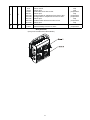
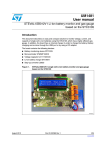
3.Description of the REDBlinder 2•48
1
1 - Mounting yoke
2 - "T" bar
3 - LED modules
2
3
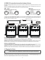
Control board
1 - 5-pin DMX output
2 - 3-pin DMX output
3 - 5-pin DMX input
4 - 3-pin DMX input
5 - LED display
6 - Mode-button
7 - Enter-button
8 - Up-button
9 - Down-button
10 - Fuse holder
11 - Mains input
4.Installation
4.1.Connection to the mains
The REDBlinder 2•48 is equipped with auto-switching power supply that automatically adjusts to any 50/60 Hz
AC power source from 100-240 volts.
Connect the REDBlinder 2•48 to the mains with the power cord.
If the plug on the flexible cord is not the right type for your socket outlets,do not use an adaptor,but remove the
plug from the cord and discard.Carefully prepare the end of the the supply cord and fit a suitable plug.
The earth has to be connected!
Cord plug connections:
Cable (EU)
Cable (US)
Pin
International
Brown
Black
Live L
Light blue
White
Neutral
N
Yellow/Green
Green
Earth
4.2 DMX-512 connection/connection between fixtures
The fixture is equipped with both 3-pin and 5-pin XLR sockets for DMX input and output.The sockets are wired
in parallel.
Only use a shielded twisted-pair cable designed for RS-485 and 3-pin or 5-pin XLR-plugs and connectors in
order to connect the controller with the fixture or one fixture with another.
DMX - output
XLR mounting-sockets (rear view):
1 - Shield
2 - Signal (-)
3 - Signal (+)
4 - Not connected
5 - Not connected
DMX-input
XLR mounting-plugs (rear view):
1 - Shield
2 - Signal (-)
3 - Signal (+)
4 - Not connected
5 - Not connected
If you are using the standard DMX controllers, you can connect the DMX output of the controller directly with
the DMX input of the first fixture in the DMX-chain. If you wish to connect DMX-controllers with other XLR-outputs, you need to use adapter-cables.
Master/slave operation
Controller operation
Building a serial DMX-chain:
Connect the DMX-output of the first fixture in the DMX-chain with the DMX-input of the next fixture. Always
connect one output with the input of the next fixture until all fixtures are connected.
Caution: At the last fixture, the DMX-cable has to be terminated with a terminator. Solder a 120 Ω resistor
between Signal (–) and Signal (+) into a 3-pin XLR-plug and plug it in the DMX-output of the last fixture.
Building a master/slave-chain:
Connect the DMX-output of the master fixture in the data-chain with the DMX-input of the first slave. Always
connect output with the input of the next slave until all slaves are connected (up to 9 fixtures).
Caution:It’s necessary to insert the XLR termination plug (with 120 Ohm) into the input of the master fixture
and into the output of the last slave fixture in the link in order to ensure proper transmission on the data link.
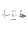
4.3 Rigging the fixture
Please consider the respective national norms during the installation!
The fixture should be hung on a truss structure using a mounting clamp (not included).Mounting yoke has a 13
mm diamer hole for fixing the mounting clamp.The fixture can be tilted + - 180°.The required tilt angle of the
fixture can be adjusted by means of the "T" bar on the side of the fixture.
The installation must always be secured with a secondary safety attachment, e.g. an appropriate cord .Fasten
the safety cord through the mounting yoke and over the trussing system.
When rigging, derigging or servicing the fixture staying in the area below the installation place, on bridges,
under high working places and other endangered areas is forbidden.
The operator has to make sure that safety-relating and machine-technical installations are approved by an expert
before taking into operation for the first time and after changes before taking into operation another time.
The operator has to make sure that safety-relating and machine-technical installations are approved by a skilled
person once a year.
The fixture should be installed outside areas where persons may walk by or be seated.
IMPORTANT! OVERHEAD RIGGING REQUIRES EXTENSIVE EXPERIENCE, including calculating working
load limits, installation material being used, and periodic safety inspection of all installation material and the
projector. If you lack these qualifications, do not attempt the installation yourself, but instead use a professional
structural rigger. Improper installation can result in bodily injury and.or damage to property.
If the fixture shall be lowered from the ceiling or high joists, professional trussing systems have to be used. The
fixture must never be fixed swinging freely in the room.
Caution: Fixtures may cause severe injuries when crashing down! If you have doubts concerning the safety
of a possible installation, do not install the fixture!
Before rigging make sure that the installation area can hold a minimum point load of 10 times the fixture’s
weight.
Danger of fire !
When installing the device, make sure there is no highly inflammable
material in a distance of min. 0.5m.
CAUTION!
Make sure that the device is fixed properly! Ensure that the
structure (truss)to which you are attaching the fixtures is secure.
Instal the device in a ventilated location.Never cover air vents!
4.4 Fitting the frost filtr
The REDBlinder 2•48 is supplied with clear glasses covering LED modules. If you wish to use a diffusive light
, it is possible to order glass or film frost filter sets and fix them on the LED modules by two fastenig
screws.
Glass filters- soft frost light
Film filters-dense frost light
Fastening screws
Glass (film) set
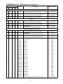
5.REDBlinder 2•48 - DMX protocol ,version 1.0
Mode/Channel
1
2
3
4
Value
Function
Type of control
Zone 1
1
1
0-255
Red LEDs 1
Red LEDs saturation control (0-100%)
2
2
0-255
Green LEDs 1
Green LEDs saturation control (0-100%)
proportional
3
3
0-255
Blue LEDs 1
Blue LEDs saturation control (0-100%)
proportional
proportional
Zone 2
4
4
0-255
Red LEDs 2
Red LEDs saturation control (0-100%)
proportional
5
5
0-255
Green LEDs 2
Green LEDs saturation control (0-100%)
proportional
0-255
Blue LEDs 2
Blue LEDs saturation control (0-100%)
proportional
6
6
Common channels for all Zones
7
1
1
0-255
Red LEDs
All red LEDs saturation control (0-100%)
proportional
2
2
0-255
Green LEDs
All green LEDs saturation control (0-100%)
proportional
3
3
0-255
Blue LEDs
All blue LEDs saturation control (0-100%)
proportional
0-7
8-15
16-23
24-31
32-39
40-47
48-55
56-63
64-71
72-79
80-87
88-95
96-103
104-111
112-119
120-127
128-135
136-143
144-151
152-159
160-167
168-175
176-183
184-191
192-199
200-207
208-215
216-223
224-231
232-239
240-247
248-255
MACRO SELECTION
No function
Macro 1
Macro 2
Macro 3
Macro 4
Macro 5
Macro 6
Macro 7
Macro 8
Macro 9
Macro 10
Macro 11
Macro 12
Macro 13
Macro 14
Macro 15
Macro 16
Macro 17
Macro 18
Macro 19
Macro 20
Macro 21
Macro 22
Macro 23
Macro 24
Macro 25
Macro 26
Macro 27
Macro 28
Macro 29
Mocro 30
Macro 31-rainbow effect from slow to fast
step
step
step
step
step
step
step
step
step
step
step
step
step
step
step
step
step
step
step
step
step
step
step
step
step
step
step
step
step
step
step
proportional
4
8
5
9
6
0-31
32-63
64-95
96-127
128-143
144-159
160-191
192-223
224-255
0-255
SHUTTER/STROBE
Shutter closed
Shutter open
Strobe-effect from slow to fast
Shutter open
Opening pulses in sequences from slow to fast
Closing pulses in sequences from fast to slow
Shutter open
Random strobe-effects from slow to fast
Shutter open
step
step
proportional
step
proportional
proportional
step
proportional
step
DIMMER
Dimmer intensity from 0% to 100%
proportional
Zone positions:
(every zone contains two LED modules)
6.REDBlinder 2•48 - Control menu map
Default settings=Bold print
A001 (001-504)
ProG
EPG.1
EPG.2
EPG.3
PrG.1
:
PrG.6
Auto (OFF,On)
Edit.
EPG.1
EPG.2
EPG.3
St.01
:
St.30
P.End
rEd (0-255)
:
dimr. (0-255)
F.tim.(0-255)
S.tim. (0-255)
COPY.
MAn.C.
rEd (0-255)
GrEE. (0-255)
bLuE (0-255)
:
MACr (0-255)
Stro. (0-255)
dimr. (0-255)
tESt
St.AL.
MASt.
SLA.
SPEC.
EPG.1
:
PrG.6
VErS.
tEMP
bALA. (On,OFF)
C.bAL.
rEd.b. (0..200..255)
GrE.b.(0..255)
bLu.b. (0..215..255)
dM.Pr.
Mod.1
Mod.2
Mod.3
Mod.4
i.bLi (On,Off
UPd.(no,YES)
10
7.Control board
The control panel situated on the top cover of the REDBlinder 2•48 allows DMX addressing,calling build-in
programs and setting the fixture behaviour.
Control elements on the control board:
[MODE] button-leaves menu without saving changes.
[ENTER] button- enters menu,confirms adjusted values and leaves menu.
[UP] button and[DOWN] button- moves between menu items on the the same level, sets values.
After switching the fixture on,the display shows the initial screen:
Use [UP],[DOWN] to browse through the menu. To select a function or submenu,press [ENTER].
7.1 Addressing the REDBlinder 2•48
The fixture can be uperated in the two modes:DMX mode-fixture is controlled via DMX 512 by an external
DMX controller
Stand-alone mode - fixture uses build-in programs and is able to control other fixtures in the master/slave chain.
See the chapter "Stand-alone mode" for detail description.
For DMX mode is important the DMX start address that is defined as the first channel from which the REDBlinder
2•48 will respond to the DMX controller.
Setting the DMX start channel for DMX operating:
1. Connect REDBlinder 2•48 to the mains.
2. Browse through the menu by pressing the [UP] and [DOWN] buttons until the display shows current addres
"A001".Confirm by pressing [ENTER] button and "A001" will start to flash frequently.
3. Use the [UP] and [Down] buttons to select the desired address.
4. Confirm by pressing [ENTER].After having addressed REDBlinder 2•48 , you may now start operating REDBlinder 2•48 via your DMX controller.
7.2 Program running
By enter to this menu a complete overview of all programs is offered,from which the program to be run can be
selected by pressing [ENTER] button.Selected program runs in a loop.The fixture includes 6 built-in programs
(PrG.1-PrG.6) and 3 free editable programs (EPG.1-EPG.3),each up to 30 steps.Each program step has a fade
time-the time during which effects go to the current step and a Standing time-the time,during which effects
last in the current step.
Programming procedure:
1. Enter "Edit." menu
2. Press [UP] or [DOWN] to select the desired program which you wish to edit and press [ENTER].
3. Press [UP] or [DOWN] to select the desired program step ("St.01" - "St.30") and press [ENTER].
4. Press [UP] or [DOWN] to select the desired item and press [ENTER]-button.Now you can edit by using [UP]
or [DOWN] buttons the DMX values of selected item:
P.End. - a total number of the program steps (value 1-30).This value you must set
before start programming(e.g. if you want to create program with 10 steps,set P.End=10).
rEd.1 - a red LEDs 1 saturation,value 0-255
rEd.2 - a red LEDs 2 saturation,value 0-255
GrE.1 - a green LEDs 1 saturation,value 0-255GrE.2 - a green LEDs 2 saturation,value 0-255
bLu.1 - a blue LEDs 1 saturation,value 0-255
bLu.2 - a blue LEDs 2 saturation,value 0-255
11
Following item are common for all zones:
MACr. - a macro selection,value 0-255
Stro. - a strobe,value 0-255
dimr. - a dimmer,value 0-255
F.tim. - fade time,value 0-255 *
S.tim. - standing time,value 0-255 *
COP. - copying the current prog. step to the next prog. step.
Press [ENTER]-button to confirm adjusted value .
5.Repeat steps 3 and 4 for next prog.step.If you want to copy current prog. step to the next prog.step, select
option "COPY."and confirm it by pressing [ENTER].
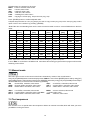
*Both Fade time and Standing time use the same conversion table in order to convert DMX value to the time
value:
DMX
Time
[sec.]
DMX
Time
[min.]
DMX
Time
[min.]
DMX
Time
[min.]
DMX
Time
[min.]
1
0.1
50
4.2
105
18.4
160
42.7
215
77
2
0.4
55
5
110
20.2
165
45.4
220
80.7
5
2.5
60
6
115
22
170
48.2
225
84.4
10
10
65
7
120
24
175
51
230
88.2
15
22.5
70
8.2
125
26
180
54
235
92
20
40
75
9.4
130
28.2
185
57
240
96
25
62.5
80
10.7
135
30.4
190
60.2
245
100
30
90
85
12
140
32.7
195
63.4
250
104
35
122.5
90
13.5
145
35
200
66.7
255
108
40
160
95
15
150
37.5
205
70
45
202.5
100
16.7
155
40
210
73.5
Exact expression of the time value follows the formula: time[sec.]=(DMX value)2/10.
If Item "AUto" is on,the fixture in DMX mode remembers last running program and this program will run after
switching on the fixture.
7.3 Manual mode
This menu gives access to the control of the fixture channels by means of the control buttons.
Use [UP] and [DOWN] buttons until the display shows "MAn.C." menu.Press [ENTER] button and by using [UP]
and [DOWN] buttons select desired effect,press [ENTER] and and by using [UP] and [DOWN] buttons adjust
desired DMX value for selected effect.Confirm by [ENTER].
rEd
- all red LEDs saturation,value 0-255
rEd.1 - a red LEDs 1 saturation,value 0-255
GrEE. - all green LEDs saturation,value 0-255
GrE.1 - a green LEDs 1 saturation,value 0-255
bLuE - all blue LEDs saturation,value 0-255
bLu.1 - a blue LEDs 1 saturation,value 0-255
rEd.2 - a red LEDs 2 saturation,value 0-255
GrE.2 - a green LEDs 2 saturation,value 0-255Stro.
bLu.2 - a blue LEDs 2 saturation,value 0-255
MACr. - a macro selection,value 0-255
- a strobe,value 0-255
dimr. - a dimmer,value 0-255
7.4 Test sequences
Use the item to run a special demo-test sequences without an external controller,which will show you some
possibilities of using the fixture.
12
7.5 Stand-alone mode
Synchronous operation of multiple fixtures requires that they must be connected on a data link and one of them is
set as a master ("MASt.") and the rest as the slaves ("SLA.").Only one fixture can be set as the master.The slaves
mimic the behavior of the master.Effect actions are triggered by an internal timer of the master fixture.
Important!:Disconect the fixtures from the DMX controller before master/slave operating ,otherwise data collisions can occur and the fixtures will not work properly!
MASt. --- Master.Enter this menu if you want to set the the fixture as a master.Use [UP] and [DOWN] buttons
to select desired program and press [ENTER] to confirm selection.
SLA. --- Slave.Enter this menu if you want to set the the fixture as a slave.
The master fixture starts simultaneous program start in the other slave fixtures.All fixtures are synchronized in
every prog.steps.The fixtures run their programs repeatedly (e.g. if master runs its program "PrG.5",all slaves
will be executed program "PrG.5" too).
7.6 Special functions
Use this menu for special services.
VErS. --- Software Version.Select this function to read the number of the fixture software.
tEMP. --- Fixture temperature.Current temperature on PCB board.
bALA. --- Balance.Select this function to enable (On) or disable (OFF) the white balance which is set in "White
colour balance" menu below.If this function is set OFF,REDBlinder 2•48 will use maximum values (255) of
saturation for red, green and blue channel.
C.bAL. --- White colour balance. Using this menu you can set white balance:
1. Browse through the menu by pressing the [UP] and [DOWN] buttons until the display shows "C.bAL."
menu.Press [ENTER] button and "rEd.b." will appear on the display.
2.Press [ENTER] button again and use [UP] and [DOWN] buttons to adjust the new maximum value required
for the red channel.Confirm your choice by pressing [ENTER].Use the [UP] and [Down] buttons to select next
colour.
3.Repeat step 2 for green channel "GrE.b." and for blue channel "bLu.b".
dM.Pr. --- DMX presetting.The function makes possible to select from the 4 DMX- channels settings.Use [UP]
and [DOWN] buttons to select desired channel modes (“Mod.1,Mod.2,Mod.3,Mod.4”) and press [ENTER] to
confirm.For detail description of all channels see DMX protocol.
i.bLi. --- Initial blink.If this function is on,Led Blinder 248 LT makes auto-calibration (All LEDs light on 100% for
a short time) after switching it on.If this function is set off,you have to set manually every colour on max.brightness after switching on the driver before starting regular operating.This action should last min. one second.
UPd. --- Software update - Using this function you can update software in the fixture via PC and serial link.
The following are required in order to update software:
- PC running Windows 95/98/2000/XP or Linux
- DMX Software Uploader
- Flash cable RS232/DMX (No.13050624)
Note1:Software update should execute a qualified person.If you lack qualification, do not attempt the update
yourself and ask for help your ROBE distributor.
Note 2:DMX address,programs and all settings will be set to their default values
To update software in the fixture:
1.Installation of DMX Software Uploader:
13
1.DMX Software Uploader program is available from the ROBE web site at WWW.robe.cz.
2.Make a new directory ( e.g. Robe_Uploader) on your hard disk and download the software to it.
3.Unpack the program from the archive. Program file has name:DSU_name of corresponding
fixture_SoftwareID.SoftwareID describes the versions of fixture software included in DMX Software Uploader. Higher number means later software versions.
2.Fixture software updating:
1.Determine which of your COM port is available on your PC and connect it with to the DMX input
of the fixture using the Flash cable. Do not extend this cable! Disconnect the fixture from the
other fixtures in DMX chain! Turn on the computer and the fixture.
2.Switch the fixture to the update mode by selecting the option Software update in menu Special
Functions on the fixture control panel:SPEC-->UPd-->yES.(From this option you cannot return back
to the main menu. If you do not want to continue in software update, you have to switch off and on
the fixture to leave this option!)
3.It is recommended that you exit all programs before running the Software Uploader.
4.Start the Software Uploader program. Select desired COM and then click Connect button.
If the conection is OK, click Start Uploading button to start uploading. It will take several minutes to perform software update.All processors will be updated (including processors with the same software version).
If you wish to update only later versions of processors, enable the Incremental Update check box.
Avoid interrupting the process. Update status is being displayed in the list window.
When the update is finished, the line with the text “The fixture is successfuly updated‘ will appear
in this window and the fixture will reset with the new software.
Note: In the case of interruption of the upload process (e.g. power cut), the fixture remains in the update mode
and you have to repeat the software update again.
For example: The fixture was switched off before finishing software upload. After switching the fixture on again,
the fixture is still in the update mode and the display is dark. Restart the Software Uploader program and repeat
software update from your PC.
14
Technical Specifications
Power supply:
Input Voltage:100-240V AC, 50/60 Hz
Fuse:T 2 A
Max.Pover Consumption: 135 VA
Input:
Control:DMX 512
DMX connection: 3-pin or 5-pin XLR-sockets
DMX channels:
3,6 or 9 channels; 4 DMX protocol modes
LED device:
Luxeon K2
2 pairs of 12-LEDs modules
LED beam angle:
Each LED has 25° beam angle
Control and programming:
Protocol: USITT DMX-512
Control options:DMX,Auto-trigger
Operation modes:Master/Slave,Stand alone
Programs:6 build-in programs+3 user editable programs up to 30 steps each
Display:4 digit LED
White colour balance adjusting
Manual control of all DMX channels with LED control panel
Temperatures
Maximum ambient temperature : 40° C
Maximum housing temperature : 80 °C
Minimum distances
Min.distance from flammable surfaces: 0.5m
Min.distance to lighted object: 1.3 m
Dimensions(mm):
Weight:
13 kg
15
Optional Accessories
Set glass frost (No.99011539).................4 pieces
Set film frost (No.99011540)....................4 pieces
9.Maintenance
Keep the Led Blinder 248 LT dry.
Operate only in places where the sufficient airflow to cool the fixture is present
Periodically clean the front transparent cover of LED modules
Use a moist, lint-free cloth. Never use alcohol or solvents!
In order to maintain adequate cooling,dust must be cleaned from the air vents.
Replacing the fuse
1.Before replacing the fuse, unplug mains lead!
2.Unscrew the fuse holder on the rear side of the REDBlinder 2•48 with a fitting screwdriver from the housing
(anti-clockwise).
3.Remove the old fuse from the fuse holder.
4.Install the new fuse in the fuse holder.
5.Replace the fuse holder in the housing and fix it.
Specifications are subject to change without notice.
16
17