1
Application
PowerSecurity
EN*
Edition: 6 from 18.08.2014
Supercedes the edition: 5 from 08.01.2013
www.pulsar.pl
PowerSecurity
TABLE OF CONTENTS
1. GENERAL DESCRIPTION ...................................................................................................................3
2. CONFIGURING THE CONNECTION. ...............................................................................................4
2.1 THE WI-FI WIRELESS COMMUNICATION. ............................................................................................................................... 5
2.2 ETHERNET NETWORK COMMUNICATION. ........................................................................................................................... 6
2.3 RS485 NETWORK COMMUNICATION. ..................................................................................................................................... 7
2.4 USB-TTL COMMUNICATION. ................................................................................................................................................ 7
3. APPLICATION INTERFACE SPECIFICATIONS. ...........................................................................8
3.1 THE MENU BAR. .................................................................................................................................................................. 8
3.2 MANAGER WINDOW. ............................................................................................................................................................. 9
3.3 REMOTE DESKTOP WINDOW................................................................................................................................................... 9
4. WINDOW MONITORING THE PSBEN POWER SUPPLY PARAMETERS. ............................10
4.1 THE „PREVIEW” TAB ........................................................................................................................................................... 10
4.2 THE „DIAGRAMS” TAB ........................................................................................................................................................ 11
4.3 THE „HISTORY’’ TAB........................................................................................................................................................... 12
4.3.1 Reading the history of events of the power supply with LED display. ......................................................................... 12
4.3.2 Reading the history of events of the power supply with LCD display. ........................................................................ 13
4.4 REMOTE BATTERY TEST....................................................................................................................................................... 14
5. WINDOW MONITORING THE EN54 POWER SUPPLY PARAMETERS. ................................15
5.1 THE „PREVIEW” TAB ........................................................................................................................................................... 15
5.2 THE „DIAGRAMS” TAB ........................................................................................................................................................ 17
5.3 THE „HISTORY’’ TAB........................................................................................................................................................... 18
5.3.1 Reading the history of events of the power supply with LED display. ......................................................................... 18
5.3.2 Reading the history of events of the power supply with LCD display. ........................................................................ 19
5.4 REMOTE BATTERY TEST....................................................................................................................................................... 20
APPENDIX A – FAILURE CODES OF THE PSBEN 13,8V POWER SUPPLY...............................21
APPENDIX B – FAILURE CODES OF THE PSBEN 27,6V POWER SUPPLY ...............................22
APPENDIX C – FAILURE CODES OF THE EN54 27,6V POWER SUPPLY ..................................23
2
www.pulsar.pl
PowerSecurity
1. General description
The PowerSecurity is a program which enables a remote monitoring of the parameters of power supplies of
the PSBEN and EN54 series, which feature a communication interface. In addition, the program enables combining
power supply units, previewing the PSU’s status, reading the event log and diagrams of electrical parameters and
remote battery test.
For proper operation of the software, a PC with Windows XP or newer is required.
.
The "PowerSecurity" program can be downloaded at
http://www.pulsar.pl/pliki/PowerSecurity.exe
3
www.pulsar.pl
PowerSecurity
2. Configuring the connection.
In order to configure the connection between the PSU and the PowerSecurity program, choose the
“New Power Supply” option from the “Power Supplies” menu.
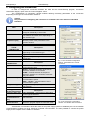
The “Configuration of connection” window enables defining necessary parameters of the connection
depending on the type of communication interface.
Caution.
Full procedure of configuring the connection is included in the user manual of individual
interfaces.
PSU
Name
Address
Refresh period of
the preview [ms]
MODBUS RTU –
TCP/IP
CONNECTION
Type
TCP Address
Port TCP
MODBUS RTU
CONNECTION
Type
Port
Transmission speed
Parity checking
Timing parameters
of the transmission
Response time [ms]
The interval between
the transmissions
[ms]
The number of
retransmissions
Description
PSU’s name - The name that should be
assigned individually to each PSU.
1 ÷ 247;
The address of another PSU, depending on
the interface type.
100 ÷ 60 000ms;
Refresh period of the parameters in the
preview window.
Description
Modbus RTU – TCP/IP - connection type,
depending on the interface type.
e.g. 192.168.1.100 - TCP connection address.
e.g. 2101 - A port assigned to the TCP
connection.
Fig. 1. The connection configuration
window - the Modbus RTU-TCP/IP
connection.
Description
Modbus RTU - connection type, depending
on the interface type.
AUTO – automatic detection of the port to
which the interface is connected.
COMx – manual selection of the port to
which the interface is connected, X denotes
the port number.
AUTO – Automatic detection of the
communication speed.
9600 - 115,200 – manual selection of the
communication speed.
Parity – checking the parity of the
transmission.
Description
100 ÷ 60 000ms – response time depending
on the type of interface.
0 - The minimal interval between
transmissions.
3 - The number of retransmissions after
which the program reports a connection error.
Fig. 2.The connection configuration
window – the Modbus RTU connection.
Transmission of information about the status of the power supply system is enabled by the use of PULSAR
communications modules for Wi-Fi, Ethernet of RS485 communication. It is also possible to connect the power
supply to the computer via the USB-TTL interface.
4
www.pulsar.pl
PowerSecurity
2.1 The Wi-Fi wireless communication.
The Wi-Fi wireless communication can be implemented on the basis of additional interfaces: Wi-Fi „INTW” and
RS485-WiFi, operating within 2,4GHz frequency band, according to the IEEE 802.11 bgn standard.
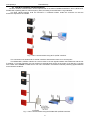
The WiFi “INTW” interface shall be mounted in a selected location inside the enclosure so that the
antenna is exposed to the outside.
Fig. 3. Wi-Fi communication using WI-FI „INTW” interface.
The connection uses wireless Wi-Fi "INTW" interface and wireless router as an access point.
The RS485-WiFi „INTRW” interface is a device used to convert signals between the RS485 bus and the WiFi network. For proper operation, the unit requires an external power supply in the range of 10÷30V DC e.g. drawn
from a PSU of the PSBEN or EN54 series. The unit is mounted in a hermetic enclosure protecting against adverse
environmental conditions.
Fig. 4. Wi-Fi communication using the RS485-WiFi „INTRW” interface.
5
www.pulsar.pl
PowerSecurity
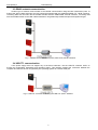
2.2 ETHERNET network communication.
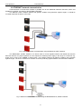
Communication in the Ethernet network is possible due to the additional interfaces: Ethernet „INTE” and
RS485-ETH „INTRE”, according to the IEEE802.3 standard.
The Ethernet „INTE” interface features full galvanic isolation and protection against surges. It should be
mounted inside the enclosure of the PSU.
Fig. 5. Ethernet network communication using the Ethernet „INTE” interface.
The RS485-WiFi „INTRE” interface is a device used to convert signals between the RS485 bus and the
Ethernet network. For proper operation, the unit requires an external power supply in the range of 10÷30V DC e.g.
drawn from a PSU of the PSBEN or EN54 series. The interface features full galvanic isolation and protection
against surges. The unit is mounted in a hermetic enclosure protecting against adverse environmental conditions.
Fig. 6. Ethernet network communication using the RS485-Ethernet „INTRE” interface.
6
www.pulsar.pl
PowerSecurity
2.3 RS485 network communication.
Another type of network communication is the RS485 communication using two-wire transmission path. To
achieve this kind of data exchange, the PSU should be equipped with the additional RS485 TTL "INTR" interface,
converting data from the PSU into the RS485 standard and the USB-RS485 "INTUR" interface, converting data
from the RS485 network to the USB. Offered interfaces are galvanically isolated and protected against surges.
Fig. 7. RS485 communication using the „INTR” and „INTUR” interface.
2.4 USB-TTL communication.
If the power supply does not support any of the above networks, use the USB-TTL interface "INTU" to
access the configuration parameters and operation history. This interface enables the connection between the
computer and the PSU and is recognized by the operating system as a virtual COM port.
Fig. 8. USB-TTL communication using the USB-TTL „INTU” interface.
7
www.pulsar.pl
PowerSecurity
3. Application Interface Specifications.
The main interface of the PowerSecurity program is the standard window with the elements and the
corresponding functions assigned in an intuitive way. The application allows to configure the connections, analyze
the parameters and manage large numbers of power supplies.
remote desktop of PSU PSBEN
remote desktop of PSU EN54
menu bar
manager
window
Fig. 9. The „Power security” window.
The main panel can be divided into smaller areas, depending on the number of monitored power supplies.
The program includes a manager mode, which allows combining power supplies for easier analysis and
orientation regarding the assignment to the selected areas.
The application allows both the visualization and analysis of the received data. Exceeding the permissible
parameters is indicated by indicated by highlighting in red the appropriate area or by flashing warning light. The
individual tabs allow to show the power supply parameters on the graph and to read the history of events, along
with information about the current state of technical outputs and electrical parameters.
3.1 The MENU bar.
The tabs on the menu bar allow changing the interface language, saving and reading the current
configuration and the management of open windows.
The „Power Supplies”
Menu
New Power Supply
Load settings
Save settings
Exit
Adding a new power supply
Load saved settings from a file
Save all settings to a file
Exit the program
The „Windows’’ Menu
Horizontal
Vertical
Align
Horizontal alignment of windows
Vertical alignment of windows
Alignment of windows on the space
available in the main window
8
www.pulsar.pl
PowerSecurity
The „Language” Menu
Allows to choose a language
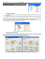
3.2 Manager window.
The manager window allows to combine the monitored power supplies, giving greater control in case of
more complex systems.
During normal operation of the system where all of the connected power supplies are working correctly and
do not signal any failures, the names of power supplies are displayed in black (see picture below – Power Supply
1).
If the connection with the power supply has been intentionally disconnected, the power supply is displayed in gray,
indicating that the connection with the power supply is disabled (see figure below - Power Supply 3).
In the case of failure of power supply while monitoring the system, the name and the group of a given power supply
unit will be highlighted in red (see picture below - Power Supply 2).
Fig. 10. Status indication of the monitored power supplies.
3.3 Remote desktop window.
Remote desktop window of the power supplies displays the panels of the monitored power supplies.
Depending on the type of power supply (power supplies of the PSBEN or EN54 series), the program opens the
desktop, automatically choosing its appearance and displayed parameters.
The position of the remote desktop window can be set via the "Windows" menu bar.
Fig. 11. Remote desktop windows of the power supplies: PSBEN (left), EN54 (right),
9
www.pulsar.pl
PowerSecurity
4. Window monitoring the PSBEN power supply parameters.
The window monitoring the PSU parameters appears after configuring a new connection or after
loading the previously saved configuration. The window contains the title bar with the name of the connected PSU
and the menu bar divided into three tabs: preview, charts and history.
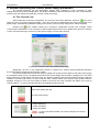
4.1 The „Preview” tab
After loading the connection configuration, the ”Preview” tab will be displayed. Press the
icon in the
upper left corner to connect the power supply. Once the connection is established, the current parameters of the
power supply, automatically updated according to the refresh cycle set during configuration, will be displayed.
Pressing the
icon enables opening the connection configuration window and changing certain
communication parameters. If it is necessary to edit the parameters that are not available from this level, close the
current connection and open a new one ("New power supply" from the main window).
Fig. 12. The „Preview” tab of the PSBEN power supply.
Graphically, the tab of the parameters preview is divided into sections, which symbolically represent
the most important components of the power system
The electrical parameters at the AUX output (voltage and current) and the status of the 230V mains supply
are monitored. What is more, the battery block shows the actual voltage and the battery charging level. The TEST
button performs a remote battery test at any time. The graphic symbols of the technical outputs of power supply are
located in the lower right corner. In case of failures, their contacts switch from closed to open position and the
backlight changes to red. The EXT window located in the lower left corner indicates the status of the input of
collective failure – in case of the input activation its backlight changes into red.
Mains supply status:
230V mains supply ON: OK.
No 230V mains supply
Electrical parameters at the AUX output of the PSU:
- output voltage [V]
- output current [A]
- output fuse status
In case of the fuse activation, the symbol changes into red and
flashes
10
www.pulsar.pl
PowerSecurity
Information window with the PSU type
Current battery status:
- battery voltage [V]
- charging level
- TEST; performing battery test (see section 4.4)
- battery fuse status
In case of the fuse activation, the symbol changes to red and
flashes.
Input of collective failure EXT IN status.
In case of the input activation, its backlight changes into red.
Status of the technical outputs of the PSU.
EPS - AC power ON indication
open, red backlight
closed, green backlight
PSU – PSU failure indication
open, red backlight
closed, green backlight
APS – battery failure indication
open, red backlight
closed, green backlight
= AC power failure
= AC power ON:OK.
= failure
= PSU status OK.
= battery failure
= battery OK.
Failure example, the output is open and highlighted in red.
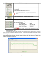
4.2 The „Diagrams” tab
The ”Diagrams” tab enables reading the history of the parameters (current, voltage) stored in the internal
memory of the PSU and reading the values from the charts. The ”Diagrams” tab is available only for power supplies
with LCD display.
During normal operation, the PSU records the voltage and current values at the AUX output circuit and
saves them in the internal nonvolatile memory. Recording is performed at 5 minute intervals and the memory
capacity allows for about 6100 entries. The data is stored in the circular buffer: when the memory is full, the oldest
entries are overwritten by the new ones.
Fig. 13. The „Diagrams” tab.
11
www.pulsar.pl
PowerSecurity
To read the internal memory of the power supply, press the
button in the upper left corner. Depending
on the amount of data recorded, the reading can take from a few seconds up to several minutes. The reading starts
from the most recent entries and its progress is displayed as a percentage value. The reading can be stopped at
any time by pressing the
button.
The diagram presents the following parameters:
- Uaux
- output voltage (mean value within 5 minutes)
- Uaux min
- minimum output voltage
- Uaux max
- maximum output voltage
- Ubat
- battery voltage (mean value within 5 minutes)
- Iaux
- output current (mean value within 5 minutes)
- Iaux max
- maximum output current
- Iaux min
- minimum output current
The chart’s color corresponds to the color of the label located below.
To indicate whether the individual minimum, maximum or average values should be visible on the diagram, use the
toolbar icons, e.g.
.
The diagram window can be scaled by pressing the left mouse button and selecting the area to be
enlarged. To enlarge the selected diagram, press the mouse button and move the mouse from left to right. To
return to normal scale, move the mouse from right to left.
The program enables storing the read data for further analysis. Press the
button to save the data in
.csv or .dat format, allowing reloading and displaying data in a chart window.
The information about the type of power supply, its position in the manager list and the communication
address can be obtained by pressing the
from another PSU.
button. This information is particularly useful when importing a file
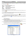
4.3 The „History’’ tab
The „History’’ tab enables reading the history of events stored in the memory of the PSU in case of any
incorrect parameters during operation.
There are two history windows available, depending on the type of power supply:
- The power supplies with seven-segment LED can display the history of the last 30 events.
- The power supplies with LCD displays are fitted with an additional memory system that allows storing
over 2000 events containing more detailed information about the status of the power supply.
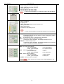
4.3.1 Reading the history of events of the power supply with LED display.
To read the history of events of the power supply with LED display press the
starts from the most recent entries. The reading can be stopped at any time by pressing the
Fig. 14. The „History’’ tab.
12
button. The reading
button.
www.pulsar.pl
PowerSecurity
The table of the history of events of the power supply includes information about:
The time elapsed since the event – the time that has elapsed since the occurrence of the event. For example
4h 54m means that the event occurred 4 hours and 54 minutes ago.
In case of power loss (no 230V AC mains supply) during the PSU operation while the battery is
not connected or fully discharged, the information about the time until the next switch of the
power supply is lost. In such a case, an asterisk symbol appears next to the time display, e.g.
4h 53m *, informing about the situation.
Event description – event code and its description. Appendixes A, B and C at the end of the manual
summarize all the failure and event codes that may occur during the power supply operation.
The individual codes are accompanied by appropriate optical indication on the panel, acoustic
indication and activation of the dedicated technical output.
Uaux, Iaux – output voltage and output current saved in the memory at the time of a given event.
The program enables storing the read data for further analysis. Press the
button to save the data in
.csv or .dat format, allowing reloading and displaying data in a chart window.
The information about the type of power supply, its position in the manager list and the communication
address can be obtained by pressing the
from another PSU.
button. This information is particularly useful when importing a file
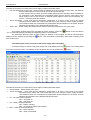
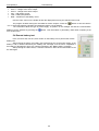
4.3.2 Reading the history of events of the power supply with LCD display.
To read the history of events of the power supply with LCD display press the
from the most recent entries. The reading can be stopped at any time by pressing the
button. The reading starts
button.
Fig. 15. The „History’’ tab.
The table of the history of events of the power supply includes information about:
Time and date – date and time of the event
Event description – event code and its description. Appendixes A, B, and C at the end of the manual
summarize all the failure and event codes that may occur during the power supply operation.
The individual codes are accompanied by appropriate optical indication on the panel, acoustic
indication and activation of the dedicated technical output.
AC – AC 230V power indication:
ON = AC power on
OFF = AC power off
LB – battery charging indication
ON = battery charging
OFF = no charging, battery fully charged
EXTi – status of the technical input
ON = input activated
OFF = input not activated
13
www.pulsar.pl
•
PowerSecurity
EPS – technical output indicating AC power loss
open
= AC power loss
closed
= AC power - OK.
PSU – technical output indicating PSU failure
open
= failure
closed
= PSU operation - OK.
APS – technical output indicating battery failure
open
= battery failure
closed
= battery OK.
Uaux (avg)– output voltage, mean value
Iaux (avg) output current, mean value
Ubat – battery voltage
Use the “Filter” menu on the toolbar to filter the displayed events by the selected event code.
The program enables storing the read data for further analysis. Press the
button to save the data in
.csv or .dat format, allowing reloading and displaying data in a chart window.
The information about the type of power supply, its position in the manager list and the communication
address can be obtained by pressing the
from another PSU.
button. This information is particularly useful when importing a file
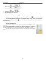
4.4 Remote battery test
In the „Preview” tab, use the „TEST” button on the battery icon to perform the remote
battery test.
After pressing the button, the battery test command is sent to the power supply. If the
battery is OK, it will be indicated by the ”Battery OK” message once the test is completed. If
the battery is discharged or worn out, it will be indicated by the ”Battery failure” message.
The battery test will not be performed if the PSU is not configured to operate without
battery.
14
www.pulsar.pl
PowerSecurity
5. Window monitoring the EN54 power supply parameters.
The window monitoring the PSU parameters appears after configuring a new connection or after
loading the previously saved configuration. The window contains the title bar with the name of the connected PSU
and the menu bar divided into three tabs: preview, charts and history.
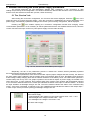
5.1 The „Preview” tab
After loading the connection configuration, the ”Preview” tab will be displayed. Press the
icon in the
upper left corner to connect the power supply. Once the connection is established, the current parameters of the
power supply, automatically updated according to the refresh cycle set during configuration, will be displayed.
Pressing the
icon enables opening the connection configuration window and changing certain
communication parameters. If it is necessary to edit the parameters that are not available from this level, close the
current connection and open a new one ("New power supply" from the main window).
Fig. 16. The „Preview” tab of the EN54 power supply.
Graphically, the tab of the parameters preview is divided into sections, which symbolically represent
the most important components of the power system.
The electrical parameters at the AUX1 and AUX2 outputs (output voltages and total current), the status of
the 230V mains supply (ON/OFF) and the voltage value are monitored. What is more, the battery block shows the
actual voltage, battery charging level and the internal resistance of the battery circuit. The TEST button performs a
remote battery test at any time. The graphic symbols of the technical outputs of power supply are located in the
lower right corner. In case of failures, their contacts switch from closed to open position and the backlight changes
to red. The EXTi window located in the central part indicates the status of the input of collective failure – in case of
the input activation its backlight changes into red. The EXTo window indicates the status of the controlled relay
output - if the relay is activated, it changes to red. The TAMPER window indicates the status of the tamper input –
in case of open circuit (enclosure opening) its backlight changes into red.
.
Mains supply status (mains supply value)
230V mains supply:
- green backlight if the voltage is in the range between 230V -15% - +10%
- blue backlight if the voltage is below 230V – 15%
- red backlight if the voltage is over 230V +10%
No 230V mains supply
15
www.pulsar.pl
PowerSecurity
Electrical parameters at the AUX outputs of the PSU:
- output voltage at the AUX1 output [V]
- output voltage at the AUX2 output [V]
- total output current
- the fuse status at the AUX1 output
- the fuse status at the AUX2 output
In case of fuse activation, the symbol changes to red and flashes.
Information window with the PSU type
Current battery status:
- battery voltage [V]
- charging level
- TEST: performing battery test (see section 5.4)
- battery fuse status
- battery temperature
- resistance of the battery circuit
In case of fuse activation, the symbol changes to red and flashes.
EXTo - controlled relay output EXTo status.
its backlight changes into red and the contacts change their position
(C closed with NO)
On – the start button of the controlled relay output EXTo.
EXTi – input of the collective failure EXTi status.
In case of the input activation, its backlight changes into red.
TAMPER – TAMPER input status.
In case of the input activation, its backlight changes into red and the
contacts change their position (opening).
Status of the technical outputs of the PSU.
EPS - AC power ON indication
open, red backlight
closed, green backlight
PSU – PSU failure indication
open, red backlight
closed, green backlight
APS – battery failure indication
open, red backlight
closed, green backlight
ALARM – collective failure indication
= AC power failure
= AC power ON:OK.
= failure
= PSU status OK.
= battery failure
= battery OK.
Fault example, the output is open and highlighted in red.
16
www.pulsar.pl
PowerSecurity
5.2 The „Diagrams” tab
The ”Diagrams” tab enables reading the history of the parameters (current, voltage) stored in the internal
memory of the PSU and reading the values from the charts. The ”Diagrams” tab is available only for power supplies
with LCD display.
During normal operation, the PSU records the voltage and current values at the AUX output circuit and
saves them in the internal nonvolatile memory. Recording is performed at 5 minute intervals and the memory
capacity allows for about 6100 entries. The data is stored in the circular buffer: when the memory is full, the oldest
entries are overwritten by the new ones.
Fig. 17. The „Diagrams” tab.
To read the internal memory of the power supply, press the
button in the upper left corner. Depending
on the amount of data recorded, the reading can take from a few seconds up to several minutes. The reading starts
from the most recent entries and its progress is displayed as a percentage value. The reading can be stopped at
any time by pressing the
button.
The diagram presents the following parameters:
- Uaux1 avg - AUX1 output voltage (mean value within 5 minutes)
- Uaux1 min - minimum output voltage at the AUX1
- Uaux1 max - maximum output voltage at the AUX1
- Uaux2 avg
- Uaux2 min
- Uaux2 max
- AUX2 output voltage (mean value within 5 minutes)
- minimum output voltage at the AUX2
- maximum output voltage at the AUX2
- Uac avg
- Uac min
- Uac max
- mains supply (mean value within 5 minutes)
- minimum mains supply
- maximum mains supply
- Ubat
- Ubat min
- Ubat max
- battery voltage (mean value within 5 minutes)
- minimum battery voltage
- maximum battery voltage
- Iaux
- Iaux max
- Iaux min
- total output current (mean value within 5 minutes)
- maximum total output current
- minimum total output current
- Tbat - battery temperature
- Rbat - resistance of the battery circuit
The chart’s color corresponds to the color of the label located below.
To indicate whether the individual minimum, maximum or average values should be visible on the diagram, use the
toolbar icons, e.g.
.
17
www.pulsar.pl
PowerSecurity
The diagram window can be scaled by pressing the left mouse button and selecting the area to be
enlarged. To enlarge the selected diagram, press the mouse button and move the mouse from left to right. To
return to normal scale, move the mouse from right to left.
The program enables storing the read data for further analysis. Press the
button to save the data in
.csv or .dat format, allowing reloading and displaying data in a chart window.
The information about the type of power supply, its position in the manager list and the communication
address can be obtained by pressing the
from another PSU.
button. This information is particularly useful when importing a file
5.3 The „History’’ tab
The „History’’ tab enables reading the history of events stored in the memory of the PSU in case of any
incorrect parameters during operation.
There are two history windows available, depending on the type of power supply:
- The power supplies with seven-segment LED can display the history of the last 30 events.
- The power supplies with LCD displays are fitted with an additional memory system that allows storing
over 2000 events containing more detailed information about the status of the power supply.
5.3.1 Reading the history of events of the power supply with LED display.
To read the history of events of the power supply with LED display press the
from the most recent entries. The reading can be stopped at any time by pressing the
button. The reading starts
button.
Fig. 18. The „History” tab.
The table of the history of events of the power supply includes information about:
The time elapsed since the event – the time that has elapsed since the occurrence of the event. For example
4h 54m means that the event occurred 4 hours and 54 minutes ago.
In case of power loss (no 230V AC mains supply) during the PSU operation while the battery is
not connected or fully discharged, the information about the time until the next switch of the
power supply is lost. In such a case, an asterisk symbol appears next to the time display e.g. 4h
53m *.
Event description – event code and its description. Appendixes A, B and C at the end of the manual
summarize all the failure and event codes that may occur during the power supply operation.
The individual codes are accompanied by appropriate optical indication on the panel, acoustic
indication and activation of the dedicated technical output.
Uaux, Iaux – output voltage and output current saved in the memory at the time of a given event.
18
www.pulsar.pl
PowerSecurity
The program enables storing the read data for further analysis. Press the
button to save the data in
.csv or .dat format, allowing reloading and displaying data in a chart window.
The information about the type of power supply, its position in the manager list and the communication
address can be obtained by pressing the
from another PSU.
button. This information is particularly useful when importing a file
5.3.2 Reading the history of events of the power supply with LCD display.
To read the history of events of the power supply with LCD display press the
from the most recent entries. The reading can be stopped at any time by pressing the
button. The reading starts
button.
Fig. 19. The „History” tab.
The table of the history of events of the power supply includes information about:
Time and date – date and time of the event
Event description – event code and its description. Appendixes A, B and C at the end of the manual
summarize all the failure and event codes that may occur during the power supply operation. The individual
codes are accompanied by appropriate optical indication on the panel, acoustic indication and activation of
the dedicated technical output.
AC – AC 230V power indication:
ON = AC power on
OFF = AC power off
LB – battery charging indication
ON = battery charging
OFF = no charging, battery fully charged
EXTi – external failure input
ON = failure
OFF = normal status
EPS – technical output indicating AC power loss
Open = AC power loss
closed = AC power - OK.
PSU – technical output indicating PSU failure
open = failure
closed = PSU operation - OK
APS – technical output indicating battery failure
open = battery failure
closed = battery OK
EXTo – controlled relay output
open = output on
closed = output off
ALARM – technical output of collective failure
Open = AC power loss
closed = AC power - OK.
19
www.pulsar.pl
PowerSecurity
Uac – 230V AC mains supply voltage
Uaux1 – voltage at the AUX1 output
Uaux2 - voltage at the AUX1 output
Iaux – total output current
Tbat – battery temperature
Rbat – resistance of the battery circuit
Use the “Filter” menu on the toolbar to filter the displayed events by the selected event code.
The program enables storing the read data for further analysis. Press the
button to save the data in
.csv or .dat format, allowing reloading and displaying data in a chart window.
The information about the type of power supply, its position in the manager list and the communication
address can be obtained by pressing the
from another PSU
.
button. This information is particularly useful when importing a file
5.4 Remote battery test
In the „Preview” tab, use the „TEST” button on the battery icon to perform the remote
battery test.
After pressing the button, the battery test command is sent to the power supply. If the
battery is OK, it will be indicated by the ”Battery OK” message once the test is completed. If
the battery is discharged or worn out, it will be indicated by the ”Battery failure” message.
After pressing the TEST button, it remains inactive for about 30 seconds before it can
be used again.
20
www.pulsar.pl
PowerSecurity
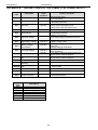
APPENDIX A – FAILURE CODES OF THE PSBEN 13,8V POWER SUPPLY
Failure
code
Information
Technical
output
activation
F01
No AC power!
EPS FLT
F02
AUX Fuse!
PSU FLT
F03
BAT fuse!
APS FLT
F04
Output overload!!
F05
Faulty battery!
F06
High AUX voltage!
F07
High battery voltage!
PSU FLT
F08
Battery charging
circuit failure!
PSU FLT
F09
Low AUX voltage!
PSU FLT
F10
F11
F12
F13
F50-F54
F60
F61-F64
F65
Event
code
I00
I01
I02
I03
I04
I05
I06
PSU FLT
APS FLT
PSU FLT
APS FLT
Low battery voltage!
Low battery voltage –
off!
EXT external input!
PSU enclosure
opening!
Internal damage of the
PSU.
No communication
APS FLT
ALARM
Causes, comments
- No AC mains supply
- FMAIN fuse failure
- Blown FAUX fuse
- AUX output overload
- Blown FBAT fuse
- Short circuit in the battery circuit
- Short circuit in the AUX output circuit
- PSU overload
- Worn out batteries
- Undercharged batteries
- Battery not connected
- The output voltage of the PSU over 14.7V
- Battery voltage >14V
- The output voltage of the PSU set too low , below
13V
- Battery charging circuit failure
- The output voltage below 11.8V (during buffer
operation)
- The battery voltage has dropped below 11.5V
(during battery-assisted operation)
- the battery voltage has dropped below 10V (during
battery-assisted operation)
- Activation of the input of collective failure: EXT IN
PSU FLT
LCD damage
Access unlocked
PSU FLT
- service codes
PSU FLT
- no communication with LCD panel
PSU FLT
- service codes
- passwords unlocked
Description
PSU start-up
AC power restored
AUX fuse replaced
BAT fuse replaced
Battery status: OK
Battery test – START
Enclosure closed
21
www.pulsar.pl
PowerSecurity
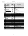
APPENDIX B – FAILURE CODES OF THE PSBEN 27,6V POWER SUPPLY
Failure
code
Information
Technical
output
activation
F01
No AC power!
EPS FLT
F02
AUX Fuse!
PSU FLT
F03
BAT fuse!
APS FLT
F04
Output overload!!
PSU FLT
F05
Faulty battery!
F06
High AUX voltage!
F07
High battery voltage!
PSU FLT
F08
Battery charging
circuit failure!
PSU FLT
F09
Low AUX voltage!
PSU FLT
F10
F11
F12
F13
F50-F54
F60
F61-F64
F65
Event
code
I00
I01
I02
I03
I04
I05
I06
Low battery voltage!
Low battery voltage –
off!
EXT external input!
PSU enclosure
opening!
Internal damage of the
PSU.
No communication
LCD damage
Causes, comments
- No AC mains supply
- FMAIN fuse failure
- Blown FAUX fuse
- AUX output overload
- Blown FBAT fuse
- Short circuit in the battery circuit
- Short circuit in the AUX output circuit
- PSU overload
- Worn out batteries
- Undercharged batteries
- Battery not connected
APS FLT
PSU FLT
- The output voltage of the PSU over 29.4V
- Battery voltage >28V
- The output voltage of the PSU set too low ,
below 26V
- Battery charging circuit failure
- The output voltage below 23,6V (during
buffer operation)
- The battery voltage has dropped below 23V
(during battery-assisted operation)
- the battery voltage has dropped below 20V
(during battery-assisted operation)
- Activation of the input of collective failure: EXTi
APS FLT
APS FLT
ALARM
PSU FLT
PSU FLT
- service codes
PSU FLT
- no communication with LCD panel
PSU FLT
- service codes
Access unlocked
- passwords unlocked
Description
PSU start-up
AC power restored
AUX fuse replaced
BAT fuse replaced
Battery status: OK
Battery test – START
Enclosure closed
22
www.pulsar.pl
PowerSecurity
APPENDIX C – FAILURE CODES OF THE EN54 27,6V POWER SUPPLY
Failure
code
Information
Technical
output
activation
EPS FLT
ALARM
PSU FLT
ALARM
F01
No AC power!
F02
AUX1 fuse!
AUX2 fuse!
F03
BAT fuse!
F04
Output overload!!
F05
Undercharged battery!
F06
High AUX1 voltage!
High AUX2 voltage!
PSU FLT
ALARM
APS FLT
ALARM
PSU FLT
ALARM
F08
Battery charging circuit
failure!
PSU FLT
ALARM
F09
Low AUX1 voltage!
Low AUX2 voltage!
F10
Low battery voltage!
F11
Low battery voltage –
off!
PSU FLT
ALARM
APS FLT
ALARM
APS FLT
ALARM
F12
EXT external input!
ALARM
F14
Temperature sensor
failure!
PSU FLT
ALARM
F15
High battery
temperature
PSU FLT
ALARM
F16
No battery!
F17
Battery failure!
F18
High resistance of the.
Battery circuit!
F19
High AC voltage!
F20
Low AC voltage!
F21
Enclosure opening!
F50F54
Internal damage of the
PSU.
F60
No communication
F61F64
LCD damage
F65
Access unlocked
Causes, comments
- No AC mains supply
- FMAIN fuse failure
- Blown FAUX1 fuse
- Blown FAUX2 fuse
- Blown FBAT fuse
- Short circuit in the battery circuit
- Short circuit in the AUX1 and AUX2 output
circuit
APS FLT
ALARM
- PSU overload
- Worn out batteries
- Undercharged batteries
- The output voltage of the PSU over 29.2V
- The output voltage of the PSU set too low ,
below 26V
- Battery charging circuit failure
- The output voltage below 26V
- The battery voltage has dropped below 23V
(during battery-assisted operation)
- the battery voltage has dropped below 20V
(during battery-assisted operation)
- Activation of the input of collective failure:
EXTi
- Temperature sensor failure
- Temperature sensor disconnected
- Too high ambient temperature of the PSU.
- Overloaded batteries.
- Faulty batteries.
APS FLT
ALARM
APS FLT
ALARM
APS FLT
ALARM
PSU FLT
ALARM
PSU FLT
ALARM
PSU FLT
ALARM
PSU FLT
ALARM
PSU FLT
ALARM
PSU FLT
ALARM
- Disconnected batteries
- Deeply discharged batteries, voltage below
20V
- Worn out batteries
- Loose cables connecting the batteries
- Mains supply over 254V AC
- Mains supply below 195V AC
----------------------------------------------------- service codes
- no communication with LCD panel
- service codes
----------
- passwords unlocked
23
www.pulsar.pl
Event code
I00
I01
I02
I03
I04
I05
I06
I07
I08
I09
I10
I11
I12
I13
PowerSecurity
Description
PSU start-up
AC power restored
AUX1 fuse replaced
AUX2 fuse replaced
BAT fuse replaced
Battery connected
Battery status: OK
Battery temperature: OK
AC voltage: OK
EXTo output on
EXTo output off
Battery test – START
Enclosure closed
The Imax_a current
exceeded
The current has dropped
below Imax_a
Pulsar
Siedlec 150, 32-744 Łapczyca, Poland
Phone (+48) 14-610-19-40, Fax (+48) 14-610-19-50
E-mail: [email protected], [email protected]
http:// www.pulsar.pl, www.zasilacze.pl
24