1
Sears
CAUTION:
Read GENERAL
and ADDITIONAL
SAFETY
INSTRUCTIONS
COMMERCIAL
15-I/2 INCH
DRILL PRESS
assembly
carefu|iy
operating
repair
Sold
and
Part No. 71 176
by SEARS,
ROEBUCK
SIMPSONS-SEARS
parts
AND
LIMITED,
CO.,
Chicago,
Toronto,
IL. 60684
U.S.A.
Ontario,
Canada.
P,:ir,t_d i_ i; _ ;_
general
safely
instructions
for
.
13. SECURE
WORK
Use clamps or a vise to hold work when practical. It's
safer than using your hand, frees both hands to operate
tool.
GROUND
ALL TOOLS
This tool is equipped with an approved 3-conductor
cord and a 3-prong grounding type plug to fit the
proper grounding type receptacle. The green conductor
in the cord is the grounding wire. Never connect the
green wire to a live terminal.
KEEP GUARDS
14. DON'T
15. MAINTAIN
TOOLS WITH CARE
Keep tools sharp and clean for best and safest
performance. Follow instructions for lubricating and
changing accessories.
and in working order.
KEYS
Form habit of checking to see that keys and adjusting
wrenches are removed from tool before turning it on.
16. DISCONNECT
accessories such as
17. AVOID
ACCIDENTAL
STARTING
Make sure switch is in "OFF" position before plugging
in.
6, AVOID
DANGEROUS
ENVIRONMENT
Don't use power tools in damp or wet locations. Keep
work area well lit. Provide adequate surrounding work
space.
18. USE RECOMMENDED
ACCESSORIES
Consult the
owner's manual for
recommended
accessories. Follow the instructions that accompany
the accessories. The use of improper accessories may
cause hazards.
7. KEEP CHILDREN
AWAY
All visitors should be kept a safe distance from work
area.
19. NEVER
STAND
ON TOOL
Serious injury could occur if the tool is tipped or if the
cutting tool is accidentally contacted.
Do not store materials above or near the tool such that
it is necessary to stand on the tool _o reach them.
KID-PROOF
-- with padlocks, master switches, or by removing
starter keys,
9. DON'T
FORCE TOOL
It will do the job better and safer at the rate for which
it was designed.
10. USE RIGHT
TOOL
Don't force tool or attachment
designed for.
TOOLS
before servicing; when changing
blades, bits, cutters, etc.
5. KEEP WORK AREA CLEAN
Cluttered areas and benches invite accidents. Floor
must not be slippery due to wax or sawdust.
8. MAKE WORKSHOP
OVERREACH
Keep proper footing and balance at all times.
IN PLACE
4. REMOVE ADJUSTING
AND WRENCHES
tools
12. USE SAFETY
GOGGLES
Safety gogglesmust comply with ANS Z87.1-1968.
Also use face or dust mask if cutting operation is
dusty.
1. KNOW YOUR POWER TOOL
Read the owner's manual carefully.
Learn its
application and limitations as well as the specific
potential hazards peculiar to this tool.
o
power
20. CHECK
DAMAGED
PARTS
Before further use of the tool, a guard or other part that
is damaged should be carefully checked to ensure that it
will operate properly and perform its intended function
- check for alignment of moving parts, binding of
moving parts, breakage of parts, mounting, and any
other conditions that may affect its operation. A guard
or other part that is damaged should be properly
repaired or replaced.
to do a job it was not
11. WEAR PROPER APPAREL
No loose clothing, gloves, neckties or jewelry to get
caught in moving parts. Rubber-soled footwear is
recommended for best footing.
i
,
,
WARNING:
FOR YOUR
OWN SAFETY,
DO NOT
ATTEMPT.TO
OPERATE YOUR DRBLL PRESS UNTIL
IT IS COMPLETELY
ASSEMBLED
AND iNSTALLED
ACCORDgNG TO THE iNSTRUCTIONS
... AND UNTIL
YOU
HAVE
READ
AND
UNDERSTAND
THE
FOLLOWING:
1.
General Safety Instructions for PowerTools
2.
Getting to Know Your Drill Press
3.
Basic Drill PressOperation
4.
Adjustments
.........................
Page 17
5.
Maintenance
.........................
Page 18
6.
Stabiaity
.........
Page 13
...............
h.
Page 16
workpiece
is too
an auxiliary
large to support
with
one hand,
support.
so neither
the
to stand in line
FEED;
WHICH
are most
CAN
CAUSE
commonly
SERIOUS
9.
Relaxing
your
grip
shaping or routing.
b.
Taking
c.
Ignoring
Protection:
a.
b°
c°
too heavy
the
the
a cut while
k.
instructions
or routing.
for shaping
or routing.
Eyes, Hands, Face, Ears, Body
If any part of your drill press is malfunctioning,
has been damaged
or broken
...
such as the
motor
switch,
or other
operating
control,
a
safety
device
or the power
cord
...
cease
operating
immediately
until the particular
part
is properly
repaired or replaced.
Wear safety
goggles that comply
with
ANS
Z87.1-1968,
and a face shield
if operation
is
dusty. Wear ear plugs or muffs during extended
periods of operation.
Never place your fingers
in a position
where
they could
contact
the drill or other cutting
toot
(router
bit,
shaper
cutter,
etc.)
if the
workpiece
should
unexpectedly
shift.
(For
instance, hold-down/push
blocks must be used
when shaping on the drill press to keep hands
remote
from
the cutter
if a kickback
should
Never operate
on the unused
drill press with protective
cover
shaft end of the motor removed.
e,
Position
workpiece
to butt against the column
whenever
possible
- if it is too short, clamp
solidly to the Table - this is to prevent the drill
bit from grabbing
the work from your hands,
which could
result in personal
injury.
A drill
press vise must be fastened to the table.
the
operation,
jog
the
motor
Do not operate the Drill Press unless the Depth
Stop and Stop Nut are installed
and the Depth
Stop clamped
to the Depth Stop Rod.
Use the spindle
speed recommended
for the
specific
operation
and workpiece
material
refer to panel on right side of the Head for
drilling
information,
and for accessories, to the
instruction
sheets
that
accompany
the
accessories.
n.
If workpiece
overhangs the Table such that it
will fall to floor if unsupported,
clamp it to the
Table or provide auxiliary
support.
o.
Use
fixtures
for
unusual
operations
to
adequately
hold, guide and position
workpiece
for best quality
and minimum
hazard.
P.
Be sure to lock Quill securely
for
sanding,
surfacing,
shaping,
and
operations.
q.
Never climb
r.
Lock
when
on the drill
all routing,
dovetailing
press Tabte.
the motor
Switch and
leaving the drill press.
10. Use only accessories
put away
designed for this drift
the
Key
press.
a_
Holesaws
must NEVER
be operated
on this
drill press at a speed greater than 380 RPM.
b.
Drum sanders must NEVER
be operated
on
this drill
press at a speed greater
than 720
RPM.
c.
Do not exceed the speed
the
drill
size
in wood
mortising
bit and chisel.
(See chart
on R,H. trim
Occur.)
d.
starting
Never pull out on the hub of the quill
Hub
Assembly
unless you first grasp and support
the
Quill, otherwise
the Quill will drop and damage
may result.
while
shaping
the
Do
switch to be sure the drill or other cutting tool
does
not
have
excessive
runout
or cause
vibration.
INJURY.
workpiece
any operation
by moving
with respect to one another.
Before
caused by:
of
Never perform
Head or Table
j.
m.
a.
Never
perform
internal
or
curved
shaping
operations.
Perform
straight line shaping ONLY
(with the Shaper Fence Accessory).
Before
pulling
the motor
switch
"ON",
be
positive
the belt guard is down, the Chuck
is
installed properly,
and the drill or other cutting
tool is securely clamped in the chuck.
A kickback
occurs
when the workpiece
is suddenly
thrown
in the OPPOSITE
direction
to the DIRECTION
Kickbacks
and
i.
Kickback
OF
Table),
except
wire
brushing
- Wear Safety Gog'gJes!
not pull the motor
switch
"ON"
or start any
operation
before checking that Head and Table
Lock Handles are clamped tight to Column,
and
Head and Table Support Collars are correctly
positioned.
Location
The drill
press should
be positioned
operator
nor a casual observer is forced
with a potential
Kickback.
8.
g.
of Drill Press
provide
7.
on
the
polishing
. Page 2
If there is any tendency
for the drill press to tip over or
move during certain operations
such as shaping, the drill
press should be bolted to the floor.
If the
Never
perform,
any
operation
"free-hand'"
(hand-holding
workpiece
rather than support
it
press,)
recommended
when
using
for
the
pane_
dr!i
of
the
additional
safety instructions for drill presses
11. Note and Follow the Safety Rules that Appear on the
Panel on the Left Side of the Head:
l
12. Think Safety. Safety is a combination of operator
common sense and alertness at all times when the drill
pressis being used.
DANGER:
FOR YOUR
OWN
SAFETY:
READ
AND
UNDERSTAND
OWNERS
MANUAL
BEFORE
OPERATING
THIS
MACHINE.
WEAR
SAFETY
GOGGLES.
DO
NOT
WEAR
GLOVES.
SECURELY
CLAMP
WORK
TO TABLE
IF IT IS TOO SHORT
TO
CONTACT
THE
COLUMN
WHEN
IN
OPERATING
POSITION.
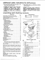
unpacking
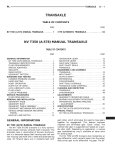
General Safety Instructions for Power Tools .........
Additional Safety Instructions for Drill Presses .......
Unpacking and Checking Contents .................
Table of Loose Parts ............................
Motor Specifications and Electrical Requirements
.....
Assembly
....................................
Installing the Chuck ..........................
Installing Feed Handles ........................
Installing the Depth Stop ......................
Installing Motor Pulley ........................
Mounting the Motor .........................
Installing and Tensioning Belt ..................
Getting to Know Your Drill Press .................
Belt Tension Rod ...........................
Drilling Speed ..............................
On-Off Switch
.............................
Removing the Chuck
........................
Drilling to Depth
...........................
Basic Drill Press Operation ......................
Installing Drills .............................
Positioning Table and Workpiece
...............
Feeding ...................................
Adjustments
.................................
Depth Scale ...............................
Quill Return Spring .........................
Table and Head Lock Handles .................
Quill Bearing ...............................
Pinion Backlash
............................
Automatic Feed Return ......................
Maintenance .................................
Lubrication ..................................
Recommended Accessories ......................
Trouble Shooting
.............................
Repair Parts .................................
AND
Your Craftsman Drill
carton, lessmotor.
contents
and checking
CONTENTS
UNPACKING
WARNING:
DO
NOT
ALLOW
FAMILIARITY
(GAINED FROM FREQUENT USE OF YOUR DRILL
PRESS) TO BECOME COMMONPLACE.
ALWAYS
REMEMBER THAT A CARELESS FRACTION OF A
SECOND IS SUFFICIENT
TO iNFLiCT
SEVERE
INJURY.
CHECKING
TOOLS
Page
2
3
4
4
5
6
6
7
8
9
10
12
12
12
12
13
14
15
15
16
16
17
17
17
17
17
17
18
18
18
18
19
19
20
_;
Key
No.
1
2
3
4
5
6
CONTENTS
Press is shipped complete in one
Separate all parts from packing materials and check each
one with the "Table of Loose Parts" to make certain all
items are accounted for, before discarding any packing
material.
7
8
9
10
11
12
13
14
15
16
17
18
If any parts are missing, do not attempt
to assemble the
drill press, plug in the power cord or turn the switch on
until the missing parts are obtained
and installed correctly.
Remove
column.
remover.
the protective
oil that is applied to the table and
Use any ordinary household type grease and spot
CAUTION: Never use gasoline, naptha or similar highly
volatile solvents.
Apply a coat of automobile wax to the table.
Wipe all parts thoroughly with a clean dry cloth.
4
....
TABLE
NEEDED
_
7/16 Inch Wrench
-_
1/2 Inch Wrench
OF LOOSE PARTS
Item
Belt, V ...............................
Pulley, Motor (w!Set Screw) ..............
Knob ................................
Rod .................................
Mount, Motor
.........................
Chuck, Drill ...........................
Bag of Miscellaneous Small Parts, Pt. # 71177
Consisting of the Following:
Key, Drill Chuck .......................
Carriage Bolt (5/16-18 x 3/4) ..............
Washer (11/32)
........................
Nut, Hex (5/16-18)
.....................
Tie, Wire .............................
SetScrew Wrench (5/32 inch) .............
SetScrew Wrench (1/4 inch) ..............
Key, Switch ...........................
Nut, Stop .............................
Pointer, Depth Gage .....................
Shoe, Depth Gage ......................
Screw, Thumb
.........................
Qty.
1
1
3
3
1
1
1
4
4
6
1
1
1
2
1
1
1
1
motor
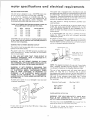
MOTOR
specifications
and
SPECIFICATIONS
This drill press is designed to use a 1725 RPM motor only.
Do not use any motor that runs faster than 1725 RPM.
It
is wired
for
operation
on 1t0-120
volts,
60 Hz.,
alternating
current.
IT MUST NOT BE CONVERTED
TO
OPERATE
ON
230
VOLTS,
EVEN
THOUGH
THE
RECOMMENDED
MOTORS
ARE DUAL VOLTAGE.
THESE
CRAFTSMAN
MOTORS HAVE
BEEN FOUND
BE ACCEPTABLE
FOR USE ON THIS TOOL
HP
1/3
1/2
1/2
3/4
RPM
1725
1725
1725
1725
VOLTS
!10-120
110-120
110-120
110-120
CATALOG
1250
1254
1255
1256
This machine
operator
from
TO POWER
SOURCE
must be grounded
electric shock.
NO,
adapter as shown
known ground.
and always
It is recommended
that
replace the TWO prong
THREE prong outlet.
while
in use to protect
GROUNDING
grounded
type
connect
the
grounding
you have a qualified
outlet
with a properly
lug to
electrician
grounded
LUG
ADAPTER
grounded
type
or Circuit-Saver
WARNING:
IF NOT
PROPERLY
GROUNDED
THIS
POWER TOOL CAN iNCUR
THE POTENTIAL
HAZARD
OF
ELECTRICAL
SHOCK,
PARTICULARLY
WHEN
USED
iN
DAMP
LOCATIONS,
IN
PROXIMITY
TO
PLUMBING.
IF
AN
ELECTRICAL
SHOCK
OCCURS
THERE
IS THE
POTENTIAL
OF
A SECONDARY
HAZARD
SUCH AS YOUR
HANDS CONTACTING
THE
CUTTING
TOOL.
or damaged
in any way, have
-PRONG
\
PLUG \
J, i% 'j._.__CONNECTED
TOA
KNO',"N
GROUND
Cord
OUTLET.
The motor
Wire Size A,W,G.
16
14
10
ROTATION
FOR YOUR
OWN
NOT
CONNECTED
WHEN
CHANGING
must rotate
shaft end to which
If it does
instructions
Length
Ft.
Ft.
Ft.
MOTOR
WARNING:
PLUG
tS
it has a plug
RECEPTACLE
Use only
3 wire extension
cords which
have 3 prong
grounding
type plugs and 3-pote receptacles
which accept
the tools plug.
CHECK
150 volts,
'
The use of any extension
cord will cause some loss of
power.
To
keep this
to a minimum
and to prevent
over-heating
and motor
burn-out,
use the table below to
determine
the minimum
wire size (A.W.G.) extension
cord.
GROUNDED
OUTLET
GROUNDING
PRONG
-7
I(
NOTE:
The adapter illustrated
is for use only if you already
have a properly
grounded
2-prong
receptacle,
Adapter
is
not allowed in Canada by the Canadian Electrical
Code.
Upto-lO0
100-200
200-400
@
Y......
_
Extension
3-PRONG
PLUG
If your unit is for use on less than
that looks like above.
3-conductor
An adapter as shown below is available for connecting
plugs
to 2-prong
receptacles.
The green grounding
Jug extending
from the adapter must be connected
to a permanent
ground
such as to a properly
grounded outlet box,
the
WARNING:
DO NOT PERMIT FINGERS TO TOUCH
THE TERMINALS
OF PLUGS WHEN INSTALLING
OR
REMOVING THE PLUG TO OR FROM THE OUTLET,
PROPERLY
a mating
If the outlet
you are planning
to use for this power toot is
of the two prong type DO NOT REMOVE
OR ALTER
THE
GROUNDING
PRONG
IN ANY
MANNER.
Use an
IF YOU ARE NOT SURE THAT YOUR OUTLET IS
PROPERLY
GROUNDED,
HAVE IT CHECKED BY A
QUALIFIED
ELECTRICIAN.
or cut,
This
plug requires
outlet as shown.
OUTLET
Plug power cord into a 110-120V
properly
outlet
protected
by a 15-amp. time delay
fuse or circuit breaker.
If power cora Js worn
it replaced immediately.
This power tool is equipped
with a 3-conductor
cord and
grounding
type plug which has a grounding
prong, approved
by Underwriters'
Laboratories
and the C_nadian Standards
Association:
The ground conductor
has a green jacket and is
attached to the tool housing at one end and to the ground
prong in the attachment
plug at the other end.
TO
CAUTION:
Do not use blower or washing machine motors
or any motor with an automatic reset overload protector as
their use may be hazardous.
CONNECTING
eJectricaJ requirements
MOTOR
CLOCKWISE
you will
SAFETY,
MAKE
SURE
TO
POWER
SOURCE
mount
ROTATION.
when
viewed
from
the
to
the
the pulley.
not, change
the direction
furnished
with the motor.
according
assembly
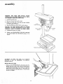
WARNING:
FOR YOUR
OWN SAFETY,
NEVER
CONNECT PLUG TO POWER SOURCE OUTLET UNTIL
ALL ASSEMBLY STEPS ARE COMPLETED.
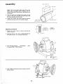
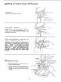
1. Unwind the power cord.
2. Make sure the quill lock handle is tight.
3.
4.
Stand on the left side of the drill pressand LOOSEN
the HEAD LOCK HANDLE.
HEAD
LOCK HAINDLE
Raise the HEAD about HALF WAY up the column.
CAUTION: THE HEAD WEIGHS ABOUT 70 POUNDS
DROPPING THE HEAD ACCIDENTLY
COULD CAUSE
PERSONAL INJURY OR DAMAGE THE DRILL PRESS.
5.
TIGHTEN the Head Lock Handle.
6.
Position the HEAD-SUPPORT COLLAR underneath
the head and tighten the TWO BOLTS using a 1/2 in.
wrench.
I
HEAD
COLLAR
PACKING
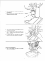
IN ORDER TO RAISE THE HEAD TO A HIGHER
POSITION, IT WILL BE NECESSARY TO INSTALL
SEVERAL PARTS.
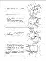
INSTALLING
THE CHUCK
Clean out the TAPERED
HOLE
spindle nose with a clean cloth.
foreign
piece of
prevent
the drill
SUPPORT
in the chuck; clean the
Make sure there are no
particles
sticking to the surfaces. The slightest
dirt on the spindle nose or in the chuck will
the chuck from seating properly.
This will cause
to "wobble."
6
BLOCK
QUILL L'OCK
HANDLE
SPINDLE
NOSE
2.
Apply a light film
the spindle nose.
of oil such as Sears household
3.
Place the chuck
on the spindle
nose
locking collar up as far as it will go.
and
oil to
screw
the
CHUCK
LOCKING
COLLAR
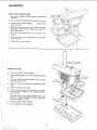
4.
Insert a piece of 5/16
the holes in the chuck
in. dia. STEEL
body.
ROD
in to one of
5.
Insert the CHUCK
KEY into one of the holes in the
collar
. . . TURN
IT IN THE DIRECTION
OF ARROW
UNTIL
IT IS TIGHT.
6.
To remove
chuck,
turn
the collar
in the opposite
direction
until the chuck is ejected from the spindle.
\
CHUCK KEY
!CHUCK
SLEEVE
5/16 IN. ROD
OR DRILL
BODY
iNSTALLING
1.
Screw
FEED
a FEED
HANDLES
HANDLE
holes in the hub, and tighten.
into
each
of the
threaded
FEED
HANDLE
assembly
FEED STOP
ROD
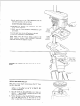
INSTALLING
THE DEPTH STOP
1. Screw the THUMB SCREW partways into the DEPTH
POINTER.
2.
Place the DEPTH POINTER SHOE inside the pointer.
3.
Loosen QUILL LOCK HANDLE
about two inches.
4.
5.
6.
7.
...
lower the quill
Slide the pointer and shoe onto the FEED STOP ROD
and tighten
the thumb screw. Make sure the pointer
is
positioned
as shown.
Screw the
stop rod.
FEED
Move the
the thumb
pointer
screvv.
Tighten
STOP NUT
onto
DEPTH
POINTER
the top
of the
feed
DEPTH
STOP
SHOE
SCREW
QUILL
LOCK
HANDLE
QU_LL
upwards
against
the nut
and tighten
LOCi< HANE_LE.
TABLE LOCK
HANDLE
(RIGHT HAND
SIDE)
RAISING THE HEAD
-1.
Z
Loosen
the TABLE
LOCK
HANDLE.
Place a piece of WOOD on the table.
block.
3.
Turn the CHUCK SLEEVE
way up inside the chuck.
4.
Raise the table
body.
5.
6.
until
Tighten
the Table
Locate
the
from the
your drill
two
until
the wood
8.
packing
QUILL LOCK
HANDLE
the jaws
block
touches
are all the
HEAD
LOCK HANDLE
the chuck
PIECE OF
WOOD
Lock
Handle.
clamps
and
paper tube when
press.
bolts
you
first
These parts make up the TABLE
Position the TABLE
SUPPORT
the table and tighten the bolts.
7.
USE THE
Loosen
the HEAD
LOCK HANDLE.
Loosen
the QUILL
LOCK
HAND
that
you
started
removed
unpacking
SUPPORT COLLAR.
COLLAR
underneath
TABLE SUPPORT
COLLAR
LE.
9.Gentlypushdownon theFEEDHANDLES
untilthe
headraises
upwards
asfarasit willgo.
DONOTRELEASE
FEEDHANDLE.
10,TIGHTENTHEHEADLOCKHANDLEANDTHE
QUILLLOCK
HANDLE.
11.HOLDontothe FeedHandle
andUNLOCK
thequill
lockhandle.
12.LetthequillreturntotheUPpositioninthehead,
13.TIGHTEN
THEQUILLLOCKHANDLE.
Repeatsteps3 thru 10until the headis raisedto the
desiredposition.PositionHEADSUPPORT
COLLAR
underneath
theheadandtighten
thebolts.
HEAD
LOCK
HANDLE
LOCK
HANDLE
HEAD EVEN
WITH
TOP
OF
CAUTION:
Do not raise
the
head
above
the top of
COLUMN
the
coBumn.
SUPPORT
COLLAR
INSTALLING
MOTOR PULLEY
When using a double
the 5/8 in. dia, shaft.
Using a
setscrew
KEYWAY
shaft
motor,
5/32
in. setscrew
in the pulley
so
(GROOVE).
remove
wrench,
that
it
the KEY
UNSCREW
is clear of
2,
Place the pulley
on the shaft. Make
EASILY
... don't FORCE it. Remove
pulley or on the shaft if any.
3_
Position
the pulley so that the KEYWAYS
and in the pulley
line up; and the small
pulley
is about 1/16 of an inch away from
from
the
the
sure it slips on
any burrs in the
in the shaft
end of the
the motor,
assembly
3/16 x 3/16
KEY
FLAT SPOT
NOTE:
shafts,
motor)
the flat
When using motors which have 1/2 in. dia.
place the adapter sleeve (furnished with the
on the shaft so that the slot in the sleeve is over
spot.
4.
Insert the shaft key (furnished with motor) into the
grooves in the shaft and pulley so that the end of the
key is even with the end of the shaft,
5,
Tighten the set screw. Use a pair of pliers on the short
end of the set screw wrench for increasedleverage.
I
i
I
I
1/2
IN.
MOTOR
MOUNTING
THE MOTOR
1.
Position the motor mount as shown and place the
motor on top of it.
2,
Find four 5/16 in.--18 x 3/4 in. CARRIAGE BOLTS,
flat washers and hex. nuts. among the loose parts.
3.
Insert the bolts as shown .,. install washers . .. screw
on nuts but DON'T TIGHTEN them.
3/4
DIA.
i
I
SLEEVE
SHAFT
IN.
BOLT
4.
Using a 5/32 inch set screw wrench unscrew the PIVOT
screws as shown.
Oplvosc :Ew
I0
5,
Remove
"'links".
the
belt
6.
Place motor on
into the holes.
guard
drill
by
press
"pushing
...
in"
screw the
on the
pivot
two
screws
NOTE: DO NOT SCREW THEM IN TOO TIGHT ...
EXCESSIVE
TIGHTNESS
COULD BEND THE
MOTOR MOUNT.
i
7.
Find two 5/16 in-18 hex. nuts among the loose parts
..,
screw them on to the pivot
screws ...
tighten
them with a 1/2 in. wrench while preventing
the pivot
screws from turning.
8.
Plug motor cord into outlet inside of dirll press.
9.
Find the plastic CORD TIE among
insert the pointed
end into the
mount.
10, Gather
CORD
up
TIE
the loose parts ...
hole in the motor
the slack in the motor
cord ... wrap the
around
it. •. insert one end of the TIE into
the hole in the other end.
cord to the motor mount.
Pull it tightly
to secure the
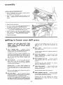
CAUTION: If you are using a DOUBLE SHAFT motor.
Make sure the SHAFT PROTECTOR is installed. NEVER
USE THE DRILL PRESS WITH THE UNUSED SHAFT
EXPOSED.
CORD TIE
assembJy
iNSTALLING
1.
Place a straightedge
framing
2.
AND TENSIONING
such as a piece of wood,
metal
or
square across the pulleys.
Move
the
LINE
...
wrench.
3.
BELT
motor
UPWARDS
until
tighten
the motor
mounting
the
pulleys
are IN
nuts with
a ½ in.
BELT TENSIONING
Place the belt on the pulleys.
ROD
MOTOR
4. Put a dab of grease such as Sears gear case lubricant on
the rubber tip of the BELT TENSIONING ROD.
5.
Loosen HEX HEAD SCREW with a 7/16 in. wrench
... position BELT TENSIONING ROD as shown.
6.
Push
while
the motor
to the right with moderate
pressure
pushing THE BELT
TENSIONING
rod against
the motor
7.
MOTOR
MOUNT
Replace
mount
...
TIGHTEN
the HEX SCREW.
_/-_"
/
the beltguard.
getting
to know
your
driJJ press
WARNING:
FOR YOUR
OWN
SAFETY
TURN
SWITCH
"OFF"
AND
REMOVE
PLUG
FROM
POWER
SOURCE
OUTLET
BEFORE
MAKING
ANY ADJUSTMENTS.
BELT
2
TENSION
ROD
...
maintains
is placed in the
speed will
then
minute).
4
constant
tension on the belt, TO RELEASE
belt tension
changing speeds, push the GRIP of the rod up.
for
To APPLY
belt tension,
PUSH the MOTOR
to
REAR while pulling DOWN on the GRIP of the
Belt should only be tight enough so that it does
slip.
If
belt
slips while
drilling,
readjust
tensioning
rod
the
rod.
not
belt
5
6
3
allowing
the quill
QUILL LOCK ... Holds the quill
point within its travel.
The
per
at any desired
HEAD
LOCK
HANDLE
column.
ALWAYS
have
operating
the drill press.
HEAD
SUPPORT
from
dropping
loosened.
...
it
COLLAR
when
the
locks the
locked
in
7
to
8
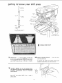
DRILLING SPEED ... Can be changed by placing
the belt in any of the STEPS (grooves) in the pulleys.
See Spindle Speed chart on right side of Head.
TABLELOCK
HANDLE
column.
operating
ALWAYS
have
the drill press.
ALWAYS
hold
TABLE
...
locks
it
locked
the table while
SUPPORT
COLLAR
head to the
place while
...
prevents
head
lock
ALWAYS
have the collar
LOCKED
against the UNDERSIDE
of the head.
Although
there
is a rubber
cushion
between
the
FEED STOP COLLAR
and the head, NEVER
let go
of the feed handles when you have finished drilling
a
hole.
while
step from
the top.
RPM (revolutions
To lock the quill requires only moderate pressure on
the lock handle.
FEED HANDLES
... are for moving the quill up or
down.
One or two
may be removed
if necessary
whenever the workpiece
is of such unusual shape that
it interferes
with the handles.
Hole on to the handle
return to the UP position.
FOURTH
be 2300
into
the
in
unlocking
...
the head
handle
is
table
place
to
the
while
it.
Prevents
from
accidently
dropping
all the way
when the table lock handle is loosened.
position
to the
the table
bottom
ALWAYS
have the collar
LOCKED
into position
approximately
34 in. from
the floor
for
average
To determine the approximate drilling speed, refer to
the table on the RIGHT side of the drill press head.
For example to drill a 5/8 inch hole in wood, the belt
drilling
12
operations.
tO
getting
kr ow
SPLINES
(GROOVES)
SPINDLE
QUILL
_
RACK
(TEETH)
CHUCK
__-_
KEY
QUILL
CHUCK
_
AND
INSIDE
SPINDLE
OF
ASSEMBLY
DRILL PRESS
SPINDLE SPEED CHART
9
10
CHUCK
KEY
...
is used to tighten
or loosen the
chuck. It has a spring loaded EJECTOR pin to "pop'"
it out of the chuck when you let go of it. When not in
use, ALWAYS
store the key in the hole in the table.
switch.
NOTE:
Key
is made
COLLAR
...
draws
the
of
t3
chuck
nose.
it prevents
the chuck
from
coming
loose
operation.
ALWAYS
have the collar tightened.
SWITCH for drill has locking feature.
THIS SHOULD PREVENT UNAUTHORIZED
AND
POSSIBLY
HAZARDOUS
USE BY CHILDREN
AND OTHERS.
KEY
into
plastic.
LOCKING
onto the spindle
11 "ON-OFF"
Insert
yellow
CHUCK
during
getting
to know
To turn drill
ON
Insert
under
switch
OFF
...
finger
TO turn drill
your
drill
press
..
lever and pull.
Push lever in.
In an emergency;
...thedrill
bit BINDS
...STALLS
..
STOPS
. .. or tends to tear the workpiece
loose . .. you
can QUICKLY
turn
the drill OFF by hitting
the switch
with the palm of your hand.
TO lock switch
in OFF position
one hand ... REMOVE
key with
... hold switch
other hand.
I
IN with
WARNING: FOR YOUR OWN SAFETY, ALWAYS LOCK
THE SWITCH "OFF" WHEN DRILL PRESS IS NOT IN
USE ...
REMOVE KEY AND KEEP IT IN A SAFE
PLACE ... ALSO ... IN THE EVENT OF A POWER
FAILURE
(ALL OF YOUR LIGHTS GO OUT) TURN
SWITCH OFF ... LOCK IT AND REMOVE THE KEY.
THIS WILL
PREVENT THE DRILL
PRESS FROM
STARTING
UP AGAIN WHEN THE POWER COMES
BACK ON.
J
HOLD
f
LOCKING
COLLAR
_2
REMOVING
CHUCK
THE CHUCK.
7.
Insert a piece of 5/16 in. dia. steel rod in one of
the holes in the chuck body.
2=
Insert the CHUCK KEY into one of the holes in
the collar ,., turn it in the direction of arrow
until LOOSE. Continue to turn it until the chuck
is released.
CHUCK
SLEEVE
KEY
I N. ROD
OR DRILL
\
14
_{_
!_
The DEPTH
POINTER
THUMBSCREW.
L FEED
STOP
NUT
is locked
limits
in place
the downward
with
movement
the quill at any desired point
within
its travel,
prevents the pointer
from moving upward.
DR! LLING
To drill
depth,
the
of
and
TO DEPTH
a BLIND
hole
(not
can be done two
depth
all the way through)
1.
Mark
the
workpiece.
2.
With the switch OFF bring the drill
or lips are even with the MARK
...
3.
Move
thumb
of
4.
Tighten
the STOP
5.
Unlock
the quill.
6.
Feed
the POINTER
screw.
the drill
to a given
ways.
the
hole
on
all the way
NUT against
into the
the
side
of
the
down until the TIP
LOCK the QUILL.
down
and tighten
J
the
the pointer.
workpiece
until
it is stopped
by
the pointer.
_5
ANOTHER
1.
With the switch
the TIP touches
•..
2.
WAY--
lock
OFF, bring the drill down until
the TOP of the WORKPIECE
the quill.
Set the POINTE
it and TIGHTEN
R to the desired DEPTH
... lock
the STOP NUT against it. For
example
...
if you want to drill a hole one inch
deep ... set the pointer
at the one inch mark in
the scale.
TIP TOUCHES
WORKPIEC_
'
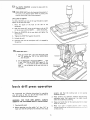
basic drill
I
press operation
We recommend
the following
instructions
your drill
press so that you get the best
minimize
the likelihood
of personal injury.
properly
excessive
for operating
results and to
3.
WARNING:
FOR
YOUR OWN SAFETY,
ALWAYS
OBSERVE THE FOLLOWING SAFETY PRECAUTIONS.
1.
Check
2.
Before operating,
turn the switch
"on"
then "off"
to
make sure that the cutting tool is centered in the chuck
spindle
speed
_5
and that
vibration.
the
cutting
tool
is not
causing
Never perform
any operation
freehand
(hand-hold{ng
workpiece
rather
than supporting
it on table) except
when wire brushing or polishing.
4.
Keep your hands clear of the
cutter or router bit).
5.
Make
sure quill
is locked
securely
when
_haping,
routing,
dovetailing,
wirebrushing,
polishing
s_ndh',,_ or
surface planing,
cutting
tool
(drill,
shaper
basic drill
INSTALLING
press
operation
DRILLS
Insert drill
GRIPPING
into
chuck
far enough
of the CHUCK JAWS ...
to obtain maximum
the jaws are appox. 1
in. long. When using a small drill do not insert it so far that
the jaws touch the flutes (spiral grooves) of the drill.
Make sure that
tightening
Tighten
drilling.
the
the chuck
the drill
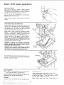
POSITIONING
drill
is CENTERED
with
sufficiently,
TABLE
in the chuck
before
the key.
so that
AND
it does not SLIP while
WORKPIECE
Lock the table to the column in a position so that the tip of
the drill is just a little above the top of the workpiece.
It is
not
necessary
to
reposition
the
TABLE
SUPPORT
COLLAR
each time you reposition
the table. Always keep
the collar locked about 34 in. from the floor.
Always
place a piece of
plywood
...)
on the table
will prevent "splintering"
underside of the workpiece
BACK-UP
MATERIAL
(wood,
underneath
the workpiece.
This
or making a heavy burr on the
as the drill breaks through.
QUILLHAN
LO
Position
workpiece
to butt against the column
whenever
possible - if it is too short, clamp solidly
to the Table this is to prevent the drill bit from grabbing the work from
your hands, which could result in personal injury. A drill
press vise must be fastened to the table.
_
VCORKPIECE
CAUTION:
To prevent
the workpiece
or the back-up
material from being torn from your hand while drilling,
position them against the left side of the column. Failure to
do this could result in personal injury.
CAUTION:
If the workpiece or the back-up material
are
not long enough to reach the column, CLAMP them to the
table. Failure to do this could result in personal injury.
For small pieces that cannot be clamped to the table, use a
drill
press vise (Optional
accessory),
The vise must
be
clamped or bolted to the table.
WORKPIECE
"\
\
DRILL PRESS
VISE
HOLE LOCATION
Make a DENT in the workpiece
where you want
... using a CENTER
PUNCH or a SHARP NAI L.
Before turning
the switch ON, bring the drill
workpiece
lining it up with the hole location.
allow
the hole
down
to
the drill
Feeding
Feeding
the belt
the
from
to cut.
TOO SLOWLY
might cause the drill to burn
..,
TOO RAPIDLY
might stop the motor
.., cause
or drill to SLIP
... tear the workpiece
LOOSE
your
hand
or BREAK
the drill
bit.
FEEDING
When
Pull
down
on the feed
handles with
only enough
effort
to
16
drilling
metal
use
Sears
Thread-cutting
oil
diustments
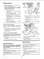
WARNeNG: FOR YOUR OWN SAFETY TURN SWITCH
"OFF"
AND REMOVE PLUG FROM POWER SOURCE
OUTLET BEFORE MAKING ANY ADJUSTMENTS.
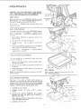
DEPTH
SCALE
When the
SURFACE
quill
is in the UPPERMOST
position,
the top
OF THE FEED STOP POINTER
should be in
line with
"0"
If
not
it
is
reposition
QUILL
graduation
...
on the DEPTH
LOOSEN
both
SCALE.
mounting
screws
and
the scale.
RETURN
SPRING
If the quill
does not return
to its UPPERMOST
position
when the quill !ock is UNLOCKED
,..
or if the return
action
is SLUGGISH
... the SPRING TENSION
must be
increased.
1.
Move
DEPTH
POINTER
lock it in place.
2.
Lock
3.
GRASP
to turn.
4.
Rotate hub TOWARD
you about 1/4 turn and PUSH
back in place. This will WIND UP the spring.
5.
Unlock
quill
°.. check tension
repeat steps 2, 3, 4, and 5.
TABLE
The
the quill
lock
t.
HEAD
handles
convenient
uppermost
in the uppermost
the HUB
AND
to
...
pull
LOCK
can
position
U
QUILL
RETURN SPRING
and
position.
it straight
HUB
out until
...
if more
it is free
t
it
,
TABLE LOCK
HANDLE
is required,
FEED
HANDLE
HANDLES
be
adjusted
to
make
them
more
to operate.
Make sure the support
the table or the head.
lock
collar
is locked
in position
below
TABLE
2.
Unscrew
the
of the hole.
handle
3.
Rotate the barrel lock
screw in the handle.
and push the barrel
lock
out
it in the hole
and
LOCK
HANDLE
BARREL LOCK
NOTE:
The HEADLOCK
side of the head.
QUILL
BEARING
180 ° , replace
HANDLE
is located
on the
LEFT
or SPREAD
apart
1.
TIGHTEN
quill
2.
LOOSEN
wrench.
setscrew
3,
Rotating
direction
AWAY
the
will
from
by adjusting
LOOSEN
to section "Getting
To Know
TENSIONING
ROD.
Your
Driit
Press"
three
QUILL
LOCK
HANDLE
screws.
lock handle.
"A"
eccentric
move
the
using
a
5/32
in.
SPLIT
setscrew
BUSHING
"B"
in either
pinion
shaft
TOWARD
or
the quill.
quill
lock
ECCENTRIC
BUSHING
FIBER WASHER
With a large pair of pliers, rotate
shaft moves AWAY from quill.
4.
TENSION
Refer
BELT
. . .
ADJUSTMENT
The
front
of the
head is "Split"
which
permits
an
adjustment
to be made as the quill and the quill bearing
surfaces inside of the head become worn after an extended
period
of use. The front
of the head can be SQUEEZED
together
BELT
SET SCREW "A"
bushing
so that
pinion
handte.
!7
"Bi'
adiustments
5.
LOOSEN
all three screws "C",
using 1/4 in. setscrew wrench.
"D",
and "E'"
NOTE:
TIGHTENING
BOTH SCREWS
SQUEEZES
HEAD
TOGETHER
...
SCREW "'D" SPREADS
IT APART.
a.
IF QUILL
four
turns
COLUMN
LOCK
"C'" AND "E'"
TIGHTENING
ISTOOTIGHT
SCREW
(1) TIGHTEN
screw "D"
up and down.
(2)
until
is free to move
Extend
quill
halfway
down
...
screw "E" until quill is LOCKED.
(3) Carefully
LOOSEN
screw "E"
(4) TIGHTEN
screw "'C'"
does not lock the quill
and down freely.
(5) Re-adjust
pinion
Adjustment).
b.
quill
IF QUILL
ISTOO
TIGHTEN
until
quill
SCREW "E"
I
is free.
only enough
so that it
... quill must move up
backlash
(See Pinion
(2) Carefully
LOOSEN
screw "E"
(3) TIGHTEN
screw
does not lock the
and down freely.
Backlash
"C"
quill
(4) Screw in remaining
tighten it lightly.
LOOSE
(1) Extend
quill
halfway
down
screw "'E" until quill is locked.
...
TIGHTEN
(5)
Re-adjust
pinion
until
quill
is free,
only enough
so that it
... quill must move up
screw
"D"
backlash
all the
way
(See Pinion
,..
Backlash
Adjustment).
PINION BACKLASH ADJUSTMENT
Rotating the ECCENTRIC BUSHING in either direction
will move the pinion shaft TOWARD or AWAY from the
quill.
1.
LOOSEN setscrew "A "° using 5/32 in. setscrew wrench.
2.
With a large pair of pliers, rotate bushing so that pinion
revolves freely with no "clicking" sound.
3.
TIGHTEN
AUTOMATIC
IC BUSHI NG
setscrew.
FEED RETURN ADJUSTMENT
If, after adjusting quill bearing and pinion backlash, the
automatic feed return fails to return the quill to the top of
its stroke, or if the action is sluggish,the feed return can be
adjusted as follows:
1.
Lock the quill
lock handle.
2.
Pull hub straight
3.
Rotate counterclockwise
push it back in place.
4.
Loosen quill and check tension.
repeat steps 2 & 3 above.
at the top of its stroke with the quill
out until
you can rotate
it.
approximately
1/2
turn
...
If more is required,
lubrication
maintenance
All of the BALL BEARINGS
are packed with
factory. They require no further
lubrication.
WARNING:
FOR YOUR OWN SAFETY,
TURN
SWITCH
"OFF"
AND
REMOVE
PLUG
FROM POWER SOURCE
OUTLET
BEFORE
MAINTAINING
OR LUBRICATING
YOUR
DRILL
PRESS.
blow
out any dust that
A coat
of
automobile-type
column
will help to keep the surfaces
wax
may
accumulate
applied
to
the
follow
inside
table
and
clean.
If the power cord is worn or cut, or damaged
have it replaced immediately.
maintenance,
the SPLINES
on the quill).
(grooves)in
the spindle
USE Sears Gear Case Lubricant.
Frequently
the motor.
For motor
motor.
Periodically
lubricate
and the RACK (teeth
grease at the
instructions
in any way,
furnished
with
1.
Lower quill
the quill.
2.
Use a small stick of wood and apply lubricant
the inside of the hole in the spindle pulley.
3.
Apply
below
For motors
motor.
18
and
spindle
all
lubricant
to RACK
drill press head.
lubrication,
follow
the
way
(teeth)
down
on quill
instructions
. ..
LOCK
around
extending
furnished
with
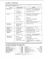
trouble
shooting
WARNING:
FOR YOUR OWN SAFETY,
TURN
OUTLET
BEFORE
TROUBLE
SHOOTaNG.
"OFF"
AND
ALWAYS
REMOVE
Operation
Drill Burns.
I
FROM
POWER
1. incorrect belt tension
1. Adjust tension. See section
Your Drill Press"...BELT
2. Dry Spindle
2. Lubricate
3. Loose spindle pulley
or motor pulley.
3. Tighten
1. Incorrect
1.
speed
spindle.
setscrews
"Getting
To Know
TENSIONING
ROD.
See "Lubrication"
section.
in pulleys.
Change speed. See section "Getting
To Know
Your Drill Press"...
DRILLING
SPEED.
2. Chips not coming out
of hole.
2. Retract
3. Dull Drill
3. Reshapen
4. Feeding too slow,
4. Feed fast enough...allow
drill
to cut.
5, Not lubricated.
5. Lubricate drill. See "Basic
Operation"
section.
Dritl
Press
6. Drill
6. Check
running
1.
backwards.
t
Hard grain in wood
lengths of cutting
lips and/or angles
not equal.
SOURCE
REMEDY
drill
frequently
motor
1. Resharpen
or
to clear chips.
drill.
rotation.
and Electrical
Drill leads off...
hole not round.
PLUG
PROBABLE CAUSE
TROUBLE
Noisy
SWITCH
See "Motor
Requirements"
drill
Specifications
section.
correctly.
Wood splinters on
underside.
1. No "back-up material"
under workpiece.
1. Use "back-up
material"...See
Press Operation"
section,
Basic Drill
Workpiece torn
loose from hand.
1. Not supported or
clamped properly.
!, Support workpiece
or clamp it...See-"Basic
Drill Press Operation"
section.
Drill Binds in
workpiece.
1. Workpiece
pinching
or excessive feed
1. Support workpiece
or clamp it...See
Drill Press Operation"
section.
drill
"Basic
pressure.
Excessive drill
runout or wobble.
2. Improper belt tension,
2. Adjust tension,..See
section "Getting
to Know
Your Drill Press"...BELT
TENSION
ROD.
1, Bent drill.
1. Use a straight
2, Worn
spindte
2. Replace bearings.
bearings.
3. Install drill properly...See
Press Operation"
section.
3. Drill not properly
installed in chuck.
4. Chuck
'
I
I1'
recommended
r
not properly
''
I
drill.
"Basic
Drill
4. Install chuck properly...refer
to "Unpacking
and Assembly Instructions"...INSTALLING
CHUCK.
installed.
THE
iii
accessories
Drills, Shaper Cutters, Router Bits
.........
Rotary Planer
.............................
Mortising
Chisel Housing
....................
Hollow Chisels and Mortising
Bits ..........
Dovetailing
Attachment
.....................
Shaper Fence Attachment
...................
Hold-Down
and Guide
......................
Drill Press Vises
.......................
Rotary Table
.............................
Tilt Table
................................
Cotlet Chuck .............................
See Catalog
9-2745
9-2465
See Catalog
9- 2462
9-2487
9-2457
See Catalog
9-2495
Shaper Cutter Adapter
.....................
Sanding Drum ......................
Hole Saws up to 21/= in. dia ...............
Wire Wheels up to 4 in, dia, max ...........
Buffing
Wheels up to 4 in. dia. max .........
Polishing
Wheel, 1W'x
1 tn ..................
Column Collar
............................
The recommended
accessories listed
were available at the time this manual
79
here are current
was pr;nted.
and
9-243g
9-24672
9-2497
9-24832
- 9-2498
See Catalog
See Catalog
See Catalog
9-64991
9-2438
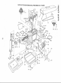
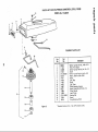
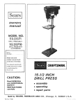
PARTS LIST FOR CRAFTSMAN
DRILL
PRESS MODEL
NO. 113.2461!
(!)
T_IO
1
SEE FIGURE
8
2
Q
13
14
mmll €)
11 12
2O
SEE FIGURE
"0
2
I
J
ALL WIRES
TO
i
SNAP
INTO WIRE SADDLE
3
_\
I--.83
_.
81
82
22
27
30
68
64
//_
80
79
65
6O
36
21
15
i_
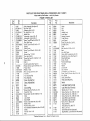
PARTS LIST FOR CRAFTSMAN
DRILL PRESS MODEL NO, 113.24611
Always order by Part Number - not by Key Number
FIGURE
PARTS LIST
Key
No.
1
2
3
4
5
6
7
8
9
10
11
12
13
14
15
16
17
18
19
20
21
22
23
24
25
26
27
78
f
Part
No.
70197
STD 541110
71046
STD 571812
71163
STD 551210
STD 551208
STD 600605
71092
STD 610805
71170
37818
STD 601103
71056
37837
STD 541031
STD 503105
71164
71138
9411963
71065
STD 551031
STD 533107
71165
71152
71153
79
:0
60226
71151
60311
7
71166
2
3
4
5
6
7
8
9
0
1
2
3
4
145372
71106
STD 523115
71050
38626
71098
STD 600603
38452
60193
71108
71109
60197
71139
Key
No,
Description
Pulley Assembly (See figure 2)
*Nut, Hex 10-32
Connector, Wire 14-18
*Pin, Rol! 3/16 x 1-1/4
Saddle, Wire
*Lockwasher, Internal No. 10
Lockwasher, Internal No. 8
*Screw, Type 23 Pan Hd. 6-32 x 1/2
Plate, Rear Cover
*Screw, Type A Pan SI. No. 8 x 1/2
Bracket
Relief, Strain
*Screw, Type 23 Pan SI. 10-32 x 3/8
Outlet
Wrench, Hex "L" 5/32
*Nut, Hex 5/16-18
*Screw, Set Cone Pt., 5/16-18 x 1-!/4
Mount, Motor
Belt, V
Guard Assembly (See Figure 2)
*Screw, Set Soc. Cup Pt. 5/16-t8 x 1/2
Pulley, Motor
*Washer, 11/32
*Bolt, Carriage, 5/16-18 x 3/4
Tie, Wire
Tip, Adjusting Rod
Rod, Adjusting
45
46
47
48
49
5O
51
52
53
54
55
56
57
58
59
6O
61
62
63
64
65
66
67
68
69
7O
71
Screw, Adjusting Rod
Clamp,AdjustingRod
Grip
Cord with Plug
*Screw, Drive Rd. Hd. No. 4 x 1/4
Panel, R.H. Trim
*Screw, Mach. Hex Hd. 5/16-18 x 1-1/2
Collar
Lock, Barrel
Scale, Depth
*Screw, Type 23 Pan Hd. 6-32 x 3/8
Washer, Fiber
*Pin, Roll 3/16 x 2-1/4
Hub Assembly (Includes Key Nos. 42 & 43)
Spring
Pin, Roll 1/4 x 1-1/8
Rod
*Standard
Hardware
Item
-
Ma,
Part
No.
38546
71110
60263
60265
38627
71111
71136
38631
138666
71113
STD 525025
71101
71157
38623
71158
71149
60191
71140
71082
71161
38632
63467
318595
448003
60256
71156
71119
Description
Knob
Cap
Grip
Handle, Lock
Lock, Barrel
Bearing, Eccentric
Tube, Column
Lock, Barrel
*Screw, Set, Hex Soc., Cup Pt,,
5/16-18 x 5/16
Table
Bolt, Hex Hd. 1/2-13 x 2-1/2
Base
Key, Drill Chuck
Chuck, Drill (Includes Key No. 57)
Spindle Ass'y, Stop (See Figure 3)
Shoe, Depth Gage
Screw, Thumb
Pointer, Depth Gage
Nut, Stop
Handle
Lock, Barrel
Cap, Insu!ator
Lockwasher, Int. C'Sink No. 8
Screw, Type 23, Pan Hd, S}ot, 6-32 x 3/8
Key, Switch
Cover, Switch Plate
Plate, Switch Mounting
72
73
60267
60275
Switch
74
60274
Lead, White (Small Terminal}
75
76
77
78
79
8O
81
82
30505
9421626
138222
138225
60276
60277
132124
71121
83
71107
71176
71177
be Purchased
Locally,
Lead,Black(SmallTerminal)
Wrench, Hex "L" (1/4)
Screw, Hex Soc. Hd., 5/16-18 x
Screw, Hex Soc. Hd., 5/16-18 x
Screw, Hex Soc. Hal., 5/16.18 x
Lead, White (Large Terminal)
Lead, Black (Large Terminal)
*Screw Fil. Hd. 10-32 x 3/4
Head, Drill Press
(Includes Key Nos. 8! & 77)
Panel, L.H. Trim
Owners Manual (Not Illustrated)
Bag Assembly, Loose Parts (Not
I-I/2
1
1-3/4
Illustrated)
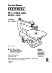
PARTS LIST FOR CRAFTSMAN
S
MODEL
COMMERCIAL
DRILL
"=!
PRESS
No. 113.24611
"O
Q
Bm=e
=O
Q
..
t_
__
Key
Part
No.
No. FIGURE
Description
2 PARTS LIST
,_, r =
*Screw, Type
23, Pan Hd., 4-40 x 3/16
Panel, Front Guard
Screw, Type B, Flat Hd., No. 10× 1/2
Guard
*Screw, Type B, Pan Hd., No. 8 x 3/4
Washer, 13/64 x 9/16 x 3/G4
Clamp
71128
12
\
144987
4
71069
5
6
STD 610807
60158
7
8
71071
71070
1_]
71072
Link, Front
11
71097
12
60227
71162
13
14
71089
71090
15---"--_
15
16
STD 315253
71091
Pulley Assembly,
Spindle
Screw, Nylock Set, 5/16-18
Pulley, Spindle
Insert, Pulley
Bearing, Ball
Spacer
Ring, Retaining,
15/16
16.------_
17
18414
13
14
11_
*Standard
T5
__._.
_
Figure
2
Hardware
Link, Rear
Clamp
Item
-
May be Purchased
Locally.
x 1/2
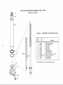
PARTS LIST FOR CRAFTSMAN
COMMERCIAL
DRILL
PRESS
MODEL No. 113.24611
/
/
/
/
,/
/
FIGURE 3 -- 71158 SPINDLE
ASM. STOP PARTS LIST
/
1,
/
Key
No.
/
/
/
/
Description
/
/
t
/
Part
No.
/
10---_
11
1
2
3
4
5
6
7
8
9
10
11
*Standard
71158
60278
71127
71159
60199
60200
71126
71124
138222
STD 541237
71078
71160
Hardware
Spindle Assembly, Stop
Ring, Retaining, 5/8
Bearing, Ball
Tube, Quill
Gasket, Quill
Ring, Retaining
Nut, Spindle Bearing
Collar, Feed Stop
*Screw, Hex Soc.Cap, 5/16-18 x 1
*Nut, Hex, Jam., 3/8-18
Rod, Depth Stop
Spindle Assembly
Item
-
May be Purchased
Locally:
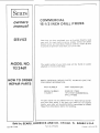
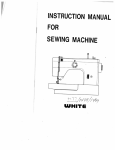
Sears
COMMERCIAL
15-1/2 INCH DRILL
SERVICE
MODEL NO.
113.24611
HOW' TO ORDER
REPAIR PARTS
PRESS
Now that you have purchased
your drill
press,
should
a need
ever exist for repair parts or service, simply
contact
any Sears
Service Center and most Sears, Roebuck
and Co. stores. Be sure
to provide all pertinent
facts when you call or visit.
The model number
of your drill
attached to the rear of the head.
WHEN ORDERING
REPAIR
FOLLOWING
INFORMATION
press will
PARTS,
be
found
ALWAYS
on a plate
GIVE
PART NUMBER
PART DESCRIPTION
MODEL NUMBER
113.24611
NAME OF ITEM
15-1/2 INCH COMMERCIAL
DRILL PRESS
THE
All parts listed may be ordered
from any Sears Service Center
and most Sears stores. If the parts you need
are not stocked
locally,
your order will be electronically
transmitted
to a Sears
Repair Parts Distribution
Center for handling.
Sold
Part No. 71176
by SEARS,
ROEBUCK
AND
CO.,
Form No. SP4! 29-5
Chicago,
tL.
60684
U.S.A.
Printed in U.S.A. 4/78