1
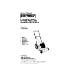
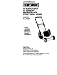
OWNER'S
MANUAL
MODELNO.
917.372270
CRRFTSMRN
4.0 RESERVE
POWER
22" REARBAGGER
POWERPROPELLED
ROTARYLAWNMOWER
Caution:
Readand Follow
all Safety Rules
and Instruchons
BeforeOperating
ThisEquipment
Assembly
Operation
Maintenance
ServiceandAdjustment
RepairParts
i
i
i
i i illll,llll
SEARS,ROEBUCK
AND Co., Chicago, IL.
i i llll
60684 U.S.A.
SAFETY
RULES
CAUTION:
ALWAYS
DISCONNECT
SPARK PLUG WIRE AND
PLACE WIRE
WHERE
IT CANNOT
CONTACT TRANSPORTING,
SPARK PLUG TO PREVENT
ACCIDENTAL
STARTING WHEN
SETTING-UP,
ADJUSTING
OR MAKING
REPAIRS TO YOUR MOWER_
IMPORTANT
FEDERAL REGULATIONS REQUIRE OPERATOR PRESENCE BLADE STOP CONTROLS TO MINIMIZE THE
RISK OF BLADE CONTACT INJURY, YOUR MOWER IS EQUIPPED WITH SUCH CONTROLS, DO NOT
ATTEMPT TO DEFEAT THE FUNCTION
OF THE OPERATOR PRESENCE CONTROL UNDER ANY
CIRCUMSTANCES,
•
•
BE CAREFUL-WHEN THE ENGINE IS RUNNING THE BLADE iS TURNING,,
Please road your owner's manual Only allow
persons who know the safety rules to use your
•
mower,
"
Q
•
•
•
o
"
o
°
o
°
_,
DO NOT tie the operator presence control bar
to the handle° Control must be free to permit
brake engagement when handles and control
are released.
DO NOT aliow children to use your mower.
Check your mower over before each use.
Tighten any loose bolts, nuts, etc.
Remove all sticks,stones, wires, cans, boards,
etc from area to be mowed. These objects can
be thrown by the blade.
DO NOT allow children, bystanders or pets in
the area while mowing°
Always wear shoes when mowing. DO NOT
operate mower when barefoot or wearing
open sandals,
Always wear safety glasses or eye shields
before starting your lawn mower and while
mowing.
Always shut off engine before trying to adjust
wheeiheights.
When engine, is running, DO NOT put hands
or feet und_,_wer
or m the discharge chute,
nor make _in_!_'diustments
Stay clear ot'_scharc_e openma at all hines.
Do not fill gas tank w'O_enengine _srunning,
when indoors or wh_ _QrLcline is hot, Allow
engine to cool for several _n'lnutesbefore fllling gas tank,. Clean off aB_ spilled gasoline
before starting engine.
'
Mow only in goodlight.
Always stop blade When not cutting grass or
when crossing gravel drive, sidewalk, or
roadway
•
o
•
'_
o
o
'_
DO NOT continue to run your mower if you
hit a foreign obiecL Stop the engine, disconnect the spark plug wire from the spark plug,
inspect the mower for damage and make
repairs as required,
DO NOT use a damaged mower. Always have
damage repaired before mowing,
DO NOT run your mower if it vibrates too
much, Stop engine and make repalrs,. Vibration is an indication of damage,
Never use your mower wilhout proper guards
or deflectors in place
,_,_
Always mow across c_sto_e or!inclined area.
DO NOT mow up or down a _lo_e._or inclined
area.
..
DO NOT mow n wet grass Be ca'r'e_u of
footing when mowing m wet grass,, use _t_ges,_
with good tracfion_
_,'
DO NOT run with the mower°
_
DO NOT run your mower indoors. Exhaust
gases are deadly pobon_.
Always disconnect the spark plug wire from
spark plug to prevent accidental starting when
transporting or storing your mower after the
mowing
•
•
"
•
season.
DO NOT attempt to raise engine speed above
factory settings_ Engine damage or personal
injury may result.
If a grass catcher is used on your mower, check
_he catcher often for damage or deterioration.
tt will wear through normal use. Use only a
recommended replacement catcher_
Always stop blade to remove or install catcher.
DO NOT slore your mower or gasoline where
fumes may reach an open flame and cause a
fire..
DRAIN THE GASOLINE from your mower
before transporting your mower inside your car
or other vehicle.
LOOKFORTHISSYMBOLTO POINTOUTIMPORTANTSAFETY
PRECAUTIONS°
IT MEANS--ATTENTION!H BECOMEALERTflfYOUR SAFETYIS
INVOLVED.
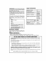
PRODUCT
SPECIFICATIONS
COHGP,
ATUIA110HS
on your purchase of a Sears Craftsman Lawn Mower. It has been designed, engineered
and manufactured to give you the best possible
dependability and performance.
Should you experience any problem you cannoteasb
ly remedy, piease contact your nearest Sears Service CenterlDepartment, We have competent, welb
trained technicians and the proper tools to service
or repair this unit.
40
DISPLACEMENT:
9,98 cu. in.
GASOLINE
) O quart
_umeaaea_
OIL (2t
CAPACITY:
oz.. Capacity):
SAE 30W
(SAElOW 30)
Please read and retain this manual, The instructions
wilt enable you to assemble and maintain your
mower properly. Always observe the "SAFETY
RULES".
,, ,ll
RESERVE POWER:
SPARK
PLUG (GAP
VALVE
CLEARANCE:
030
in):
Champion
RJ 19-LM or
(Seers 7133312 or
STD 36145g)
,Ll,l,,
MODEL
NUMBER 917.372270
SERIAL
NUMBER
Intake:
Exhaust:
008
,008
in
in.
_h
SOLID STATE
AIR GAP:
DATE OF
PURCHASE,
BLADE
NUT
tGNITtON
TORQUE:
,0125
in.
70-75
ft.-lbs.
THE MODEL AND SERIAL NUMBERS WILL BE
FOUND ON A DECAL ATTACHED TO THE REAR
OF THE MOWER HOUSING
YOU SHOULD RECORD BOTH SERIAL NUMBER
AND DATE OF PURCHASE AND KEEP IN A SAFE
PLACE FOR FUTURE REFERENCE,
MAINTENANCEAGREEMENT
A Sears Maintenance
Agreement
is available on this
product,
Contact
your
nearest
Sears
store for
details.
CUSTOMERRESPONSIBILITIES
•
,,
Road and observe the safety rules_
Fallow a regular schedule in maintaining,
FoItow the instructbns
under "Maintenance"
caring for and using your mower.
and "Storage"
sections of this Owner's
Manuel
ONE
YEAR
UMnED
WARRANTY
ONCRAFTSMAN
POWER
MOWER ........
For one year from the date of purchase, when this Craftsman Lawn Mower is maintained, lubricated and tunedrup.
according to the instructions in the owner's menuat, Sears wilt repair, free of charge, any defect in material
and workmanship.
If ehls Craftsman Lawn Mower is used for commerclal
days from the date of purchase.
This warranty
or rental purposes,
this warranty
applies
for onty 90
does not cover:
Expendable items which become worn during normal use, suchas rotary
botts, air cleaners and spark plug
mower blades, btade adapters,.
Repairs necessary because of aperalor abuse or negligence, including bent crankshafts end the failure Io
maintain the equ=pment according to the instructions contained in the owner's manua_
WARRANTY
SERVICE IS AVAILABLE
BY RETURNING THE CRAFTSMAN
POWER MOWER
NEAREST SEARS SERVICE CENTER/DEPARTMENT
IN THE UNITED STATES. THIS WARRANTY
ONLY WHILE THIS PRODUCT IS IN USE iN THE UNITED STATES
This warranly
to state.
TO THE
APPLIES
gives you specific legal rights, and you may also have olher rights which may vary from stale
SEARS, ROEBUCK AND
CO. Department
6981731A
3
Sears Tower,
Chicago,
lil. 60684
TABLE
OF CONTENTS
SAFETY RULE ............
PRODUCT SPECIFICATIONS.
,
CUSTOMER RESPONSIBILITIES
WARRANTY
........
TABLE OF CONTENTS
INDEX ...............
MOWER ACCESSORIES
ASSEMBLY.
OPERATION
2
3
3
. 3
4
4
5
6
7,8,9
MAINTENANCE
STORAGE ..............
SERVICE AND ADJUSTMENT
TROUBLE SHOOTING
.
REPAIR PARTS-MOWER
REPAIR PARTS.ENGINE
.....
SERVICE RECOMMENDATIONS
PARTS ORDERING/SERVICE
6
P
....
10,t 1,12
t5
t3,14
_7
18-2!
22.23
16
24,25
INDEX
A
Adjustments:
Carburetor
Engine Speed
Handle Height
Height of Cut
Wheel Adiusters
Air FiJter:
Cleaning
Paper Cartridge
Rep|acement
Assembly:
Handie
Accessarles
Gasoline
13
13
14
8
8
t2
10
10
3
Handb:
Adtustment
Assembly
Bracket
Knob
, .
Height, Culling
t4
•6
')4
7
8
6
5
4
Bfade:
Rep|acement
Sharpening
Controls:
Engine Coelrol
,
. ,
Operator
Presence Control Bar
Speed Selector , ..
Customer Responsibilities
Cuffing Levels
Engine:
Control
10
10
7 8
7
78
3
8
7.8
Oil Cap
Oil Change
Oil Level
.7
11
g
Off Type
Sterling
Storage
8
,g
15
Filter, Air
Fuel:
Type
Storage
12
,8
15
L
Lubrication:
Engine
Front Wheel Adjuster
Maintenance:
Agreement
Air Filter .
Air F'iltor Paper Cartridge
Blade Care/Rep|acement
Engine
Gross Catcher
L_tbrication
Spark Plugs
Mowing Tips
O_l:
Cold Wealher
Conditions
Engine
Storage
Operation:
OpBrat_ng Mower
Speed:
Slatting the Engine
.
Stopping Your Lawn Mower
Operafor
Presence Control
Options:
Attachments
4
16
8
,3
t2
'_2
t0
11
6,8
16
12
9
Parts
Primer
RepairtReplacament
Parts
Respansib_fflies, Customer
7,&g
9
9
7
5
20
3
S
Safety Rules
Service and Adiustmenls:
B_ode
Carburetor
Cutting Level
Engine
HandIe
Service Recommenciation
Spark Plugs
Specifications
Speed Control:
Engine
Starting the Engine:
Starter Rope
Slopping the Mower
Storage
1o
t3
8
,gg
6,14
16
12
3
g
,7
t5
T
Table of Contents ,
Trouble Shooting Chari
Warranty
Wheels:
Wheel Adjusters
9
11
15
"_B-2t
8
.4
]7
3
B
i1,,
i
i
,11,,11111
i
i,ii
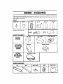
MOWER ACCESSORIES
..........................
, 11n1,_111111,
i
i,i i,
iiii
i1,, i
i , ,i
These accessories were available when the mower was purchased They, ere also available at most Sears retait
ouflels, catalog and service centers Mast Sears stores can order repair parts for you, when you provide th_
model number of your mower,
ENGINE
, ,11 i,i
SPARKPLUG
_11
i_11,1
MUFFLER
AIR FILTER
©
0
Hill
STABILIZER
2
i
I
,i
mower
iii
iii,
ENGINEOIL
GASCAN
i
iiiii
III
is an electric start
J CHARGER
i BATTERY
MOWER PERFORMANCE
ii ii ii ii
iiii,
ii1,,i
DUSTSHIELD
,
,i iii1,11111,
LEAFCATCHER
REARBAG
OPTIONAL
REPLACEMENT
BAG FOR REAR
DISCHARGE
MOWERS
I
i .....................
CLIPPINGDEFLECTOR
PERMANEX
CATCHER
FABRICBAG
, H,H,, H ,,,',,"t,"
OPTIONAL
CATCHER
FOR
SIDEDISCHARGE
MOWER
SIDEDISCHARGE
CATCHER
MOWER MAINTENANCE
,11
BELT
BLADE
WHEELS
BLADEADAPTER
,,,,
i
,
,L,
,
,
MOWERCOVER
,,,,,, ,,,,
,ip i,, , i, ii
, i
ASSEMBLY
i
,
_ ,,
i
i
Your lawn mower has been completely assembled
at the factory except for the grass catcher top and
the grass catcher bottom,
OPERATOff
Pt_SEtVC_
TO REMOVEMOWERFROMCARTON
i
*
*
grass catcher, catcher frame, hardware pack,
elc,).
Remove loose parts if included with mower, (Le,
Cut down corners on one end of carton and lay
end down flat.
Remove packing material
Roll mower out of carton and check carton
thoroughly for loose parts.
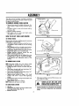
flOW TO SET-UPYOURLAWNMOWER
10 UNFOLD HANDLE
Remove tape and paper holding aperator presence
control bar to upper handb.
. Hold down operator presence control bar to upper handle to albw _andb to move to mowing
position,
" Raise handles until lower handle section locks im
to place in the mowing position (See Fig,, 1)_
, Raise upper handle section intoplace on lower
handle and tighten one (1) handle knob,
* Release operator presence control bar and
tighten remaining handle knob°
* Your mower handle can be adjusted For your
mowing comfort, Refer to "ADJUST HANDLE"
in the Service and Adjustment section of this
20 KEPS NUTS
START
HERE
FIO. 2
manuak
TO ASSI_BLEGRASS
CATCHER
NOTE:The grass catcher for your mower comes
unassembled_ To assemble follow steps below:
* Position top half of catcher on bottom half (See
Fig, 21.
*
•
•
Insert screw through right front hole; place 1!4"
nut on screw and-bare loose,
Insert screw through left front hole; place 1/4"
nut on screw and leave loose,
Tighten screws installed in Steps 2 & 3. Hold
locknuts with 7/16" wrench white tightening
screws,
FIG.3
-
• Whengrasscatcherisremovedffommower,
door closes for safety°
TOAITACItGRASS
CATCHER
MOWERWITflOU1DISCflARGE
GUARU
OR
d_
CAUTION:
DO NOT RUN YOUR LAWNI
...............................
APPROVI:I)
GRASCATCHER
IN PLACE.
Install six more screwsmoving around catcher and
leave Iocknuts looser
• Tighten these screws as in Step 4,
NOTE_Make sure atl s_crewsare tight,
• Lift door°
i
onto
bracket
(Seeand
Fig.placecatcher
3)_
old hinge
catcherby
handle
frame
Release rear door.
•
reor
NEVERATTEMPT TO OPERATETHE MOWER
WITH THE DOOR REMOVED OR PROPPED
OPEN,
...............
......
OPERATi()N ..........
°..............
.....................................
i iip
,,ql
,,
i,iii q
, ,e,I............
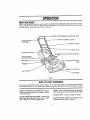
KNOW YOURMOWER
READ THiS OWNER'S MANUAL AND SAFETYRULESBEFOREOPERATING YOUR ROTARY MOWER.
Compare
the iJlustrallons with your
Rotary
Mower
to familiarize
yourself
with the location
of various
controls
and adjustments. Save this manual for future reference_
PRESENCE CONTROL
BAR
DRIVE CONTROL LEVER
-tANDLE KNOB
"CABLE
CLIP
STARTER ROPE
ENGINE SPEED
SELECTOR LEVER
_
OIL CAP WITH DIPSTICK
MUFFLER
_-----_
GASO LIN E FILLER
PRIMER
AIR FILTER
FIG, 4
Lul_ll
_ •
t
I I,llll'lU,
' IIIIII
i
Hill
II II
I'
II1'111_1
................................
MEETS
CPSCSAFETY
REQUIREMENTS
Sears Rotary Walk-Behind
Power Mowers
conform to the safety
dards institute and the UoSo Consumer Product Safety Commission,
iiii lUllll,i
iii,
ii1,11
iiii ,11
OPERATOR PRESENCE CONTROL BAR - must be
held down to the handle to start lee engine. Release
to stop the engine.
ENGINE SPEEDSELECTORLEVER.located onthe
r!_ht side of the engine whichallowsyou to select
effher "HIGH _ or "LOW" engine speed,
i _,,,_1
standards
of the American
National StanThe blade turns when the engine is running.
,,i,ii, lUiiiiiiiirlll
PRIMER- pumpsadditionalfuel fromthe carburetor
to the cylinder far usewhere startinga cold engine.
STARTER ROPE - usedfor starting the englne.
DELVECONTROL LEVERousedto engage powerpropelled forward motion of mower,
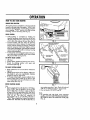
OPERATION
HOW TO USEYOURMOWER
ENGINESPEEDSELECTOR
The engine speed is controlled by a lever (red knob)
located on the right side of the en_line. HIGH" posi_
tion is For starting engine, normal cutting and better
grass bagging° "LOW" position is for light cutting,
trimming, and fuel economy (See Fig, 5)o
DRIVECONTROL
"
•
•
Self-propelling
is controlled by holding the
operator presence control bar down to the handle and pushing the drive control lever forward
until it clicks; then release the lever (See Fig. 6),
Forward motion will stop when the operator
presence control bar is released° To stop forward
motion without stopping the engine, release the
operator presence control bar slightly until the
drive control disengages° Hold operator presence
control bar down tohandle to continue mowing
without self-propelling.
To keep drive control engaged when turningcorhers, push down on handle and llft front wheels
off ground while turning mower.
FIG. 5
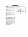
TO EMPTYGRASSCATCHER
• Lift Door.
• Grasp catcher handle and remove From mower,
o Empty by shaking catcher with open end
downward (See Fig. 7).
FIG. 6
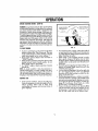
TOADJUSTCUFFING
HEIGHT
*
Raise wheels For low cut and lower wheels for
high cuL
o Wheels are set in low cut for shipping. Adjust cutting height to suit your requirements, Medium
position is best for most lawns.
* To change cutting height, squeeze adjuster lever
toward wheel Move wheel up or down to suit
your requirements. Be sure all wheets are in the
same setting (See Fig. B).
BEFORE
STARTING
ENGINE
OIL:
• Remove englne oil cap with dipstick or all fill plug.
Fill to "FUI_L" line on dipstick or to top o_slot
down in filbr hote_ Use about 1 pint or 1/2 liter
of Sears 30W all or equivalent. SAE 10W 30 oil
can also be used (See Fig, 4)° DO NOT use SAE
10W 40 oil. The total oil capacity
of _
your engine is 21 oz. or 0,62 liters. Fill only to
"FULL" llne on dipstick or to lop of slot down in
oil filler hole. DO NOT over filtoThe first fil! on a
,i,, ,11,11,1
IILI I,
FIG. 7
newengineusesabout I pint,Checkoil level and
add oil as needed to bring to proper level,
Pour oi! slowly, DO NOT over fill,
GAS:
• Fill gasoline tank with Fresh, clean unleaded
gasoline. DO NOT USE PREMIUM GASOLINE.
BE CAREFUL NOT TO OVER FILL TANK (SEE
F G.
4).
........................................
ii iiiii
ii
i_1
OPERATION
i
ii
I
,,111,1,1111111
I
i,,
iiii
,,,
,11,
i,ii1,1 I
BEFORESTARTINGENGINE (COt,IT'D)
WARNING: Experience indicates that alcohol blended fuels (called gasohol or usingethanol or methanol)
can attract moisture which leads to separation and
formation of acids during storage._ Acidic gas can
damage the fuel systemof an engine while in storage
To avoid _ngine problems, the ruet systemshouldbe
emptied before storage for 30 clays or longer. Drain
the gas tank, start the engine and let _trun until the
fuel )ines and carburetor ore empty. Use fresh fuel
next season. See Storage instructionsfor additlonal
_nformatlon. Never use engine or carburetor cleaner
products in the fuel tank or permanent damage may
occur,,
TO STARTENGINE
,
To start a cold engine, push primer five (5) times
before trying to start. Use a firm push. This step
is not usually necessary when starting an engine
which has already run for a few minutes_
* Push engine speed selector lever forward to
"HIGH" position,
handle and pun starter handle quickly° Do not
old operator
presence
control
bar down to the
allow
starter rope
to snap
back_
To "STOP" engine, release operator presence
control bar.
NOTE: In cooler weather it may be necessary to
repeat priming steps. In warmer weather aver prim_ng may cause flooding and engine will not start, if
you do flood engine wait a Few minutes before attempting to start and DO NOT repeat priming steps.
LOWER WHEELS
FOR HIGHCUT
RAISE WHEELS
FOR LOW CUT
FIG. 8
•
•
i
•
•
•
MOWINGTiPS
Under certain conditions, such as very tal_ grass,
it may be necessary to raise the height of cut to
reduce pushing effort and to keep from
overloading the engine and leaving clumps of
grass clippings,
_"'_
•
For extremely heavy cutting, reduce the width of
cut and raise the roar of the mower housing one
(1) wheel adjustor settinghigher than the front for
bettor discharge of grass_
When using a rear bagging mower in moist,
heavy grass, dumps of cut grass may not enter
the grass catcher. Reduce ground speed (pushing
speed) and/or run the mower over the area a second time,
For better grass bagging and mast cutting con.,
difions, the engine speed should'be set in the
"HIGH" (fast) position,
If a trail of grass clippings is left on the right side
of a rear bagging mower, mow _n a dockwlse
direction with a small overlap to collect the cllppings on the next pass°
For side discharge mowers, cutting in o counterclockwise direction, starting at the outside of the
area to be cut, spreads grass clippings more even*
ly and puts less load on the engine To keep clip..
pings off of walkways, flower beds, etc., make
the first cuts in a clockwise dlrecfiom
Pores in cloth gross catchers can become filled
with dirt and dust with use and co,hers will col!.
loci tessgrass. To prevent this, regularly hose catcher off with water and let dry before using,
GENERAL
RECOMMENDATION
Once a year you should replace the spark plug,
air filter, and check blade for wear, A new spark
plug and air filter assures proper air-fuel mixture
andhelps your engine run better and last longer,
You should check alt fasterners and be sure they
are tight°
Fottow the Service Recommendation Schedub on
page "[6..
gLADE/BLADE
FLANGECARE
Your mower will work better with a sharp bJade,
I
NOTE:We do not recommend sharpening blade, but
if you do, be sure the blade is balanced,
FROMSPARK
PLUGANDPLACE
WIREWHERE
IT
CANNOTCOME
IN CONTACT
WITH THEIII
CAUTION:DISCONNECT
SPARKPLUGWINE
......... SPARK,
PLUG.
I
TO SHARPEN BLADE:
° The blade can be sharpened with a file or on a
grinding wheel, Do not attempt to sharpen while
on the mower°
° Care should be taken to keep the blade balanced_ An unbalanced blade will cause excessive
vibration when running and eventual damage to
mower or engine.
" To check blade balance, drive a nail into a beam
or wall Leave about one inchof the straight hall
exposed° Place center hole of blade aver the head
of the nai!. IFblade isbalanced, it should remain
in a horizontal position, Ifeither end of the blade
moves downward, blade is not balanced,
Sharpen the heavy end until the Made is
balanced.
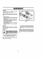
TO REMOVE BLADE:
• Turn mower' on its side. Make sure air filter and
carburetor are upo
', Use block of wood between blade and mower
housing to prevent blade from turning when nut
isremoved. Protect your hands with gloves and/or
wrap blade with heavy ctoth_
o Remove nut by turning counter-clockwise, Use a
15/16" box or open-end wrench,
NOTE: Check tab in blade flange after removing. If
tab is damaged, replace it. It mus! be in good condition for the blade to work properly° We recommend that a new blade nut be used each time blade
is removed.
TO REPLACE BLADE:
* Put blade flange on engine crankshaft with tab
in slot (See Fig 9),
o Fit blade on crankshaft in the blade flange. Be
sure the word "TOP (stamped on blade) is toward
engine,
° Place flat washer, two (2) formed washers and
nut on crankshaft (See Fig, 9).
o Use block of wood to holdblade and tighten nut
clockwise, The recommended torque is 70-75 ft.lbs. Torque wrenches are avalable at most Sears
stores and through the catalog°
t_lJk
ANDE_Y MAKETHEENGINE
HARDTOSTART
AUTION:A lOOSEBLA'O'E'_N
'BEDANGEROUS
i
Use only a Searsauthorized replacementblade to
get the best cutting resufts_
10
LJL
I
I
II
I '
I
I I
I
MAINTENANCE
,IIH,
I................................................
ii1,111 iii
i,iiii
IHI
iiii
i,,11,11
DELVEWHEELS
......................
1,1,1111,11
NOTE: Check front drive wheels each time before you
mow to be sure lhey move freely,
The wheels not turning freely means trash, grass, cut.
tings, etc_ are in the drive wheel area and must be
cleaned to free drive wheels_
If necessary to clean the dr_ve wheels, check both
front wheels,
* Remove hub caps, hairpin cotters and washers.
• Remove wheels From wheel adiusters.
o Remove any trash or grass cuttings from inside
the dust cover, pinion andlor drive wheel gear
teeth.
Put wheels back in place.
If after cleaning, the drive wheels do not turn free_y, contact your nearest Sears Service Center
,n
FJG. 10
ENGINE
TO CHANGEOIL
I_
FROMSPAREPLUGAND PLACEWIRE WHERE
IT
CANNOTCOME
IH CONTACT
SPARK
CAUrmN:
OtSCONNECT
SPA_ WITH
PLUG
WIRE
PLUG.
*
Remove engine oi} cop with dipstick; lay aside on
a clean surface Warm oil drains better_
o Tip mower on its side as shown in Fig 10 and
drain off into suitab|e container. Rack mower back
and forth to remove any all trapped inside of
engine.
* W_pe off any spilled oil on mower and on s?de
of engine.
i
the dipstick° DO NOT over fill.
ill engineengine
with oil,
only to the "FULL" line on
Replace
oil fi}l
cap.
Reconnect spark plug wire to spark plug
I!
ii
I
I
III
,
..................................
ii
...........................
MAINTENANCE
AIR FILTER
Your engine will not run properly and may be
damaged by using a dirty air filter.
Replace the air filler every year, more often if you
mow in very dusty, dirty conditions. Do not wash air
filter_
=
To Change Air Filler:
,, Remove the air filter cover by turning counler.,
clockwise to the stop and putl away from collar
(See Fig. 1 I).
•
•
•
Remove
filler
fromofinside
of cover
Clean
the
inside
the cover
and(See
the Fig.
collar11),
to
remove any dirt accumulatlon_
Insert new filler into cover_
Put air filter cover and filter into collar aligning
lhe tab with the slot.
Pushin on cover and turn clockwise to tighten (See
Fig. 11).
FIG. 11
• Cleanyour mower and engineoftentokeep buldup of trashfrom accumulatingaroundengine.A
clogged engine runshotter and shortensengine
life_
SPARKPLUG
Change your spark plug each year to make your
engine start easier and run better, Set spark plug
gap at 030 inch.
CLEANING
cAuTioN:
DlSCONMECr
SPARK
PLUG
wIRE
i
,_
FROMSPARKPLUGANDPLACEWIREWHEREI
tT CANNOTCOMEIN CONTACT
WITH SPARK|
PLUG.
I
•
•
Turn mower on its slde with carburetor up.
Clean the underside of your mower by scraping
to remove bufld_up of grass and trash.
NOTE:We recommendthatyou clean theunderside
of your mower after each use.
12
NOTE: We DO NOT recommend usinga garden hose
to clean mower unlessthe electrical system, muffler,
air filler and carburetor are covered to keep water
out. Water in engine can result in shortening engine
life.
............. SERVICE
AND ADJUSTMENTS
,
i
, ,
I i,
i i ii ,11111,...........................
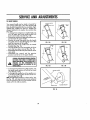
TO REMOVE/REPLACEDRIVE BELT
FROMSPARE
PLUG.,PLACE
WIREWHERE
IT CANCAUTION:DISCONNECTSPARI( PLUG WIRE I
NOT COMEIN CONTACT
WITHSPARKPLUG_
J .....
_lb
i
i
°
down
gear cover,
case pulley
(Seebelt
Fig.by12),
Removeon drive
Remove
pushing
Turn mower on its side with carburetor and fuel
cap up
Loosen hex head screw and move bell snubber
away from pulley (See Fig- 12)o
r .,,.,.k
PRESS--"r
carefully slip belt off over btade,
Caution: Sharp edges of blade can cut bell
i Install
emovenew
belt belt
fromreversing
engine pulley
on crankshaft
and
above
steps.
Move belt snubber back in place and tighten hex
head screw,
NOTE: Belt snubber clears belt by apprex_ 1132 inch
when installed.
• Always use only factory approved belt to assure
fit and long life,
_,_
ii1,1,1,
FIG. 12
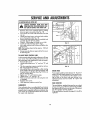
TO ADJUSTDRIVE CONTROLCABLE
]
,_3_
SCREW
:'A' "%, IC_'_I
AOJUS
G.
RO
e_TE
A drive control cable that needs adjustment wlll keep
your mower from self-propelling properly and can
also cause gear case componentsto wear out sooner.
- Remove drive cover_
• Loosen cable clamp screw'A" and nuts "B" and
IICfl
_
FiG. 13
i
•
•
dle and engage drive control,
Move shifter arm to drive position while rotating
front wheels to be sure jaw clutch is engaged° Pull
threaded sleeve with pliers (See Fig, 13). Do not
pull on control cable,
ie downnut
operator
presence
Tighten
"C" until
sleeve control
iS snug.bar to hanTighten screw "A" and nut "B",
Pushmower back and forth to be sure gear case
is engaged°
Replace drive cover.
Untie operator presence cantrot bar
ENGINESPEED
Your engine speed has been factory set, Do not attempt to increase engine speed or it may resultin personal injury. If youbelieve that the engine is running too fast or too slow, lake your mower to an
authorized Sears Service Center for repair and
adjustmenL
REARDEFLECTOR
CARBURETOR
The rear deflector, attached between the rear wheels
of your mower, is provided to minimize the possibilty
that objects will bethrown out the rear of the mower
into the operator mowing position,
If the rear deflector becomes damaged, it should be
replaced,
Your carburetor has a non-adjustable fixed main jet
for mixture control, If your engine does not operate
properly due to suspectedcarburetor problems, take
your mower to on authorized Sears Service Center
for repair and ad)ustment.
13
Your mower handle can be raised or lowered for
your mowing comfort. (Fig. 14A, 14B, 15A and 15B)
show the Four (4) positions that are ovalJable: High,
medium high, medium low and Iow. Handles are
shipped mounted in the medium low position (See
Fig. 14A)
• Ta change from medwumlow to medium high pasb
tion, the upper and lower handle sections will
have to be turned over (See Fig.. 14B).
• Remove the controls and operator presence control bar from the upper ha ndie.L
• Remove the starter rope guide from the handle
trim plate and two (2}self-tapping screws that
hold the trim plate to the handie_
• Disconnect the lower handle from the handle
brackets (See Fig. 16)_
• Turn the handle over and reassemble all of the
parts that have been removed (See Fig, 16)_
• Reassemble the handle trim plate and the starter
rope guide.
• Reassemble the controls and the operator
presence control bar to the upper handle°
FIG,14A
FIG.I4B
FIG. 1SA
FIG. tSB
CAUTION.,
THEOPERATOR
PRESENCE
CONTROL
BARMUSTPIVOTFREELY
TO PERMffBLADE
BRAKE
ENGAGEMENT
WHENCONTROL
BARIS
,
RELEASED.
DO NOT
OVERTIGHTEN
THE
FASTENERS
HOLDING
THE
CONTROLS
TOTHE
UPPER
HANDLE.
r
•
To change from medium low to high position, only
the upper handle section will have to be lurned
over (See Fig_ 15A)_
= To change from medium tow to low position, only the lower handle section will have to be turn_
ed over (See Fig. 15B),
NOTE:Handle height positions, as shown in fig, 14A
thru fig, 15B, are approximate and are measured
from t_e ground to the top of the handle with the
wheels set in the mid-cut position.
FIG.16
14
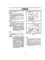
........................ STORAGE
Your mower and engine should be prepared for offseason storage as follows:
MOWER
•
,
•
•
.......
,11111111
Clean underside of mower housing. (See "Cleaning" in maintenance section of manuaL)
Inspect and replace/sharpen blade, if required
(See "Blade/Blade Flange Core" in maintenance
section of manual)_
Flose grass catcher off with water and let dry
before storing,
Lubricate as shown in Service Recommendation
chart on page 16 of manual.
0S7
/
r,.//
)2</]
HANDLE
•
You can Fold your mower handIe for storage as
shown in Fig° t7o
• To fold, squeeze the bottom ends of the lower
handle toward each other until Ihe lower handle
clears the handle bracket, then move handle forward (See Fig. 18).
IMPORTANT:WHEN FOLDING THE HANDLE FOR
STORAGE OR TRANSPORTATION,
BE SURE TO FOLD THE HANDLE AS
SHOWN IN FIG, t70 IF YOU FOLD
THE UPPER HANDLE SECTION THE
WRONG WAY, YOU MAY DAMAGE
THE CONTROL CABLES_
FIG. 17
ILOWER
HANDLE
ENGINE
ING
* Changeoil (See "To ChangeOil" inmaintenance
sectionof manual)
o Drain Fueland Run Engine until fuel systemis
empty°
IMPORTANT:IT IS IMPORTANT TO PREVENT
GUM DEPOSITS FROM FORMING
IN ESSENTIALFUELSYSTEMPARTS
SUCH AS THE CARBURETOR,FUEL
FILTER,FUELHOSEt ORTANK DUR.
ING STORAGE.ALSO, EXPERIENCE
INDICATES
THAT
ALCOHOL
BLENDED
FUELS
(CALLED
GASOHOL OR USING ETHANOL
OR METHANOL) CAN ATTRACT
MOISTURE WHICH LEADS TO
SEPARATION AND FORMATION
OF ACIDS DURING STORAGE.
ACIDIC GAS CAN DAMAGE THE
FUEL SYSTEM OF AN ENGINE
WHILE IN STORAGE.
PIN
FIGo18
OTHER
e
o
Do notstore gasoline from one seasonto another
Replace your gasoline can if your can startsto
rust° Rustandlor dirt in your gasoline can cause
_Droblems.
o nat storeyour mower under any plaslic cover.
Plasticcannot breathewhich allows condensallon
to form and can cause your mower to rusL
When settingup your handle from the storage
position, thelower handle wilt automaticallylock
rote the mowing position.
I1' '1
_ .dL,,i,--I
..........
III I!"li',h'_,_,l"l"'"lHl'
:':_
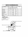
SERVICE
RECOMMENDATIONS
i
iii,
!11 i1,111_1,1iiii ,,,,,
i
, i:.................
;,;,,
--
iiii ,rl
SCHEDULE
SERVICE
RECORD
Fill in dalei
al you complete
service
First
2
Hours
Every
10
Hour_
Every
25
Hour_
Every
50
Hours
Every
Use
t/'
Blade_
sSharpened
Blades Replaced
v"
Engine Oil Change
v"
Engine
SERVICE
DAIE_
regular
O_1 Check
Air Cleaner
Replaced
Spark Plug Repfaced
Lubrlcale
Mower
Cfeoning
m
Grass Calcher (if applicable)
Muffler
Belt & Pulley
_'
- CHECK
BRICATIONCHART
SAE 30W
(lOW 30)
SPRAY
MOTOR
OIL
LUBRICANT
BRAKE SPRING BRACKET
(_
HANDLE BRACKET MOUNTING
_ENGINE OIL
WHEEL ADJUSTER
_"_
REAR DOOR HINGE
16
i ,
i_,
ii
,
LJl _
,l±_l,
1,1,, , iii, .......................
,
.................
,,,_
__1
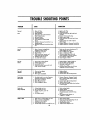
TROUBLE
SHOOTING
POINTS
iii
i,
i
II
ii,
i,,
i
PROBLEM
Doesnaf
Start
Pewer
Poort_Uneven
I
I
I
,,
iiiiiiiiiiii
i,ii
i,i
iiiiii,
i1,1,
71,
CORRECTION
CAUSE
..,
3.
4
I.
Replace Air Filter
Fil| gasoline tank,
3, Droln gas tank and refiff wile flesh
gasoline,
_ Cannoct wire la spark piugo
Dirt),oF
Air
Filter.
Ou)
gasoline
Stale Gaioltne.
Spark plug wire is disconnected
from tEe spark plug
_.• Water
Bad spark
plug.
in gasolineo
7o Looseblade or broken b_ade
flange,
8, Operator PresenceControl Bar in re'eased position
9. Operator PresenceControl Bar defec_
five
, Replace
spark plug.
Drain tankand
refll| with fresh, dean
gasoline
7- Tighten blade nut and/or replace
blade flange-
1,, Rear of mower housing/biotin
dragging in heavy grass.
Cuttingtoo much grass,
" Dirty air fi|ter
41 Build-upof gross, leaves, and
trash under mower houstng
5. Walhieg speed Ioo fast.
6., Too much ol_In engine,
I. Raise rear of mower housing one (t)
setting higher lean front,
2. Set in "Higher Cut" position.
3, C|ean or replace air fi{lar.
4, Oiscanned spark plug wire and
clean underside of mower housing,
5, Cut at slower walking speed,
6_ Check engine eli level,
),
2_
3.
4_
8, DepressOperator PresenceControl Bar
• Replace Operator PresenceCentre] Bar
Worn, bent or loose blade.
Wheet heightsuneven°
Low engine speed.
Build-upof gross, leaves and )rose
under mower hausingr
1., Set
Replace
blade atTighten
blade nut,
eli wheels
same height,
3. Sel engine speed selector
on
"HIGH" or "FAST"
4_ Disconnectspark plug wire & clean
undersideof mower housing
iiiiiiii iiiin iiiii
Toomuch
V]bratlon
1, Warn or bent blade.
LOOSe
b_adn
3, Benl engine crankshaft,
,L
SlerterRope
Held to PeI!
CatcherNot
Filling Completely
HARDTO PUSH
. Replace blade.
, "rigElenblade nut,
3, Contact Sears Service Department,
2r
L L i , L
J
t
, ,L ,
I
Flywheel brake is on when Operalor
PresenceControl Bar is released_
2_ Bentengine crankshaft,
3, Blade flange sheared
4. Blade dragging tn grass.
H
1, DepressOperator PresenceContra_
Bar to upper handle before pulling
on slorter rope.
2, Contact Sears Service Department
3_ Replace blade flange,
4.,Get over low grass ondlor hard surface
to start engine.
I° Raise culling helghL
I
Cu)ling
height',,yarn
too low.
Lift on blade
off,
3. Catcher bag dtrly, poor air
venting,
4_ Low engine speed,
.., Replace
blade catcher bag,
Clean/replace
if optional grass catcher is being
used •
4. Set engine speed selector on
"HIGH" or "FAST"
1. High Grass or culflng height too low,
2o Rear of mower houstngtblade
dragging in heavy grass,
3, Grass catcher too Full
4, Handle height position not right for you.
17
1. Raise cuffingheight,
2, Raise rear of mower housing one (1)
setting higher than front,
., Adjust
Empty grass
handlecatcher
height to suit-
i
REPAIR
CRAFTSMAN
22"
ROTARY
\
LAWN MOWER
917.372270
PARTS
REPAIR
CRAFTSMAN
Ref.
No.
PART
No.
,,J
22"
ROTARY LAWN
MOWER 917.372270
Part Name
Ref.
No.
i J
1
2
3
4
5
750081
700054
86874
84089
6
7
8
9
85827
700148
63688
34372A
85768
10
1!
12
13
14
63601
58714
51793
85424
85436
15
16
17
18
19
20
21
22
23
24
25
26
85529
85825
87594
88669
54583
88308
81283
88644
87596
41945
69180
87760
27
28
29
30
87145
51959
87569
87626
31
32
33
34
88653
88667
86914
86915
PARTS
Part
No.
Part
Name
HHI
Upper Handle
Lower Handle
Zone Control
Bail Control
Hex Thread Rolling Screw 10-24
x 3t4
Cable Clip
Handle Pad
Handle Knob
Bracket rope Guide (See Engine
Parts List) (Source !43|
Locknut 1/4-20
Handle Bolt 5t16-18 x ! 314
Hairpin Cotter
Trim Plate
Hex Washer Head Machine Screw
114-20 x t 1/2
Nylon Bushing
Tapping Screw 10-24 x 1
Side Baffle
Discharge Baffle
Self Tapping Screw 1/4-20 x 112
Pop Rivet 1/8 x 318
Self Tapping Screw 10-24 x 3/8
Back Plate
Rear Baffle
Threaded Screw 10_24 x I/2
Lacknut 10-24
Rear Door (Use 48137 Doer &
Hinge Kit)
Spr_ng
E-Ring
Hinge Rod
Hinge Bracket {Use 48137 Door &
Htnge Kit}
Sealing Strip
Rear Skirt
Handle Bracket Assembly (Left)
Handle Bracket Assembly (Right)
35
55187
36
37
38
39
4O
41
42
43
44
45
46
47
48
49
50
51
52
53
54
55
56
57
63124
_JOffT6
7EOO-T5
84920
86929
77865
87887
62335
84921
87727
52160
55015
77400
66238
74400
87587
69334
51433
54867
69385
87712
48108
58
59
60
61
62
63
64
85463
68205
83629
87677
85543
85446
83813
65
56
70385
81276
67
68
69
7O
87272
85425
88652
750036
750039
Thread Cutting Screw 5116-18 x
314
Locknut 5/16-18
Wheel Adjusting Bracket (Left) _Tt
Wheel Adjusting Bracket (Right) _;
Spacer •
Selector Spring
Selector Knob
Axle Arm Assembly
Spring Washer
Shoulder Bolt
Wheel & Tire Assembly 9 x 2
Washer
Retainer Cllp
Hubcap
Carriage Bolt 5t16-18 x 518
Locknot 318-16
Front Baffle
Blade 22"
Locknut
BellviUe Washer
Washer
Blade Flange
Mower Housing gnc. Ref_ 17. 22.
25 & 511
Danger Decal
Hex Head Screw 5/16-18 x 7!8
Belt Snubber
Hi Pro Key #HP-5O5
Engine Pulley
Cable Assembly
Hex Head Machine Screw 10-32
x 9132
Cable Clip
Hex Head Tapping Screw 10-24 x
t12
Instruction Decal
Trim Plate Decal
Hinge Screw
Engine Assembly 143.394232
(See Pages 22-241
Owners Manuat
REPAIR
CRAFTSMAN
22"
ROTARY
PARTS
LAWN MOWER 917.372270
23
39
22
1,o
O
_0
REPAIR
CRAFTSMAN
Ref.
No.
1
2
4
5
6
7
to
22"
ROTARY
LAWN MOWER
917.372270
Part
No.
Part Name
Ref.
No.
Pert
NO,
87025
48029
48030
750029
74189
83691
61528
Drive Control
Drive Heed Kit
Drive Control Cable Kit
Machine Screw 10-24 x 2
Locknut 10-24
V-Belt
Flat Head Machine Screw 114-20 x
314
Hex Head Bait 114-20 x 314
RetainTng Ring
Wheel Adjusting Bracket _J_
"i_'OG_"
27
28
29
30
31
32
33
34
35
36
37
63601
68038
Axle Arm Assembly
Knob
38
!750097
39
40
41
42
43
44
45
46
47
48
49
50
51
!87885
:4_095
148096
169180
87682
87679
:87873
87678
:700216
87871
87870
103227X
8
9
10
11
12
13
14
15
16
17
18
19
20
21
22
23
24
25
54338
STD582087
_694_
88285
77865
86937
86939
86274
86273
764O1
74507
STD581050
87729
86960
52160
55015
77400
750108
26
83700
_
Selector Spring (Left)
Selector Sp#ng (Right)
Spring Washer
Spacer Bearing
Dust Cover
Pinion
E-Ring
Wheel & Tire Assembly 8 x 2
Bushing
Washer
Retainer Clip
Hubcap
Hex Washer Head Tapping Screw
10-24 x 3/8
Cable Clamp
PARTS
_-00|(o
i75192
157076
i55692
i48128
i83681
!74976
187691
187866
Pe_
Name
Locknut 1/4.20
Locknut 1/4,20
Spring .,- _L_.'_,,
Spring
Woodruff Kay #213
Woodruff Key #3
Gear Case Replacement Kit
Drive Pulley
Retaining Ring
Drive Cover
Pan Head Tapping Screw 10-24 x 2
3/4
Hex Head Tapping Screw 10-24 x
1/2
Drive Cover Decal
iWheel Adjuster Assembly (Left)
Wheel Adjuster Assembly (Right)
Locknut 10-24
Catcher Baffle
Catcher Bottom
Truss Head Screw 10-24 x 5/8
Catcher Top
Setf Tapping Screw 10-24 x 5/8
Catcher Frame
Truss Head Screw 114,20 x 518
Catcher Handle
Clipping Deflector Accessory (not
nctuded with mowerJ 71 33303
CRAFTSMAN
22" POWER.,PROPELLED
LAWNMOWER917.372270
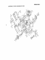
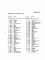
REPAIRPARTS
GEARCASEASSEMBLY
PARTNUMBER88448
B
Pa_
No,
Parl Name
ReL
Ha.
Parl
No.
Part Name
!
2
3
4
5
6
53838
85178
88386
57072
57388
48032
gaps LocknutI/4-20
Adusltng Era&at
Shifter Assemby
f_al
GroovedPin I/8 X I/2
77881
77039
79946
57879
75144
87822
86447
83659
75424
63304
_D58|050
83684
83720
65692
83680
5TD5225t2
GroovedPin I/8 x 3/4
Plug
Helical Gear
7
8
9
10
!1
12
13
14
15
16
17
I8
19
20
21
22
Ref.
No.
Gear CaseHalves(Inc. Upper &
LowerHalves) (Ind. Role 4, S, 7)
Bearing
SpringBracket
Drive Shah Gear
Hardened Washer
Yoke Clutch
22
JewQuoth
Grease
E-RIn8
_uare Key
Warm Shaft
Woodruff Kay//3
Worm
HoxHead'raw!/4-20 x
! I/4
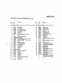
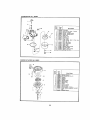
CARBURETOR
NO. 632388
ReL
No,
Vntt
I
Part
Name
f
1
3
4
5
6
7
9
11
12
15
!3
14
15
16
21
22
25
_t6
L
12
I
I
26
_------2t
632388
63t615
631616
65_5_6
631767
E'_t971
53t11_
532047
631027
531021
_1022
332019
_1024
_31700
_31334
_31935
k3102FJ
k"Z177R
] Carburolor
! Shaft _- Lever Asey _ ThrotUe
t Shutter, Throttte
I Screw. Throttle shutter
! Spdng, Throttle return
1 Seat, Dust
I Washer, Flat
I PHrner Assy
I Plug, Welch
!inle_ Needle, Seat 6 Cllp Assy
llnct No. 13)
I Clip, inlet needle
t Float, Carburetor
t Shaft, Float
ISowf, Fioat
I Gasket, Bowl-to-body
I Nut, Float bowl
I Gasket, Bowl..to-body
I Fitting, Fuat iniet
i
i
J
t
REWIND
STARTER
NO,
/
590621
u ==
H=H, H
Rel
No,
28
Part
No.
1
2
3
4
5
6
7
8
9
10
1I
12
590621
590599,
59O6O0
590615
590601
59_598
590816
590617
.%_0618
590619
590620
59O622
690535
13
590452
Part Name
Starter, Rewind
Pin, Spdng {Incl. No 4)
Washer
Retainer
Washer
Spring, Brake
Dog, Statler
Spring, Dog
Pulley
Spring, R_wind
Cover, Spring
Ho_Jslng Aeey. Starter
Rope, Starter (Length 98 °` 8" g164'"
dieJ
Handle, Sterter
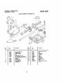
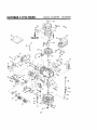
CRAFTSMAN
4"CYCLE
ENGINE
MODELNUMBER:143.394232
24
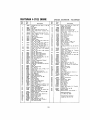
CRAFTSMAN
4-CYCLE
ENGINE
Part
No,
34959
26727
32600
293t48
29315C
29313C
29315C
31672
31673
35175
32323
35544
35545
35546
35541
35542
36543
35,547
35548
35549
20381
309638
32510A
27241
33148A
29914
"35261
34311S
27897
°28833
30572
650488
35479
30574
30591
29193
30588A
31335
30589
28277
31383A
31361
611004
"32643A
34335
6021A
35395
"27234A
32755
30200
34215
"32760A
650128
34985
35168
'34690A
31384A
650451
34337
Part
MODFLNUMBER:
Ref
No.
Name
Cylinder Assy linct Nos 3, 4 54, 55
e 56)
Pin. Daws!
Seal. OIl
Valve. Intake (Std.l (Inot No 101
Valve. intake 1t/32" oversize) (_nc(
No I0)
Valve, Exhauet (Std I (IneI No 101
Valve,
Exhaust
(t/32"
oversize)
(InC) No 10)
Spring, Ve)ve
Cap, Lower vatve spring
Crankshaft
Washer. Thrust
Piston. Pin B" Ring Assy (Std) ()nc_
Nes 14A, 15 E_ tfI
P(stono Pin 8 Ring Assy, (,010 oversize) ((ncL Nee, 14A, 15 Et 161
Piston, Pin _" Ring Assy, ( 020 over,
size] {)ncL Nee 14A, "!5 8- 16)
Piston 8" Pin Assy. (Std) (IncL No 161
Piston e Pin Assy
(O10 oversizeI
find
No, !61
Platen 8- Pin ASSV (020 oversize}
find
No 161
Ring Set. Piston (Std,I
Ring Set. Piston ( 010 overslzeI
Ring Set. Piston ( 020 ove_sizeI
Ring. Piston pin retaining
Rod Asey, Connecting (lnd No 18)
Bolt, Connecting rod
Lilter, Valve
Camshaft (Compression Release)
Pump Asay, Oil
GaskeL Mounting flange
Flange Assy , Mounting Und NOS 26
27, 28, 32)
Seat, eli
Gasket, Oil drain piu8
Plug,Oildra_n
Screw, He;{ hd Seine, 1/4-20 x 1.1/4
Washer. Flat
Shaft. Mechanical governor
Gear Assy, Governor find No 31}
Ring. Retaining
Spool Governor
Clamp, Governor lever
Rod, Governor {lnclNo 38)
WasheL Fiat
Lever, Governor
Spring, Governor
Key, Flywheel (Solid State)
Gasket, Cytindat head
Heed, Cylinder
Screw, Hax flange hd, 51t618x 1112
Resistor Spark Plug (Champion
RJ19LM or equivalent}
Gasket, VaNe spring cover
Cover, Valve spring box
Screw, Hex washer hd Seres, soil,,
tapping. 10_24 x 9/16
Breather Assy flncl Nee 54 _ 561
Gasket, Breather
Screw. Hex hd, Seres, 10-24 x 112
Retalner_ Starter rope
Bracket, Rope guide
Gasket, Intake
Pipe, Intake (incl. No 59)
Screw. Hex hd Some, 114-20 x 1
Unk, Governor spring
25
Part
No.
71
30200
72
73
74
75
78
338O2
31342
650777
650549
35727
77
78
79
80
81
82
83
85
86
87
88
89
32410
34336
35167
34961
35065
35067
"28756
6201
29752
35065
35068
3331
90
98
99
650548
35478
950831
t00
302O0
101
I02
tO3
105
105
107
108
120
121
123
36565
35355
26460
34357
650815
650816
35000
271816
650796
650562
124
t25
126
!26A
130
t3!
!33
t34
135
34265
35577
35578
35499
35392
650884
610118
34443A
650814
136
137
138
139
140
141
t42
t43
145
34080
611112
35015A
34965
34966
32309
34968
610973
550839
150
151
152
632388
580621
33238D
143.394232
Part Name
Screw, Hex washe_ hd Same sel(
topping. 10-24 x 9/16
Spdng Compression
Spring Compression
Screw, FH hd 532 x 21 32
Screw, Fil hd . 6,40 x 7 t6
Control Assy. Speed Hncl Nos 72
73, 74 8 751
Knob, Speed conlrO)
Link, Govemor,tc-thfoItle
_eeeL
Inst ructiO_
Wire. Ground
Cover Air cleaner
Col(at, Air cleaner
Gasket, Carbutelo_
Screw. Hex hd, I 4-28 x 7 8
Nut &' Lockwasher
1 4-28
Filter, Air cleanm
Clamp, Air cIeane_
Ai_ Cleaner Kit ((ncINoB 81 82 87 Er
881
Screw, Hex washer hd 8-32 x 5 16
Hot, sing Blower
Screw
Hex washer hd
Powedok
thread 1_4-20 x 15 32
Screw. Hex washer hd Same sol(
tapping,10-24x 9 16
Tank Aesy,. Fuel (loci No 102,9 1031
Cap. Fuel tank
Clamp, Fuelline
Line. Fuel
Washer, Beltoviile
Nut Flywheel
H_b, Starter
Muffler Assy (Ind No. 121I
Screw r Hex hd, 1 4,20 x 2 1 4
Screw, Hex washer hd shake-,proof
!0.32 × ] 2
Gasket. Oil fU) tube
Tube Assy. Oil filler
Dipstick,
O(I
"O" Ring
Plug, Starter
Screw. Hex washer hd
532 x I 2
Cover, Spark plug
SolidState Assy
Screw, Terx hex washer hd Some
10,24 x 1
Spacer, F)ywheel Key
Ftywhee!
Bracket Assy, Brake
Spdng, Extension
Link Control
Ring, Re_aining
Level Brake
Te_minat ASSy
Screw. Hex washer hd
PowerIok
1,'4-20 X 3 B
Carburetor (InelNo B3I
S tarter,
Rewind
Gasket Set (Incl
items marked "}
RPM Speed Settings:
Low. 2050; High, 3000
"indicates Parts included in
Gasket Set. Ref No 152
NOTES
26
NOTES
27
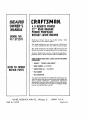
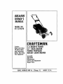
I:RRFTSMRNo
OWNER'S
MANUAL
4.0 RESERVE
POWER
22" REARBAGGER
POWERPROPELLED
ROTARYLAWNMOWER
MODELNO.
917.372270
Each Lawn Mower has its own model number° Each
engine has its own model number.
The modeI number for your lawn mower will be found
on a decal attached to the rear of the mower housing°
The model number for the engine wilS be found on the
Blower Housing of the engine adjacent to the spark pbgo
All parts listed herein may be ordered through Sears,
_ Roebuck and Co, Service Centers and most Retail Stores.
WHENORDERING
REPAIRPARTS,ALWAYS
GIVETHEFOLLOWING
INFORMATION:
* PRODUCT
- "ROTARY LAWNMOWER"
* MODELNUMBER- 917.372270
HOW TO ORDER
REPAIRPARTS
" ENGINEMODELNOr - 143.394232
* PARTNUMBER
* PARTDESCRIPTION
Your Sears merchandise has added value when you consider that Sears has service unitsnationwide staffed with
Sears trained technicians_.,,professionat technicians
specificallytrained on Sears products, having the parts,
tools and the equlpmenl to insurethat we meekour pledge
to you, we service what we sell.
SEARS,
750039
Rev, 1 02127/89
ROEBUCK
AND
CO.,
Chicago,
IL.
60684
U.S.A.
Printed In U_S.A,